a vhdl front end
TRANSCRIPT

A V H D L F R O N T E N D
By
Baokang Chen
B. Sc. (Computer Science) Zhejiang University, P.R. China , 1984
M . Sc. (Computer Science) Zhejiang University, P.R. China, 1987
A THESIS S U B M I T T E D IN PARTIAL F U L F I L L M E N T O F
T H E R E Q U I R E M E N T S F O R T H E D E G R E E O F
M A S T E R O F S C I E N C E
in
T H E F A C U L T Y O F G R A D U A T E STUDIES
C O M P U T E R S C I E N C E
We accept this thesis as conforming
to the required standard
T H E UNIVERSITY O F BRITISH C O L U M B I A
November 1994
© Baokang Chen, 1994
In presenting this thesis in partial fulfilment of the requirements for an advanced
degree at the University of British Columbia, I agree that the Library shall make it
freely available for reference and study. I further agree that permission for extensive
copying of this thesis for scholarly purposes may be granted by the head of my
department or by his or her representatives. It is understood that copying or
publication of this thesis for financial gain shall not be allowed without my written
permission.
Department
The University of British Columbia Vancouver, Canada
DE-6 (2/88)

Abstract
V H D L (the V H S I C Hardware Description Language) is an industry standard language
used to describe hardware from the rather abstract behaviors to the very concrete circuits.
This thesis is about the design and implementation of a V H D L front end. A brief
introduction to V H D L is given with easy-to-understand examples. Our focus of the
front end is on type checking and overload resolution in V H D L . Data structures and the
approach to parsing V H D L are discussed in detail. We also propose a program interface
to the front end and provide users with a set of library routines for further processing of
a V H D L program. The application of the front end is illustrated by the elaboration of
generate statements.
n

Table of Contents
Abstract ii
List of Tables vi
List of Figures vii
Acknowledgement ix
1 Introduction 1
1.1 Motivations and Objectives 1
1.2 Thesis Outline 2
2 Introduction to V H D L 3
2.1 History of V H D L 3
2.2 Structural Modeling 4
2.3 Behavioral Modeling 7
2.4 V H D L as a Programming Language 9
2.4.1 Type System 10
2.4.2 Overloading 13
2.4.3 Aggregates 15
3 Parsing V H D L - Lexical, Syntactic and Semantic Analysis 17
3.1 Lexical Analysis 17
i n

3.2 Syntactic Analysis 19
3.3 Semantic Analysis 20
3.3.1 Type Checking 21
3.3.2 Overload Resolution 22
3.4 Error Handling 25
3.4.1 Syntax Errors 26
3.4.2 Semantic Errors 26
4 Data Structures 28
4.1 Nodes 28
4.2 Parse Trees 28
4.3 Type Tree , • • • 30
4.4 Symbol Tables 32
4.4.1 General Symbol Table Structure 34
4.4.2 Construct-specific Data Structures 36
5 Program and Library Interfaces 38
5.1 Program Interface 38
5.1.1 Annotated Parse Tree 38
5.1.2 Tree Traversal Paradigm 40
5.2 Library Routines 42
5.2.1 Parse Tree Building 42
5.2.2 Parse Tree Traversal 43
5.2.3 List Processing 43
5.2.4 Accessors to Node Structure 43
iv

5.2.5 Accessors to Type Trees 44
5.2.6 Accessors to Symbol Tables 45
5.2.7 Miscellaneous 45
5.3 Applications 46
6 Restricted and Unsupported Constructs 50
6.1 Unsupported Constructs 50
6.2 Restricted Constructs 54
7 Conclusion and Future Work 60
7.1 Conclusions 60
7.2 Future Work 61
Bibliography 62
Appendices 64
A V H D L Grammar 64
B Data Structure Definitions 86
C Library Routine Specifications 93
C l Parse Tree Bui ld ing 93
C.2 List Processing 94
C.3 Accessors to Type Trees 95
C.4 Accessors to Symbol Tables 96
D V H D L Example 98
v

List of Tables
4.1 Descriptions of Fields in the Node Structure 30
5.2 Descriptions of Annotated Items 39
vi

L i s t of F i g u r e s
2.1 The circuit representation of a half adder 4
2.2 Implementation of the Half Adder 6
2.3 Structural Description of the Half Adder 7
2.4 Behavioral Description of a Nand2 Gate 10
2.5 Examples of Overloaded Subprograms and Enumeration Literals 14
3.6 Phases of the V H D L Front End 18
3.7 A n Example of the Parse Tree 20
3.8 Resolution Algorithm for Overloaded Enumeration Literals 23
3.9 Resolution Algorithm for Overloaded Subprograms . 24
4.10 Node Structure 29
4.11 General Tree Structure 30
4.12 General Type Tree Structure . 31
4.13 Type Tree for Integer and Enumeration Types 32
4.14 Type Tree for Physical Types 32
4.15 Type Tree for Record Types 33
4.16 Type Tree for Array Types 33
4.17 The Hierarchy of Symbol Tables 35
4.18 Data Structure for a Symbol Table Entry 36
5.19 The Style for Tree Traversal Routines 41
vii

5.20 Grammar of a G e n e r a t e Statement 46
5.21 Algorithm for G e n e r a t e Elaboration 48
5.22 Elaboration of a G e n e r a t e Statement 49
viii

Acknowledgement
First of all, I would like to thank my supervisor, Dr. Carl Seger, for his guidance,
commitment and support during my graduate studies at U B C .
Thanks to Dr. Mark Greenstreet for being the second reader of this thesis and his
invaluable comments.
Thanks to the Department of Computer Science for providing me with wonderful
working environment, research facilities, and financial support throughout my graduate
studies at the University of British Columbia.
Last but not least, I am indebted to my wife and my parents for their love, patience,
and encouragement.
ix

Chapter 1
Introduction
1.1 Motivations and Objectives
The VHS IC Hardware Description Language (VHDL ) [LRM87] is an industry standard
language used to describe hardware from the rather abstract behaviors to the very con
crete circuits. Since its emergence as an I E E E standard in 1987, V H D L has been widely
embraced as a popular communication medium of designs. Several companies and insti
tutions have developed or are developing tools based on V H D L . These include simulation
tools, verification tools, synthesis tools, layout tools[Greiner93], etc.
Given a V H D L program, the first stage of a VHDL-related tool is a module called the
analyzer. The analyzer performs the syntactic and semantic analysis of V H D L source
code and inserts intermediate form representations of design units into a design library
if no errors occur. From the point of view of compilation, the analyzer can also be called
the front end of the compiler.
Several V H D L compilers are available commercially or in the public domain. Unlike
other high-level language compilers, a V H D L compiler produces object code which cannot
be run independently. Compilation is a preprocessing step before further use. In addition,
the object code has no standard format since it is not defined in the I E E E standard. On
the other hand, some universities and institutions have already developed various C A D
tools which are not intended to support V H D L . They may need to adapt their tools to
1

Chapter 1. Introduction 2
the support of V H D L because of its popularity. This need motivates the development of
a V H D L front end.
There is a V H D L front end available in the public domain. It was developed at the
University of Twente in the Netherlands. However, that front end only supports a small
subset of the V H D L language. Laboratoire M A S I / C A O - V L S I at the University of Pierre
et Mar ie Curie in France also developed the All iance V L S I C A D system[Greiner93]. This
system supports an even smaller subset of the language.
The objective of this thesis was to develop a V H D L front end which supports a large
subset of V H D L . It was developed from scratch and is written i n C. The output of the
front end uses a generic tree structure which can easily be processed further. In addition
to the tree structure, a set of l ibrary routines are provided to get access to information
obtained during the syntactic and semantic analysis.
1.2 Thesis Outline
The rest of this thesis is organized as follows. Chapter 2 introduces V H D L fundamentals
from a user's prospective viewing V H D L as a model of structure, as a model of behav
ior, and as a programming language. Chapter 3 discusses techniques used for lexical,
syntactic and semantic analysis of V H D L programs. The data structures used i n the
implementation are presented i n Chapter 4. Chapter 5 describes the interface provided
to the users for further processing of V H D L programs. A n example application of the
front end is also given i n this chapter. Unsupported and restricted constructs of V H D L
are listed in Chapter 6. Examples are provided to illustrate those constructs. Chapter 7
concludes the thesis with suggestions for future work.
Chapter 2
Introduction to V H D L
V H D L (VHSIC Hardware Description Language) is rapidly emerging as one of the most
important electronic design languages in both the commercial and military electronic
design areas. This chapter will summarize the history of the language and present V H D L
fundamentals from a user's perspective viewing V H D L as a model of structure, as a model
of behavior, and as a programming language. Further detailed information on V H D L can
be found in [LRM87], [Ashenden90], [Coelho89], [Lipsett89], and [Perry93].
2.1 History of V H D L
The V H D L project was initiated by the US Department of Defense in the summer of 1981.
The objective was to advance the state of the art in the areas of design, process, and
manufacturing technology. In August 1985, Intermetrics released the V H D L 7.2 Language
Reference Manual, which has become the baseline language of the I E E E standard. In
1986, V H D L was proposed as an I E E E standard. It went through a number of revisions
and changes until it was adopted as the I E E E 1076 standard in December 1987.
Since its emergence as an I E E E standard, many companies have entered the V H D L
marketplace, and many are expanding their current offerings. Various tools and design
environments are available to the digital device designers. V H D L has established itself
as a significant hardware description language.
It is an official I E E E requirement that all standards be reaffirmed at least every 5
3

Chapter 2. Introduction to VHDL 4
years. Thus, the standard 1076-1987 was restandardized and the new standard 1076-1993
was approved by the I E E E in September 1993. Several changes, although not radical
changes, are reflected in the I E E E Std 1076-1993. Since the new Language Reference
Manual was not available when the work described in this thesis was performed, the
standard I E E E 1076-1987 is the language used in this thesis.
2.2 Structural Modeling
When a design engineer develops a new piece of hardware today, it is probably designed
on a computer-aided engineering (CAE ) workstation. To create a design on a typical
C A E workstation, the designer will create a schematic for the design.
A typical schematic consists of symbols representing the basic units of the design
connected together with signals. The symbols come from a library of parts that the
designer uses to build the schematic. The type of symbols available depends on the type
of design that the designer is creating. V H D L supports this kind of design and provides
constructs for it.
To illustrate the use of V H D L for describing structure, consider the design of primitive
circuit used in binary addition called a half adder or H A . A half adder adds together two
bits A and B to give a sum, S, and a carry, C, as shown in Figure 2.1.
Half Adder (HA)
Figure 2.1: The circuit representation of a half adder
The relationship between inputs and outputs can be described by the following

Chapter 2. Introduction to VHDL
Boolean equations:
5
S = A-B + A-B = A® B
C = A-B
In V H D L , this circuit is described as an entity. A n entity corresponds directly to a
symbol in the traditional C A E workstation design methodology. A n entity for the H A
would look like this:
e n t i t y halfAdder is
g e n e r i c (delay : Time := 1 0 ns) ;
p o r t (A, B : i n Bit ; S, C : o u t Bit) ;
e n d halfAdder;
G e n e r i c s provide a channel for static information to be communicated to a block
from its environment. Such information may be the delay of a component, operating
frequency, and the width of a data path, etc. P o r t s are external views of an entity and
consist of inputs and outputs. The e n t i t y defines the interface to the outside world. It
specifies the number of ports, the direction of the ports, the type of ports, and generic
information (if any) as well.
Figure 2.2 shows one implementation of the half adder. This implementation uses
three nand gates an an inverter. Interested readers can prove the logical equivalence
between the implementation and the Boolean equations given above.
The schematic for the half adder is described by an a r c h i t e c t u r e . A n architecture

Chapter 2. Introduction to VHDL 6
A
B
Figure 2.2: Implementation of the Half Adder
defines the body of a design entity. It specifies the relationship between the inputs
and outputs of a design entity, and may be expressed in terms of structure, dataflow,
or behavior (discussed later). A n architecture for the H A corresponding to the above
implementation is given in Figure 2.3.
In V H D L , each component used in the schematic is described by a component in
stantiation statement. Each statement creates an instance of a component in the model.
In this example, four instances of nand2 gates and one instance of an inverter gate are
created. For simplicity, each instance has the same name (called label in V H D L ) as
the one in the schematic. Within the architecture, interface ports can be used directly.
Intermediate signals for interconnection of instances are declared by signal declaration
statements. Correspondences between formal ports and actual ports can be established
in two ways: positional and named association. Positional associations specify actual
ports in the same order as in the interface list. Instances N G l , NG2, NG3 use this as
sociation. Named associations explicitly give formal port names and their corresponding

Chapter 2. Introduction to VHDL 7
architecture structure of halfAdder is
component nand2
port (A, B : in Bit ; Y : out Bit) ;
end component ;
component inverter
port (A : in Bit ; Y : out Bit) ;
end component ;
signal Y l , Y2, Y3 : Bit ;
begin
NG1 : nand2 port map (A, B, Y l ) ;
NG2 : nand2 port map (A, Y l , Y2) ;
NG3 : nand2 port map ( Y l , B, Y3) ;
NG4 : nand2 port map (A => Y2, B => Y3, Y => S) ;
IG1 : inverter port map (A => Y l , Y => C) ;
end structure;
Figure 2.3: Structural Description of the Half Adder
actual port names in the form of (formaLport => actuaLport). In this case, port
associations can be given in any order. Instances NG4 and IG l belong to this kind.
2.3 Behavioral Modeling
In many cases, it is not appropriate to describe a module structurally. One such case is
a module which is at the bottom of the hierarchy of some other structural description.
In the example of the H A above, the design is specified in terms of inverter and nand2
gates. Those gates may just use existing IC chips. In such cases, a description of the

Chapter 2. Introduction to VHDL 8
function performed by the module is required, without reference to its actual internal
structure. Such a description is called a functional or behavioral description.
In V H D L , the behavior of a digital system is described in terms of a programming
language notation. Many programming constructs and features for behavioral description
are similar to modern imperative languages. V H D L provides following constructs for
behavioral modeling:
• data type declarations,
• variable assignment statements,
• signal assignment statements,
• if statements,
• case statements,
• loop statements,
• subprograms (procedures and functions),
• process statements, etc.
As an example, the behavior of the half adder can be expressed as follows:
architecture behavior of half Adder is
begin
S <= A xor B after delay ;
C <= A and B after delay/3 ;
end behavior;

Chapter 2. Introduction to VHDL 9
Again, architecture is used for behavioral description. A n entity can have multiple
architectures describing different bodies of the entity (maybe different implementation of
an entity). In this example, two concurrent signal assignment statements are adopted.
What makes these statements different from assignment statements in typical program
ming languages is the fact that these statements execute in parallel (concurrently), not
serially.
The after clause in the signal assignment is used to emulate propagation delay in the
circuit. Different delay time can be expressed by an expression in the after clause. In
the above example, constant delay is declared in the entity declaration. The carry C
takes shorter delay than the sum S because a shorter path is taken from the input A and
B to the output C.
Figure 2.4 is another example of a behavioral description. It is a model of a two-input
nand gate.
In this example, different rise/fall time for a gate is emulated. Two steps are adopted
to simulate this nand gate. At the first step, the output temp is acquired without any
delay (the first variable assignment statement). A delay-variable buffer is then used.
Based on the different value of temp, the buffer gives different delay. Note that the
statements within a process are executed sequentially.
2.4 V H D L as a Programming Language
As a programming language, V H D L inherited many of the latest trends in the area of
imperative languages, especially through Ada[Barnes89]. Many programming constructs
and features are similar to those in other high-level programming languages. For example,
there are IF statements, CASE statements, LOOP statements, subprograms (functions

Chapter 2. Introduction to VHDL 10
entity nand2 is
port (A, B : in Bit ; Y : out Bit) ;
end nand2;
architecture behavior of nand2 is
begin
process (A, B)
variable temp : Bit ;
begin
temp := not (A and B) ;
If (temp = '1') then
Y <= temp after 4 ns ;
else
Y <= temp after 2 ns ;
end i f ;
end process ;
end behavior;
Figure 2.4: Behavioral Description of a Nand2 Gate
and procedures) in V H D L . However, V H D L has its own features because of its nature,
as a hardware description language. These features are reflected in both semantics and
syntax. The following subsections will highlight these features.
2.4.1 Type System
Like many other languages, V H D L provides data abstraction facilities which include
a full, user-definable, type model. There are four classes of types. Scalar types are

Chapter 2. Introduction to VHDL 11
integer types, floating point types, physical types, and types defined by an enumeration
of their values. Physical types allow measurable quantities, such as time, to be expressed.
Composite types are array types and record types; values of these types consist of element
values. Access types provide access to objects of a given type. They can be thought of
as pointers or references to objects. File types provide access to objects that contain a
sequence of values of a given type. A n object in V H D L is an entity that contains a value
of a given type. There are three kinds of objects: constants, signals, and variables.
To understand the type system, distinction need to be made between type definitions
and type declarations. A type definition defines the class of a type and domain of values
which an object of this type can take on. A type declaration associates a name with a
type definition. Thus the declared type can be referenced by name. In V H D L , the type
of an object must be specified by a type name. The following example illustrates this:
array (1 to 10) of Integer — type definition
type A is array (1 to 10) of Integer ; — type declaration
signal S i : A ; — signal declaration
signal S i : array (1 to 10) of Integer ; — illegal declaration
In V H D L , each object has two types: base type and subtype. The base type (un
derlying type) is defined by type declarations or implicitly. Domain theory[Hen88] is
helpful in explaining these types. A type declaration defines a domain of values that are
completely different from the values in the domain defined by any other type declaration,
even if two type definitions are textually identical. In some cases, it is known that an
object will take on values from only a subset of the values defined by its type. To capture
such a design restriction, V H D L provides the notion of a subtype. A subtype declaration

Chapter 2. Introduction to VHDL 12
defines a subset of the values of a type specifying a constraint on the type. In other
words, a subtype is a type with constraints. As an example, consider the following:
type A is range 1 to 10 ; — declare type A
type B is range 1 to 10 ; — declare type B
subtype C is A range 1 to 5 ; — subtype declaration
In this example, type A and B are distinct integer types even though they have same
domain of values and belong to the same type class. Type C is a subtype whose base
type is A.
Another feature specific to V H D L is heterogeneous index types in multi-dimensional
arrays. In most languages, indexes are of type integer. V H D L allows both integer and
enumeration types as index types. Furthermore, index types can be heterogeneous, i.e.
different index types in multi-dimensional arrays. The following example shows this
feature:
type B O O L E A N is ( FALSE , T R U E ) ; — declare enumeration type
type B IT is ('0', '1') ; — declare enumeration type
type Mix is array (1 to 10, B O O L E A N , BIT) of B IT ; — declare array
Together with the type model described above, V H D L borrows the notion of strong
typing. In V H D L , strong typing means two things. Firstly, each object must be declared
explicitly before referencing it. Secondly, the object is operated on only in ways that are
meaningful given the intent of the type, and not on its representation. Strong typing
allows errors to be caught much earlier in the design process, where they can be corrected

Chapter 2. Introduction to VHDL 13
fairly easily.
2.4.2 Ove r l o ad ing
V H D L allows two subprograms (functions or procedures) to have the same name as long
as the number or base types of parameters or the result types differ. V H D L also allows an
enumeration literal to appear in more than one enumeration type declaration. The sub
program name or enumeration literal is then said to be overloaded. When a subprogram
call is made, the name of the subprogram, the number of parameter associations, the
types and order of the actual parameters, the names of the formal parameters (if named
associations are used), and the result type (for functions) are used to determine which
subprogram is meant. As for an overloaded enumeration literal, its type is determined
based on the context. Figure 2.5 show overloaded subprograms and enumeration literals.
Note that both positional and named associations can be used in a parameter association
list such as the function call of Test4 in Figure 2.5.

Chapter 2. Introduction to VHDL 14
—Declarat ion of overloaded enumeration literals
type B I T is ('0', T ) ;
type StdJogic is (TJ\ ' X ' , '0 ' , ' 1 ' , ' Z \ ' W \ ' L \ ' H ' , '-') ;
type Byte is array (0 to 7) of B I T ;
—Declarat ion of overloaded enumeration subprograms
function add (II, 12: Integer) return Integer ; —add@l
function add (II, 12: Byte) return Integer; —add@2
function add (S i , S2: String) return String; —add@3
signal SI : StdJogic ;
variable Tes t l , Test2 : Integer ;
variable Test3, Test4 : String ;
SI <= ' 1 ' ; — Target SI tells ' 1 ' is of type StdJogic
— Calls to functions
Test l := add (12, 34) ;
— types of actual parameters determine that add@l is meant
— return type and parameter types determine that add@2 is meant
— formal parameter names determine that add@3 is meant
Test2 : add ("01011010", "10110011") ;
Test3 : add (Sl=>"str ingl" , S2=>"string2") ;
Test4 : add ( "s t r ing l " , S2=>"string2") ;
return type determines that add@3 is meant
Figure 2.5: Examples of Overloaded Subprograms and Enumeration Literals

Chapter 2. Introduction to VHDL 15
2.4.3 Aggregates
V H D L borrows the notion of aggregate from Ada. A n aggregate combines one or more
values into a composite value of an array or record type. It is a parenthesized list of
element associations, each element association specifying a value for an element of the
array or record. The main purpose of aggregate is to provide a simple way to initialize
or assign values to objects of an array or record type. The following are examples of
composite type declarations and aggregates of those types:
type Point is record — declare record type
X : Integer ;
Y : Integer ;
end record ;
type Byte is array (8 downto 1) of B IT ; — declare array type
variable PI : Point := (100, 200) ;
variable B l : Byte := ('0', '1', '0', '1', '0', '0', '1', '1') ;
— Aggregate used to initialize variables PI and B l
Element associations can be in two ways: positional and named. A positional associa
tion maps each element association to an element of the composite type in the left-to-right
order. The aggregate in the above example is given in positional association. Thus (100,
200) sets P l . X to 100 and P l . Y to 200. In the named association, the correspondence is
made explicitly by naming the field of the record type element or the index value of the
array element. Since a field name or an index value is given in an element association,
the order of element associations is not restricted. The following are different ways to
assign the same values to the variables PI and B l :

Chapter 2. Introduction to VHDL 16
PI := (100, 200) ;
PI := (X=>100, Y=>200) ;
PI := (Y=>200, X=>100) ;
B l := ('0', '1', '0', '1', '0', '0', '1', '1') ;
B l := (8=>'0\ 7=>T, 6=>'0', 5=>T, 4=>'0', 3=>'0\ 2=>'l', 1 =>'!');
B l := (1=>'1', 2=>T, 3=>'0', 4=>'0', 5=>'l', 6=>'0', 7=>T, 8 =>'0') ;
— Aggregate used to assign values to variables PI an d B l
A n aggregate can also have mixed associations, i.e. a combination of positional and
named associations. Furthermore, the keyword others can be used to assign the same
value to remaining elements. As an example, consider the following variable assignment
statements:
PI := (100, Y=>200) ;
B l := ('0', '1', '0', '1', '0', 3=>'0', 1=>'1', 2=>T) ;
B l := ('0', T , '0', '1', '0', '0', others=>T);
In addition, an one-dimensional array can be referenced by a slice, a sequence of
consecutive elements of the array. For example, B l (4 downto 1) can be manipulated as
an another array shown below:
B l (4 downto 1) := ('1', '0', '1', '!');

Chapter 3
Parsing V H D L — Lexical, Syntactic and Semantic Analysis
A compiler is a program that takes as input a program in a high-level programming lan
guage such as F O R T R A N or P A S C A L (the source language ) and produces as output a
program in a low-level language, such as an assembly language or machine language (the
object or target language)[Aho86]. The compiler usually contains the following phases:
lexical analysis, syntactic analysis, semantic analysis, code generation, and code opti
mization (optional). The first three phases are called the front end of the compiler. Since
this thesis is only concerned with the front end, code generation and optimization are
not discussed here.
There are several approaches to building the front end of a language. We employed
existing tools, L E X [Lesk75] and Y A C C [John75], to generate a lexical analysis module
and a syntactic analysis module. The syntactic analysis results in a parse tree. The
semantic analysis module is then invoked to analyze the semantic validity of the program,
including type-correctness, consistency, etc.
Figure 3.6 shows the structure of the V H D L front end.
3.1 Lexical Analysis
Lexical analysis is done by the lexical analyzer. The lexical analyzer reads the source
program one character at a time, carving the source program into a sequence of atomic
units called tokens. Each token represents a sequence of characters that can be treated
17

Chapter 3. Parsing VHDL - Lexical, Syntactic and Semantic Analysis 18
Source Program
V Lexical Analysis
Table Management Syntactic Analysis
Semantic Analysis
Error handling
Annotated Parse Tree
Figure 3.6: Phases of the V H D L Front End
as a single logical entity. Identifiers, keywords, constants, operators, and punctuation
symbols such as commas and parentheses are typical tokens.
The lexical analyzer for V H D L is generated by the tool L E X . Since V H D L is not
a case-sensitive language, all letters are converted into their lower-case forms, except
those characters appearing in a character literal or a string, where original cases are
preserved. As common in compiler implementation, lexical analysis and syntactic analysis
are performed in the same pass. The lexical analyzer operates under the control of the
parser. The parser asks the lexical analyzer for the next token whenever the parser needs
one. The lexical analyzer returns to the parser a code for the token that it found. It also
returns a token value which is a string if the token is not a reserved word, punctuation,
or predefined operator. Furthermore, the lexical analyzer provides to the parser the line
number at which the token appears in the source program for the benefit of debugging

Chapter 3. Parsing VHDL - Lexical, Syntactic and Semantic Analysis 19
and error-reporting.
3.2 Syntactic Analysis
The syntactic analysis checks that the tokens appearing in its input, occur in patterns
that are permitted by the specification for the source language. The program which
performs syntactic analysis is called parser or syntactic analyzer.
The parser for V H D L is generated by the Y A C C . The specification of V H D L is ex
pressed by about 400 Y A C C rules and 296 non-terminals. The parser we use is based
on a public domain parser available by anonymous F T P . However, the publ ic domain
parser does not support the whole language. For example, function call notation of over
loaded operator symbols is not supported. In addition, some rules are right recursive,
which wi l l result in a bigger parser and possible internal stack overflow if a long sequence
is read[John75]. In order to overcome these disadvantages, the public domain parser
was modified. In addition, the public domain parser contains several reduce/reduce
and shift/reduce conflicts. In order to reduce such conflicts to a min imum, some non
terminals appearing in some Y A C C rules were raised to a higher level (e.g. simple-
name was raised to name) and some constructs were combined into one (generalized)
construct (e.g. slice-name, indexed-name, and subprogram^call were merged into the con
struct indexed-name). Through these efforts, we have ensured that syntactically correct
V H D L programs are accepted by the parser. However, the parser may now also accept
some syntactically incorrect programs. To solve this problem, further syntactic analysis
is done during the semantic analysis.
Due to the complexity of V H D L , the parser or syntactic analyzer does not perform
the semantic analysis. Instead, it produces a parse tree as output. As each construct

Chapter 3. Parsing VHDL - Lexical, Syntactic and Semantic Analysis 20
may take different number of arguments and different types for arguments, two general
tree structures are designed to represent each construct. These structures are described
in Chapter 4, In order to reduce the number of nodes, punctuation symbols are removed
from rules when the tree is built. Figure 3.7 illustrates the parse tree for the declaration:
type B IT is ('0', '1') ;
i i
i •* i
Figure 3.7: A n Example of the Parse Tree
3 . 3 Semantic Analysis
Semantic analysis is used to determine the type of an expression, check that arguments
are of types that are legal for an application of an operator, and determine the actual
operation denoted by a possibly overloaded operator. Semantic analysis can be done

Chapter 3. Parsing VHDL - Lexical, Syntactic and Semantic Analysis 21
during the syntax analysis phase. However, as indicated above, semantic analysis is
treated in our front end as a separate phase following syntactic analysis. This greatly
simplifies the code. The idea of treating semantic analysis in a separate phase conforms
to modularity criteria of modern programming methodologies.
The main focus of the semantic analysis for V H D L is on type-checking and overload
resolution, although other checks are also needed such as compatibility of object class,
mode, and kind in an association list.
3.3.1 Type Checking
Type checking performs two tasks. One is to determine the type of an expression, an
other is to check type compatibilities among expressions required by the operation under
analysis. These two tasks are usually grouped together since the two tasks are closely
related. The type checking routine determines both base type and subtype for an object.
However, type checking is based on base type rather than subtype. Subtype is used for
checking compatibility of a constraint, but checking the constraints imposed by a subtype
is often done at run time, as bounds of the constraint are not always known at compile
time.
Any item in the expression to be type-checked belongs to one of the following cate
gories:
1. an object or a slice of an object whose type can be determined without context,
2. a literal or an aggregate which needs context to determine its type,
3. a subprogram call (including predefined operator call) or an enumeration literal
which may be overloaded
For items in the first category, their types are declared either by object declaration

Chapter 3. Parsing VHDL - Lexical, Syntactic and Semantic Analysis 22
or by interface declaration. Symbol table lookup will suffice for such items. Items in the
second category need context which consists of the syntax rules, the scope and visibility
rules, and the construct-specific rules described in the I E E E standard. For overloaded
items, a resolution routine is needed. The following subsection describes how the front
end resolves overloaded items.
3.3.2 O v e r l o a d Reso lu t i on
In V H D L , overloading is defined for subprograms and for enumeration literals.
We first consider the resolution of enumeration literals. In most cases, the type of
an enumeration literal can be determined by the context, which we view as an expected
type. The only remaining case is when a subtype of an enumeration type is used as an
index range in a constrained array definition. As an example, consider the definition
array ('0' to ' X ' ) of B IT
where the type of ('0' to 'X ' ) needs to be resolved. The idea of resolving such an index
range is to find an enumeration type to which both literals belong. If no type is found or
multiple types matches the range, an error should be reported. The algorithm in pseudo
code is shown in Figure 3.8. Note that the algorithm uses the symbol tables which are
described in the next chapter.
Subprograms include both functions and procedures and are either user-defined or
predefined. The semantic analyzer views every subprogram call as overloaded. Thus
the overload resolution routine is always invoked for the determination of type of every
subprogram call. For user-defined subprograms, their parameter types and result types
(if functions) are specific such as BIT, B O O L E A N , etc. After analysis of the specifi
cation of a user-defined subprogram, a template is created for the subprogram. When

Chapter 3. Parsing VHDL - Lexical, Syntactic and Semantic Analysis 23
ResolveEnumLiteraKLITERALl, LITERAL2, CUR_TABLE_PTR) /* resolve type of range LITERAL1 T0/D0WNT0 LITERAL2 * / {
ENUM_TYPE = NULL while (CUR_TABLE_PTR != NULL) {
Let QQ = a l l enumeration types with L ITERAL1 as one of i t s elements declared i n symbol table pointed by CUR_TABLE_PTR
If (QQ i s empty) { CUR_TABLE_PTR = pointer to table one l e v e l higher continue
} For every T i n QQ {
If (L ITERAL2 i s an element of T) { If (ENUM.TYPE already points to one type)
Multiple matching found, report error and return else ENUM.TYPE = pointer to T
}
>
CUR_TABLE_PTR = pointer to table one l e v e l higher; } return ENUM_TYPE
}
Figure 3.8: Resolution Algorithm for Overloaded Enumeration Literals
a subprogram call is being resolved, actual parameters are checked against each visible
template with the subprogram name. If only one match is found, the correct subprogram
is found otherwise an error is reported. To speed up the resolution process, the number
of parameters and result type is checked first. Figure 3.9 is a pseudo-code description of
the overload resolution algorithm for user-defined subprogram calls including overloaded
operator calls.
Resolving subprogram calls with predefined operators is even more complicated. The
reason for this is that predefined operators usually only specify generic types rather than
specific types. For example, the V H D L standard says that the relational operator < =

Chapter 3. Parsing VHDL - Lexical, Syntactic and Semantic Analysis 24
ResolveSubprogram(EXPECTED TYPE, PARSE_TREE, CUR_TABLE_PTR) {
SUBPROGRAM.PTR = NULL Let Q = name of subprogram at root of parse tree Let R = l i s t of actual parameters to Q (as parse trees) while (CUR_TABLE_PTR != NULL) {
Let QQ = a l l subprograms with name Q declared in symbol table pointed by CUR_TABLE_PTR
If (QQ i s empty) { CUR_TABLE_PTR = pointer to table one level higher continue
} For every P in QQ {
Let S = l i s t of formal parameters to P Let RESULT_TYPE = result type of P If ((R and S have the same length) AND
((RESULT.TYPE matches EXPECTED_TYPE) OR (EXPECTED_TYPE == NULL))) {
Check type of each parameter in R against that in S If (R matches S in terms of parameter type) {
If (SUBPROGRAM_PTR already points to one subprogram) Multiple matching found, report error and return
else SUBPROGRAM.PTR = pointer to P
} }
} CUR_TABLE_PTR = pointer to table one level higher;
} If (SUBPROGRAM_PTR == NULL)
If (Q i s predefined operator) Check PARSE_TREE with predefined behaviors (described below)
return SUBPROGRAM_PTR
Figure 3.9: Resolution Algorithm for Overloaded Subprograms
takes as input two operands of any scalar type or discrete array type and produces
a result of type B O O L E A N . Unlike user-defined subprograms, no specific templates can

Chapter 3. Parsing VHDL - Lexical, Syntactic and Semantic Analysis 25
be created for operators in advance. Our approach to resolving such operator calls is
given as follows:
step 1 if an expected type is given, check type compatibilities between expected type
and generic or specific result type of the operation. If the check fails, an error
is detected and resolution aborts.
step 2 determine the type of operand(s) using all context available to that operator
at that time. If no type can be determined for any operand, resolution aborts.
If types for all operands are known, the result type should be determined
accordingly. In this case, the resolution routine returns this type.
step 3 predict and verify the yet-unknown type of one operand based on the known
operand type and the predefined operator. As any predefined operator is ei
ther a binary operator or an unary operator, only one operand's type remains
unknown at this step. If the type is validated, the result type is determined.
Otherwise, an error is reported.
3 .4 Error Handling
Programs submitted to the front end often have errors of various kinds. Error handling
includes error detection, error reporting, and error recovery at every phase of the front
end. A good front end should:
• detect as many errors as reasonably possible,
• pinpoint errors in terms of the original source program, rather than in terms of
some internal representation,

Chapter 3. Parsing VHDL - Lexical, Syntactic and Semantic Analysis 26
• give error messages which are concise and informative to the user, and
• avoid repeatedly reporting the same error
Errors may occur throughout all phases of the front end. Since the lexical analyzer
works under the control of the parser analyzer in our front end, no error handling is done
during the lexical analysis. However, the lexical analyzer assigns one special token to
any illegal lexical element which, in turn, causes an error in the syntactic analyzer. The
rest of this section discusses how to handle errors during the syntactic analysis and the
semantic analysis.
3.4.1 Syn tax E r r o r s
Syntax errors are detected and reported by the syntactic analyzer which is generated
by the UNIX utility Y A C C . The special token name error provided by Y A C C is added
to the grammar rules for major constructs of V H D L to alert the analyzer that an error
may have happened and that the error recovery mechanism should be invoked to ensure
correct parsing of further constructs. Another Y A C C token name, yye r rok , is also used
by some constructs for the same reason. When an error is reported, a message describing
the error is printed with the line number in the source program at which the error was
detected. In addition, some syntax errors are detected and reported during the semantic
analysis, as mentioned earlier.
3.4.2 Semant i c E r r o r s
Semantic errors in the V H D L front end can be caused by many sources, including unde
clared names, type incompatibilities, unsupported constructs, restricted constructs, and
some syntax errors (see Section 3.2).

Chapter 3. Parsing VHDL - Lexical, Syntactic and Semantic Analysis 27
The following techniques are adopted to deal with semantic errors:
1. The line number is always reported along with an error message whenever the error
is detected.
2. In consideration of the varieties of V H D L constructs and error message formats
needed, a global error message buffer is used to store the message to be printed.
Each routine in the semantic analysis simply writes an error message to the buffer
using its own format and then call a printing routine to output the message in the
buffer.
3. A n error limit is used to control the maximum number of errors the semantic
analyzer will report before giving up. This limit is currently 500, but can be
changed by the front end developer.
4. To simplify programming of the semantic analysis, the notion of error level is intro
duced. It is stipulated that only error messages at a certain level or below will be
displayed and all others are filtered out. This mechanism is designed for the over
load resolution algorithms, since overload resolution routines will try every possible
path to find a unique matching. During this trial process, error messages should
be suppressed. The combination of the global buffer and the error level provides
the same error-reporting interface to all routines which detect and report errors.

Chapter 4
Data Structures
"Algorithms + Data Structures = Programs" is the title of a book written by Niklaus
Wirth. As the title implies, the data structures are essential parts of a big program. Our
front end is no exception. In this chapter, we describe the data structures of the front
end. These include nodes, parse trees, type trees, and symbol tables.
4.1 Nodes
A node is an atomic unit in a parse tree as well as a type tree. It is defined in Figure 4.10.
Nodes in a parse tree are classified into two classes: leaf nodes and cons nodes. Leaf
nodes contain lexical tokens in the language while cons nodes link leaf nodes and/or cons
nodes together to form a parse tree for a construct. Table 4.1 explains various fields in
the node structure.
4.2 Parse Trees
A parse tree is constructed using nodes as building blocks. At the abstract level, there
are two kinds of tree structures: left spine tree and right spine tree. Figure 4.11 show
these two tree structures.
The left spine tree denotes a construct (or a non-terminal in the grammar), whose
depth (number of arguments) is determined by the leftmost leaf node which stores the
28

Chapter 4. Data Structures 29
typedef struct node_rec *node_ptr;
typedef struct node_rec { node_type type; leaf_data ldata; node_ptr l e f t ; node_ptr right; int l i n e ; int tag; symbol_ptr typePtr; symbol_ptr objPtr;
} node_rec;
typedef enum { keyword_name, abst r a c t _ l i t e r a l , character_literal, b i t s t r i n g _ l i t e r a l , s t r i n g _ l i t e r a l , identifier_name, cons_node } node_type;
typedef union { int token; string str;
} leaf_data
Figure 4.10: Node Structure
token for the construct. The tree is construct-dependent in the sense that only the con
struct token determines the number of arguments the construct takes and their mean-
ings(types). The right spine tree represents a list or a sequence whose length is not
limited. A list is an argument of some constructs. A l l elements in the list have the same
kind of data (or construct). As an example, Figure 3.7 in Chapter 3 illustrates a parse
tree for the declaration:
type B IT is ('0', T ) ;

Chapter 4. Data Structures
Field Description
type (node type) This field indicates the type of a node, allowing Idata to be interpreted properly. Its value belongs to the enumeration type node-type.
Idata (leaf data) Depending on the node type, Idata stores an integer value if the node denotes a keyword (including punctuation symbols and operators), a string if the node is a literal (abstract, character, bitstring, or string) or an identifier. If the node is a cons_node, this field is not used.
left pointer to the left branch of a tree right pointer to the right branch of a tree line line number at which a leaf token or the first token of a non-terminal
construct appears in the source program. This information is used for debugging and error-reporting.
tag an integer field used internally during semantic analysis for passing status information
typePtr objPtr
The last two fields are used to annotate a parse tree, check types, and store a base type and a subtype type for a type tree (for more information about base types and subtypes, see section 3.3.1). They are pointers to entries in the symbol tables.
Table 4.1: Descriptions of Fields in the Node Structure
Construct token node
(a) Parse Tree for a Construct
Elemel
Element#2
Element#3
Element#n
(b) Parse Tree for a List
Figure 4.11: General Tree Structure
4.3 Type Tree
A type tree is a tree which stores information about one type or subtype defined in t
program. A type tree contains the following information:

Chapter 4. Data Structures 31
• type. Our front end supports 6 types: integer, physical, enumeration, record,
constrained array, and unconstrained array. However, it is easy to add new types
to the system because the tree structure is general.
• discrete range, including bounds and direction (for integer, enumeration and phys
ical types). If bounds can not be determined at compile time, the bound is set to
nil
• a pointer to the base type of a type defined by this type tree
• a pointer to the subtype defining this type tree
• other data items specific to the type
i ) t y p e R r > Subtype it riftht
7
j ( ) typePtr. -Base Type
Leaf node (type tag)
Figure 4.12: General Type Tree Structure
Figure 4.12 shows a general type tree structure where the dashed line denotes that
a node or a subtree may appear. Since information contained in the tree varies from
type to type, different tree structures are designed to cater to variations. Figures 4.13
through 4.16 show the specific trees. To simplify the diagrams, pointers to base types and
subtypes are not shown. Type tree structures provide a uniform interface to the semantic
analysis module for dealing with various types. This greatly simplifies the code.

Chapter 4. Data Structures 32
Right Bound
Direction Node
(TO/DOWNTO)
Leaf node (TYPEJNT)
(a) Type Tree for Integer Type
List of Enumeration Literals
Direction Node (TO/DOWNTO)
Leaf node (TYPE_ENUM)
(b) Type Tree for Enumeration Type
Figure 4.13: Type Tree for Integer and Enumeration Types
Type Tree1 for Range
List of Unit Definitions
Leaf node (TYPE_PHYSIC)
Element in Unit Def. List
Scale (INT) BasedName
DefinedName = Scale BasedName
Figure 4.14: Type Tree for Physical Types
4.4 S y m b o l Tab l e s
V H D L allows nesting of various constructs within others (like procedures and functions
in Pascal, or packages, procedures, and tasks in Ada); each nested construct introduces

Chapter 4. Data Structures 33
List of Element Declarations
Leaf node (TYPE_RECORD)
Element in the List
Element Name Element Type Tree
Figure 4.15: Type Tree for Record Types
Typo Tree for Array Element
List of Index Subtype Trees
Leaf node (TYPE.ARRAY)
(a) Type Tree for Constrained Array
Type Tree for Array Element
List of Pointers to Index Subtype Trees
Leaf node (TYPE_UNARRAY)
(b) Type Tree for Unconstrained Array
Figure 4.16: Type Tree for Array Types
a new name space. As implied by the term, a name space is a region in which a name
may be declared without conflicting with another declaration of the same name outside
the region. A second important attribute of a name space in V H D L is that any name
declared within it is normally not visible outside of it. V H D L also allows for multiple
independently analyzed units (entity declarations, configuration declarations, package

Chapter 4. Data Structures 34
declarations, architecture bodies, and package bodies), and one unit can gain access to
names declared within another unit by means of the l i b r a ry and use clauses.
According to the scope and visibility rules described above, a hierarchy of symbol
tables is maintained as shown in Figure 4.17. There are three layers: the design unit
chain, the symbol header chain, and the symbol tables. From an abstract point of
view, a V H D L program is composed of several design unit declarations, which include
entity declarations, configuration declarations, package declarations, architecture bodies,
or package bodies. Accordingly, the top layer is a design unit chain. The second layer
is a symbol table header chain, one chain for each unit. The chain is a doubly-linked
list for simplicity of list traversal and changes as the analysis of a unit progresses. Each
element in this chain represents a new name space, i.e., a new level of the symbol table.
When a construct introducing a new name space is analyzed, a new symbol table is added
to the header chain. This symbol table is removed from the chain when its declarative
region ends. Names appearing at the level 0 or above are declared within the unit while
names appearing at the level below zero are visible names to this unit but declared in
other units. They are made visible either by context clauses or by visibility rules. Units
may contain no symbol tables at the level below zero. The bottom layer contains the
symbol tables themselves. The structure of a symbol table is discussed in the following
subsections.
4.4.1 G e n e r a l S y m b o l Tab le S t ruc tu re
The front end collects and uses information about the names appearing in the source
program. This information is entered into a data structure called a symbol table. The
information collected about a name includes name, type, and other attributes depending

Chapter 4. Data Structures 35
Design Unit Chain Unit #1 Unit #2
Symbol Table Header Chain
- 5 » 5H Unit #n
Symbol Table Symbol
Table
Level -2
Symbol
Table
Level -1
Symbol
Table
l e v e l 0
Symbol
Table
Level 1
Symbol
Table
Level 2
Symbol
Table
Level 3
Figure 4.17: The Hierarchy of Symbol Tables
on specific declarations.
Each entry in the symbol table is a pair of the form (name, information). As informa
tion collected for a name varies from one construct to another, heterogeneous structures
are adopted for different kinds of names. However, this approach complicates the im
plementation, as each structure needs a specific processing routine for each operation.
To avoid this problem, we add one more level of indirection to heterogeneous structures.
Thus, from the point of view of the new level, all of the heterogeneous structures have
the same interface to the processing routines. In addition, a hash table is adopted for the
sake of faster table lookup. The data structure for a symbol entry is shown in Figure 4.18.
Type indicates the kind of a name. SymSpecPtr is a pointer to specific data for that
name, and it is a union of heterogeneous pointers. What symSpecPtr points to, is
determined by type. Next is a possible next entry with the same name in the table,
as enumeration literals and subprograms are allowed to be overloaded in the same name
space. )
\

Chapter 4. Data Structures 36
typedef struct symbol_rec *symbol_ptr;
typedef struct symbol_rec{ symbol_type type; sym_spec_ptr symSpecPtr; symbol_ptr next;
} symbol_rec;
typedef enum { ENUM.ELEMENT, SEM_CONSTANT, SEM_SIGNAL, SEM_VARIABLE, SEM_COMPONENT, SEM_INTERFACE, SEM_TYPE, SEM_SUBTYPE, SEM.FILE, SEM.FUNCTION, SEM_ALIAS, SEM_PROCEDURE } symbol_type;
Figure 4.18: Data Structure for a Symbol Table Entry
4.4.2 Const ruc t - spec i f i c D a t a S t ruc tures
During parsing, names appearing in the following types of declarations are entered into
the symbol tables:
• type declarations
• subtype declarations
• constant declarations
• variable declarations
• signal declarations

Chapter 4. Data Structures 37
• component declarations
• file declarations
• alias declarations
• function declarations
• procedure declarations
• enumeration literals
• interface declarations
As type checking is the core of semantic analysis, type information about a name
is given special attention in its corresponding data structure. For example, the data
structure for type declarations looks like this:
typedef s t r u c t type_def_rec { i n t type ; node_ptr typeTree ; symbol_ptr baseSymPtr; s t r i n g typeName;
} t ype _de f _ r ec , * t ype _de f _p t r ;
Where t ypeT ree is the type definition, t ype is the type of the type tree, and b a s e S y m P t r
is a pointer to its base type declaration. In this case, b a s eSymPt r ' points to itself since
a type declaration declares both a base type and a subtype, t ype and b a s e S y m P t r
are also embedded in the type tree. Although this scheme takes up more space, pro
gramming flexibility is enhanced. For data structures for other types of declarations, see
Appendix B.

Chapter 5
Program and Library Interfaces
The front end presented in this thesis provides an interface which can be used to develop
applications for further processing of V H D L programs. The interface consists of an an
notated parse tree and a group of library routines manipulating those data structures.
Using this interface, some applications such as V H D L elaboration and program transfor
mation can be built quite easily. In this chapter, the interface is described and its use is
suggested. One application of the front end is also presented.
5.1 Program Interface
5.1.1 Annotated Parse Tree
The output of the semantic analyzer is an annotated parse tree. The annotated parse
tree has the same tree structure as the tree produced by the syntactic analysis. However,
two fields, typePtr and objPtr, have been added in some leaf nodes to incorporate
information from the semantic analysis in the tree. Both typePtr and objPtr are
pointers to entries in the symbol tables. TypePt r points to an entry denoting the type
or the subtype of the expression, and objPtr points to an entry corresponding to the
declaration of a construct or an object. The front end annotates the parse trees for
expressions and some declarations. The rules governing annotation are as follows:
• typePtr contains a pointer for every item in an expression,
38

Chapter 5. Program and Library Interfaces 39
Item category typePtr objPtr Literals Predefined operator calls V N U L L User-defined operators and function calls V Qualified expressions V Aggregates V Type conversions V Simple names V Indexed names V V Slice names Selected names V . Attribute names V
Table 5.2: Descriptions of Annotated Items
• If an item has an entry in one or more of the symbol tables, its objPtr is set to
point to the entry. Otherwise this field is not used.
Table 5.2 shows how items are annotated in an expression:
In the table, "y^" denotes that the field indicated is annotated, a field without any
mark is not used, " N U L L " means that a field is set to nil (so that a distinction can
be made between a predefined operator call and a user-defined operator call). In addi
tion, the field objPtr for an indexed name or a slice name points to the whole array
declaration.
Some declarations which declare a single identifier are also annotated. In this case,
objPtr points to an entry corresponding to the declaration and the typePtr is not used.
These declarations are:
• procedure calls
• subprogram declarations

Chapter 5. Program and Library Interfaces 40
• type declarations
• subtype declarations
• component declarations
• alias declarations
For more information about declarations in the symbol tables, see Appendix B.
5.1.2 Tree Traversa l P a r a d i g m
A typical application will traverse an annotated parse tree following the hierarchy listed
below:
1. design units
2. declarations
3. concurrent statements
4. sequential statements
5. expressions

Chapter 5. Program and Library Interfaces 41
Figure 5.19 shows the style for traversal routines.
return_type TraverseModule(node_ptr parseTree) s X
node_ptr tmp[8], * p l ; /* pointers to arguments */ int nbrArgs; /* number of arguments */
i f (parseTree == NULL) do-nothing-or-whatever;
nbrArgs = TraverseSpine(parseTree, tmp); /* traverse a construct */ pi = tmp + nbrArgs - 1; /* (*pl) points to leftmost leaf node */ switch(GET_TOKEN(*pl)) { /* get a token value for a construct */ case token#l:
action#l; break;
case token#2: action#2; break;
case token#n: action#n; break;
default: default action; break;
\ . J > return something-or-nothing;
}
Figure 5.19: The Style for Tree Traversal Routines
The routine TraverseSpine will be described in the next section.

Chapter 5. Program and Library Interfaces 42
5.2 Library Routines
Several library routines are available to the users. These routines build trees, process
lists, and return information contained in data structures. A D T x - l i k e accessors (macros,
in fact) are also provided for users to access data inside data structures.
5.2.1 Parse Tree Building
A tree structure is a general structure. These routines allow users to build whatever trees
they feel are needed. The routines include those for making leaf nodes and construct trees.
Routines for creating a list are described in subsection 5.2.3.
Name Description
MakTokenLeafQ Create a leaf node for a token value (INT)
MakStrLeaf() Create a leaf node for a string .
Mak_lArg() Make a construct tree with 1 argument
Mak_2Arg() Make a construct tree with 2 arguments
Mak_3Arg() Make a construct tree with 3 arguments
Mak_4Arg() Make a construct tree with 4 arguments
Mak_5Arg() Make a construct tree with 5 arguments
Mak_6Arg() Make a construct tree with 6 arguments
Mak_7Arg() Make a construct tree with 7 arguments
Note that parameters to the routines in the above table are not shown for conciseness.
Detailed routine specifications can be found in Appendix C. In a parse tree for a V H D L
construct, the maximum number of arguments is seven.
* A D T stands for Abs t rac t D a t a Type .

Chapter 5. Program and Library Interfaces 43
5.2.2 Parse Tree Traversal
A traversal routine TraverseSpine is designed to visit the parse tree for a construct.
This routine walks through the left tree spine until the construct token node is found.
Meanwhile, it puts pointers to the argument trees in a pointer array. When it finishes
traversal, the number of arguments is returned (see subsection 5.1.2). On the basis of the
pointer array, macros are defined to access each argument. These access functions are
called A R G l ( p l ) , ARG2(p l ) , ARG3(p l ) , ARG4(p l ) , ARG5(p l ) , ARG6(p l ) , ARG7 (p l )
respectively (see Figure 4.12 for the tree structure), where p i is a pointer to the array.
5.2.3 List Processing
The list processing routines are used to make a list, apply a function to each element of
a list, and return an element in a list, etc.
Name Description
InsertList(element, list) Insert an element before the head of a list
AppendList(element, list) Append an element to a list
MapList(list, fn) Apply a function to each element of a list
ListLen(list) Return the length of a list
NthInList(list,„n) Return the N-th. element in a list
CAR(list) Return the first element in a list (Macro)
CDR(list) Return the tail of a list (Macro)
5.2.4 Accessors to Node Structure
Macros are defined to get access to fields in the node structure (see section 4.10 for the
node structure). Each field is given a descriptive macro name, which makes programs

Chapter 5. Program and Library Interfaces 44
more readable and easier to maintain.
Name Description
GET-STRING( l ea fP t r ) Return a string in a leaf node
G E T - T O K E N ( l e a f P t r ) Return a token value in a leaf node
GET_LEFT (nodeP t r ) Return the left branch of a tree
GET_R IGHT (nodeP t r ) Return the right branch of a tree
G E T _ T Y P E ( n o d e P t r ) Return the node type
GET_L INE(nodePt r ) Return the line number
G E T - T A G (nodePtr) Return the tag value
G E T - T Y P E P T R ( n o d e P t r ) Return typePtr
G E T _ O B J P T R ( n o d e P t r ) Return objPtr
5.2.5 A c c e s s o r s t o T y p e Trees
A couple of type tree access functions are used in the front end. They return information
such as the type of a type tree, the base type, the subtype, and some type-dependent
data items.

Chapter 5. Program and Library Interfaces 45
Name Description
GetType(typeTree) Return the type of a type tree
GetBaseType(typeTree) Return the base type of a type tree
GetSubType(typeTree) Return the subtype of a type tree
GetDirection(scalarType) Return the direction of a scalar type
Get Array Element TypeTree (array TypeTree) Return the element type of an array
Get Array IndexList (array TypeTree) Return the index list of an array
GetNoDim(array TypeTree) Return the dimensionality of an array
GetNameTypeTree(recTypeTree, name) Return the type tree associated with
the given field name in a record type
5.2.6 Accessors to Symbol Tables
Similar to the routines for type trees, a set of routines for symbol tables are supplied.
They retrieve information associated with type or subtype declarations.
Name Description
GetTypeTree(symPtr)
GetTypeType(symPtr )
GetBaseTypePtr (symPtr )
GetBaseName(symPtr)
Return the type tree associated with a type
Return the type of a type tree associated with a type
Return the base type
Return the base type name
5.2.7 Miscellaneous
A routine called GetErrorCnt() is supplied to the users. It returns the number of errors
the semantic analyzer detects. If this routine returns zero, there is no error detected and
further processing can continue. Otherwise, processing should stop.

Chapter 5. Program and Library Interfaces 46
5.3 Applications
One main application of the front end is program transformation. The target language
can be an intermediate language or V H D L itself. In this section, we use V H D L elabora
tion of generate statements as an example.
generate_statement : : = generate_label :
generation.scheme GENERATE { concurrent_statement }
END GENERATE [ generate_label ] ;
generation_scheme : : = FOR ident i f i e r IN discrete_range I I F condition
Figure 5.20: Grammar of a Generate Statement
Figure 5.20 shows the grammar of a generate statement. The output of elaboration
of generate statements is another V H D L program which replaces a generate statement
wi th zero or more copies of a block statement when certain conditions are met. This task
is accomplished by a printing routine which embeds elaboration of generate statements.
The following conditions should be satisfied for elaboration:
• a for generation scheme is used,
• both bounds of the discrete range are known at compile time.
In addition, generate elaboration need to acquire the information listed below:
• the name of the generate parameter,
• the name of the base type of the discrete range,
• the bounds of the discrete range.
The annotated parse tree contains al l information needed:

Chapter 5. Program and Library Interfaces 47
• The generate scheme can be determined from the parse tree by examining the token
value of the construct generation_scheme.
• The type tree of the discrete range can be obtained from the annotated parse tree
by accessing the type tree. If the bounds are n i l , they are unknown. Otherwise,
bounds are available.
• The name of the generate parameter is contained in the parse tree for the generate
statement.
• The name of the base type can be acquired v ia the base type pointer hidden in the
type tree for the discrete range.
After gathering al l this information, the generate statement can be elaborated ac
cording to the rules in [LRM87]. A pseduocode description of generate elaboration func
tion is shown in Figure 5.21. A n example of generate elaboration is given in Figure 5.22.
Note that surrounding V H D L code is not shown.
Likewise, the same printing routine for generate elaboration can also be adapted to
elaboration of other constructs such as creation of equivalent processes for some concur
rent statements, renaming overloaded functions, etc.

Chapter 5. Program and Library Interfaces 48
GenerateElaboration(ANNOTATED_PARSE_TREE) {
FLAG = 1 Let LABEL = generate_label While (GetType(generation.scheme) == FOR.SCHEME) {
Let TYPE_TREE = pointer to the type tree of discrete_range If (GetBound(TYPE_TREE) == NULL) Break Let LEFT = l e f t bound Let RIGHT = right bound Let BASE_TYPE = base type name of discrete_range Let GP = the name of the generate parameter For every CPV in [LEFT, RIGHT] {
Generate the following BLOCK statement:
LABEL: block constant GP : BASE.TYPE := CPV;
begin Concurrent-statements-contained-
within-generate-statement end block LABEL;
}
FLAG = 0 Break
}
If (FLAG == 1) { Print the Generate statement which is not elaborated
}
Figure 5.21: A lgor i thm for G e n e r a t e Elaboration

Chapter 5. Program and Library Interfaces 49
— B e f o r e e l a b o r a t i o n
L 6 f o r I i n 1 t o 3 g e n e r a t e
L 7 : i n v p o r t map ( A ( I ) , B ( I ) ) ;
e n d g e n e r a t e ;
— A f t e r e l a b o r a t i o n
L 6 b l o c k
c o n s t a n t I : i n t e g e r := 1 ;
b e g i n
L 7 : i n v p o r t map ( A ( I ) , B ( I ) ) ;
e n d b l o c k L 6 ;
L 6 b l o c k
c o n s t a n t I : i n t e g e r := 2 ;
b e g i n
L 7 : i n v p o r t map ( A ( I ) , B ( I ) ) ;
e n d b l o c k L 6 ;
L 6 b l o c k
c o n s t a n t I : i n t e g e r := 3 ;
b e g i n
L 7 : i n v p o r t map ( A ( I ) , B ( I ) ) ;
e n d b l o c k L 6 ;
Figure 5.22: Elaboration of a G e n e r a t e Statement

Chapter 6
Restricted and Unsupported Constructs
V H D L is a large and complex language. The front end performs the lexical and syntactic
analysis on the whole language. However, a number of constructs are not semantically
processed, and some constructs are analyzed with restrictions. Chapter and section
references in the description refers to the I E E E Standard V H D L Language Reference
Manual - Std 1076-1987 [LRM87]. For convenience, the constructs are described in the
order of their appearance in the Language Reference Manual .
6.1 Unsupported Constructs
The constructs listed below are unsupported by the front end. When they appear in a
source program, the semantic analyzer prints out warning messages and no tree anno
tation is done. Brief explanations and short examples are given to il lustrate the unsup
ported constructs.
1. Section 1.3: Configuration Declarations and Section 5.2: Configuration Specifica
tion
A configuration specification associates binding information wi th component labels
representing instances of a given component. A configuration declaration collects
al l binding information about component instances in a design entity. Thus the
designer is allowed to dynamically create the relationship between a component
50

Chapter 6. Restricted and Unsupported Constructs 51
template used in an architectural body and an actual design unit which exists in
the l ibrary environment. Since libraries take an intermediate form whose format is
implementation-dependent and we have not come up with an appropriate format,
no library-related constructs are supported in this front end (see later). As an
example, consider the following V H D L fragment:
for G A T E 1 : xor2 — config. specification
use entity work.xor2(behavior) ;
end for ;
G A T E 1 : xor2 map ( i l , i2, o) ; — component instantiation
2. Section 3.1.4: Floating Point Types
Float ing point types provide approximations to the real numbers. The difference
between integer type declarations and floating point type declarations is the form
of their abstract literals.
3. Section 3.3: Access Types and Section 3.3.1: Incomplete Type Declarations
A n access type is a type whose values are pointers to dynamically-allocated objects
of some other type. A n incomplete type declaration allows a detailed declaration
to be given later. A n example below illustrates the usage of them:
type Element ; — Element is an incomplete type
type E lementPtr is access Element ; — pointer to Element
type Element is record
Value : Integer ;
NextElement : ElementPtr ; ,

Chapter 6. Restricted and Unsupported Constructs 52
end record ;
In the above example, Element has to be declared as an incomplete type at first
because the type Element uses the type ElementPtr .
4. Section 3.4: F i le Types and Section 4.3.2: F i le Declarations
Fi le types and file objects provide a way for a V H D L design to communicate wi th
an external design environment. In fact, the notion of "file" in V H D L is the same
as that in other languages such as P A S C A L .
5. Section 4.4: Attr ibute Declarations and Section 5.1: At tr ibute Specification
V H D L allows users to define their own attributes. Thus some information about
a particular design (e.g. placement for layout) which cannot be directly described
can be given. Bo th attribute declarations and attribute specifications serve this
purpose:
type Location is record — define type Location
X , Y : Integer ;
end record;
attribute Placement : Location ;
— define attribute Placement of type Location
attribute Placement G A T E 1 : label is (100, 200) ;
— associate Placement value with an component instantiation label
X Y Z := G A T E 1 ' Placement ; — reference the attribute
6. Section 5.3: Disconnection Specification
A disconnection specification defines the time delay to be used in the impl ic i t
disconnection of drivers of a guarded signal within an guarded signal assignment.

Chapter 6. Restricted and Unsupported Constructs 53
For instance, the following V H D L fragment specifies that the driver of the signal
Count is turned off after 5 ns if G U A R D is false when the assignment statement is
executed: •
B l o c k l : block (Control = UP ) — guard expression
disconnect Count : Resolvedlnt after 5 ns ; — disconnect specification
begin
Count <= guarded Count + 1 ; — guarded assignment
end block ;
7. Section 7.3.6: Allocators
A n allocator is an operation used to create anonymous, variable objects accessible
by means of access value. The following creates an object whose in i t ia l value is
256:
type Int is range 0 to 500; — an integer type
type IntPtr is access Int ; — pointer to Int
variable V I : IntPtr := new Int ' (256) ;
— "new Int ' (256)" is an allocator
8. Section 11.2: Design Libraries
Libraries are not implemented. Rather, al l input must be present in a single input
file. The file standard.vhdl, which contains the standard predefined language envi
ronment, should be prefixed to the input. Other design units which are required
for a certain design have to be textually inserted in the input file in the proper
order (as defined in Section 11.4 of the Language Reference Manual) by the user.
A n example of a library clause as follows:
library work, myl ib ; — make two libraries visible

Chapter 6. Restricted and Unsupported Constructs 54
6.2 Restricted Constructs
In the front end, some V H D L constructs are supported wi th restrictions. If a program
does not meet those restrictions, the semantic analyzer treats violations as semantic
errors. Restrictions resulted from unsupported constructs are not included, such as the
restriction that no library clause is allowed in the construct context clause.
1. Chapter 3: Types
Predefined types are assumed not to be redefined by users. Predefined types include
Character, Integer, Bit , Boolean, SeverityJevel, T ime, Natural, Positive,
String, and BitJVector.
2. Section 3.1.3: Physical Types
Declarations of physical types are supported, but their use is restricted. References
to physical types other than T ime are not supported.
3. Section 3.1.3.1: Predefined Types
The predefined type T ime is supported. However, its use is strictly l imited. T ime
can only appear in generic clauses and constant declarations.
A n expression of type T ime is valid only in one of the following contexts:
• the value of a generic parameter of type T ime
• the value of a constant of type T ime
• a t ime component in a waveform
• a timejexpression in a wait statement
Forms of T ime expressions supported:
• a numeric l iteral of type T ime such as (4 ns)

Chapter 6. Restricted and Unsupported Constructs 55
• a simple name (constant) of type T ime
• +, - operations over two operands of type T ime
• *, / operations between an Integer-typed and a Time- typed sub-expressions
type T ime-Array is array (1 to 10) of T ime ; — unsupported
variable V I : T ime := 4ns ; — unsupported
signal SI : T ime ; — unsupported
constant C l : T ime := 5ns ; — supported
constant C2 : T ime := C l + 10ms ; — supported
constant C3 : T ime := ( C l + C2) * 3 ; — supported
S2 <= '0 ' after C3/4 ; ~ supported
4. Section 4.3.3.2: Association Lists
Association lists are used in generic maps, port maps, and subprogram calls. The
standard allows mixed (named and positional) associations, and named associa
tions can be given in any order. In the front end, we disallow mixed associations.
Restrictions are as follows:
• For actual parameter lists in subprogram calls, complete associations are re
quired. See the i tem Function calls for examples.
• For generic maps, either al l named associations or al l positional associations
are allowed. In case of named associations, absence of association elements
is permitted for those formal generics whose default expressions are given in
interface declarations. A n example is as follows:
generic (width : Integer, clock : Positive := 33) ; — generic clause

Chapter 6. Restricted and Unsupported Constructs 56
• • • generic map (width => 32, clock => 33) ;
• • • generic map (32, 66) ;
• • • generic map (width => 32) ;
• • • generic map (32) ;
• • • generic map (32, clock => 66) ;
— supported
— supported
— supported
— unsupported
— unsupported
• For port maps, either al l named or al l positional associations are allowed.
Absence of association elements is allowed if named association is used. See
the item Component Instantiation Statement for examples.
5. Section 6.3: Selected Names
We support the following forms of selected names:
• names in use clauses as context clauses of a design unit
package-name, object
WORK.package-name.object
Examples are shown in the item use clause later.
• record elements
record-typed-object-or-function-call. element
6. Section 6.6: Attr ibute Names
Almost all predefined attributes are supported except:
B A S E , B E H A V I O R , S T R U C T U R E
7. Section 7.2.4: Mul t ip ly ing Operator
Divis ion on two operands of a physical type is not supported. For example,

Chapter 6. Restricted and Unsupported Constructs 57
"10ns/5ns" is not supported.
8. Section 7.3.2.2: Array Aggregate
• If associations are all named, no range choices are allowed.
• No check on the length of arrays is made since such information is not always
known at compile time.
9. Section 7.3.3: Function Calls
• Associations are allowed to be either al l named or all positional.
• No absence of any parameter association is allowed. Thus al l actual parameters
10. Section 8.4: Variable Assignment Statement
• The target of a signal assignment statement must not be an aggregate.
• No check on the length of the array if the target is an array.
11. Section 8.7: Case Statement
must be specified explicitly.
f u n c t i o n Wor (A : B i t , B : B i t , C : B i t := '0') r e t u r n B i t ;
— function specification
• No check on the length of an array if case expression is of a one-dimensional
character array type,

Chapter 6. Restricted and Unsupported Constructs 58
• No check on exhaustion and mutual exclusion of the choices,
• No check on the presence of "others" choice if the case expression is of type
UniversalJnteger.
12. Section 9.6: Component Instantiation Statement
• Port associations are either all named or all positional.
component And2 port (II : B i t := ' 1 ' ; 12 : B i t ; 0 1 : B i t ) ; end component
signal S i , S2, S3 : B i t ;
G A T E 1 : And2 port map ( S i , S2, S3) ; — supported
G A T E 2 : And2 port map ('0', S2, S3) ; — supported
G A T E 3 : And2 port map (II => SI , 12 => S2, 0 1 => S3) ; — supported
G A T E 4 : And2 port map (12 => S2, II => S i , 0 1 => S3) ; — supported
G A T E 5 : And2 port map (12 => S2, 0 1 => S3) ; — supported
G A T E 6 : And2 port map ( S i , 0 1 => S3, 12 => S2) ; — unsupported
13. Section 10.4: Use Clause
• A use clause makes declarations within a package visible to another design
unit by selection. Use clauses can occur inside a design unit (called inside use
clause) or outside a design unit (called context use clauses). In this front end,
A use clause is restricted to be used as a context clause of a design unit. Any
use of inside use clauses is prohibited. Thus a user must move all inside use
clauses to the context use clauses.

Chapter 6. Restricted and Unsupported Constructs 59
• U S E clause is confined to the forms below:
USE package-name.object
USE WORK.package-name.object
use std_logic_1164.all ; — supported
use work.my-package.fund ; — supported
use libl.cpu_types.w32 ; — unsupported

Chapter 7
Conclusion and Future Work
7.1 Conclusions
In this thesis, we developed a V H D L front end based on the I E E E V H D L Standard 1076-
1987. This front end performs the syntactic and semantic analysis of V H D L programs,
and produces an annotated parse tree as output. It supports most constructs of the
language. The front end is implemented with about 13,000 lines of C code.
We tested the front end with a publical ly available test suite which contains over 688
test cases. We also conducted the test wi th several circuit models, such as the GL85 mi
croprocessor (8085 clone), the DP32 Processor, the U A R T 8251, and the std_logic_1164
package. The test result shows that this front end can correctly capture syntactic and se
mantic errors. One application of the front end described in Chapter 5 also demonstrated
the relative ease of use of the front end.
The framework established in this thesis is quite powerful. The tree structure is very
general. This structure greatly simplifies the implementation since it provides an uniform
interface for different data types. Also, the structure can easily be augmented. To add
more information in the tree structure, users simply augment the node structure.
Final ly, the front end runs very quickly, processing the GL85 microprocessor (~ 3000
lines of V H D L code) takes less than 4 seconds on a S U N workstation.
60

Chapter 7. Conclusion and Future Work 61
7.2 Future Work
Currently, our V H D L front end is based on the old standard I E E E Std. 1076-1987. As
the new standard 1076-1993 has been approved, some modifications need to be made to
get the front end conforming to the new standard. Since there are no radical changes
between the old and the new standards, this should not require much work.
The front end itself is not complete. Some constructs are not supported, and some
are supported with restrictions. Among those constructs, libraries have to be added
first. Without support of libraries, it is impossible to elaborate the design hierarchy and
to support configuration of design entities. Support of libraries involves design of the
intermediate format for previously analyzed design units.
Another enhancement to the front end is to add more semantic checks for some
constructs. Such checks include the requirement of static names in alias declarations,
completeness and mutual exclusion of choices in C A S E statements, etc. There is also
room for improvements in the error-reporting mechanism. A fragment of the source code
is displayed besides the line number when an error is reported.
Applications of the front end should also be developed. Possible applications include
the translation of V H D L programs into other languages for various purposes such as
verification and synthesis.

B i b l i o g r a p h y
[Aho86] Alfred V . Aho, Rav i Sethi, and Jeffrey D. U l lman, "Compilers, principles, techniques, and tools", Addison-Wesley Pub. Co., 1986.
[Ashenden90] Peter J . Ashenden, "The V H D L Cookbook", University of Adelaide, 1990.
[Augustin91] L. M . August in, " Hardware design and simulation in V A L / V H D L " , Kluwer Academic Publishers, 1991.
[Barnes89] J . G . P. Barnes, "Programming in A D A " , Addison-Wesley Pub. Co., 1989.
[Bousha92] D. Boussebha, N . Giambiasi , and J . Magnier , "Temporal Verification of Behavioral Descriptions in V H D L " , European Design Automat ion Conference, September, 1992, pp.692-697.
[Coelho89] David Coelho, "The V H D L Handbook" ,Kluwer Academic Publishers, 1989.
[Fonkoua92] A . Fonkoua, and J . Roui l lard, " V H D L Intermediate Format Standardization Act iv i ty : Status and Trends", European Design Automat ion Conference, September, 1992, pp.687-688.
[Greiner93] A . Greiner, and F. Pecheux , "Al l iance: A Complete Set of C A D Tools for Teaching V L S I Design", Technical Report distributed wi th Al l iance Version 1.1.
[Harten87] R. W . Hartenstein, "Hardware Description Languages", North-Hol land, 1987.
[Hen88] M . Hennessy, "Algebraic Theory of Processes", M I T Press, 1988.
[John75] S. C. Johnson, " Yacc: Yet Another Compiler-Compiler" , Computer Science Technical Report No. 32, Be l l Laboratories, New Jersey, 1975.
[LRM87] Institute of Electr ical and Electronic Engineers, "1076-1987 Standard V H D L Language Reference Manua l " , I E E E Press, 1988.
[Lesk75] M . E . Lesk, "Lex - A Lexical analyzer generator", Computer Science Technical Report No.39, Be l l Laboratories, New Jersey, 1975.
[Leung89] S. S. Leung, and M . A . Shanblatt , " A S I C system design wi th V H D L : A Paradigm", Kluwer Academic Publishers, 1989.
62

Bibliography 63
[Lipsett89] R. Lipsett, C. Schaeffer, and C. Ussery, " V H D L : Hardware Description and Design", Kluwer Academic Publishers, 1989.
[Mermet93] Jean P. Mermet, " Fundamentals and Standards in Hardware Description Languages", Kluwer Academic Publishers,- 1993.
[Perry93] Doug L. Perry, " V H D L " , 2nd Edi t ion, MacGraw-Hi l l , Inc., 1993.
[Thomas91] D. E . Thomas, and P. Moorby, "The Verilog Hardware Description Language", Kluwer Academic Publishers, 1991.
[Umbreit92] G . Umbreit , "Providing a VHDL-Interface for Proof Systems", European Design Automat ion Conference, September, 1992, pp.698-703.

Appendix A
V H D L Grammar
The V H D L grammar 1 is included here for information only. Productions are ordered alphabetically by left-hand nonterminal name. The format is similar to B N F (Bachus-Naur Form). The following summarizes the format of the V H D L grammar description and is added by the author:
• <name> in lower case denotes a syntax construct i tem (nonterminal item).
• < N A M E > in upper case is a lexical token item. Its definition is a terminal node in the description hierachy, that is, its definition doesn't contain any syntax construct items.
• [name] is an optional i tem.
t {name} is zero, one, or more items.
• <name> ::= gives a syntax definition to an item.
• | introduces an alternative syntax definition.
actual_designator : : = expression I signal_name I variable_name I OPEN
actual_parameter_list ::= parameter_associatioh_list
actual_part ::= actual_designator I function_name ( actual_designator )
A p p e n d i x A is reprinted f rom I E E E S td . 1076-1987, I E E E Standard V H D L Language Reference M a n u a l , copyright©1987 by the Inst i tute of E l ec t r i ca l and Electronics Engineers, Inc. The I E E E takes no responsibi l i ty for or w i l l assume no l i ab i l i t y for the reader's mis interpretat ion of sa id in fo rmat ion result ing f rom its placement and context i n this pub l i ca t i on . In format ion is reproduced w i t h the permiss ion of the I E E E .
64

Appendix A. VHDL Grammar
adding_operator ::= + I - I &
aggregate ::= ( element_association {, element_association} )
a l ias_declaration ::= ALIAS i dent i f i e r : subtype_indication IS name;
a l locator ::= NEW subtype_indication I NEW qualified_expression
architecture_body ::= ARCHITECTURE i dent i f i e r OF entity_name IS
architecture_declarative_part BEGIN
architecture_statement_part END [architecture_simple_name]
architecture_declarative_part : : = { block_declarative_item }
architecture_statement_part : : = { concurrent_statement }
array_type_definition : : = ' ' ' ' unconstrained_array_definition I constrained_array_definition
assertion_statement ::= ASSERT condition
[ REPORT expression ] [ SEVERITY expression ] ;
association_element : : = [ formal_part => ] actual_part
associat ion_ l i s t ::=

Appendix A. VHDL Grammar
association_element {, association_element}
attribute_declaration ::=
ATTRIBUTE i d e n t i f i e r : type_mark;
attribute_designator ::= attribute_simple_narae
attribute_name ::= prefix ' attribute_designator [(static_expression)]
attribute_specification ::= ATTRIBUTE attribute_designator OF entity_specification
IS expression
base ::= integer
base_specific ::= B I 0 I X
base_unit_declaration ::= i d e n t i f i e r ;
based_integer ::= extended_digit { [ underline ] extended_digit }
based_literal ::= base # based_integer [. based_integer ] # [ exponent ]
based_character ::= basic_graphic_character I format_effector
basic_graphic_character ::= upper_case_letter I digit I special_character I space_charact
binding_indication ::= entity_aspect [ generic_map_aspect] [ port_map_aspect ]
b i t _ s t r i n g _ l i t e r a l ::= base_specific " bit_value "

Appendix A. VHDL Grammar
bit_value : : = extended_digit { [ underline ] extended_digit }
block_configuration ::= FOR b lock_specif ication
{ use_clause } { configuration.item }
END FOR;
block_declarative_item ::= subprogram_declarat ion
subprogram_body type_declaration constant_declaration signal_declaration subtype_declaration attribute_declaration component_declaration al ias_declaration attr ibute_speci f icat ion configuration_specif ication f i l e_dec larat ion disconnection_specification usec lause
block_declarative_part : : = { block_declarative_item }
block_header ::= [ generic_clause [ generic_map_aspect; ] ] [ port_clause [ port_map_aspect; ] ]
b lock_specif ication ::= architecture_name I block_statement_label I generate_statement_label [ ( index_specification

Appendix A. VHDL Grammar
block_statement ::= block_label : BLOCK [ ( guard_expression ) ]
block_header block_declarative_part
BEGIN bio ck_ st at ement _part
END BLOCK [ b lock. label ] ;
block_statement_part ::= { concurrent_statement }
case_statement ::= CASE expression IS
case.statement.alternative { case_statement_alternative } END CASE ;
case_statement_alternative ::= WHEN choices =>
sequence_of.statements
character_ l i tera l ::= ' graphic_character
choice ::= simple_expression I discrete_range I element_simple_name I OTHERS
choices ::= choice { I choice }
component_configuration ::= FOR component_specification
[ USE binding_indication ; ] [ block_configuration ]
END FOR ;

Appendix A. VHDL Grammar
component_declaration ::= COMPONENT i d e n t i f i e r
[ local_generic_clau.se ] [ l o c a l _ p o r t _ c l a u s e ]
END COMPONENT;
component_instantiation_statement : : = i n s t a n t i a t i o n _ l a b e l :
component.name [ generic_map_aspect ] [ port_map_aspect ] ;
component_specification : : = i n s t a n t i a t i o n _ l i s t : component.name
composite_type_definition a r r a y _ t y p e _ d e f i n i t i o n I r e c o r d _ t y p e _ d e f i n i t i o n
concurrent_assertion_statement ::= [ l a b e l : ] assertion_statement
concurrent_procedure_call ::= [ l a b e l : ] procedure_call_statement
concurrent_signal_assignment_statement : : = [ l a b e l : ] conditional_signal_assignment I [ l a b e l : ] selected_signal_assignment
concurrent.statement ::= block_statement
process.statement concurrent_assertion_statement concurrent_ s i g n a l _ as s ignment _ st at ement component_instantiation_statement generate.statement concurrent_procedure_call
c o n d i t i o n ::= boolean.expression

Appendix A. VHDL Grammar 70
condition_cla_.se : := UNTIL condition
conditional_signal_assignment : : = target <= options conditional_waveforms;
conditional_waveforms ::= { waveform WHEN condition ELSE } waveform
configuration_declaration : : = CONFIGURATION i d e n t i f i e r OF entity_name IS
configuration_declarative_part block_configuration
END [ configuration_simple_name ];
configuration_declarative_item ::= use_clause I attribute_specification
configuration_declarative_part : : = { configuration_declarative_item }
configuration_item : : = block_configuration I component_configuration
configuration_specification ::= FOR component_specification USE binding.indication ;
constant_declaration ::= CONSTANT i d e n t i f i e r _ l i s t : subtype_indication [ := expression ];
constrained_array_definition : : = CONSTANT index.constraint OF element_subtype_indication
constraint

Appendix A. VHDL Grammar 71
range_constraint I index_constraint
context.clause ::= { context_item }
context.item l ibrary .c lause I use.clause
dec ima l . l i t e ra l ::= integer [ integer] [ exponent ]
declaration ::= type.declaration I subtype.declaration I object.declaration I f i l e .dec la ra t ion I interface.declaration I a l ias .declarat ion I attr ibute.declaration I component.declaration I entity.declarat ion I configuration.declaration I subprogram.declaration I package.declaration
des ign . f i le ::= design.unit { design.unit }
design.unit ::= context.clause l i b ra ry .un i t
designator : := TO I DOWNTO
disconnection.specif ication ::=
DISCONNECT guarded.signal.specification AFTER time.expression
discrete.range ::= discrete.subtype.indication I range
element.association ::= [ choices => ] expression

Appendix A. VHDL Grammar 72
element_declaration : : = i d e n t i f i e r _ l i s t : element_subtype_definition ;
element_subtype_definition ::= subtype_definition
entity_aspect ::= ENTITY entity_name [ ( architecture_ identi f ier ) ] I CONFIGURATION configuration_name I OPEN
entity_class : : = ENTITY I ARCHITECTURE I CONFIGURATION
I PROCEDURE
I FUNCTION I PACKAGE I TYPE
I SUBTYPE
I CONSTANT I SIGNAL I VARIABLE
I COMPONENT
I LABEL
entity_declaration ::= ENTITY i dent i f i e r IS
entity_header entity_declarative_part
[ BEGIN
entity.statement_part ] END [ entity_simple_name ] ;
entity_declarative_item ::= a l ias_declaration I constant_declaration I type_declaration I subtype_declaration I attribute_declaration

Appendix A. VHDL Grammar
attr ibute_speci f icat ion subprogram.declaration subprogram_body signal_declaration f i l e .dec la ra t ion disconnection.specif ication use.clause
entity.declarat ive.part : : = { entity.declarat ive. item }
entity.designator ::= simple.name I operator.symbol
entity.header ::= [ formal.generic.clause ] [ formal.port.clause ]
entity.name.l ist ::= entity.designator { , entity.designator } I O T H E R S
I A L L
ent i ty . spec i f icat ion ::= entity.name.l ist : ent i ty .c lass
entity.statement ::= concurrent.assertion.statement I passive.concurrent_procedure.call I passive_process_statement
entity.statement.part ::= { entity.statement }
enumeration.literal ::= i dent i f i e r I characte r . l i t e ra l
enumeration.type.definition : : = ( enumeration.literal { , enumeration.literal } )
exit.statement ::=

Appendix A. VHDL Grammar
EXIT [ loop_label ] [ WHEN condition ];
exponent ::= E [+] integer I E - integer
expression ::= re lat ion { AND re lat ion } I re la t ion { OR re lat ion } I re la t ion { XOR re lat ion } I re la t ion { NAND r e la t ion } I re lat ion { NOR re lat ion }
extended_digit ::= d ig i t I l e t te r
factor ::= primary [ ** primary ] I ABS primary I NOT primary
f i l e_dec larat ion ::= FILE i dent i f i e r : subtype_indication IS
[ mode ] f i le_logical_name
fi le_logical_name ::= string_expression
f i l e_ type_de f in i t ion ::= FILE of type_mark
f loating_type_def init ion ::= range_constraint
formal_designator ::= generic_name I port_name I parameter_name
formal_parameter_list : := parameter_interface_list
formal_part ::= formal_designator I function_name ( formal_designator )

Appendix A. VHDL Grammar
full_type_declaration : : = TYPE i d e n t i f i e r IS type_definition ;
function_call ::= function_name [ ( actual_parameter_part ) ]
generate_scheme ::= FOR generate_parameter_specification I IF condition
generic_clause ::=
GENERIC ( generic_list )
generic_list ::= generic.interface_list
generic_map_aspect ::= GENERIC MAP ( generic_association_list )
graphic_character ::= basic_graphic_character I lower.case.letter I other_special_character
guarded_signal_specification : : = guarded_signal_list : type_mark
i d e n t i f i e r ::= le t t e r { [ underline ] lett e r _ o r _ d i g i t }
i d e n t i f i e r _ l i s t ::= i d e n t i f i e r { , i d e n t i f i e r }
if_statement ::= IF condition THEN
sequence_of.statements { ELSIF condition THEN
sequence_of.statements } [ ELSE
sequence_of.statements ] END IF;

Appendix A. VHDL Grammar
incomplete_type_declaration ::= TYPE i d e n t i f i e r ;
index_constraint ::= ( discrete_range { , discrete_range } )
index_specification ::= discrete_range I static_expression
index_subtype_definition ::= type_mark RANGE <>
indexed_name ::= prefix ( expression { , expression } )
ins t a n t i a t i o n _ l i s t ::= instantiation_label { , instantiation_label } I OTHERS I ALL
integer ::= dig i t { [ underline ] dig i t }
integer_type_definition ::= range_constraint
interface_constant_declaration : : = [ CONSTANT ] i d e n t i f i e r . l i s t : [ IN ] subtype_indication
[ := expression ]
interface_declaration ::= interface_constant_declaration I interface_signal_declaration I interface_variable_declaration
interface_element ::= interface_declaration
i n t e r f a c e _ l i s t ::= interface_element { , interface_element }
interface_signal_declaration : : = [SIGNAL] i d e n t i f i e r _ l i s t : [mode] subtype.indication [BUS] [ := static_expression ]

Appendix A. VHDL Grammar 77
interface_variable_declaration ::= [ VARIABLE ] i d e n t i f i e r _ l i s t : [ mode ] subtype_indication
[ := static_expression ]
iteration_scheme ::= WHILE condition
I FOR loop_parameter_specification
label ::= ident i f i e r
l e t te r ::= upper_case_letter I lower_case_letter
l e t te r_or_d ig i t ::= l e t te r I d ig i t
l ibrary_clause ::= LIBRARY logical_name_list ;
l ibrary_unit ::= primary_unit I secondary_unit
l i t e r a l ::= numeric_ l i teral I enumeration.literal I s t r i n g _ l i t e r a l I b i t _ s t r i n g _ l i t e r a l I NULL
logical_name ::= ident i f i e r
logical_name_list ::= logical_name { , logical_name }
logical .operator ::= AND I OR I NAND I NOR I XOR
loop_statement ::= [ loop_label : ]
[ iteration_scheme ] LOOP sequence_of.statements
END LOOP [ loop_label ];

Appendix A. VHDL Grammar
miscellaneotis_operator ::= ** I ABS I NOT
mode ::= IN I OUT I INOUT I BUFFER I LINKAGE
multiplying_operator ::= * | / | MOD I REM
name ::= simple_name I operator_name I selected_name I indexed_name I slice_name I attribute_name
next.statement : : = NEXT [ loop_label ] [ WHEN condition
null_statement ::= NULL;
numeric_ l i teral ::= abs t r ac t . l i t e r a l I phys i ca l _ l i t e r a l
object_declaration : : = constant_declaration I signal_declaration I variable_declaration
operator_symbol ::= s t r i n g _ l i t e r a l
options ::= [ GUARDED ] [ TRANSPORT ]
package_body ::= PACKAGE BODY package_simple_name IS
package_body_declarative_part END [ package_simple_name ];

Appendix A. VHDL Grammar 79
package_body_declarative_item ::= type_declaration
subtype_declaration attribute_declaration constant.declaration alias_declaration subprogram_declaration component_declaration attribute_specification signal_declaration file_declaration disconnection_specification tise_clause
package_declarative_part : : = { package_declarative_item }
parameter_specification ::= id e n t i f i e r IN discrete_range
p h y s i c a l _ l i t e r a l ::= [ abstr a c t _ l i t e r a l ] unit_name
physical_type_definition ::= range_constraint
UNITS base_unit_declaration { secondary_unit_declaration }
END UNITS
port_clause ::=
PORT ( p o r t _ l i s t ) ;
p o r t _ l i s t ::= port_interface_list
port_map_aspect ::= PORT MAP ( port_association_list )
prefix ::= name

Appendix A. VHDL Grammar 80
I funct ion_cal l
primary : : = name I l i t e r a l I aggregate I funct ion_cal l I qualified_expression I type_conversion I a l locator I ( expression )
primary_unit ::= entity_declaration I configuration_declaration I package_declaration
procedure_call_statement : : = procedure_name [ ( actual_parameter_part ) ];
process_declarative_item ::= constant_declaration I variable_declaration I type_declaration I subtype_declaration I attribute_declaration I attr ibute_speci f icat ion I subprogram_declaration I subprogram_body I f i l e_dec larat ion I a l ias_declaration I use_clause
process_declarative_part ::= { process_declarative_item }
process_statement ::= [ process_label: ]
PROCESS [ ( s e n s i t i v i t y _ l i s t ) ]

Appendix A. VHDL Grammar 81
process_declarative_part B E G I N
process_statement_part END P R O C E S S [ process_label ] ;
process_statement_part : : = { sequential_statement }
qualified_expression ::= type_mark '( expression ) I type_mark ' aggregate
range ::= range_attribute_name I simple_expression d i rect ion simple_expression
range_constraint : : = R A N G E range
record_type_definition ::= R E C O R D
element_declaration { element_declaration }
END R E C O R D
re lat ion ::=
simple_expression [ relational_operator simple_expression ]
relational_operator ::= = I /= I < I <= I > I >=
return.statement ::= R E T U R N [ expression ];
scalar_type_definition ::= enumeration_type_definition I integer_type_definition I f loating_type_def init ion I physical_type_definit ion
secondary_unit ::=

Appendix A. VHDL Grammar 82
architecture_body I package_body
secondary_unit_declaration ::= ident i f i e r = phys i ca l _ l i t e r a l ;
selected_name ::= prefix . suffix
selected_signal_assignment ::= WITH expression SELECT
target <= options selected_waveforms ;
selected_waveforms ::= { waveform WHEN choices, } waveform WHEN choices
sensit iv ity_clause ::= ON s e n s i t i v i t y _ l i s t
s e n s i t i v i t y _ l i s t ::= signal_name { , signal_name }
sequence_of.statements ::= { sequential_statement }
sequential_statement ::= assertion_statement I signal_assignment_statement I variable_assignment_statement I if_statement I case_statement I loop_statement I next_statement I exit_statement I return_statement I null_statement I procedure_call_statement I wait_statement
sign ::= + I -
signal_assignment_statement ::=

Appendix A. VHDL Grammar
target <= [ TRANSPORT ] waveform ;
signal_declaration ::= SIGNAL i d e n t i f i e r _ l i s t : subtype_indication
[ signal_kind ] [:= expression
signal_kind ::= REGISTER I BUS
s i gna l _ l i s t ::= signal_name { , signal_name } I OTHERS I ALL
simple_expression : : =
[ sign ] term { adding_operator term }
simple_name ::= ident i f i e r
slice_name ::= prefix ( discrete_range )
s t r i n g _ l i t e r a l ::= " { graphic_character } " subprogram_body ::=
subprogram_specification IS subprogram_declarative_part
BEGIN subprogram_statement_part
END [ designator ] ;
subprogram_declaration ::= subprogram.specification ;
subprogram_declarative_item ::= constant_declaration
variable_declaration al ias_declaration type_declaration subtype_declaration attribute_declaration

Appendix A. VHDL Grammar 84
I attr ibute_speci f icat ion I subprogram_declaration I subprogram_body I f i l e_dec larat ion I use_cla_.se
subprogram_declarative_part ::= { subprogram_declarative_item }
subprogram_specification ::= PROCEDURE designator [ ( formal_parameter_list ) ] I FUNCTION designator [ ( formal_parameter_list ) ] return type_mark
subprogram_statement_part : : = { sequential.statement }
subtype_declaration : : = SUBTYPE i dent i f i e r IS subtype.indication ;
subtype_indication ::= [ resolution.function_name ] type_mark [ constraint ]
suffix ::= simple_name I character_ l i tera l I operator.symbol I A L L
target ::= name I aggregate
term ::= factor { multiplying.operator factor }
timeout_clause ::= FOR time_expression
type.conversion ::= type_mark ( expression )

Appendix A. VHDL Grammar 85
type_declaration : : = ful l_type_declaration I incomplete_type_declaration
type_definit ion ::= sealar_type_definition I composite_type_definition I access_type_definition I f i l e_ type_de f in i t ion
type_mark ::= type_name I subtype_name
unconstrained_array_definition ::= ARRAY ( index_subtype_definition { , index_subtype_definition } )
OF element_subtype_indication
use_clau.se : : = USE selected_name { , selected_name } ;
variable_declaration ::= VARIABLE i d e n t i f i e r _ l i s t : subtype_indication [ := expression ];
wait_statement ::= WAIT [ sensit iv ity_clause ] [ condition_clause ] [ timeout_clause ];
waveform ::= waveform_element { , waveform_element }
waveform_element ::= value_expression [ AFTER time_expression ] I NULL [ AFTER time_expression ]

Appendix B
Data Structure Definitions
******************^ /* Description: */ /* This header contains definitions of node structure and symbol table */ /* for parse/semantic trees and accessors to retrieve information */ /* within structures */ /* */ /* Author/Date: Baokang Chen, Mar. 21, 1994 */
/* ========================== Global declaration ======================= */
/* Exported declarations (types) */
typedef char *string; typedef int bool;
/* Data structure for generic cons node in the parse tree */
typedef enum { keyword_name, abstract _ 1 i t e r a l , character_literal, b i t s t r i n g _ l i t e r a l , s t r i n g _ l i t e r a l , identifier_name, con_node } node_type;
typedef struct node_rec *node_ptr; typedef struct symbol_rec *symbol_ptr;
86

Appendix B. Data Structure Definitions
typedef union { int token; string str;
} leaf_data;
typedef struct node_rec { node_type type; leaf_data Idata;. node_ptr l e f t ; node_ptr right; int tag; int l i n e ; symbol_ptr typePtr; symbol_ptr objPtr;
} node_rec;
/* accessors to each f i e l d of parse node */
#define GET_STRING(leafPtr) (leafPtr) ->ldata. str #define GET_TOKEN(leafPtr) (leafPtr) ->ldata. token #define GET_LEFT(nodePtr) (nodePtr) ->left #define GET_RIGHT(nodePtr) (nodePtr) ->right #define GET_TYPE(nodePtr) (nodePtr) ->type #define GET_LINE(nodePtr) (nodePtr) ->line #define GET_SYMPTR(nodePtr) (nodePtr) ->symPtr #define GET.TAG(nodePtr) (nodePtr) ->tag #define ARGl(pl) (*(pl-D) ->right #define ARG2(pl) (*(pl-2)) ->right #define ARG3(pl) (*(pl-3)) ->right #define ARG4(pl) (*(pl-4)) ->right #define ARG5(pl) (*(pl-5)) ->right #define ARG6(pl) (*(pl-6)) ->right #define ARG7(pl) (*(pl-7)) ->right #define CAR(listPtr) (listPtr->left) /* #define CDR(listPtr) (listPtr->right) /*
/* objects in the symbol tables */ typedef enum { /* symbol types */

Appendix B. Data Structure Definitions 88
ENUM.ELEMENT, SEM.CONSTANT, SEM_SIGNAL, SEM_VARIABLE, SEM_C0MP0NENT, SEM_INTERFACE, /* interface object */ SEM_TYPE, SEM_SUBTYPE, SEM.FILE, SEM_FUNCTION, SEM_ALIAS, SEM_PRDCEDURE } symbol_type;
typedef enum { /* design unit types */ SEM_PACKAGE_DECL, SEM_PACKAGE_BODY, SEM_ENTITY, SEM_ARCHITECTURE, SEM.CONFIGURATION } unit.type;
/* specific data for type definitions */
typedef struct type_def_rec{ int type; /* specific type-type */ node_ptr typeTree; /* pointer to semantic tree */ symbol_ptr baseSymPtr; /* pointer to base type */ string subType; /* (unconstrained) subtype name */
} type_def_rec, *type_def_ptr;
/* specific data for subtype def. */
typedef struct subtype_def_rec{ int type; /* specific type-type */ node_ptr typeTree; /* pointer to semantic tree */ symbol_ptr baseSymPtr; /* pointer to base type */ string funcName; /* resolution function name */ symbol_ptr funcSymPtr; /* pointer to resolution function */

Appendix B. Data Structure Definitions
string subType; /* (constrained) subtype name */ } subtype_def_rec, *subtype_def_ptr;
/* specific data for enumeration member */
typedef struct enum_mem_rec { string baseName; /* parent name (enum. type name) */ symbol_ptr baseSymPtr; /* pointer to base type */ node_ptr memberPtr; /* pointer to i t s e l f */
} enum_mem_rec, *enum_mem_ptr;
/* specific data for constant */ typedef struct constant_rec {
int type; nbde_ptr typeTree; /* constraint reflected in the tree */ symbol_ptr baseSymPtr; node_ptr value; /* constant value */
} constant_rec, *constant_ptr;
/* specific data for variable */ typedef struct variable_rec {
int type; node_ptr typeTree; /* constraint reflected in the tree */ symbol_ptr baseSymPtr; node_ptr value; /* i n i t i a l value */
} variable_rec, *variable_ptr;
/* specific data for signal */ typedef struct signal_rec {
int type; node_ptr typeTree; /* symbol_ptr baseSymPtr; string funcName; /* symbol_ptr funcSymPtr; /* node_ptr initValue; /* int signalKind; /* signal_rec , *signal_ptr;
/* constraint reflected in the tree */
/* data structure for interface declaration (formal-parameter) */

Appendix B. Data Structure Definitions
typedef struct formal_rec *formal_ptr;
typedef struct formal_rec { string int int int node_ptr
objName; obj Class; objMode; objKind; typeTree;
symbol_ptr baseSymPtr; node_ptr initValue; int tag; formal_ptr next; formal_rec;
/* BUS or none */ /* constraint reflected in the tree */
/* optional */ /* used internally */
/* specific data for component declaration */ typedef struct component_rec {
string name; formal_ptr genrList; formal_ptr portList;
} component_rec, *component_ptr;
/* specific data for functions typedef struct func_rec {
string subName; /* int nbrArgs; /* formal_ptr argList; /* bool bodyGiven; /* symbol_ptr returnType;
} func_rec, *func_ptr;
/* specific data for procedures typedef struct proc_rec {
string subName; /* int nbrArgs; /* formal_ptr argList; /* bool bodyGiven; /*
} proc_rec, *proc_ptr;
/
function name */ number of arguments */ in the order of textual appearance body i s defined or not */
*/
procedure name */ number of arguments */ in the order of textual appearance body i s defined or not */

Appendix B. Data Structure Definitions 91
/* define additional symbol data pointer */ typedef union {
type_def_ptr tdp; subt yp e _ def _pt r sdp; enum_mem_ptr emp; constant_ptr cnp; variable_ptr vrp; signal_ptr sgp; func_ptr fcp; proc_ptr pep; component_ptr cpp; formal_ptr fdp;
} sym_spec_ptr;
/* data f i e l d in generic hashed symbol table */ typedef struct symbol_rec{ /* name i s retained in key f i e l d of hash-entry
symbol_type type; sym_spec_ptr symSpecPtr; /* pointer to specifc data structure */ symbol_ptr next; /* possible next entry with the same name *
} symbol_rec;
typedef enum { /* constructs which may introduce a new name space */ ENTITY_CON, BLOCK.CON, PRDCESS_CON, COMPONENT.CON, FUNCTION.CON, PRuCEDURE_CON, PACKAGE_DECL_CON, PACKAGE_BODY_CON, ARCHITECTURE_CON, CONFIG.CON, LOOP.CON, GENERATE.CON } new_space_structor;
/* component declaration */ /* function body */ /* procedure body */ /* package declaration */ /* package body declaration */ /* architecture */ /* component configuration */ /* loop index */
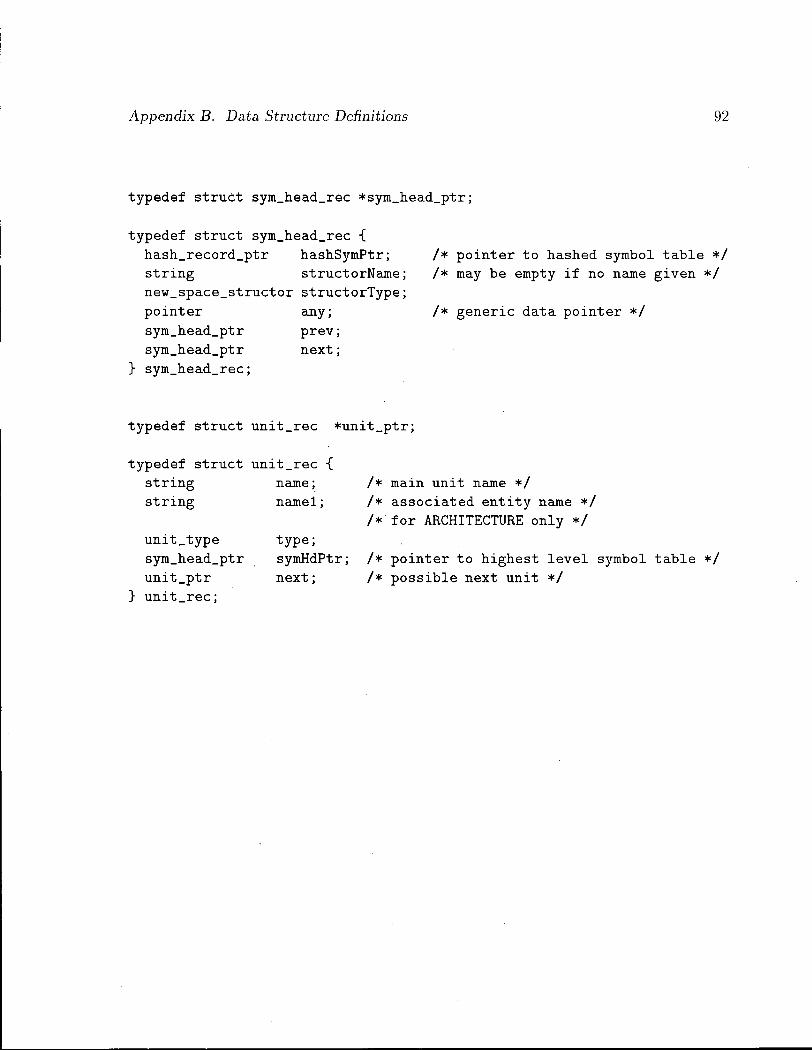
Appendix B. Data Structure Definitions 92
typedef struct sym_head_rec *sym_head_ptr;
typedef struct sym_head_rec { hash_record_ptr hashSymPtr; string structorName; new_space_structor structorType; pointer any; sym_head_ptr prev; sym_head_ptr next;
} sym_head_rec;
/* pointer to hashed symbol table */ /* may be empty i f no name given */
/* generic data pointer */
typedef struct unit_rec *unit_ptr;
typedef struct unit_rec { string string
unit_type sym_head_ptr unit_ptr unit_rec;
name; namel;
type; symHdPtr; next;
/* main unit name */ /* associated entity name */ /•'for ARCHITECTURE only */
/* pointer to highest level symbol table */ /* possible next unit */

A p p e n d i x C
L i b r a r y R o u t i n e Spec i f i c a t i ons
C l P a r s e T r ee B u i l d i n g
node_ptr M a k T o k e n L e a f (node_type type, int token, int line)
M a k T o k e n L e a f creates a leaf node for a token value (Int) token wi th type
type. Line indicates the line number where the token appears in a source
program.
node.ptr M a k S t r L e a f (node_type type, string str, int line)
M a k S t r L e a f creates a leaf node for a string. Type and line have the same
meanings as in M a k T o k e n L e a f .
node_ptr M a k J L A r g (node_type type, int token, int line, node_ptr argl )
M a k _ l A r g makes a construct tree with 1 argument. Token is the code
for this construct, and line denotes the starting location of the construct
in a source program.
node_ptr M a k _ 2 A r g (node_type type, int token, int line, node_ptr a rg l , node_ptr arg2)
M a k _ 2 A r g makes a construct tree with 2 arguments.
node_ptr M a k _ 3 A r g (node.type type, int token, int line, node.ptr a rg l , node_ptr arg2, node_ptr arg3)
M a k _ 3 A r g makes a construct tree wi th 3 argument.
93

Appendix C. Library Routine Specifications
node_ptr M a k _ 4 A r g (node_type type, int token, int line, node_ptr a rg l , node_ptr arg2, node_ptr arg3, node_ptr arg4)
M a k _ 4 A r g makes a construct tree wi th 4 arguments.
node_ptr M a k _ 5 A r g (node_type type, int token, int line, node_ptr a rg l , node_ptr arg2, node_ptr arg3, node_ptr arg4, node_ptr arg5)
M a k _ 5 A r g makes a construct tree with 5 arguments.
node_ptr M a k _ 6 A r g (node_type type, int token, int line, node_ptr a rg l , node_ptr arg2, node_ptr arg3, node_ptr arg4, node_ptr arg5, node_ptr arg6)
M a k _ 6 A r g makes a construct tree with 6 arguments.
node_ptr M a k _ 7 A r g (node_type type, int token, int line, node_ptr a rg l , node_ptr arg2, node_ptr arg3, node_ptr arg4, node_ptr arg5, node_ptr arg6, node_ptr arg7)
M a k _ 7 A r g makes a construct tree wi th 7 arguments.
C . 2 List Processing
node_ptr InsertList (node_ptr element, node_ptr oldList)
InsertList inserts element before the head of oldList and returns the re
sulting list.
node_ptr AppendList (node_ptr element, node_ptr oldList)
AppendList appends element to oldList and returns the resulting list.

Appendix C. Library Routine Specifications 95
int L i s t l e n (node_ptr list)
L i s t L e n returns the length of list.
void M a p L i s t (node_ptr list, void (*func) (node_ptr element))
M a p L i s t applies the function func to each element of the list. Bo th
M a p L i s t and func return nothing.
node_ptr N t h l n L i s t (node_ptr list, int n)
N t h l n L i s t returns the n-th element of list.
node_ptr R e v e r s e L i s t (node_ptr list)
R e v e r s e L i s t reverses list and returns the resulting list.
C . 3 A c c e s s o r s t o T y p e Trees
int G e t T y p e (node_ptr typeTree)
G e t T y p e returns the type of the type tree typeTree.
symboLptr G e t B a s e T y p e (node_ptr typeTree)
G e t B a s e T y p e returns the base type of the type tree typeTree.
symboLptr G e t S u b T y p e (node_ptr typeTree)
G e t S u b T y p e returns the subtype of the type tree typeTree.
int G e t D i r e c t i o n (node_ptr scalar Type)
G e t D i r e c t i o n returns the direction of the scalar type scalarTree.

Appendix C. Library Routine Specifications
node_ptr G e t A r r a y E l e m e n t T y p e T r e e (node_ptr arrayTypeTree)
G e t A r r a y E l e m e n t T y p e T r e e returns the element type tree of an array
declared by arrayTypeTree.
node_ptr G e t A r r a y l n d e x L i s t (node_ptr arrayTypeTree)
G e t A r r a y l n d e x L i s t returns the index list of an array declared by array-
Type Tree.
node_ptr G e t N o D i m (node_ptr arrayTypeTree)
G e t N o D i m returns the dimensionality of an array declared by arrayType
Tree.
node_ptr G e t N a m e T y p e T r e e (node_ptr recTypeTree, string name)
G e t N a m e T y p e T r e e returns the type tree associated wi th the given field
name in a record type recTypeTree.
C . 4 A c c e s s o r s to S y m b o l T a b l e s
node_ptr G e t T y p e T r e e (symboLptr symPtr )
G e t T y p e T r e e returns the type tree associated with a type or subtype
declaration symPtr.
int G e t T y p e T y p e (symboLptr symPtr )
G e t T y p e T y p e returns the type of the type tree associated with a type
or subtype declaration symPtr.
symboLptr G e t B a s e T y p e P t r (symboLptr symPtr)

Appendix C. Library Routine Specifications
GetBaseTypePtr returns the base type of the type tree associated with
a type or subtype declaration symPtr.
string GetBaseName (symboLptr.symPtr)
GetBaseName returns the name of the base type tree associated wi th a
type or subtype declaration symPtr.

Appendix D
V H D L Example
This example is extracted from the 32 bit DLX-Processor model written by Peter J . Ashenden. It contains the behavioral description of the A L U of the D L X cpu as well as related packages. The authour of this thesis made some minor modifications to the original description for conciseness. It is provided " A S IS" and is included here just for some readers to get a flavor of what a V H D L program looks like.
— Copyright (C) 1993, Peter J. Ashenden — Mail: Dept. Computer Science
University of Adelaide, SA 5005, Australia e-mail: [email protected]
— This program is free software; you can redistribute i t and/or modify i t under the terms of the GNU General Public License as published by
— the Free Software Foundation; either version 1, or (at your option) any later version.
— This program is distributed in the hope that i t w i l l be useful, — but WITHOUT ANY WARRANTY; without even the implied warranty of — MERCHANTABILITY or FITNESS FOR A PARTICULAR PURPOSE. Seethe — GNU General Public License for more details.
— You should have received a copy of the GNU General Public License along with this program; i f not, write to the Free Software
— Foundation, Inc.', 675 Mass Ave, Cambridge, MA 02139, USA.
~ $RCSfile: alu.vhdl,v $ $Revision: 2.1 $ $Date: 1993/11/02 18:50:25 $
98

Appendix D. VHDL Example 99
Bit vector arithmetic package specification.
— Does arithmetic and lo g i c a l operations on bit vectors, treating them — as either unsigned or signed (2's complement) integers. Leftmost bit
is most significant or sign b i t , rightmost b i t i s least significant — b i t . Dyadic operations need the two arguments to be of the same
length, however their index ranges and directions may d i f f e r . Results — must be of the same length as the operands.
package bv_arithmetic i s
— Type conversions
— Convert bit vector encoded unsigned integer to natural,
function bv_to_natural (bv : in bit_vector) return natural;
— Convert natural to bit vector encoded unsigned integer. — (length i s used as the size of the result.)
function natural_to_bv (nat : in natural;
length : in natural) return bit_vector;
— Convert bit vector encoded signed integer to integer
function bv_to_integer (bv : in bit_vector) return integer;
— Convert integer to bit vector encoded signed integer. — (length i s used as the size of the result.) function integer_to_bv (int : in integer;

Appendix D. VHDL Example
length : in natural) return bit_vector;
Arithmetic operations
— Signed addition with overflow detection
procedure bv_add (bvl, bv2 : in bit_vector; bv_result : out bit_vector; overflow : out boolean);
— Signed addition without overflow detection
function "+" (bvl, bv2 : in bit_vector) return bit_vector;
— Signed subtraction with overflow detection
procedure bv_sub (bvl, bv2 : in bit_vector; bv_result : out bit_vector; overflow : out boolean);
— Signed subtraction without overflow detection
function "-" (bvl, bv2 : in bit_vector) return bit_vector;
— Unsigned addition with overflow detection
procedure bv_addu (bvl, bv2 : in bit_vector; bv_result : out bit_vector; overflow : out boolean);
— Unsigned addition without overflow detection
procedure bv_addu (bvl, bv2 : in bit_vector; bv_result : out bit_vector);
— Unsigned subtraction with overflow detection

Appendix D. VHDL Example
procedure bv_subu (bvl, bv2 : in bit_vector; bv_result : out bit_vector; overflow : out boolean);
— Unsigned subtraction without overflow detection
procedure bv_subu (bvl, bv2 : i n bit_vector; bv_result : out bit_vector);
— Signed negation with overflow detection
procedure bv_neg (bv : in bit_vector; bv_result : out bit_vector; overflow : out boolean);
— Signed negation without overflow detection
function "-" (bv : in bit_vector) return bit_vector;
— Signed multiplication with overflow detection
procedure bv_mult (bvl, bv2 : in bit_vector; bv_result : out bit_vector; overflow : out boolean);
— Signed multiplication without overflow detection
function "*" (bvl, bv2 : in bit_vector) return bit_vect
— Unsigned multiplication with overflow detection
procedure bv_multu (bvl, bv2 : in bit_vector; bv_result : out bit_vector; overflow : out boolean);
— Unsigned multiplication without overflow detection
procedure bv_multu (bvl, bv2 : i n bit_vector; bv_result : out bit_vector);

Appendix D. VHDL Example
— Signed division with divide by zero and overflow detection
procedure bv_div (bvl, bv2 : in bit_vector; bv_result : out bit_vector; div_by_zero : out boolean; , overflow : out boolean);
— Signed division without divide by zero and overflow detection
function "/" (bvl, bv2 : in bit_vector) return bit_vector;
— Unsigned division with divide by zero detection
procedure bv_divu (bvl, bv2 : in bit_vector; bv_result : out bit_vector; div_by_zero : out boolean);
— Unsigned division without divide by zero detection
procedure bv_divu (bvl, bv2 : in bit_vector; bv_result : out bit_vector);
Logical operators — (Provided for VHDL-87, b u i l t in for VHDL-93)
— Shift l e f t l o g i c a l ( f i l l with '0' bits)
function b v _ s l l (bv : in bit_vector;
shift_count : in natural) return bit_vector;
— Shift right l o g i c a l ( f i l l with '0' bits)
function bv_srl (bv : in bit_vector; shift_count : in natural) return bit_vector;
— Shift right arithmetic ( f i l l with copy of sign bit)

Appendix D. VHDL Example 103
function bv_sra (bv : in bit_vector; shift_count : in natural) return bit_vector;
end bv_arithmetic;
— Package specification for types used in dlx model
package dlx_types i s subtype dlx_word i s bit_vector(0 to 31); — b i t 0 i s msb subtype dlx_halfword is bit_vector(0 to 15); — b i t 0 i s msb subtype dlx.byte i s bit_vector(0 to 7); — b i t 0 i s msb
type dlx_word_array i s array (positive range <>) of dlx_word; function resolve_dlx_word (values : in dlx_word_array) return dlx_word;
subtype dlx_word_bus i s resolve_dlx_word dlx_word;
subtype dlx_address is bit_vector(31 downto 0); — b i t 0 is lsb
end dlx_types;
Package defining types for ALU.
package alu_types i s
type alu_func is (alu_add, alu_addu, alu_sub, alu_subu, alu_and, alu_or, alu_xor, a l u _ s l l , a l u _ s r l , alu_sra, alu_pass_sl, alu_pass_s2);
end alu_types;

Appendix D. VHDL Example
— Entity declaration for ALU.
use work.dlx_types.all, work.alu_types.all;
entity alu is generic (Tpd : Time;
tag : string := " " ) ; port (si : in dlx_word;
s2 : in dlx_word; result : out dlx_word; latch_en : in b i t ; func : in alu_func; zero, negative, overflow : out b i t ) ;
end alu;
Behavioural architecture of ALU.
use work.bv_arithmetic.all; architecture behaviour of alu i s
begin
alu_op: process ( s i , s2, latch_en, func)
variable stored_sl, stored_s2 : dlx_word; variable temp_result : dlx_word; variable temp_overflow : boolean;
begin i f latch_en = '1' then
stored_sl := s i ; stored_s2 := s2;

Appendix D. VHDL Example 105
end i f ; case func i s when alu_pass_sl =>
temp_result := stored_sl; when alu_pass_s2 =>
temp_result := stored_s2; when alu_and =>
temp_result := stored_sl and stored_s2; when alu_or =>
temp_result := stored_sl or stored_s2; when alu_xor =>
temp_result := stored_sl xor stored_s2; when a l u _ s l l =>
temp_result := b v _ s l l (stored_sl, bv_to^.natural (stored_s2(27 to 31))); when al u _ s r l =>
temp_result := bv_srl(stored_sl, bv_to^natural(stored_s2(27 to 31))); when alu_sra =>
temp_result := bv_sra(stored_sl, bv_to_hatural(stored_s2(27 to 31))); when alu_add =>
bv_add(stored_sl, stored_s2, temp_result, temp_overflow); when alu_addu =>
bv_addu(stored_sl, stored_s2, temp_result, temp_overflow); when alu_sub =>
bv_sub(stored_sl, stored_s2, temp_result, temp_overflow); when alu_subu =>
bv_subu(stored_sl, stored_s2, temp_result, temp_overflow); end case; result <= temp_result after Tpd; zero <= bit'val(boolean'pos(temp_result = dlx_word'(X"0000_0000")))
after Tpd; negative <= temp_result(0) after Tpd; overflow <= bit ,val(boolean ,pos(temp_overflow)) after Tpd;
end process alu_op;
end behaviour;