1967-1969 chevy camaro front end, 1968-1972 chevy nova front end 1967 ... · pdf file1967-1969...
TRANSCRIPT
(c) 2010 Total Cost Involved Engineering, Inc. All Rights Reserved.
1
333-TCIE237
1967-1969 Chevy Camaro Front End, 1968-1972 Chevy Nova Front End
1967-1969 Pontiac Firebird Front End Suspension
Installation Instructions 1-855-693-1259
www.totalcostinvolved.com CHECK ALL PARTS INCLUDED IN THIS KIT TO THE PARTS LIST BEFORE INSTALLATION.
IF ANY PIECES ARE MISSING, PLEASE CONTACT: TOTAL COST INVOLVED 855-693-1259
Thank you for choosing TCI Engineering’s Chevy front suspension package. The kit has been designed to not only
allow your Camaro to handle corners, steer and brake better and have more engine compartment room but have that
low sports car stance.
Read and understand these instructions before starting any work
*APPLY ANTI-SEIZE COMPOUND TO THREADS TO AVOID SEIZING AND GALLING OF THREADS
*APPLY THREAD LOCKING COMPOUND TO APPLICABLE FASTENERS TO KEEP THEM FROM VIBRATING
LOOSE
Do not paint or powder coat front clip until you test fit all the parts on the body first. Not all Camaro bodies are exactly
the same and if adjustments need to be made, you will want to do that before you do any painting or powder coating.
This clip is made to be installed without the factory rubber body bushings, it bolts directly to the car without using any
bushings. The original core support bushings are the only bushings that will be reused.
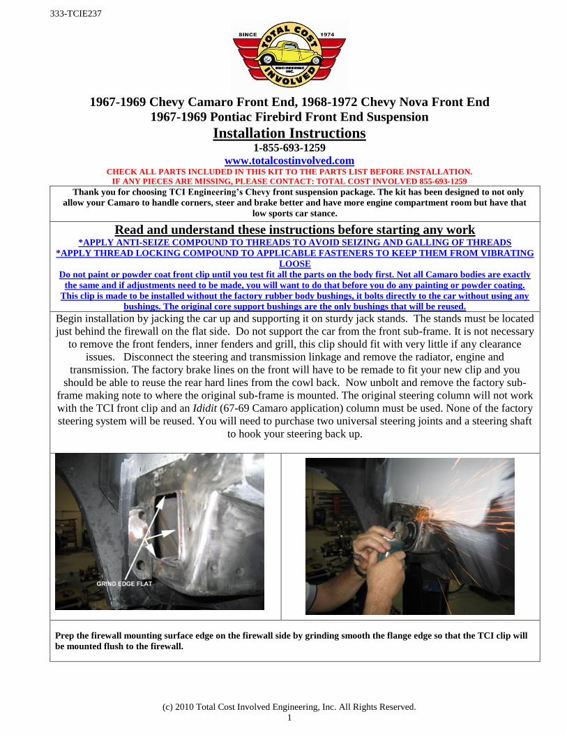
Begin installation by jacking the car up and supporting it on sturdy jack stands. The stands must be located
just behind the firewall on the flat side. Do not support the car from the front sub-frame. It is not necessary
to remove the front fenders, inner fenders and grill, this clip should fit with very little if any clearance
issues. Disconnect the steering and transmission linkage and remove the radiator, engine and
transmission. The factory brake lines on the front will have to be remade to fit your new clip and you
should be able to reuse the rear hard lines from the cowl back. Now unbolt and remove the factory sub-
frame making note to where the original sub-frame is mounted. The original steering column will not work
with the TCI front clip and an Ididit (67-69 Camaro application) column must be used. None of the factory
steering system will be reused. You will need to purchase two universal steering joints and a steering shaft
to hook your steering back up.
Prep the firewall mounting surface edge on the firewall side by grinding smooth the flange edge so that the TCI clip will
be mounted flush to the firewall.
(c) 2010 Total Cost Involved Engineering, Inc. All Rights Reserved.
2
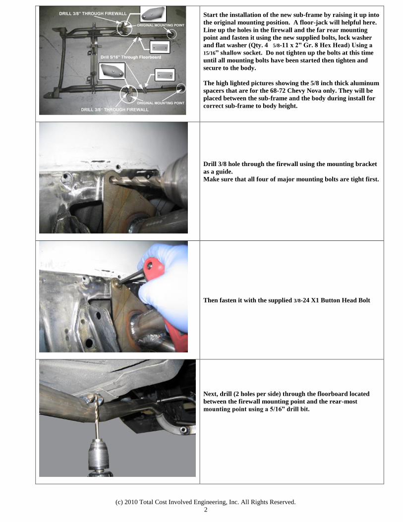
Start the installation of the new sub-frame by raising it up into
the original mounting position. A floor-jack will helpful here.
Line up the holes in the firewall and the far rear mounting
point and fasten it using the new supplied bolts, lock washer
and flat washer (Qty. 4 5/8-11 x 2” Gr. 8 Hex Head) Using a
15/16” shallow socket. Do not tighten up the bolts at this time
until all mounting bolts have been started then tighten and
secure to the body.
The high lighted pictures showing the 5/8 inch thick aluminum
spacers that are for the 68-72 Chevy Nova only. They will be
placed between the sub-frame and the body during install for
correct sub-frame to body height.
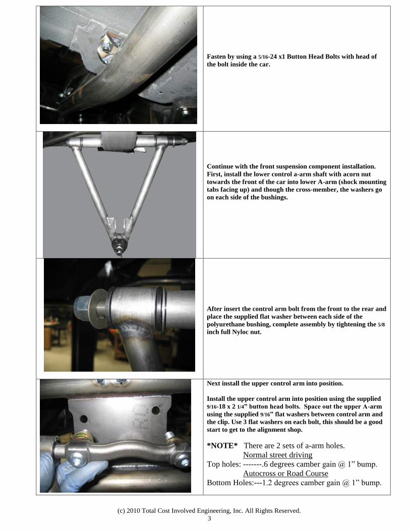
Drill 3/8 hole through the firewall using the mounting bracket
as a guide.
Make sure that all four of major mounting bolts are tight first.
Then fasten it with the supplied 3/8-24 X1 Button Head Bolt
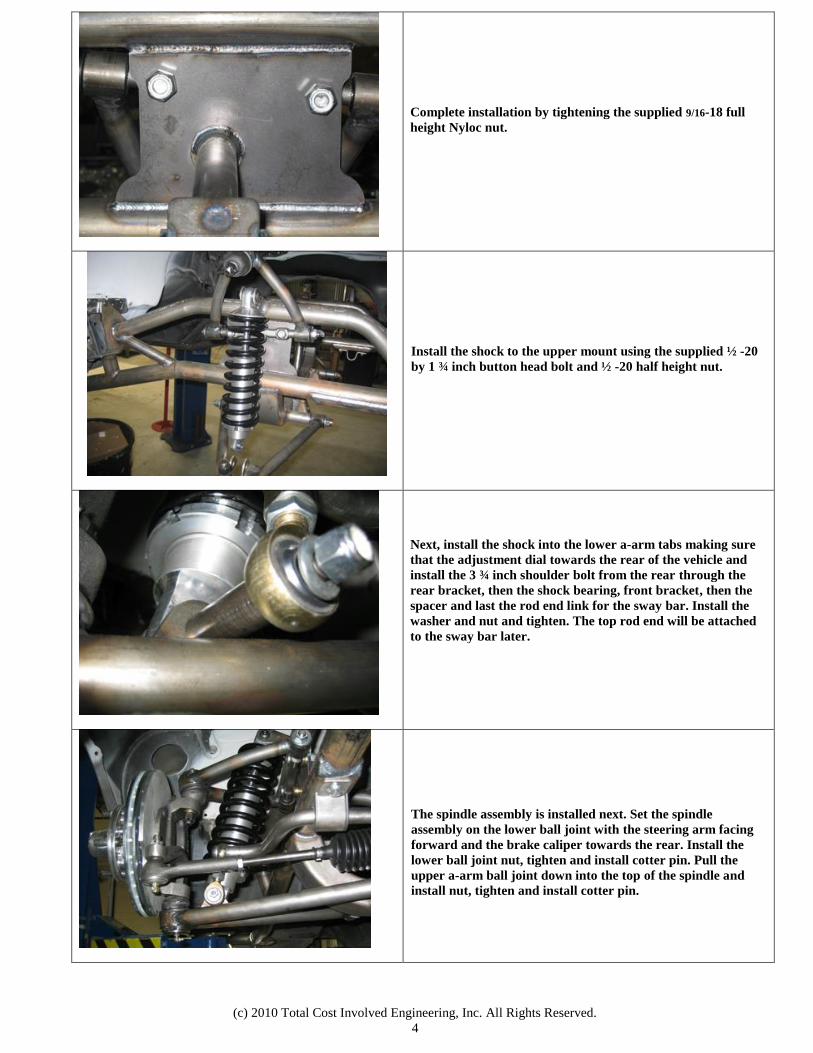
Next, drill (2 holes per side) through the floorboard located
between the firewall mounting point and the rear-most
mounting point using a 5/16” drill bit.
(c) 2010 Total Cost Involved Engineering, Inc. All Rights Reserved.
3
Fasten by using a 5/16-24 x1 Button Head Bolts with head of
the bolt inside the car.
Continue with the front suspension component installation.
First, install the lower control a-arm shaft with acorn nut
towards the front of the car into lower A-arm (shock mounting
tabs facing up) and though the cross-member, the washers go
on each side of the bushings.
After insert the control arm bolt from the front to the rear and
place the supplied flat washer between each side of the
polyurethane bushing, complete assembly by tightening the 5/8
inch full Nyloc nut.
Next install the upper control arm into position.
Install the upper control arm into position using the supplied
9/16-18 x 2 1/4” button head bolts. Space out the upper A-arm
using the supplied 9/16” flat washers between control arm and
the clip. Use 3 flat washers on each bolt, this should be a good
start to get to the alignment shop.
*NOTE* There are 2 sets of a-arm holes.
Normal street driving
Top holes: -------.6 degrees camber gain @ 1” bump.
Autocross or Road Course
Bottom Holes:---1.2 degrees camber gain @ 1” bump.
(c) 2010 Total Cost Involved Engineering, Inc. All Rights Reserved.
4
Complete installation by tightening the supplied 9/16-18 full
height Nyloc nut.
Install the shock to the upper mount using the supplied ½ -20
by 1 ¾ inch button head bolt and ½ -20 half height nut.
Next, install the shock into the lower a-arm tabs making sure
that the adjustment dial towards the rear of the vehicle and
install the 3 ¾ inch shoulder bolt from the rear through the
rear bracket, then the shock bearing, front bracket, then the
spacer and last the rod end link for the sway bar. Install the
washer and nut and tighten. The top rod end will be attached
to the sway bar later.
The spindle assembly is installed next. Set the spindle
assembly on the lower ball joint with the steering arm facing
forward and the brake caliper towards the rear. Install the
lower ball joint nut, tighten and install cotter pin. Pull the
upper a-arm ball joint down into the top of the spindle and
install nut, tighten and install cotter pin.
(c) 2010 Total Cost Involved Engineering, Inc. All Rights Reserved.
5
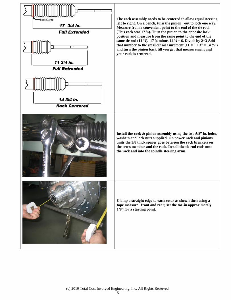
The rack assembly needs to be centered to allow equal steering
left to right. On a bench, turn the pinion out to lock one way.
Measure from a convenient point to the end of the tie rod.
(This rack was 17 ¾). Turn the pinion to the opposite lock
position and measure from the same point to the end of the
same tie rod (11 ¾). 17 ¾ minus 11 ¾ = 6. Divide by 2=3 Add
that number to the smallest measurement (11 ¾” + 3” = 14 ¾”)
and turn the pinion back till you get that measurement and
your rack is centered.
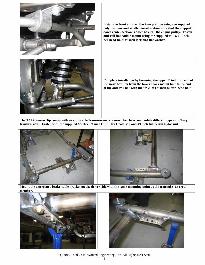
Install the rack & pinion assembly using the two 5/8” in. bolts,
washers and lock nuts supplied. On power rack and pinions
units the 5/8 thick spacer goes between the rack brackets on
the cross member and the rack. Install the tie rod ends onto
the rack and into the spindle steering arms.
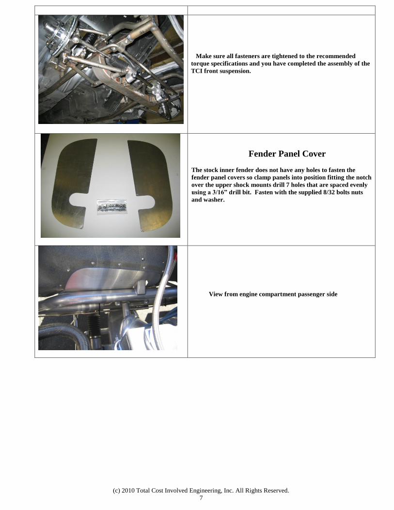
Clamp a straight edge to each rotor as shown then using a
tape measure front and rear; set the toe-in approximately
1/8” for a starting point.
(c) 2010 Total Cost Involved Engineering, Inc. All Rights Reserved.
6
Install the front anti-roll bar into position using the supplied
polyurethane and saddle mount making sure that the stepped
down center section is down to clear the engine pulley. Fasten
anti-roll bar saddle mount using the supplied 3/8-16 x 1 inch
hex head bolt; 3/8 inch lock and flat washer.
Complete installation by fastening the upper ½ inch rod end of
the sway bar link from the lower shock mount bolt to the end
of the anti-roll bar with the 1/2-20 x 1 ½ inch button head bolt.
The TCI Camaro clip comes with an adjustable transmission cross-member to accommodate different types of Chevy
transmissions. Fasten with the supplied 3/8-16 x 1¼ inch Gr. 8 Hex Head Bolt and 3/8 inch full height Nyloc nut.
Mount the emergency brake cable bracket on the driver side with the same mounting point as the transmission cross-
member.
(c) 2010 Total Cost Involved Engineering, Inc. All Rights Reserved.
7
Make sure all fasteners are tightened to the recommended
torque specifications and you have completed the assembly of the
TCI front suspension.
Fender Panel Cover
The stock inner fender does not have any holes to fasten the
fender panel covers so clamp panels into position fitting the notch
over the upper shock mounts drill 7 holes that are spaced evenly
using a 3/16” drill bit. Fasten with the supplied 8/32 bolts nuts
and washer.
View from engine compartment passenger side
(c) 2010 Total Cost Involved Engineering, Inc. All Rights Reserved.
8
View from fender well passenger side
Alignment specifications Caster: Power rack 4-6 degrees positive Manual rack 2-3 degrees positive Camber: 0 Degree(Street) Toe-in: 1/32 to 1/16 inch
*NOTE* Run 1-1.5 degrees negative Camber and zero
toe for Autocross
AXLE STUD SIZES: 4.5” Bolt circle rotors = ½”x20(’75-’80 Ford Granada) 4.75” Bolt circle 10.5” rotors = 12mmx1.5(’82-’87 Camaro) 4.75” Bolt circle 11” rotors = 7/16”x20(’75-’80 Granada redrilled) ALL Wilwood hubs = 1/2”x20
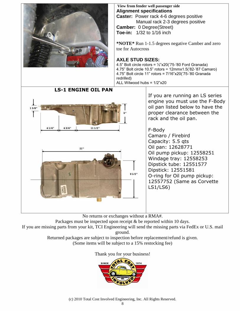
LS-1 ENGINE OIL PAN
If you are running an LS series
engine you must use the F-Body oil pan listed below to have the
proper clearance between the rack and the oil pan.
F-Body
Camaro / Firebird Capacity: 5.5 qts
Oil pan: 12628771
Oil pump pickup: 12558251 Windage tray: 12558253
Dipstick tube: 12551577 Dipstick: 12551581
O-ring for Oil pump pickup: 12557752 (Same as Corvette
LS1/LS6)
No returns or exchanges without a RMA#.
Packages must be inspected upon receipt & be reported within 10 days.
If you are missing parts from your kit, TCI Engineering will send the missing parts via FedEx or U.S. mail
ground.
Returned packages are subject to inspection before replacement/refund is given.
(Some items will be subject to a 15% restocking fee)
Thank you for your business!