a universal direct conversion receiver for · pdf fileconstruct a simple receiver that allows...
TRANSCRIPT
Although you may not be aware of it, the space that surrounds you is filled withbursts of text messages speeding to theirdestinations. No, we’re not referring tomessages produced by teenagers on theircell phones trying to link up at the mall,but rather messages on the shortwavebands that may contain emergency communications, announce a specialevent, or merely consist of friendly greetings exchanged between amateurradio operators located on two differentcontinents. Read on to find out how to construct a simple receiver that allowsyou to “read the mail” using your personal computer.
Shortwave Text MessagesFor decades, the shortwave radio frequencies have
served as a medium for long-distance exchange of data, as well as voice communications. Data signals such asRTTY (radio teletype) and FAX (facsimile) — just to name a few of many that are in use — required expensive, specialized equipment to recover the encoded communications. Because of this, few people outside of the intended recipients could easily retrieve the information contained in these messages. The digital computing revolution has completely changed this situation! Now, almost any PC with a sound card is
capable of recovering this information using freely available software.
In this article, we’ll focus on one particular “digital”mode, known as PSK-31 which was developed to facilitatetext communications between amateur radio operators onshortwave frequencies. We’ll also look at a simple directconversion (DC) receiver design you can build. This receiver converts PSK-31 signals to audio frequencies that are digitized by your sound card and then processeddigitally by your PC in order to recover the text messages.Although the focus of this article is on constructing thereceiver, I’ll also point you to some of the free softwarethat you can download from the Internet for PCs runningWindows to help you quickly get started “reading themail” with PSK-31.
What is PSK-31?The name PSK refers to the “phase shift keying”
modulation technique which means that information isencoded simply by periodically shifting the phase of thetransmitted audio tone in order to encode the information.This gives PSK a characteristic “warble” which you mayhear online yourself at http://aintel.bi.ehu.es/psk31.html.The numerals 31 refer to the data bit rate in Hz (actuallyit’s 31.25 Hz — an exact 1/256 sub-multiple of the 8 kHzsample rate commonly used in PC sound cards); a datarate that is equivalent to what a moderately good typistcan type. Such a low data rate results in an extremely narrow bandwidth for the transmitted signal, and becausenoise is proportional to bandwidth, very low noise as well.Thus, acceptable signal to noise ratios (SNR) are possibleeven with signals that are barely audible to the operator.
PSK-31 encodes text information using a very efficientcode called “varicode,” developed by the designer of PSK-31, Peter Martinez G3PLX. Varicode follows the
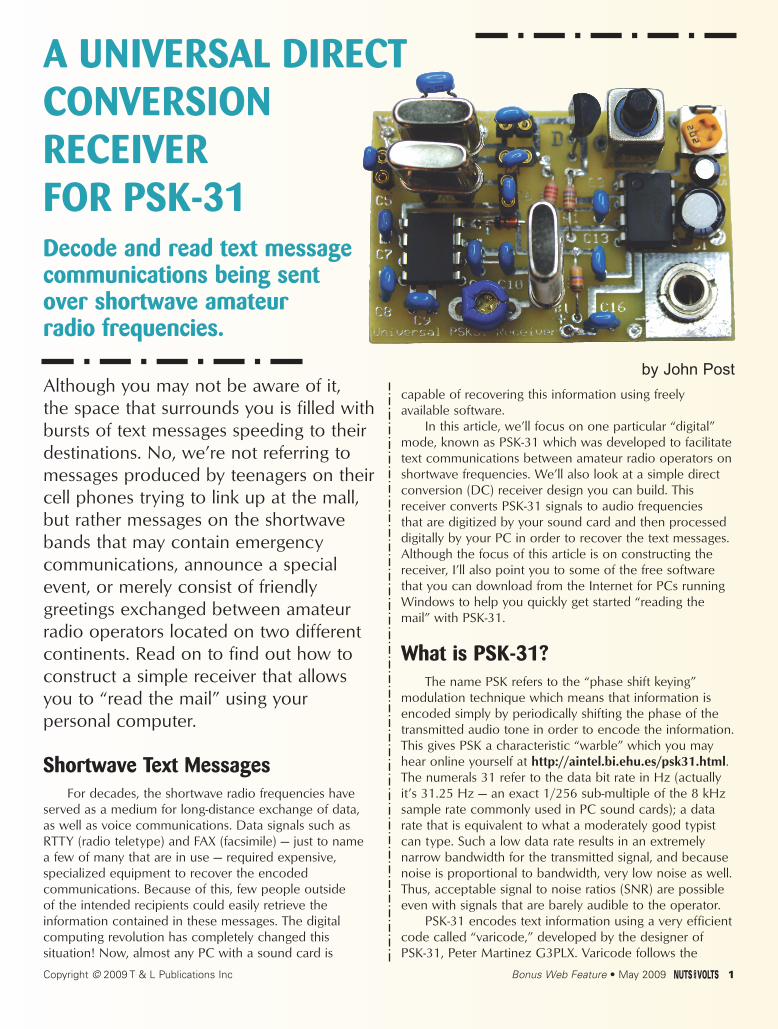
A UNIVERSAL DIRECT CONVERSION RECEIVER FOR PSK-31Decode and read text messagecommunications being sent over shortwave amateur radio frequencies.
by John Post
Copyright © 2009 T & L Publications Inc Bonus Web Feature • May 2009 1
example of Morse code so that shorter codes are assignedto letters of the alphabet that appear more frequently (like e) and longer codes are assigned for infrequentlyused letters (such as z). This minimizes the number of bitsrequired to transmit a given amount of information andmaximizes the code’s efficiency.
Table 1 lists the frequencies where PSK-31 activitiesare concentrated. From my listening experience, the vastmajority of activity takes place on 3.580 and 14.070 MHzin the 80 and 20 meter shortwave bands. Due to the limitations of propagation through the ionosphere, signals on the 80 meter band are strongest late at night —especially in the winter when nights are longer — while 20meter propagation is best late during the day, especially in the summer when days are longer. A quick way ofchecking band conditions is to use a shortwave receiver to listen for the time station WWV or WWVH (whichbroadcasts on 2.5, 5.0, 10.0, 15.0, and 20.0 MHz) at the frequency nearest the one you are interested in.
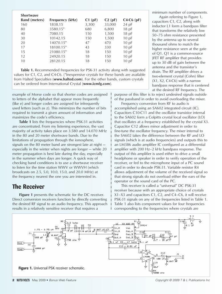
The ReceiverFigure 1 presents the schematic for the DC receiver.
Direct conversion receivers function by directly convertingthe desired RF signal to an audio frequency. This approachresults in a relatively sensitive receiver that requires a
minimum number of components. Again referring to Figure 1,
capacitors C1, C2, along withinductor L1 form a bandpass filterthat transforms the relatively low50–75 ohm resistance presentedby the antenna up to several thousand ohms to match the higher resistance seen at the gateof Q1. Q1 is a common-sourceJFET RF amplifier that provides up to 30 dB of gain between theantenna and the transistor’s drain. The RF amplifier drives atwo-element crystal (Cohn) filter(X1, X2, C4-C6) with a narrowbandpass response that is centeredat the desired RF frequency. The
purpose of this filter is to reject undesired signals outsideof the passband in order to avoid overloading the mixer.
Frequency conversion from RF to audio is accomplished using an SA602 integrated circuit (IC).Capacitors C10-C11 and the oscillator transistor internal to the SA602 form a Colpitts crystal local oscillator (LO)that oscillates at a frequency established by the crystal X3.Capacitor C12 allows minor adjustment in order to fine-tune the oscillator frequency. The mixer internal to the SA602 takes the difference between the RF and LOsignals (which is at audio frequencies) and outputs this toan LM386 audio amplifier IC configured as a differentialamplifier with 200 Hz–2 kHz bandpass response. The output of this amplifier is used either to drive a smallheadphone or speaker in order to verify operation of thereceiver, or fed to the microphone input of a PC soundcard in order to decode PSK-31. Variable resistor R4allows adjustment of the volume of the received signal sothat strong signals do not overload either the ears of theoperator or the sound card of the PC.
This receiver is called a “universal” DC PSK-31 receiver because with an appropriate choice of crystalsX1–X3 and capacitors C1, C2, and C4–C6, it will receivePSK-31 signals on any of the frequencies listed in Table 1.Table 1 also lists component values for four frequenciescorresponding to the frequencies where crystals are
Shortwave Band (meters) Frequency (kHz) C1 (pF) C2 (pF) C4-C6 (pF)160 1838.15 3,300 33,000 24 pF80 3580.15* 680 6,800 18 pF40 7080.15 150 1,500 18 pF30 10142.15 150 1,500 10 pF20 14070.15* 47 470 10 pF17 18100.15* 43 330 10 pF15 21080.15* 18 150 10 pF12 24920.15 18 150 10 pF10 28120.15 18 150 10 pF
Table 1. Recommended frequencies for PSK-31 activity along with suggestedvalues for C1, C2, and C4-C6. (*Inexpensive crystals for these bands are availablefrom Halted Specialties (www.halted.com). For the other bands, custom crystalscan be ordered from International Crystal (www.icmfg.com).
Figure 1. Universal PSK receiver schematic.
2 May 2009 • Bonus Web Feature Copyright © 2009 T & L Publications Inc

readily available. For other frequencies, the crystal frequency must be no more than about 0.06% below the desired PSK operating frequency to allow frequencyadjustment using C11.
The inductor specified will work only for constructingan 80 meter receiver since its adjustment range is just 6%.In order to construct a receiver that will work on all bandslisted in Table 1 (including 80 m), the inductor must adjustbetween 1.75-3.75 µH. An acceptable inductor is available from www.danssmallpartsandkits.net.Inexpensive crystals for 80 m are also available from Digi-Key. A source for suitable crystals for the 15 m, 17 m,and 20 m bands is www.halted.com. Finally, crystals forother frequencies can be specialordered (expensive!) fromInternational Crystal(www.icmfg.com).
Construction, Testing,and Operation
The initial receiver prototype wasconstructed and tested by pluggingthe components into a proto board.Once the operation of the circuit wasverified, a printed circuit board (PCB)was designed using the schematic capture and layout software providedby www.expresspcb.com. The boardfile can be downloaded fromwww.nutsvolts.com.
Figures 2-4 show the top copperlayer, bottom copper layer, and
component layout,respectively, for thereceiver, whileFigure 5 is a photograph of the finished product. In thePCB version of the receiver, sockets were installed toallow rapid switching of components C1, C2, C4-C6, and X1-X3 as necessary for bandswitching.
Once all components are installed, use a multi-meterto verify that the JFET and ICs power up when the battery
DECODING SOFTWARE
Although installing and using PSK-31 software on your PC is not the subject of this article, it is notdifficult to get started. There are many free softwareapplications available for decoding digital signals.You should spend some time researching to deter-mine which software package will work best for yourparticular combination of computer hardware andoperating experience. Someone with modest experi-
ence installing and using new software should be able to install the software and learn enough touse it in an hour or so. Here are a few sites to getyou started:
www.dxzone.com/catalog/Software/PSK31/www.ac6v.com/software.htm#DIGITAL
www.qsl.net/wm2u/psk31.htmlhttp://aintel.bi.ehu.es/psk31.html
www.qsl.net/hamscope/
Figure 5. A printed circuit board implementation of the “universal” PSK-31 receiver. (The battery snap and
antenna connector are not shown in this photo.)
Figure 3. Printed circuit boardbottom copper layout.
Figure 2. Printed circuit boardtop copper layout.
Figure 4. Printed circuit boardcomponent layout. Note thatC17 is not mounted on the PCBbut rather is connected acrossthe terminals of J1
Copyright © 2009 T & L Publications Inc Bonus Web Feature • May 2009 3

is connected. You should measure approximately five voltsat the drain terminal of Q1 and 1.5 volts at the gate andsource terminals of Q1. If these voltages are not obtained,verify component values and connections for R1, R2, andL1 (remember that the inductor is a short at DC!). Next,verify that you have 8.3 volts at pin 8 of U1, and checkthat you have correctly installed D1 if no voltage is measured there. Finally, verify that you have nine volts at pin 6 of U2.
A rapid way of aligning the receiver is through the useof a signal generator and the resistive attenuator shown inFigure 6. Connect the receiver to the attenuator network,plug in a headphone or small speaker to the audio jack,and connect the battery. As you adjust the signal generator to the desired frequency, you should hear anaudio tone from the speaker that changes in frequency asyou adjust the signal generator. With the signal generatorset to the frequency listed in the table, adjust C12 using a non-metallic tool until the audio tone decreases in frequency and then finally vanishes.
If the frequency of the tone won’tdecrease enough, try adding 10-15 pFof capacitance in parallel with C12 inorder to lower the frequency of the LO.Also, your crystals will vary slightly infrequency so try swapping amongthem. Next, adjust L1 to maximize theclarity and volume of the receivedaudio. The final step before decodingdata is to connect the receiver to anantenna appropriate for the shortwaveband of interest and listen for the dis-
tinctive warbling of PSK-31 signals when the shortwavebands are open. If you don’t have a signal generator available, connect the receiver to an antenna and then adjust L1 and C12 forbest reception of the PSK-31 tones when the appropriateband is open.
Once your receiver is operating properly and you’veinstalled PSK-31 decoding software on your PC (see sidebar), the final step is to connect the audio output ofthe receiver to the sound card of the PC using an audiopatch cord with 1/8” phone plugs on each end. After youlaunch the software, you should be able to see the PSKsignals on the PC’s display and read the conversation inthe text window. Figure 7 is a screen capture of theHamscope software using output from the receiver shown in Figure 5, configured for the 20 m band.
I hope you have as much fun building and using yourUniversal PSK Receiver as I have had with mine! You may contact me with any questions or comments [email protected]. NV
To antenna
To ground
50
5 k 50 k
Figure 6. Schematic of the signal generator and attenuatornetwork used for final alignment. Select upper resistanceto produce barely audible output to avoid overloading thereceiver.
Figure 7.
Screen capture of
decoded PSK-31
signals produced
by the receiver
shown in Figure 5.
4 May 2009 • Bonus Web Feature Copyright © 2009 T & L Publications Inc
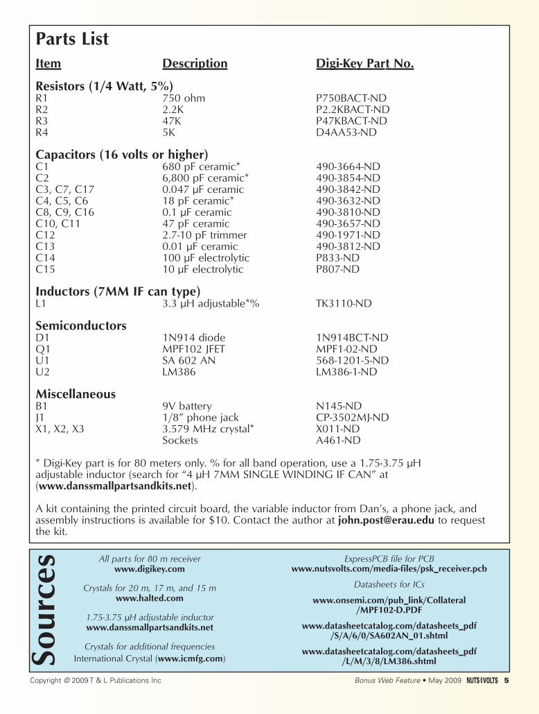
Parts ListItem Description Digi-Key Part No.
Resistors (1/4 Watt, 5%)R1 750 ohm P750BACT-NDR2 2.2K P2.2KBACT-NDR3 47K P47KBACT-NDR4 5K D4AA53-ND
Capacitors (16 volts or higher) C1 680 pF ceramic* 490-3664-NDC2 6,800 pF ceramic* 490-3854-NDC3, C7, C17 0.047 µF ceramic 490-3842-NDC4, C5, C6 18 pF ceramic* 490-3632-NDC8, C9, C16 0.1 µF ceramic 490-3810-NDC10, C11 47 pF ceramic 490-3657-NDC12 2.7-10 pF trimmer 490-1971-NDC13 0.01 µF ceramic 490-3812-NDC14 100 µF electrolytic P833-NDC15 10 µF electrolytic P807-ND
Inductors (7MM IF can type)L1 3.3 µH adjustable*% TK3110-ND
SemiconductorsD1 1N914 diode 1N914BCT-NDQ1 MPF102 JFET MPF1-02-NDU1 SA 602 AN 568-1201-5-NDU2 LM386 LM386-1-ND
MiscellaneousB1 9V battery N145-NDJ1 1/8” phone jack CP-3502MJ-NDX1, X2, X3 3.579 MHz crystal* X011-ND
Sockets A461-ND
* Digi-Key part is for 80 meters only. % for all band operation, use a 1.75-3.75 µH adjustable inductor (search for “4 µH 7MM SINGLE WINDING IF CAN” at (www.danssmallpartsandkits.net).
A kit containing the printed circuit board, the variable inductor from Dan’s, a phone jack, andassembly instructions is available for $10. Contact the author at [email protected] to request the kit.
All parts for 80 m receiverwww.digikey.com
Crystals for 20 m, 17 m, and 15 mwww.halted.com
1.75-3.75 µH adjustable inductor www.danssmallpartsandkits.net
Crystals for additional frequenciesInternational Crystal (www.icmfg.com)
ExpressPCB file for PCBwww.nutsvolts.com/media-files/psk_receiver.pcb
Datasheets for ICs
www.onsemi.com/pub_link/Collateral/MPF102-D.PDF
www.datasheetcatalog.com/datasheets_pdf/S/A/6/0/SA602AN_01.shtml
www.datasheetcatalog.com/datasheets_pdf/L/M/3/8/LM386.shtml
Copyright © 2009 T & L Publications Inc Bonus Web Feature • May 2009 5
Sou
rces