a three-dimensionally ... (di) water with stirring. subsequent vacuum fi ltration con-densed the...
TRANSCRIPT

www.MaterialsViews.comwww.advenergymat.de
FULL P
APER
© 2014 WILEY-VCH Verlag GmbH & Co. KGaA, Weinheim (1 of 10) 1400207wileyonlinelibrary.com
A Three-Dimensionally Interconnected Carbon Nanotube–Conducting Polymer Hydrogel Network for High-Performance Flexible Battery Electrodes
Zheng Chen , John W. F. To , Chao Wang , Zhenda Lu , Nan Liu , Alex Chortos , Lijia Pan , Fei Wei , Yi Cui , * and Zhenan Bao *
DOI: 10.1002/aenm.201400207
sources for wearable devices, artifi cial electronic skins, distributed sensors and other portable electronics. [ 1–4 ] To translate such potentials into reality, one major task is to develop fl exible electrodes with reli-able mechanical properties and excellent electrochemical performances. To realize good mechanical properties, the electrodes should possess strong interaction with the current collector (if applied) or hold a robust scaffold that can sustain mechanical abuse. To achieve high electrochemical per-formance, the electrodes need to preserve effi cient ionic and electronic conductivity during electrode operation. Unfortunately, currently employed batteries and super-capacitors are mainly based on relatively rigid and fragile electrodes and are unsuit-able for fl exible device fabrication because they suffer from structural failure when deformed or folded. [ 5–7 ]
To address this problem, effort has being devoted to designing new structures to render the electrodes fl exible. The most common approaches for fabricating fl ex-
ible electrodes is to directly coat electrode slurries containing active materials, carbon and binder on fl exible substrates such as plastic, [ 4,8 ] textile [ 9–11 ] or paper. [ 3,5 ] While this approach is both simple and effi cient, it utilizes substantial amount of inert
High-performance fl exible energy-storage devices have great potential as power sources for wearable electronics. One major limitation to the realization of these applications is the lack of fl exible electrodes with excellent mechan-ical and electrochemical properties. Currently employed batteries and superca-pacitors are mainly based on electrodes that are not fl exible enough for these purposes. Here, a three-dimensionally interconnected hybrid hydrogel system based on carbon nanotube (CNT)-conductive polymer network architecture is reported for high-performance fl exible lithium ion battery electrodes. Unlike previously reported conducting polymers (e.g., polyaniline, polypyrrole, poly-thiophene), which are mechanically fragile and incompatible with aqueous solution processing, this interpenetrating network of the CNT-conducting polymer hydrogel exibits good mechanical properties, high conductivity, and facile ion transport, leading to facile electrode kinetics and high strain toler-ance during electrode volume change. A high-rate capability for TiO 2 and high cycling stability for SiNP electrodes are reported. Typically, the fl exible TiO 2 electrodes achieved a capacity of 76 mAh g –1 in 40 s of charge/discharge and a high areal capacity of 2.2 mAh cm –2 can be obtained for fl exible SiNP-based electrodes at 0.1C rate. This simple yet effi cient solution process is promising for the fabrication of a variety of high performance fl exible electrodes.
1. Introduction
High-performance, lightweight, fl exible energy-storage devices such as batteries and supercapacitors are potential power
Dr. Z. Chen, J. W. F. To, Dr. C. Wang, Dr. N. Liu, A. Chortos, Prof. Z. Bao Department of Chemical Engineering Stanford University Stanford, CA 94305 , USA E-mail: [email protected] Dr. Z. Lu, Prof. Y. Cui Department of Materials Science and Engineering Stanford University Stanford, CA 94305 , USA E-mail: [email protected] Prof. L. Pan National Laboratory of Microstructures (Nanjing) School of Electronic Science and Engineering Nanjing University Nanjing 210093 , China
Prof. F. Wei Department of Chemical Engineering Tsinghua University Beijing 100084 , P. R. China Prof. Y. Cui Stanford Institute for Materials and Energy Sciences SLAC National Accelerator Laboratory Menlo Park , CA 94205 , USA
Adv. Energy Mater. 2014, 1400207

www.MaterialsViews.comwww.advenergymat.de
FULL
PAPER
© 2014 WILEY-VCH Verlag GmbH & Co. KGaA, Weinheim1400207 (2 of 10) wileyonlinelibrary.com
components that inevitably compromise the device’s volumetric and gravimetric energy density. More importantly, for plastic substrates the effective control of the interface between the sub-strate and active layer remains to be developed; for textile and paper, the active materials may be embedded inside a porous network but their stability in organic electrolyte remains an issue. On the other hand, conducting polymers (CPs) such as polyaniline, polypyrrole and their derivatives, have shown great promise to afford light-weight, fl exible electrodes. However, most electrochemically active CPs again suffer from mechan-ical brittleness, low capacity (<150 mAh g –1 ) and poor chemical or electrochemical stabilities. [ 12 ] Therefore, fl exible electrodes made from CPs is dependent upon its substrate for mechan-ical robustness and, hence, have only a moderate cycling life-time. [ 13–17 ] Furthermore, even though single cable-based devices are fl exible and mechanically robust, but the total charge capacity of the entire device is too low (measured at only a few mF cm –2 or μAh cm –2 ) for practical usage. [ 6,18,19 ]
Another versatile approach toward achieving fl exible elec-trodes is to enable fl exible nanocomposite fi lms by fi ltering solutions containing nanosized active materials and carbon nanotubes (CNTs) or graphene. [ 20–22 ] In such fi lms, the active materials offer charge capacity, while the CNTs or graphene provides both electronic conductivity and mechanical support. However, surface functionalization of CNTs and graphene are required to enable solution processing, hence affecting the elec-tronic conductivity. Thin electrodes made from such composite architectures showed impressive charge storage performances, while thicker electrodes made with the same structure often hold a signifi cantly decreased capacity at increased charge/dis-charge rate, which is attributed to a rapid increase of contact resistance from the CNT or graphene junctions. By using either CNT or graphene only, one can make high-rate fl exible superca-pacitors with reasonable mass loading, but the charge capacity from CNT or graphene is double-layer capacitive in nature, and
is insuffi cient for high-energy devices. [ 23,24 ] In summary, the challenge to effectively fabricate fl exible electrodes for high-per-formance electrochemical energy devices still remains.
2. Results and Discussions
Here, we report a simple yet effi cient aqueous solution process to fabricate high-performance fl exible electrodes using materials comprised of interpenetrating networks of CNT and conducting polymer hydrogel. As illustrated in Figure 1 A, we started with a homogenous precursor solution containing water-stable conducting polymer, namely poly(3,4-ethylenedioxythiophene) doped with poly(4-styrenesulfonate) (PEDOT:PSS), super-long (diameters of 30–80 nm and length of up to 1 mm) CNT and electrochemically active nanoparticles. The CNTs are found to be well dispersed in the aqueous solu-tion containing PEDOT:PSS (Figure 1 B). Addition of gelation agents (e.g., ammonium persulfate (APS)) promoted the com-posite solution to form a hydrogel (Figure 1 C) in about 5 min. The as-formed gel was then re-dispersed by adding more deion-ized (DI) water with stirring. Subsequent vacuum fi ltration con-densed the hydrogel networks into highly robust and fl exible freestanding composite fi lms, which can then be peeled off and cut into desired size and shape for lithium-ion cell fabrication.
In the matrix, the super-long CNT creates as an ideal scaffold with high mechanical robustness and long-range conductivity. Our control experiment using multiwalled CNTs (diameters of 30–80 nm, length of 20–30 μm) failed to produce a free-standing, fl exible fi lm with a similar loading of active nano-particles, which indicates that longer CNT is essential to ensure mechanical robustness of the composite fi lm. Electrochemically active nanoparticles were chosen from a vast library of recently reported energy storage system. [ 25,26 ] With factors such as low cost, abundance and environmental friendliness, we chose
Adv. Energy Mater. 2014, 1400207
Figure 1. A) Schematic of the aqueous solution process to fabricate fl exible electrodes using active nanoparticles (e.g., TiO 2 or Si nanoparticles), CNT and PEDOT:PSS. B) Photograph of the precursor solution containing TiO 2 nanoparticles, CNT and PEDOT:PSS; the existence of PEDOT:PSS signifi cantly enhanced the dispersion of CNT and improved the homogeneity of the dispersion (Figure S1, Supporting Information). C) Photograph of a composite hydrogel composed of TiO 2 nanoparticles, CNT and PEDOT:PSS. D) Photograph of an example of a fl exible TiO 2 -PEDOT:PSS-CNT fi lm fabricated using the above-described solution process.

www.MaterialsViews.comwww.advenergymat.de
FULL P
APER
© 2014 WILEY-VCH Verlag GmbH & Co. KGaA, Weinheim (3 of 10) 1400207wileyonlinelibrary.com
commercially available TiO 2 and Si nanoparticle (SiNP) to dem-onstrate high-rate and stable lithium-ion battery, respectively. Additionally, water-soluble PEDOT:PSS was used because it has a conjugated backbone that allows effi cient transport of de-local-ized electrons through the π orbital systems, leading to high electronic conductivity (10–1000 S cm –1 ), [ 27,28 ] which is ideal for electrode applications. In contrast, most of the other CPs have lower electronic conductivity and are diffi cult to process in aqueous solution due to their low solubility. [ 12,29 ] Moreover, the PSS can enhance the dispersion of CNT in water, presumably through non-covalent stabilization due to a polymer “wrapping” mechanism where the hydrophobic part of the polymer chain covers the CNT surface and the polar hydrophilic part interacts with water to dissociate the CNT bundles. [ 30 ] The signifi cantly improved CNT dispersion using PEDOT:PSS can be clearly observed by comparing with another dispersion in which no PEDOT:PSS was present (Figure S1, Supporting Information). A better dispersion provides more uniform distribution of CNT in the composite fi lm, resulting in better mechanical property and higher conductivity. At the same time, nanoparticles that were dispersed in water tend to form numerous aggregates (or clusters) due to van der Waals forces or electrostatic interac-tions. [ 31 ] Such nanoparticle clusters can be then easily wrapped by the dispersed PEDOT:PSS, again due to hydrophobic-hydro-philic interactions. The subsequent gelation process, initiated by electrostatic interaction between cations, e.g. NH 4 + , and negatively charged PSS, stabilizes the conducting polymer-CNT network where polymer-wrapped nanoparticle clusters are embedded within. Filtration processes further strengthens such composite network and creates a 3D interconnected conduc-tive hydrogel-CNT architecture with outstanding electrical and mechanical properties (Figure 1 C).
We should also mention that previous work on PEDOT:PSS/CNT composites focused mainly on thin fi lms (<1 μm) for photovoltaic applications. [ 32 ] Although a thick PEDOT:PSS/CNT fi lm was used, its specifi c charge capacity was too low due to the device's small charge capacity from both PEDOT:PSS and CNT. [ 33 ] In contrast, our hydrogel approach allows us to pro-cess signifi cantly more complicated systems by incorporating a variety of active materials, leading to a CNT-conducting polymer hydrogel network structure with critical features that have not been achieved before. These include: i) the long CNT scaf-fold provides global electron transport pathways and excellent mechanical robustness; ii) the conducting polymer provides high local conductivity by minimizing contact resistance from nanoparticles and CNTs; iii) the entangled network of CNTs and polymers synergistically provides excellent mechanical robust-ness and high conductivity which otherwise cannot be achieved without polymer wrapping; iv) the effective incorporation of elec-trochemically active particles signifi cantly increases the charge capacity; and v) the network structure creates interconnected channels for effective ion transport and small nanoparticles offer short solid-state diffusion length. These advantageous character-istics have allowed us to fabricate thick, fl exible electrodes with high mechanical robustness and high electrochemical activity.
TiO 2 nanoparticles were fi rst used as an active material to fabricate high-rate fl exible lithium electrodes. Anatase TiO 2 has been studied as a promising electrode material for safe lithium storage due to its moderate voltage window. [ 25 ] Recent studies
suggest that signifi cant pseudocapacitive effect occurs on nano-particulate or mesoporous TiO 2 due to increased surface effect compared with bulk structures, which dramatically increase the rate performance. However, such an effect can only be main-tained within thin fi lm electrodes due to the low conductivity of TiO 2 (10 −3 to 10 −8 S cm –1 ). [ 34–37 ] Nevertheless, our water-based synthetic strategy allowed us to successfully fabricate fl exible thick TiO 2 composite electrodes (TiO 2 -PEDOT:PSS-CNT) with high rate capability and high areal capacity.
Figure 2 A shows a representative scanning electron micros-copy (SEM) image of the fl exible TiO 2 -PEDOT:PSS-CNT fi lm, which exhibits a network structure formed by interpenetration of long CNTs and PEDOT:PSS. The composition of the fi lm can be easily tuned by simply varying the ratio of each constituent; in which we have focused on a composition of 57%-TiO 2 , 28%-CNT and 15%-polymer (by weight) for this work. Although porous fea-tures can be clearly recognized, the fi lm is relatively dense due to the fi ltration and polymer wrapping. Numerous TiO 2 nanopar-ticle clusters are surrounded by CNT network, forming intimate interfaces with each other. Figure 2 B shows the cross-sectional SEM image of the fi lm, indicating a fi lm thickness of ≈20 μm. According to the areal mass loading (2.8 mg cm –2 ), the average density of the fi lm is ≈1.4 g cm –3 . It corresponds to a porosity of ≈45% for the composite. This packing density is signifi cantly higher than P25 (0.108 g cm –3 ) and meso-TiO 2 (0.714 g cm –3 ), as reported previously. [ 38 ] Such a high density is consistent with the surface topography shown in Figure 2 A. A high-resolution SEM image of a selected area in the cross section reveals a unique multilayered structure where CNTs were stretched out from the network (Figure 2 C). We note that large CNT bundles were not observed from the cross-sectional images, which further con-fi rms the facile dispersion of CNT with the aid of PEDOT:PSS. In addition, the obtained transmission electron microscopy (TEM) image (Figure 2 D) clearly shows the TiO 2 clusters pen-etrated by CNTs. Closer observation using TEM (Figure 2 E and Supporting Information Figure S2) clearly shows the effective coating of PEDOT:PSS on the surface of TiO 2 particle. To further elucidate how the PEDOT:PSS interacts with CNT and TiO 2 , elemental mapping was performed using scanning transmis-sion electron microscopy (STEM) energy-dispersive X-ray (EDX) spectroscopy technique. As shown in Figure 2 F, the distribu-tion of CNT, TiO 2 and PEDOT:PSS is indicated by C-K, Ti-K and S/C-K mapping, respectively. The uniform distribution of each element suggests that PEDOT:PSS were wrapped on the TiO 2 surface and have penetrated through the CNT network. Thus, the effective CNT-polymer hydrogel network and conducting wrapping have provided thick electrodes with desired electrical and mechanical properties.
To enable fl exible electrode applications, it is important to correlate the electrical and mechanical properties of the com-posite fi lm. Direct measurement of the conductivity using 4-point probe shows a high conductivity of 215 S cm –1 for the TiO 2 -PEDOT:PSS-CNT fi lm. This conductivity is only slightly lower than that of the PEDOT:PSS-CNT fi lm (measured at 950 S cm –1 ), as made by a similar process, since a large frac-tion (57 wt%) of TiO 2 nanoparticles were incorporated into the conductive network. To investigate the relationship between electrical and mechanical properties, the resistance of a typical TiO 2 -PEDOT:PSS-CNT fi lm was monitored under
Adv. Energy Mater. 2014, 1400207

www.MaterialsViews.comwww.advenergymat.de
FULL
PAPER
© 2014 WILEY-VCH Verlag GmbH & Co. KGaA, Weinheim1400207 (4 of 10) wileyonlinelibrary.com
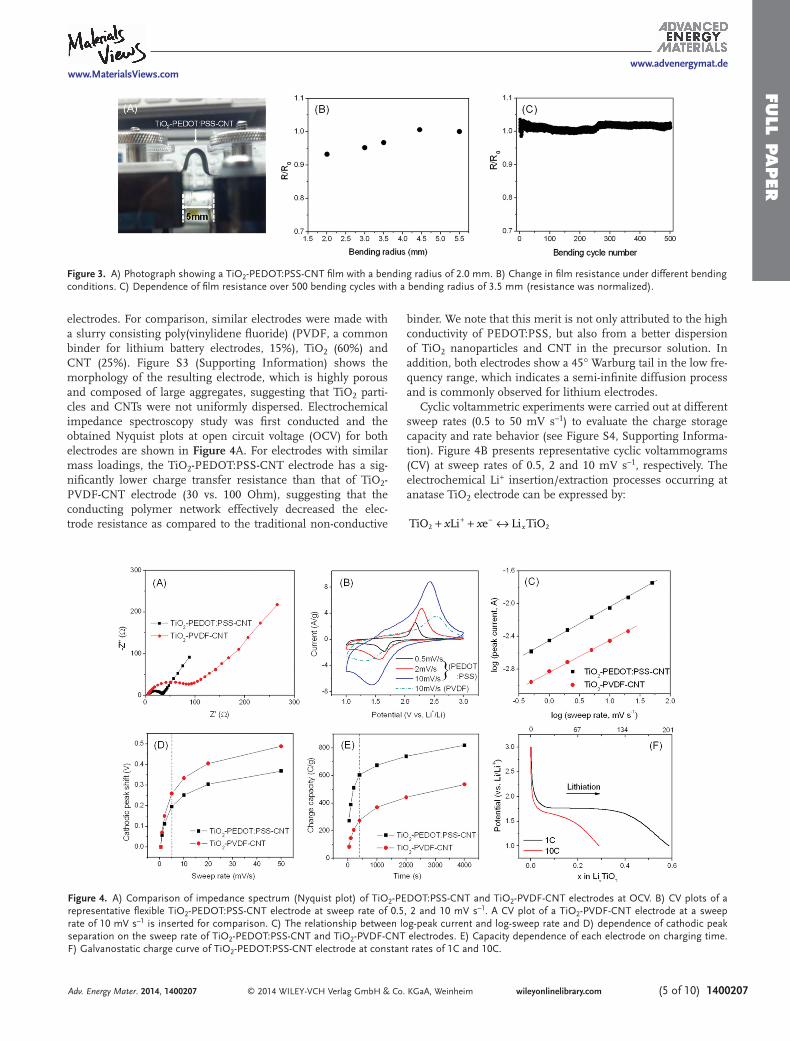
different bending conditions. Figure 3 A shows a fi lm under a bending radius of 2.0 mm, which illustrates its superior fl ex-ibility. While the resistance of the fi lm was stable under slight bending (radius >4.5 mm), we observed that further bending of the fi lm resulted in decreased resistance. As shown in Figure 3 B, the fi lm resistance decreased by ≈8% as the bending radius was decreased from 4.5 to 2.0 mm. This could be due to better contacts in the compressed polymer-CNT network upon bending. In addition, our electrode fi lm was constructed by the superlong CNT entanglement and polymer wrapping. The PEDOT:PSS can easily wrap around the CNT junctions due to
capillary force, which prevents the CNT separation and retains conductivity during bending. Furthermore, this fi lm is highly robust under repeated bending cycles. As shown in Figure 3 C, the fi lm resistance shows negligible change after 500 bending cycles at a bending radius of 3.5 mm, indicating its good overall mechanical property.
The highly conductive, robust CNT-polymer network pro-vides the TiO 2 electrodes with superior rate performance. To characterize the electrochemical performance, the TiO 2 -PEDOT:PSS-CNT electrodes were assembled into 2032-type coin cells using lithium disc as both the counter and reference
Adv. Energy Mater. 2014, 1400207
Figure 2. A) SEM image of the surface view of a representative TiO 2 -PEDOT:PSS-CNT fi lm electrode. The CNT network penetrates through the whole fi lm and TiO 2 NPs form clusters that are embraced by CNT pathways. B) Low and C) high magnifi cation SEM images of the cross-section view of the TiO 2 -PEDOT:PSS-CNT fi lm electrode. A typical fi lm has a thickness of ≈20 μm. The CNT backbones can be clearly observed. D) TEM image of the composite fi lm showing a typical TiO 2 cluster and the CNT network. E) TEM image showing the wrapping of PEDOT:PSS on the surface of a TiO 2 particle. F) Elemental mapping showing the distribution of CNT, PEDOT:PSS and TiO 2 nanoparticles (up-left: spectrum image scanning, up-right: C-K mapping, bottom-left: Ti-K mapping, bottom-right: S-K mapping)
www.MaterialsViews.comwww.advenergymat.de
FULL P
APER
© 2014 WILEY-VCH Verlag GmbH & Co. KGaA, Weinheim (5 of 10) 1400207wileyonlinelibrary.com
electrodes. For comparison, similar electrodes were made with a slurry consisting poly(vinylidene fl uoride) (PVDF, a common binder for lithium battery electrodes, 15%), TiO 2 (60%) and CNT (25%). Figure S3 (Supporting Information) shows the morphology of the resulting electrode, which is highly porous and composed of large aggregates, suggesting that TiO 2 parti-cles and CNTs were not uniformly dispersed. Electrochemical impedance spectroscopy study was fi rst conducted and the obtained Nyquist plots at open circuit voltage (OCV) for both electrodes are shown in Figure 4 A. For electrodes with similar mass loadings, the TiO 2 -PEDOT:PSS-CNT electrode has a sig-nifi cantly lower charge transfer resistance than that of TiO 2 -PVDF-CNT electrode (30 vs. 100 Ohm), suggesting that the conducting polymer network effectively decreased the elec-trode resistance as compared to the traditional non-conductive
binder. We note that this merit is not only attributed to the high conductivity of PEDOT:PSS, but also from a better dispersion of TiO 2 nanoparticles and CNT in the precursor solution. In addition, both electrodes show a 45° Warburg tail in the low fre-quency range, which indicates a semi-infi nite diffusion process and is commonly observed for lithium electrodes.
Cyclic voltammetric experiments were carried out at different sweep rates (0.5 to 50 mV s –1 ) to evaluate the charge storage capacity and rate behavior (see Figure S4, Supporting Informa-tion). Figure 4 B presents representative cyclic voltammograms (CV) at sweep rates of 0.5, 2 and 10 mV s –1 , respectively. The electrochemical Li + insertion/extraction processes occurring at anatase TiO 2 electrode can be expressed by:
x x xTiO Li e Li TiO2 2+ + ↔+ −
Adv. Energy Mater. 2014, 1400207
Figure 3. A) Photograph showing a TiO 2 -PEDOT:PSS-CNT fi lm with a bending radius of 2.0 mm. B) Change in fi lm resistance under different bending conditions. C) Dependence of fi lm resistance over 500 bending cycles with a bending radius of 3.5 mm (resistance was normalized).
Figure 4. A) Comparison of impedance spectrum (Nyquist plot) of TiO 2 -PEDOT:PSS-CNT and TiO 2 -PVDF-CNT electrodes at OCV. B) CV plots of a representative fl exible TiO 2 -PEDOT:PSS-CNT electrode at sweep rate of 0.5, 2 and 10 mV s –1 . A CV plot of a TiO 2 -PVDF-CNT electrode at a sweep rate of 10 mV s –1 is inserted for comparison. C) The relationship between log-peak current and log-sweep rate and D) dependence of cathodic peak separation on the sweep rate of TiO 2 -PEDOT:PSS-CNT and TiO 2 -PVDF-CNT electrodes. E) Capacity dependence of each electrode on charging time. F) Galvanostatic charge curve of TiO 2 -PEDOT:PSS-CNT electrode at constant rates of 1C and 10C.

www.MaterialsViews.comwww.advenergymat.de
FULL
PAPER
© 2014 WILEY-VCH Verlag GmbH & Co. KGaA, Weinheim1400207 (6 of 10) wileyonlinelibrary.com
where x is the mole fraction of the inserted lithium ions ( x ≤ 1). [ 39,40 ] For CV at 0.5 mV s –1 , two well-defi ned redox peaks are observed at 1.65 V (cathodic sweep) and 2.17 V (anodic sweep), corresponding to the biphasic transition between tetragonal anatase and orthorhombic lithium titanate and is consistent with typical insertion/extraction behavior of lithium in TiO 2 . [ 34,39 ] As the sweep rate increases, these current peaks were retained, suggesting facile electrode kinetics. The CV curves with large symmetric under-curve areas at high sweep rates (e.g., 10 mV s –1 ) indicated that a signifi cant portion of the charge storage arises from surface reactions. [ 39 ] By comparison, the CV curve at 10 mV s –1 of TiO 2 -PVDF-CNT electrode showed a much lower peak current and smaller under-curve area, sug-gesting a larger polarization and less charge storage capacity.
Quantitative analysis provided a better understanding on the kinetics of different electrodes. Figure 4 C presents a plot of log ( i ) versus log ( v ) from 0.5 to 50 mV s –1 for TiO 2 -PEDOT:PSS-CNT (Figure S4, Supporting Information). The peak at 50 mV s –1 was severely distorted for TiO 2 -PVDF-CNT electrodes due to strong polarization, thus peaks from only 0.5 to 20 mV s –1 were considered (Figure S5, Supporting Informa-tion). Generally, the peak current obeys a power-law as gov-erned by i = av b , where a and b are adjustable values. [ 41 ] A b value of 0.5 or 1 would suggest that charge current was con-trolled by semi-infi nite linear diffusion or surface reaction, respectively. [ 39 ] The b values for PEDOT:PSS- and PVDF-based electrodes are 0.42 and 0.38, respectively, thus confi rming a semi-infi nite diffusion process. These values were less than 0.5 possibly due to thick electrodes where polarization from active material resistance, ohmic contact, pore diffusion resistance, etc. played a large role. [ 42 ] A higher b value for the former elec-trode indicates its less polarization characteristics. Consistently, TiO 2 -PEDOT:PSS-CNT electrode showed a smaller peak voltage shift than that of TiO 2 -PVDF-CNT electrodes at all sweep rates (Figure 4 D), which again verifi ed its better kinetics.
As a result, PEDOT:PSS-based composite electrode delivered more charge under all our studied conditions. Figure 4 E shows the capacity dependence on charging time. TiO 2 -PEDOT:PSS-CNT electrode showed a capacity 820 C g –1 (or 227 mAh g –1 ) at 0.5 mV s –1 (corresponding to a charge/discharge time of 4000 s), signifi cantly higher than that of TiO 2 -PVDF-CNT electrode (537 C g –1 or 149 mAh g –1 ). According to galvanostatic charge/dis-charge measurements, the maximum capacity was ≈230 mAh g –1 at a rate of C/3 (Figure S6, Supporting Information), which was close to our obtained CV test result. Similar CV testing with a PEDOT:PSS-CNT electrode, in absence of active nano-particles, indicated that the conductive components showed negligible charge capacity (Figure S7, Supporting Information). The maximum areal capacity was observed to reach 0.37 mAh cm –2 , which is signifi cantly higher than previously reported values obtained with thin-fi lm TiO 2 electrodes. For example, Hammond et al. [ 35 ] recently reported an aqueous-based layer-by-layer electrostatic self-assembly approach to fabricate thin fi lm TiO 2 /CNT electrodes. The electrodes showed a similar gravi-metric capacity and high-rate capability to TiO 2 -PEDOT:PSS-CNT at a small thickness of ≈1.5 μm, and also resulted in an areal capacity of less than 50 μAh cm –2 . [ 35 ] This value was approximately one order of magnitude smaller than our fl exible TiO 2 composite electrodes. Moreover, the other advantage of
high packing density is the capability to deliver high volumetric capacity. Along with high density of the composite fi lm, the vol-umetric capacity was observed to reach 1.3 mAh cm –3 . Previous TiO 2 electrodes are often based on highly porous structures, thus the volumetric capacity was signifi cantly lower. [ 38 ]
At a very fast sweep rate of 50 mV s –1 (charge/discharge in 40 s), the PEDOT:PSS-based electrode still retained a consider-able capacity of 273 C g –1 (or 76 mAh g –1 ), which is more than three times of the capacity for PVDF-based electrode (85 C g –1 or 24 mAh g –1 ). Figure 4 F shows the representative galvano-static charge curves for TiO 2 -PEDOT:PSS-CNT electrodes at a rate of 1 and 10 C (1C = 170 mA g –1 ), respectively. At slower charge rate of 1 C, the curve shows a clear plateau at 1.75 V. This is due to the biphasic transition as indicated from CV test, and this part contributed a capacity of 101 mAh g –1 . The fol-lowing sloping region also showed a capacity of 100 mAh g –1 , which is mainly from the interfacial lithium storage occurring on the small nanoparticles. [ 43 ] At a 10 C rate, the plateau region is absent and the charge capacity (97 mAh g –1 ) was attributed to a sloping region, indicating better kinetics from the dominating interfacial reaction. Therefore, the high rate capacity obtained from TiO 2 -PEDOT:PSS-CNT electrodes was due to the good retention of interfacial capacity and is thus not diffusion limited. Correspondingly, it was reasoned that the loss of major capacity for TiO 2 -PVDF-CNT was mainly because of a low conductivity in the bulk electrode. These comparative studies indicated that the use of PEDOT:PSS to construct a highly conductive elec-trode can enable high rate performance at high mass loading.
Besides signifi cantly improving rate capability, the PEDOT:PSS-CNT hydrogel network can also enhance the cycling stability of high-capacity anode materials, and to tol-erate large volume change during repeated cycling processes. Using Si nanoparticles (SiNPs), we also demonstrated that the interpenetrating PEDOT:PSS-CNT network can allow us to fab-ricate highly stable Si anode for high energy fl exible lithium ion battery. Among the many candidates for high energy lithium anode, Si has been considered as the most promising one. [ 26 ] However, Si-based anodes nonetheless have several draw-backs, such as ≈300% volume expansion upon lithium inser-tion, which results in fracture and loss of electrical contacts and unstable solid-electrolyte-interphase (SEI) growth on the Si surface. These issues often result in a short cycle life (i.e., only a few cycles) of bulk Si electrodes. Most current research efforts have focused on designing nanostructured or hybrid electrodes to mitigate these problems. [ 26,44 ] Making fl exible Si electrodes using similar strategies also remains unsuccessful. Recent studies suggest that SiNPs can be used to fabricate elec-trodes by using the slurry processes, which are potentially com-patible with current battery manufacturing route. [ 45–48 ] How-ever, these SiNP electrodes are usually thin and non-fl exible. Another major limitation is that their areal capacity is usually low (<0.5 mAh cm –2 ), making them less attractive for practical applications. Using our above described approach in making TiO 2 -PEDOT:PSS-CNT electrode (see Experimental Section), we successfully demonstrated the fabrication of fl exible Si-PEDOT:PSS-CNT electrodes with good cycling stability and high areal capacity reaching 2.2 mAh cm –2 .
Figure 5 A shows a SEM image of Si-PEDOT:PSS-CNT fi lm electrode. The inset shows a digital photograph of a fi lm
Adv. Energy Mater. 2014, 1400207

www.MaterialsViews.comwww.advenergymat.de
FULL P
APER
© 2014 WILEY-VCH Verlag GmbH & Co. KGaA, Weinheim (7 of 10) 1400207wileyonlinelibrary.com
electrode with good fl exibility. The SiNPs have a relatively broad size distribution, mainly in between 50 to 200 nm. Similar to TiO 2 -PEDOT:PSS-CNT, a CNT network penetrating through SiNP clusters can clearly be observed. Figure 5 B displays the high-magnifi cation SEM image of the selected area in Figure 5 A. A single Si cluster is observed to be threaded by multiple CNTs. Each SiNP is bound and coated by a glue-like layer, which we con-sider to be a PEDOT:PSS coating (Figure S8, Supporting Information). The TEM image in Figure 5 C shows the intimate threading between CNT network and SiNP cluster and is again consistent with Figure 5 B. Elemental mapping in Figure 5 D clearly reveals the distribution of CNT, SiNP and PEDOT:PSS, indicated by C-K, Si-K and S/C-K mapping, respectively. The larger area indicated by S than Si suggests the wrapping of PEDOT:PSS onto the SiNPs. This is slightly different from the distribution of S in TiO 2 -PEDOT:PSS-CNT, in which a more uniform spread of PEDOT:PSS was observed. This may be attrib-uted to the smaller particle sizes of TiO 2 as compared to the SiNP (30 vs. 50–200 nm).
The lithium storage performance of Si-PEDOT:PSS-CNT was also evaluated using coin cells. The electrodes have a mass loading of ≈2 mg cm –2 , which contained 57% of SiNPs. Figure 6 A shows fi rst fi ve CV
Adv. Energy Mater. 2014, 1400207
Figure 5. A) Low and B) high magnifi cation SEM images of the top surface view of a representa-tive Si-PEDOT:PSS-CNT fi lm electrode. The CNT network penetrates through the whole fi lm and SiNPs form clusters that are embraced by CNT pathways. C) TEM image of the composite fi lm showing SiNPs clusters and CNT network. D) Elemental mapping showing the distribution of CNT, PEDOT:PSS and SiNPs (upper-left: spectrum image scanning, upper-right: C-K mapping, bottom-left: Si-K mapping, bottom-right: S-K mapping).
Figure 6. A) CV plots of a representative fl exible Si-PEDOT:PSS-CNT electrode at a sweep rate of 0.2 mV s –1 on the fi rst 5 cycles. B) 1 st , 2 nd and 100 th cycle galvanostatic charge/discharge curve of an electrode at C/10. C) Cycling stability of a thick Si-PEDOT:PSS-CNT electrode at C/10 rate. Cycling result of a control electrode made by simply mixing Si-PEDOT:PSS with CNT is also presented. Areal capacity is also presented. D) Nyquist plots of Si-PEDOT:PSS-CNT electrode at OCV on fresh electrode and after 4 th , 20 th , and 100 th cycle. E) Rate performance of the Si-PEDOT:PSS-CNT electrode electrodes. F) Comparison of areal capacity between the fl exible Si-PEDOT:PSS-CNT electrode and other SiNP-based or nanostructured Si electrodes reported recently.

www.MaterialsViews.comwww.advenergymat.de
FULL
PAPER
© 2014 WILEY-VCH Verlag GmbH & Co. KGaA, Weinheim1400207 (8 of 10) wileyonlinelibrary.com
cycles of a typical electrode at a potential sweep rate of 0.2 mV s –1 . The cathodic peak at 0.56 V on the fi rst CV curve is due to the SEI layer formation on the relatively high surface area electrode (CNT and Si). This peak disappeared in the following cycles, indicating good stability of such SEI layers. The vol-tammetric current associated with the formation of Li-Si alloy began at ≈0.33 V and increased rapidly below 0.2 V, which is accompanied by the formation of different phases of Li 12 Si 7 and Li 15 Si 4 , respectively. Two anodic peaks (at 0.35 V and 0.55 V) appeared on discharge curve, corresponding to the conversion of amorphous Li x Si to Si. The increase of charge current with cycling can be attributed to a gradual activation of more active SiNPs embedded in the thick electrode. Such a CV feature is consistent with many previously reported Si structures. [ 26,49,50 ]
Figure 6 B presents galvanostatic charge/discharge plots on 1 st , 2 nd and 100 th cycle at a constant rate of C/10. The voltage profi le for the fi rst discharge cycle showed a long fl at plateau, where crystalline Si reacted with lithium to form amorphous Li x Si. A capacity of 2820 mAh g –1 (based on the mass of Si) was achieved during this process. The fi rst discharge capacity was 2180 mAh g –1 , corresponding to a coulombic effi ciency of 77.3%. We note that the capacity from PEDOT:PSS-CNT in the voltage window of 0.01 to 1 V is also negligible (95 mAh g –1 ), when compared with SiNPs (Figure S9, Supporting Informa-tion). The following charge and discharge cycles showed dif-ferent characteristic voltage profi les, which may be due to the de-lithiation and lithiation of amorphous Li x Si and Si, respec-tively. [ 26 ] The second cycle discharge capacity decreased to 2209 mAh g –1 , but the columbic effi ciency was increased to 95.6%. Both the charge and discharge capacities remained stable during the subsequent cycles and a charge capacity of 1802 mAh g –1 was obtained after 100 cycles. The capacity dependence on cycle number was shown in Figure 6 C, in which cycling performance of an electrode made by mixing CNT with PEDOT:PSS coated SiNP was compared. The fl exible Si-PEDOT:PSS-CNT electrode kept ≈90% of its initial capacity while the later electrode lost ≈55% of its capacity. This could be easily understood since the hybrid hydrogel electrodes contain uniformly distributed CNT and intimate polymer wrapping around each component, while the control electrodes contain some large Si-PEDOT aggregates (Figure S10, Supporting Information) and worse dispersed CNT. These drawbacks cause a poor Si-CNT interface, which tends to lose electrical conductivity more easily during cycling, leading to worse cycling performance. In addition, previous work in using SiNP-PEDOT:PSS composite electrode with car-boxymethyl cellulose binder only showed a Si capacity of ≈1200 mAh g –1 , along with 35% loss after 80 cycles. [ 51 ] SEM images (Figure S11, Supporting Information) of the electrodes after charge/discharge cycling show a well-retained CNT network. The PEDOT:PSS and Si NPs cannot be clearly identifi ed due to large structural changes and transformation of crystalline SiNP into amorphous Si, but the cluster-like structures threaded by CNT was preserved. This result reaffi rmed the structural advan-tages in our construction of a mechanically stable 3D interpen-etrating PEDOT:PSS-CNT network, in which the SiNPs were effectively confi ned within a robust conductive framework to enable stable cycling.
Electrochemical impedance measurements provided fur-ther evidence on the stability of the Si-PEDOT:PSS-CNT
electrode during repeated cycling processes. Figure 6 D shows the Nyquist plots of the electrodes at different cycling status at OCV. Each plot consists of a semicircle at high frequency range and a Warburg tail at low frequency range. The former is due to electrolyte resistance and charge-transfer resistance, while the latter represents diffusion-resistance from electrode materials. Using the same cell, a decrease in the semicircle during cycling indicates increased electrode conductivity and composite inter-face during lithiation and de-lithiation. The change of the slope in the Warburg tails was due to a combined effect between the increase of electrode porosity and growth of SEI layer. Overall, the retained small electrode series resistance confi rmed the high robustness of the PEDOT:PSS-CNT network. Besides, the electrodes also displayed good rate capability due to the high conductivity retained under charge/discharge cycling. As shown in Figure 6 E, the electrode was able to preserve a capacity of ≈1200 mAh g –1 at a rate of 1C (or 4.2 A g –1 ). This high rate capability is comparable with other SiNP-based electrodes with much less mass loading. [ 49,50 ]
Real application of batteries requires electrodes with a high areal capacity since the inert components (e.g., current col-lector, separator) contribute a signifi cant part of the whole cell. Importantly, our unique interpenetrating Si-PEDOT:PSS-CNT electrode architecture enabled a high real capacity which has yet been achieved with previously reported SiNP electrodes. As shown in Figure 6 C, the areal capacity reached 2.2 mAh cm –2 with the initial cycle and retained to 1.8 mAh cm –2 during the following 100 cycles. By comparison, previous SiNP and common nanostructured Si electrodes often have an areal capacity of less than 1 mAh cm –2 (Figure 6 F), [ 49,50,52–58 ] which was approximately one fold lower than our electrodes. For example, our group has previously reported ultra-long cycling SiNP electrodes by conformal coating of conductive polyani-line (PAni) on SiNPs, but the areal capacity was only about 0.7 mAh cm –2 (due to the relatively low conductivity of PAni). [ 49 ] Recently, Yu et al. reported a 3D hierarchical ternary SiNP com-posite electrode using polypyrrole (PPy) and single-walled CNT as conductive additives. [ 50 ] They achieved stable cycling of 1000 cycles, but suffered in its low areal capacity (0.4–0.7 mAh cm –2 ). Since our electrodes were constructed by a robust hydrogel net-work of long-CNT and PEDOT:PSS, they were able to maintain high electronic conductivity through the bulk electrodes during cycling. Thus, both high mass loading and high areal capacity can simultaneously be achieved. The realization of such high areal capacity SiNP electrodes using CNT-conducting polymer hydrogel network opens great opportunities to fabricate fl ex-ible, light-weight and high-energy lithium battery for practical applications.
3. Conclusions
In summary, we have successfully developed an aqueous-based solution process for effi cient fabrication of high performance fl exible lithium electrodes using a synergistic combination of conducting polymer solution, CNTs and nanoparticle building blocks. The resulting interpenetrating network of CNT-con-ducting polymer hydrogels provided good mechanical proper-ties, high conductivity and facile ion transport, thus leading to
Adv. Energy Mater. 2014, 1400207

www.MaterialsViews.comwww.advenergymat.de
FULL P
APER
© 2014 WILEY-VCH Verlag GmbH & Co. KGaA, Weinheim (9 of 10) 1400207wileyonlinelibrary.comAdv. Energy Mater. 2014, 1400207
facile electrode kinetics and high strain tolerance during volu-metric changes. Due to these structural merits, we are able to achieve high-rate capability for TiO 2 and high cycling stability for SiNP electrodes. Both electrodes also showed high gravi-metric capacity and high areal capacity, greatly surpassing pre-viously reported nanostructured electrodes with the same active materials. This simple yet effi cient solution process thus pro-vides a promising route towards fabrication of a variety of high performance fl exible electrodes. By optimally coupling both the anode and cathode active materials, we envision that fl exible high rate supercapacitors and high energy lithium battery can hence be afforded for practical applications.
4. Experimental Section Fabrication of Flexible TiO 2 -PEDOT:PSS-CNT and Si-PEDOT:PSS-CNT
Electrodes : To make a fl exible TiO 2 -PEDOT:PSS-CNT fi lm, a hybrid hydrogel was fi rst prepared. Typically, commercial TiO 2 nanoparticles (20 mg, Degussa P25, diameter ≈30 nm, 95% anatase phase) were dispersed in DI-water (5 mL) by sonication and stirring. 1.2% PEDOT:PSS solution (0.4 mL, Clevios PH1000) and superlong-CNTs (10 mg) were added to the above dispersion to make a hydrogel precursor. After mixing for 2 h, APS solution (1 mL, 0.2 g mL –1 ) was added to above precursor solution. In about 5 min, the solution became viscous and gel-like, indicating a hydrogel formation. The hydrogel was further dispersed under stirring by adding 5 mL of DI-water. After stirring for another 2 h, the solution was fi ltrated with a nylon fi lter paper (pore size 0.45 μm) using vacuum fi ltration and washed by DI-water, leading to a fl at fi lm on the fi lter paper. The fi lm was dried under ambient condition and then peeled off from the fi lter paper. To make electrodes, the fi lm was punched into desired sizes and dried at 80 °C under vacuum for 3 h. The fi lm thickness can be easily tuned by changing the amount of the precursor solution, and a typical mass loading of TiO 2 -PEDOT:PSS-CNT composite materials was ≈2.8 mg cm −2 . The electrode density was calculated based on the mass loadings and thickness of the active layers by assuming a bulk density of 2.2, 1.0 and 4.3 g cm –3 for CNT, PEDOT:PSS and TiO 2 , respectively. Si-PEDOT:PSS-CNT electrodes were fabricated in the same way by replacing TiO 2 with SiNPs. For control study, PEDOT:PSS-CNT fi lm was made without adding any inorganic particles into the precursor solution.
Si-PEDOT:PSS/CNT Mixture : To make a mixed Si-PEDOT:PSS/CNT electrodes, a Si-PEDOT:PSS hydrogel was prepared by the same process described above but without adding CNT in the hydrogel precursor. After Si-PEDOT:PSS hydrogel was obtained, CNT was added with stirring and the mixed solution was fi ltered and washed to obtain a fi lm.
Fabrication of TiO 2 -PVDF-CNT Electrodes : A slurry-coating process was used to fabricate TiO 2 -PVDF-CNT electrodes. P25 TiO 2 powder, CNT and PVDF binder were mixed in a mass ratio of 6:2.5:1.5 and homogenized in N -methyl-2-pyrrolidone (NMP) to form slurries. The homogenous slurries were coated on Cu foil substrates and dried at 80 °C for 2 h under vacuum. As-formed electrodes were then calendered and further dried under vacuum at 80 °C for another 12 h. The mass loading was controlled to be 2.5–3 mg cm –2 .
Material Characterization : SEM experiments were conducted on an FEI XL30 Siron SEM with FEG source. To see the real morphology, the Si-cycled PEDOT:PSS-CNT electrodes were washed with acetone followed by 0.1 M HCl to remove the surface SEI layer before imaging. TEM experiments were carried out on a FEI Tecnai G2 F20 X-TWIN operated at 200 kV. Bending test was conducted on a home-made bending/stretching test station. To evaluate electrochemical performance, 2032-type coin cells were assembled in an argon-fi lled glovebox, using Celgard 2500 membrane as the separator. Lithium discs were used as both the counter and reference electrodes, and 1 M LiPF 6 in ethylene carbonate/diethylcarbonate/vinylene carbonate (1:1:0.02 v/v/v, Ferro Corporation) was used as the electrolyte. The CV and electrochemical impedance spectroscopy measurement were performed on a Bio-Logic
VMP3 electrochemical workstation. The Nyquist plots were recorded potentiostatically by applying an AC voltage of 10 mV amplitude in the frequency range of 0.01–100 kHz. Galvanostatic charge/discharge test was conducted on an Arbin 2000 multi-channel battery tester. All electrochemical measurements were carried out at room temperature.
Supporting Information Supporting Information is available from the Wiley Online Library or from the author.
Acknowledgements Z.B. and Y.C. acknowledge funding support from the Precourt Institute for Energy at Stanford University and from the Department of Energy, through the SLAC National Accelerator Laboratory LDRD project, under contract DE-AC02–76SF00515. This work was partially supported by the Assistant Secretary for Energy Effi ciency and Renewable Energy, Offi ce of Vehicle Technologies of the U.S. Department of Energy (contract no. DE-AC02–05CH11231) and the Batteries for Advanced Transportation Technologies (BATT) Program (subcontract no. 6951379).
Received: February 4, 2014 Revised: March 17, 2014
Published online:
[1] H. Nishide , K. Oyaizu , Science 2008 , 319 , 737 . [2] V. L. Pushparaj , M. M. Shaijumon , A. Kumar , S. Murugesan , L. Ci ,
R. Vajtai , R. J. Linhardt , O. Nalamasu , P. M. Ajayan , Proc. Natl. Acad. Sci. USA 2007 , 104 , 13574 .
[3] L. Hu , J. W. Choi , Y. Yang , S. Jeong , F. La Mantia , L.-F. Cui , Y. Cui , Proc. Natl. Acad. Sci. USA 2009 , 106 , 21490 .
[4] M. Koo , K.-I. Park , S. H. Lee , M. Suh , D. Y. Jeon , J. W. Choi , K. Kang , K. J. Lee , Nano Lett. 2012 , 12 , 4810 .
[5] L. Hu , H. Wu , F. La Mantia , Y. Yang , Y. Cui , ACS Nano 2010 , 4 , 5843 . [6] Y. H. Kwon , S.-W. Woo , H.-R. Jung , H. K. Yu , K. Kim , B. H. Oh ,
S. Ahn , S.-Y. Lee , S.-W. Song , J. Cho , H.-C. Shin , J. Y. Kim , Adv. Mater. 2012 , 24 , 5192 .
[7] X. Jia , Z. Chen , A. Suwarnasarn , L. Rice , X. Wang , H. Sohn , Q. Zhang , B. M. Wu , F. Wei , Y. Lu , Energy Environ. Sci. 2012 , 5 , 6845 .
[8] K. Wang , W. Zou , B. Quan , A. Yu , H. Wu , P. Jiang , Z. Wei , Adv. Energy Mater. 2011 , 1 , 1068 .
[9] A. M. Gaikwad , A. M. Zamarayeva , J. Rousseau , H. Chu , I. Derin , D. A. Steingart , Adv. Mater. 2012 , 24 , 5071 .
[10] L. Yuan , X.-H. Lu , X. Xiao , T. Zhai , J. Dai , F. Zhang , B. Hu , X. Wang , L. Gong , J. Chen , C. Hu , Y. Tong , J. Zhou , Z. L. Wang , ACS Nano 2012 , 6 , 656 .
[11] Y.-H. Lee , J.-S. Kim , J Noh , I. Lee , H. J. Kim , S. Choi , J. Seo , S. Jeon , T.-S. Kim , J.-Y. Lee , J. W. Choi , Nano Lett. 2013 , 13 , 5753 .
[12] L. Nyholm , G. Nyström , A. Mihranyan , M. Strømme , Adv. Mater. 2011 , 23 , 3751 .
[13] C. Meng , C. Liu , S. Fan , Electrochem. Commun. 2009 , 11 , 186 . [14] Q. Wu , Y. Xu , Z. Yao , A. Liu , G. Shi , ACS Nano 2010 , 4 , 1963 . [15] C. Wang , W. Zheng , Z. Yue , C. O. Too , G. G. Wallace , Adv. Mater.
2011 , 23 , 3580 . [16] J. Wang , C. Y. Wang , C. O. Too , G. G. Wallace , J. Power Sources 2006 ,
161 , 1458 . [17] L. Yuan , B. Yao , B. Hu , K. Huo , W. Chen , J. Zhou , Energy Environ.
Sci. 2013 , 6 , 470 . [18] Y. Meng , Y. Zhao , C. Hu , H. Cheng , Y. Hu , Z. Zhang , G. Shi , L. Qu ,
Adv. Mater. 2013 , 25 , 2326 .
www.MaterialsViews.comwww.advenergymat.de
FULL
PAPER
© 2014 WILEY-VCH Verlag GmbH & Co. KGaA, Weinheim1400207 (10 of 10) wileyonlinelibrary.com Adv. Energy Mater. 2014, 1400207
[19] K. Wang , Q. Meng , Y. Zhang , Z. Wei , M. Miao , Adv. Mater. 2013 , 25 , 1494 .
[20] Y. Cheng , S. Lu , H. Zhang , C. V. Varanasi , J. Liu , Nano Lett. 2012 , 12 , 4206 .
[21] A. Sumboja , C. Y. Foo , X. Wang , P. S. Lee , Adv. Mater. 2013 , 25 , 2809 .
[22] Y. Meng , K. Wang , Y. Zhang , Z. Wei , Adv. Mater. 2013 , 25 , 6985 . [23] M. Kaempgen , C. K. Chan , J. Ma , Y. Cui , G. Gruner , Nano Lett. 2009 ,
9 , 1872 . [24] F. Liu , S. Song , D. Xue , H. Zhang , Adv. Mater. 2012 , 24 , 1089 . [25] D. Deng , M. G. Kim , J. Y. Lee , J. Cho , Energy Environ. Sci. 2009 , 2 ,
818 . [26] C. K. Chan , H. Peng , G. Liu , K. Mcilwrath , X. F. Zhang ,
R. A. Huggins , Y. Cui , Nat. Nanotechnol. 2008 , 3 , 31 . [27] Y. Xia , J. Ouyang , J. Mater. Chem. 2011 , 21 , 4927 . [28] D. Alemu , H.-Y. Wei , K.-C. Ho , C.-W. Chu , Energy Environ. Sci. 2012 ,
5 , 9662 . [29] J. E. Yoo , K. S. Lee , A. Garcia , J. Tarver , E. D. Gomez , K. Baldwin ,
Y. Sun , H. Meng , T.-Q. Nguyen , Y.-L. Loo , Proc. Natl. Acad. Sci. USA 2010 , 107 , 5712 .
[30] S. Razdan , P. K. Patra , S. Kar , L. Ci , R. Vajtai , A. Kukovecz , Z. Kó nya , I. Kiricsi , P. M. Ajayan , Chem. Mater. 2009 , 21 , 3062 .
[31] E. M. Hotze , T. Phenrat , G. V. Lowry , J. Environ. Qual. 2010 , 39 , 1909 . [32] W. Zhang , B. Zhao , Z. He , X. Zhao , H. Wang , S. Yang , H. Wu ,
Y. Cao , Energy Environ. Sci. 2013 , 6 , 1956 . [33] D. Antiohos , G. Folkes , P. Sherrell , S. Ashraf , G. G. Wallace ,
P. Aitchison , A. T. Harris , J. Chen , A. I. Minett , J. Mater. Chem. 2011 , 21 , 15987 .
[34] T. Brezesinski , J. Wang , J. Polleux , B. Dunn , S. H. Tolbert , J. Am. Chem. Soc. 2009 , 131 , 1802 .
[35] M. N. Hyder , B. M. Gallant , N. J. Shah , Y. Shao-Horn , P. T. Hammond , Nano Lett. 2013 , 13 , 4610 .
[36] I. Abayev , A. Zaban , F. Fabregat-Santiago , J. Bisquert , Physica Status Solidi (a) 2003 , 196 , R4 .
[37] R. Asmatulu , A. Karthikeyan , D. C. Bell , S. Ramanathan , M. J. Aziz , J. Mater. Sci. 2009 , 44 , 4613 .
[38] K. Saravanan , K. Ananthanarayanan , P. Balaya , Energy Environ. Sci. 2010 , 3 , 939 .
[39] J. Wang , J. Polleux , J. Lim , B. Dunn , J. Phys. Chem. C 2007 , 111 , 14925 .
[40] M. Wagemaker , W. J. H. Borghols , F. M. Mulder , J. Am. Chem. Soc. 2007 , 129 , 4323 .
[41] H. Lindstrom , S. Sodergren , A. Solbrand , H. Rensmo , J. Hjelm , A. Hagfeldt , S.-E. Lindquist , J. Phys. Chem. B 1997 , 101 , 7717 .
[42] V. Augustyn , J. Come , M. A. Lowe , J. W. Kim , P.-L. Taberna , S. H. Tolbert , H. D. Abruña , P. Simon , B. Dunn , Nat. Mater. 2013 , 12 , 518 .
[43] J.-Y. Shin , D. Samuelis , J. Maier , Adv. Funct. Mater. 2011 , 21 , 3464 . [44] A. Magasinski , P. Dixon , B. Hertzberg , A. Kvit , J. Ayala , G. Yushin ,
Nat. Mater. 2010 , 9 , 353 . [45] L. B. Hu , H. Wu , S. S. Hong , L. F. Cui , J. R. McDonough , S. Bohy ,
Y. Cui , Chem. Commun. 2011 , 47 , 367 . [46] H. Kim , B. Han , J. Choo , J. Cho , Angew. Chem. Int. Ed. 2008 , 47 ,
10151 . [47] G. Liu , S. Xun , N. Vukmirovic , X. Song , P. Olalde-Velasco ,
H. Zheng , V. S. Battaglia , L. Wang , W. Yang , Adv. Mater. 2011 , 23 , 4679 .
[48] H. Wu , G. Y. Zheng , N. A. Liu , T. J. Carney , Y. Yang , Y. Cui , Nano Lett. 2012 , 12 , 904 .
[49] H. Wu , G. Yu , L. Pan , N. Liu , M. T. McDowell , Z. Bao , Y. Cui , Nat. Commun. 2013 , 4 , 1943 .
[50] B. Liu , P. Soares , C. Checkles , Y. Zhao , G. Yu , Nano Lett. 2013 , 13 , 3414 .
[51] L. Yue , S. Wang , X. Zhao , L. Zhang , J. Mater. Chem. 2012 , 22 , 1094 . [52] Y. Yao , M. T. McDowell , I. Ryu , H. Wu , N. Liu , L. Hu , W. D. Nix ,
Y. Cui , Nano Lett. 2011 , 11 , 2949 . [53] H. Wu , G. Chan , J. W. Choi , I. Ryu , Y. Yao , M. T. McDowell ,
S. W. Lee , A. Jackson , Y. Yang , L. Hu , Y. Cui , Nat. Nanotechnol. 2012 , 7 , 310 .
[54] N. Liu , K. Huo , M. T. McDowell , J. Zhao , Y. Cui , Sci. Rep. 2013 , 3 , 1919 .
[55] B. Wang , X. Li , X. Zhang , B. Luo , Y. Zhang , L. Zhi , Adv. Mater. 2013 , 25 , 3560 .
[56] M.-H. Ryou , J. Kim , I. Lee , S. Kim , Y. K. Jeong , S. Hong , J. H. Ryu , T.-S. Kim , J.-K. Park , H. Lee , J. W. Choi , Adv Mater. 2012 , 25 , 1571 .
[57] X. Zhou , A.-M. Cao , L.-J. Wan , Y.-G. Guo , Nano Res. 2012 , 5 , 845 . [58] M. Wu , X. Xiao , N. Vukmirovic , S. Xun , P. K. Das , X. Song ,
P. Olalde-Velasco , D. Wang , A. Z. Weber , L.-W. Wang , V. S. Battaglia , W. Yang , G. Liu , J. Am. Chem. Soc. 2013 , 135 , 12048 .