a study of multilayer soil-fly ash layered system under
TRANSCRIPT

Introduction
Coal based power plants not only produce ofmillions of mega-watts of power but also millionsof tons of fly ash. Most of the coal based powerplants were set-up with sole aim of powergeneration (Dhar, 2001). As a result ofcontinuous disposal of ash, about 1000 milliontons of ash is estimated as dumped in ash pondsin India and every year 100 million tons of ash isbeing added to this quantity which has alreadyconsumed about 40,000 hectares of precious landfor storage that could have been used foragriculture or habitation (Murthy, 1998; Lambaet al, 2000). Besides the handling problems ofhuge quantity of ash, there are severeenvironmental concerns from rising dust fromash ponds to the near by areas whereby fly ash ispresent not only on dining tables but also in thelungs (Sivapullaiah, 2001). Environmentally safedisposal of large quantity of fly ash is not onlyproblematic but also expensive. Keeping in viewthe gravity of the fly ash disposal problem, globalefforts are mooted to utilize fly ash in bulkquantities. Despite these efforts, hardly 30% ofproduced ash on an average world over and lessthan 10% in India. To reduce the problem of
disposal, efforts are being made to utilize thesame. Bulk uses of fly ash are found in manygeotechnical applications such as embankments,fill behind retaining walls. Reclamation fills anddams etc., due to its low unit weight, lowcompressibility and pozzolanic nature. B.R.Phani and Radhey S. Sharma (2004) studied thatthe plasticity, hydraulic conductivity andswelling properties of the blends (mix of fly ashand expansive soil) decrease and the dry unitweight and strength increase with an increase infly ash content. The strength behaviour of flyashes assumes importance in their use ingeotechnical applications. Through the presentpaper, it has been demonstrated that the fly ashcan be stabilized with clayey soil and used as fillmaterial for land reclamation.
Fly ash, also known as pulverized ash, is a wasteproduct of coal based thermal power plants. TheIndian coal, having relatively low calorific valueof 2500 to 3500 kcal/kg and with high ashcontent of about 45%, generates 70-75 milliontones of fly ash in a year in India, which posseschallenge for its safe disposal. The Delhi MetroRail Cooperation (DMRC, 2005) has opted suchan arrangement in its mass transit system for
73International Journal of Civil Engineerng. Vol. 6, No. 2, June 2008
A study of multilayer soil-fly ash layered system under cyclic loading
M. A. Khan1, A. Usmani2, S.S. Shah3 and H. Abbas4
1Lecturer, Dept of Civil Engineering, Aligarh Muslim University, Aligarh, India2Formerly Post Graduate student, Dept of Civil Engineering, Aligarh Muslim University, Aligarh, India,
3Professor, Dept of Civil Engineering, Aligarh Muslim University, Aligarh, India4Professor, Dept of Civil Engineering, Aligarh Muslim University, Aligarh, India, E-mail address:
Abstract: In the present investigation, the cyclic load deformation behaviour of soil-fly ash layered system isstudied using different intensities of failure load (I = 25%, 50% and 75%) with varying number of cycles (N =10, 50 and 100). An attempt has been made to establish the use of fly ash as a fill material for embankments ofHighways and Railways and to examine the effect of cyclic loading on the layered samples of soil and fly ash.The number of cycles, confining pressures and the intensity of loads at which loading unloading has beenperformed were varied. The resilient modulus, permanent strain and cyclic strength factor are evaluated fromthe test results and compared to show their variation with varying stress levels. The nature of stress-strainrelationship is initially linear for low stress levels and then turns non-linear for high stress levels. The testresults reveal two types of failure mechanisms that demonstrate the dependency of consolidated undrainedshear strength tests of soil-fly ash matrix on the interface characteristics of the layered soils under cyclicloading conditions. Data trends indicate greater stability of layered samples of soil-fly ash matrix in terms offailure load (i) at higher number of loading-unloading cycles, performed at lower intensity of deviatoric stress,and (ii) at lower number of cycles but at higher intensity of deviatoric stress.
Keywords: Layered soils, cyclic loading, triaxial tests, fly ash, shear strength
[ D
ownl
oade
d fr
om ij
ce.iu
st.a
c.ir
on
2022
-03-
13 ]
1 / 17

Delhi. Though the DMRC has started using flyash in layered combination with the locallyavailable soil in embankments but there is nosupporting research for the design of suchembankments or prediction of its mechanicalbehaviour under loads. The detailedinvestigations are, therefore, necessary in order tounderstand the response of the layered system ofsoil and fly ash under repeated loads. The presentwork uses layered combination of fly ash andclayey soil. The advantage of using clayey soil isthat it decreases the permeability, increases thedensity, reduces the compressibility andimproves the shear strength characteristics of flyash.
Cyclic loading is associated with most of thegeotechnical problems, which includes mainlymarine problems involving wave loading,pavement loading in the form of vehicular traffic,earthquake loading etc. The research ondeformation behavior of soils under repeatedloading dates back to 1950s. Seed (1956, 1958and 1960) studied the effect of repeated loadingon the strength and deformation of compactedclay and showed that repeated loading produceda gain of strength which suggests that a roadwaygrows with traffic (Seed et.al. 1995). The mainfactors controlling an embankment’sperformance is its deformation behaviour underloads. Diyaljee and Raymond (1982) establisheda procedure to predict the permanent deformationunder long term repeated loading using the staticstress-strain data and a minimum number ofcycles of repetitive load test data. Probableconditions under cyclic loading are undrainedand constant confining stress. Pumphery andLentz (1986) tested Florida subgrade sand underrepeated loading up to10 and 250 cycles andfound that confining pressure did not causesignificant changes in permanent deformation forlow stress ratios (less than 0.60). However, asubstantial decrease of permanent deformationwas observed for large stress ratios. Severalresearchers (Allen & Thompson, 1974; Brownand Hyde, 1975) have explored the effect ofvariable (cyclic) confining pressure on thedeformation of subgrade soils. Similar results forresilient and permanent strain were reported from
cyclic and constant confining pressure tests,when the constant confining pressure was set tothe average of the cyclic confining pressure(Brown & Hyde, 1975). This suggests that a fixedconfining pressure could be used in repeatedloading tests to get deformation data to simulatethe cyclic confining effects of sub grade soilsunder moving vehicles. The cyclic shearingbehavior of saturated clays has been addressed innumerous publications (Brown et al., 1975;Castro and Christian, 1976). Some investigatorshave suggested the relationships betweenmoisture content, dry density, and the permanentaxial strain accumulation that results fromincreasing number of load cycles (Li and Selig,2001). Studies concerning fly ash utilization forsoil stabilization have been conducted by manyinvestigators. However, there is still a need tofind new uses and to increase utilization so lessash will need to be deposited of. Its use asstabilizer clayey soils has not been investigated toan appreciable extent. Consoli et al. (2001)brought out the effects of compacted soil-fly ash-carbide lime mixtures on strength. Cocka (2001)suggested that the optimum fly ash used forstabilizing the expansive clay can be wellassessed based on the swelling potential. Heshowed that the addition of fly ash to expansiveclay reduces the swelling potential. There wasonly a slight decrease in swelling potential from20 to 25% fly ash additions. The optimum fly ashcontent was found near 20%. The major technicalissues in dealing with fly ash as geotechnicalmaterial are erosion and liquefaction for whichsome studies (Boominathan and Hari, 1999;Trivedi et al, 2000) are carried out previously.Sharma and Fahey (2003) studied that thedeviator stress and deviatoric strain at yieldreduced with increasing number of cycles forcemented sand due to progressive degradation ofbond, which results in significant decrease instiffness. Undrained triaxial tests are performedover a wide range of confining pressure andnormalized cyclic stress.
In present work, an attempt is made to study thecyclic load deformation behaviour of layeredsystem of soil and fly ash under various numbersof cycles and intensity of loads.
74 International Journal of Civil Engineerng. Vol. 6, No. 2, June 2008
[ D
ownl
oade
d fr
om ij
ce.iu
st.a
c.ir
on
2022
-03-
13 ]
2 / 17

Layered soil
Although most of research activities have beenconcentrated on dealing with either single ormixed type of soil deposits occurring in naturalconditions, but uneven availability of suitablegeological material along with environmentalconstraints compels the use of multiple materialsfor the construction of embankment andpavement structures. The interaction betweenlayers of material, having different elastic moduliand deformation behaviour, under cyclic loadinghas a major influence on how each layer and typeof material behaves. The interaction of layerswithin a layered matrix affects its stressdistribution, which in turn affects the total elasticand plastic strains developed within each materialand hence their response to those stresses(Fleming and Rogers, 1995). The stress buildupultimately leads to permanent deformation withinthe pavement. It has now been understood thatthe properties of an element within any one layerofof material in a pavement structure will varywith the magnitude of the applied stress, therelative position of the element and theconfinement provided to the thickness of thelayer and the pavement structure as a whole(Fleming and Rogers 1995). Thus individualstress behaviour of each material together withthe composite behaviour forms important part ofthe study under cyclic loading for a layeredconstruction. Shroff et al (2004) studied toevaluate the failure mechanism of soil-fly ashcomposite mass under three point loading,triaxial loading condition and unconfinedcompression condition on cylindrical specimens.and proved that the soil-fly ash layered systemcan increase the value of cohesion (0 kPa to 69kPa) and % failure strain value (9.5%).
A practical approach of utilization of fly ash inembankments is to have alternate layers of soiland fly ash for which no study is reported inliterature. In the present study, a systematiclaboratory investigation has been carried out byconducting a series of undrained cyclic triaxialcompression tests on layered samples of soil andfly ash, under different intensities of deviatoricfailure load and under varying confining
pressures with a view to establish a relationshipbetween shear strength parameters and cyclicloading conditions.
Resilient Modulus for Soils
Cracking of pavements, which result fromexcessive plastic and repeated elastic deflections,depend upon the resilient properties of thecomponents of pavement. The Subgrade resilientmodulus (Mr) is defined as the repeatedmaximum axial deviator stress ( d) divided byrecoverable axial deformation ( r) that isMr = ( d / r ), which is an importantcharacteristic of the multilayer pavement system.The AASHTO guide for design of pavementstructures (AASTHO 1982) proposed theresilient modulus test to characterize roadbedsoil.
Materials and Method
The soil is obtained from Aligarh located in UttarPradesh province of India whose properties areindicated in Table 1. The soil used in the study iscohesive having liquid limit and plastic limit as32.5% and 22.5% with small angle of internalfriction of 15o.From the plasticity chart, it isconfirmed that the soil is clayey silts. Such typesof soils are not suitable for the construction ofembankment of highways and railways due to itshigh compressibility and very low permeability.Whereas, fly ash is cohesion less ideal materialwhose angle of internal friction is about 26o.Therefore several concentrated efforts are beingmade to understand the possible mechanismsgoverning behaviour of layered system of soiland fly ash under repeated loading in relation toshear strength.
The fly ash used in this investigation is procuredfrom Dadri and Rajghat thermal power plants inIndia. Fly ash collected is dried, sieved throughIS sieve 425 microns and stored in airtightcontainers in the laboratory. The chemical andphysical properties of fly ash are given in Table 2.The fly ash used in the present study is classified
75Mehboob Anwer Khan, Altaf Usmani, Syed Salahuddin Shah, Husain Abbas
[ D
ownl
oade
d fr
om ij
ce.iu
st.a
c.ir
on
2022
-03-
13 ]
3 / 17

76 International Journal of Civil Engineerng. Vol. 6, No. 2, June 2008
Specific gravity 2.7 at 280 CNatural water content 5.0%Optimum moisture content 18.0%Bulk unit weight 21.7 kN/m3
Maximum dry density 18.4 kPa Liquid limit 32.5%Plastic limit 22.5%Plasticity index 10.0%Unit cohesion 68.0 kPa Angle of internal friction 15.0o
Soil classification as per USCS Clayey silts with slight plasticity (ML)
Chemical Properties
Silica (SiO2) 60.03%Alumina oxide (Al2O3) 24.70%Iron oxide ( Fe2O3 ) 9.46%Loss on ignition (LOI) 2.84%Calcium oxide (CaO2 ) 2.29%Magnesium oxide (MgO2) 0.26%Sulpher trioxide (SO3 ) 0.40%Potassium Oxide (K2O) 0. 20%Sodium Oxide (Na2O) 0.30%Physical Properties Specific gravity 1.98 at 280 C Natural water content 2.00%Bulk unit weight 14.93 kN/m3
Optimum moisture content 31.00%Maximum dry Density 11.40 kPa Percent finer than 75� 45.00%Fly ash Classification as per ASTM C-618 Class F - Non-self-cementing
Table 1 Physical Properties of Soil
Table 2 Properties of Fly ash
[ D
ownl
oade
d fr
om ij
ce.iu
st.a
c.ir
on
2022
-03-
13 ]
4 / 17

as Non-self-cementing; class F as per ASTM C-618. The optimum moisture content (OMC) offly ash and soil using standard proctorcompaction test was found to be 31% and 18%respectively. The particle size distribution curveof fly ash and soil are shown in Fig. 1a and 1b.
The triaxial specimens were prepared in a metalmould of 8.4 cm high and 3.9 cm in diameter andcompacted in three equal layers. Each specimenof soil and fly ash was prepared at theircorresponding OMC and statically compactedunder the impact of 25 blows by a minicompactor of 100g weight by a free fall of 15 cm,imparting approximately 0.148 kgm2/s2 ofenergy. The layered system of soil and fly ash canbe compacted in the field at their correspondingOMC to maintain nearly same density as done in
the laboratory.
The size of the sample used was cylindrical, 8.4cm high and 3.9 cm in diameter. In soil-fly ashmatrix, there were alternate layers of soil and flyash. The thickness of fly ash and soil were 2.7and 1.0 cm respectively. The top and bottomlayers in the specimen were that of soil, thus therewere three soil and two fly ash layers The bestoption of number of soil and fly ash layers is 3and 2 because the large amount of fly ash in twolayers can be confined between three layers ofsoils. The binding effect of soil and fly-ash is alsoincreased due to four interfaces of soil and fly ashlayers as shown in Fig. 2. The gross unit weightof soil-fly ash matrix was maintained at 16.8±0.1kN/m3 for all the layered samples. All thesamples have been prepared under similar
77Mehboob Anwer Khan, Altaf Usmani, Syed Salahuddin Shah, Husain Abbas
0
10
20
30
40
50
60
70
80
90
100
0.001 0.01 0.1 1
Perc
ent f
iner
(%
)
Particle size (mm)
0
10
20
30
40
50
60
70
80
90
100
0.0001 0.001 0.01 0.1 1
Perc
enta
ge f
iner
(%
)
Particle size (mm)
Fig. 1a Particle size distribution of fly ash Fig. 1b Particle size distribution curve for clayey soil
d
1� � � ��� ��
3d
d 3
3 9
( A l l d im e n s io n s a r e in m m )
( S o i l )
( F ly a s h )
( S o i l )
( F ly a s h )
( S o i l )
( D ia m e te r )
3�
� = C o n f in in g p r e s s u r e
� �� � � � �1
3
�3
� = D e v ia to r s t r e s s
1 0
2 7
1 0
2 7
1 0
Fig. 2 Free body diagram of sample of soil-fly ash matrix
[ D
ownl
oade
d fr
om ij
ce.iu
st.a
c.ir
on
2022
-03-
13 ]
5 / 17

conditions of compaction to maintain uniformdensity and good reproducibility. Thisarrangement of soil-fly ash matrix has beenadopted keeping in view the fact that the fly ashcannot be placed at the top of embankmentsbecause it will then be exposed to theatmosphere causing the problems of erosion,water pollution like leaching owing to theexistence of alkaline compounds and low shearstrength due to its cohesion less nature. Thedetails of cyclic tests on soil-fly ash matrix aregiven in Table 3.
A strain controlled triaxial shear test machine of5000 kg with proving ring of 250 kg capacity isused for applying the axial load to the specimensof plain soil, plain fly ash and soil-fly ash matrixunder non-cyclic loading as well as stresscontrolled cyclic loading. The tests wereperformed with a strain rate of 0.025 mm/minuteunder consolidated undrained conditions tosimulate the actual ground cyclic conditions.Monotonic tests on plain fly ash and soil sampleswere carried out to explicitly develop a betterunderstanding of the independent stress- strainbehaviour of the constituent materials in thelayered system in response to compressiveloading and for critical comparison of variousparameters.
There are nine sets of stress controlled cyclic loadtests were perform as shown in table 3. One set ofnon-cyclic load test was also performed on thislayered combination. Each set of tests wascarried out at three different confining pressures,
3 = 50, 100 and 150 kPa. Thus a total number ofthirty triaxial shear tests were performedincluding non-cyclic tests on plain soil, plain flyash and soil-fly ash matrix. The intensity of load,I = 25%, 50% and 75% at which loadingunloading of cycles was performed is thepercentage of the deviator load at failure in non-cyclic loading condition. An equal time forloading and relieving, equal to one minute wasadopted for all the cycles. After completing thedesired number of cycles N, the deviator load wasincreased till failure of the specimen. The loadingand unloading of samples under cyclic loads areshown in Fig. 3. The type of cyclic loadingselected for the present study takes into accountthe worst condition of the pavements whichreceive normal traffic flow of lower loadintensity during most part of their life (i.e.number of repetitions of loads of low intensity)but are subjected to a higher intensity of loadcycle like the movement of battle tanks etc. (i.e.high magnitude of load), once in a life time. Thistype of alternative procedure of cyclic testingalso described by Poulos, (1965) providesinformation on the loss/gain of shear strength dueto cyclic loading by critically comparing the ratioof post-cyclic strength to static shear strength ofthe soils.
In another study employing a similar type ofloading, conducted by Matthew et al. (2004),although the cyclic response was studied but theeffect of each individual intensity of cyclic loadwas not studied, i.e. to say a set of desired cycles,was given in increments up to 5% axial strain,
78 International Journal of Civil Engineerng. Vol. 6, No. 2, June 2008
Number of cycles Intensity of repeated load, IN Set-1 Set-2 Set-3 10 25% 50% 75%50 25% 50% 75%
100 25% 50% 75%* Each set of experiment consists of three tests at confining pressure of�3 =
50, 100 and 150 kPa
Table 3 Experiments performed on soil-fly ash matrix*
[ D
ownl
oade
d fr
om ij
ce.iu
st.a
c.ir
on
2022
-03-
13 ]
6 / 17

and then failed monotonically. But in this study,the effect of each individual intensity of failureload was studied up to different number ofdesired cycles and then failed monotonically. It isunderstood that for the practical implementationof the present study, for the design of highwaypavements the value of load intensity, I, could betaken as the ratio of the traffic load intensityunder normal traffic flow condition to themaximum expected traffic load. It is wellunderstood that in such a loading subjectingsimilar samples to different intensities of cyclicstresses, I, the dependence of these strains oncyclic stress level can be plotted. The test ofThiers and Seed (1969) clearly indicates that forclays this loss of strength depends on the amountof cyclic strain relative to the static strain atfailure.
In the present study, vertical axial compression ofspecimen with the change in the deviator loadwas recorded. A uniform failure criterion of peakdeviator stress is adopted for all the samplesduring entire test range.
Mode of Failure
The failure of samples of plain soil is by bulgingat the mid height of the specimen, but in case of
samples of plain fly ash, a very distinct inclinedcrack appeared. For increasing intensity of loads,I and number of cycles, N, it is noticed that thereis a sudden collapse of soil and fly ash layeredsamples due to breaking of cementitiouscompounds.
The following two different types of failuremechanisms were noticed in the layered samplesof soil-fly ash matrix during the experiments:
Failure Mode 1: The failure occurred by bulgingin the sandwiched layers of fly ash. Thephotographs of a sample taken before and afterthe testing are shown in Fig. 4. It is seen thatmany inclined shear failure planes appeared onlyin the sandwiched layers of fly ash in addition totangential cracks from its radial bulging and thefailure planes do not break the interfaces betweensoil and fly ash. This mode of failure wasobserved for samples that recorded an increase inthe deviator stress at failure with increasingnumber of cycles (N), i.e. for samples tested for(a) all values of I and N O 50, and (b) I O 25%and N > 50.
Failure Mode 2: This failure mode also showedbulging at failure, but extended to a greatersurface area. The photographs of a sample takenbefore and after the testing are shown in Fig. 5.
79Mehboob Anwer Khan, Altaf Usmani, Syed Salahuddin Shah, Husain Abbas
LoadingTime
ReliefTime Failure
0 0.5 1.5
Time (min)
I*F/100
Loa
d
= 1, 2, 3,... N
n = cycle number
n = 1 n = 2 n = 3 n = N
1.0 2.0 2.5 3.53.0 4.0 4.5 5.55.0 (2N-2) 2N
Fig. 3 Loading and unloading cycles
[ D
ownl
oade
d fr
om ij
ce.iu
st.a
c.ir
on
2022
-03-
13 ]
7 / 17

An inclined shear failure plane appeared passingthrough the layers of fly ash and extended to thelayer of soil. It can be seen that after I >25%stress level comparatively large strains wererecorded with number of cycles N > 50 indicatingthe possible collapse of the samples This type offailure occurs due to breaking of bond betweenthe interfaces of soil and fly ash.
The difference observed in the two failure modesreflects the resistance of the different materials ofthe layered system to applied stresses. The crackformation in the samples initiated from the flyash layer and extended to the soil layer as theload is increased. When either the intensity ofload (I) is small or the number of cycles aresmall, there is gain in strength of the matrix dueto the confinement of the fly ash layer due towhich the failure of specimen is caused by theshear failure of fly ash layer which shows that thetwo layers behaved independently. Whereas, athigher intensity of load (I) and large number ofcycles, the two materials start behaving as asingle material due to which the shear failurecracks pass through both the materials in FailureMode 2. It is therefore observed that there issome critical combination of intensity of load andnumber of cycles at which transition from Failuremode 1 to Failure mode 2 occurs. A large numberof experiments will be required for indentifying
these critical values. However, in the presentstudy a wide range is observed for the transitionphase.
Non-Cyclic Response
The variation of deviator stress with vertical axialstrain for plain soil samples, plain fly ash andsoil-fly ash matrix are shown in Figs. 6, 7 and 8respectively. Each figure contains the results ofthree different values of confining pressures ( 3).It was found from these figures that stress-strainbehaviour of soil-fly ash matrix layered systemresembles closely with that of plain soil undernon-cyclic loading conditions. It was alsoobserved from these figures that the increase inconfining pressure results in stiffening of soil, flyash as well as soil-fly ash matrix and henceresults in the increase of ultimate deviator stressand ultimate strain. The magnitude of increase isconsiderably higher for plain fly ash as comparedto plain soil that shows significant effect ofconfining pressure ( 3) in fly ash. The ultimatedeviator stress as well as the ultimate verticalaxial strain of plain fly ash is considerably lessthan that of plain soil at the same confiningpressure. It is seen from these figures, that theultimate deviator stress of soil-fly ash matrix at50 kPa confining pressure is slightly less (~6.0%)
80 International Journal of Civil Engineerng. Vol. 6, No. 2, June 2008
Fig. 4 Failure mode 1: Layered sample of soil-fly ashmatrix before and after failure
Fig. 5 Failure mode 2: Layered sample of soil-fly ashbefore and after failure
[ D
ownl
oade
d fr
om ij
ce.iu
st.a
c.ir
on
2022
-03-
13 ]
8 / 17

81Mehboob Anwer Khan, Altaf Usmani, Syed Salahuddin Shah, Husain Abbas
0
100
200
300
400
0 2 4 6 8 10 12
Dev
iato
r st
ress
(kP
a)
Axial strain (%)
Confining pressure = 50 kPa
Confining pressure = 100 kPa
Confining pressure = 150 kPa
0
20
40
60
80
100
120
0.0 0.5 1.0 1.5 2.0 2.5 3.0 3.5 4.0
Dev
iato
r st
ress
(kP
a)
Axial strain (%)
Confining pressure=50 kPa
Confining pressure=100 kPa
Confining pressure=150 kPa
0
100
200
300
400
500
0.0 1.0 2.0 3.0 4.0 5.0 6.0
Dev
iato
r St
ress
(kP
a)
Axial strain (%)
Confining pressure =50 kPa
Confining pressure =100 kPa
Confining pressure =150 kPa
Fig. 6 Stress-strain diagram of plain soil
Fig. 7 Stress-strain diagram for plain fly ash
Fig. 8 Stress-strain diagram of layered sample for N=0
[ D
ownl
oade
d fr
om ij
ce.iu
st.a
c.ir
on
2022
-03-
13 ]
9 / 17
82 International Journal of Civil Engineerng. Vol. 6, No. 2, June 2008
0
50
100
150
200
250
300
350
400
0 1 2 3 4 5 6 7 8
Dev
iato
r st
ress
(kP
a)
Axial strain (%)
`
0
200
400
600
800
0 10 20 30 40 50 60 70 80
Dev
iato
r st
ress
at f
ailu
re (
kPa)
Intensity, I (%)
N = 10N = 50N = 100
0
200
400
600
800
0 10 20 30 40 50 60 70 80
Dev
iato
r st
ress
at f
ailu
re (
kPa)
Intensity (%)
N = 10
N = 50
N = 100
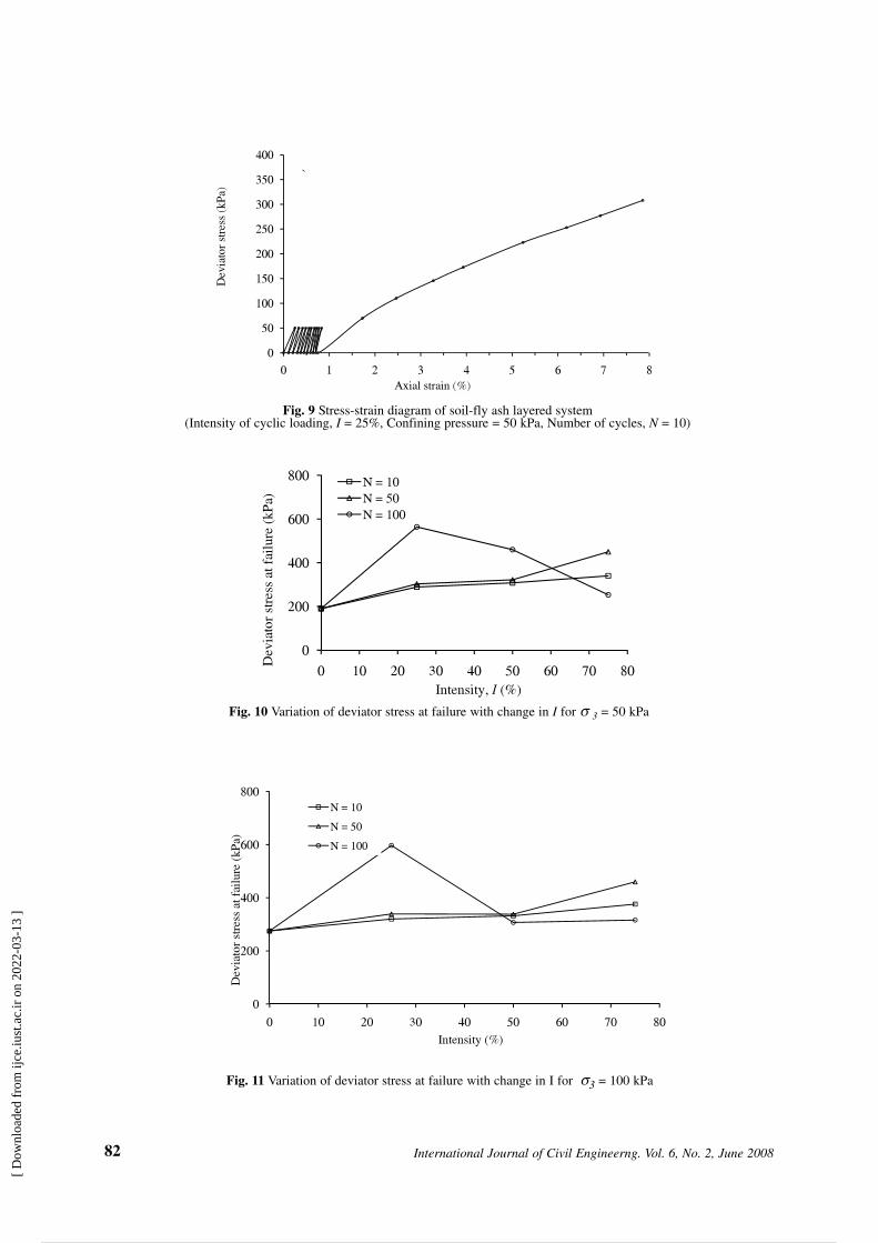
Fig. 9 Stress-strain diagram of soil-fly ash layered system(Intensity of cyclic loading, I = 25%, Confining pressure = 50 kPa, Number of cycles, N = 10)
Fig. 10 Variation of deviator stress at failure with change in I for 3 = 50 kPa
Fig. 11 Variation of deviator stress at failure with change in I for 3 = 100 kPa
[ D
ownl
oade
d fr
om ij
ce.iu
st.a
c.ir
on
2022
-03-
13 ]
10 / 17

than the corresponding value of plain soil,whereas at higher confining pressure the ultimatedeviator stress of soil-fly ash matrix is slightlymore (~3.0%) than their corresponding values ofplain soil. The failure strains of soil-fly ashmatrix are comparatively higher than thecorresponding values of plain fly ash and lowerthan plain soil. The fly ash is an inert andcohesion less material due to which it does notpossesses strength property on its own as itreduces the interlocking effect at lower strain andplain clayey soil is cohesive and fails at largerstrain due to its strength property. The soil-flyash matrix thus fails at some intermediate
strain value.
Cyclic Response
Influence of Parameters I and N
The stress-strain variation observed during theactual loading adopted in the study is shown inFig. 9. The variations of deviator stress at failureof soil-fly ash matrix with change in the intensity,I, for three different values of confining pressures( 3) are shown in Figs. 10 to 12. Each figureshows the results of three different values of N =
83Mehboob Anwer Khan, Altaf Usmani, Syed Salahuddin Shah, Husain Abbas
0
200
400
600
800
0 10 20 30 40 50 60 70 80
Dev
iato
r st
ress
at f
ailu
re (
kPa)
Intensity, I (%)
N = 10N = 50N = 100
Fig. 12 Variation of deviator stress at failure with change in I for 3 = 150 kPa
0
200
400
600
800
1000
1200
0 50 100 150 200 250
Res
illie
nt m
odul
us, M
r(k
Pa)
Cyclic deviator stress (kPa)
N=10
N=50
N=100
Fig. 13 Resilient modulus variation
[ D
ownl
oade
d fr
om ij
ce.iu
st.a
c.ir
on
2022
-03-
13 ]
11 / 17

10, 50, 100 and I = 25%, 50%, 75%. It is seenfrom these figures, that for N = 10 and 50,deviator stress at failure increases with increasein the value of I; whereas for N = 100, it increasesinitially and then decreases. It was also noticedthat the deviator stress at failure for a givennumber of cycles, N and intensity, I, increaseswith increase in confining pressure with only oneexception of N = 100 and I = 50%. It is seen fromthe figures that deviator stress at failure increaseswith increase in I for low values of N (= 10 to 50)for all confining pressures, whereas at highervalue of N (= 100), it increases up to I = 25% andthen decreases. It seems that the cyclic loadingwith low value of I acts as compactive effort thusimproving its strength, whereas, cyclic loadingwith higher value of I causes damage which getsaccumulated with increase in number of cycles.
It has been observed from the plots that for N =50 at lower values of I = 25%, there is increase indeviator stress at failure for all confiningpressures, and this increase is significant athigher values of I. At moderate I = 50%, there issome increase in deviator stress at failure for lowconfining pressures, 3 = 50 kPa, whereas there isalmost no change at higher confining pressures,
3 =100 and 150 kPa. At higher values of I =75%, there is small increase in deviator stress atfailure initially when N increases, and then it fallsdown. It has been also seen from the plots that athigher values of N = 100, there is decrease in
deviator stress at failure when intensity, I, isincreased beyond 25%. Maximum value ofdeviator load at failure was obtained for N = 100at I = 25% and under a confining pressure, 3 =150 kPa, which is approximately 20% more thanthe non-cyclic value i.e. at I = 0. Maximumdecrease in failure deviatoric stress withincreasing number of cycles is obtained forsamples tested under maximum intensity of loadI = 75% under all the three confining pressuresused for N = 100. These samples have also showncomparative increase in their permanent strainlevels as shown in Fig. 12.
It can be concluded from the above discussionthat intensity of load, I, plays an important role inthis layered combination with larger variationsobserved in failure stress at higher intensities offailure load. It is also observed that the criticallevel of intensity, I, for this layered combinationwhich represent onset of instability in terms offailure load seems to lie between I = 25% to 50%.
Resilient Modulus (Mr) and Cyclic StrengthFactor (CSF)
The resilient moduli of the samples werecalculated from the last cycle (n = N) for eachcyclic test. The plot showing variation of resilientmodulus (Mr) along with the cyclic deviatorstress level in Fig.13 clearly indicates an inverse
84 International Journal of Civil Engineerng. Vol. 6, No. 2, June 2008
0.0
1.0
2.0
3.0
4.0
0 20 40 60 80 100 120
CSF
Number.of cycles (N)
Confining pressure = 50 kPa
Confining pressure = 100 kPa
Confining pressure = 150 kPa
Fig. 14 Relation between cyclic strength factor (CSF) and N
[ D
ownl
oade
d fr
om ij
ce.iu
st.a
c.ir
on
2022
-03-
13 ]
12 / 17

85Mehboob Anwer Khan, Altaf Usmani, Syed Salahuddin Shah, Husain Abbas
0
5
10
15
20
25
30
0 50 100 150 200 250
Perm
anen
t st
rain
(%
)
Cyclic deviator stress (kPa)
I = 25 %
I = 50 %
I = 75 %
Fig. 15 Plot showing variation of permanent strain and cyclic deviator stress
y = 0.1642 x + 98.681
0
50
100
150
200
0 50 100 150 200 250 300 350 400 450
Shea
r st
reng
th, y
(kP
a)
Normal stress, x ( kPa )
I = 25 %, 50 % & 75 %
Fig. 16 Failure envelop for soil-fly ash matrix (N=10)
y = 0.1684 x + 107.99
y = 0.147x + 166
0
100
200
300
400
0 100 200 300 400 500 600 700
Shea
r st
reng
th, y
(kP
a )
Normal stress, x ( kPa )
I = 25 % & 50 %
I = 75 %
Fig. 17 Failure envelop for soil- fly ash matrix (N=50)
[ D
ownl
oade
d fr
om ij
ce.iu
st.a
c.ir
on
2022
-03-
13 ]
13 / 17

stress dependency, i.e. an increase in cyclicdeviator stress level has shown a fall in modulusvalues, with the maximum value of Mr beingobtained at I = 25% for N = 100. The modulusvalue used in the plot indicates average value ofthree confining pressures used in the study
3 = 50, 100, 150 kPa. The pattern obtainedabove is similar to as shown by Li and Selig(2001) for sub grade soils under traffic loading.The cyclic strength factor (CSF) of the layeredsamples, which is defined as the ratio of post-cyclic strength (obtained after desired number ofcycles, N) to static shear strength up to failure ofthe samples were evaluated and comparedgraphically. CSF values representing an averagevalue for three intensities, I, are plotted againstnumber of cycles, N, as shown in Fig. 14. Theplot clearly shows that the increase in strengthover static strength due to number of cycles, N, ishigher at low confining pressure of 50 kPa whileat higher confining pressure ( 3 = 100, 150 kPa)the increase is marginal. The lower increase instrength or CSF at 100 and 150 kPa of confiningpressure clearly demonstrates the prominenteffect of confinement on strength of samples, inparticular at 150 kPa pressure.
Permanent Strain Variation
Permanent strains of the sample representing
average of the three values of 3, that werecalculated relative to complete failures ofsamples were plotted against cyclic deviatorstress as shown in Fig. 14. It is observed from theplot that larger strains were obtained for samplesunder maximum intensity of load (I = 75%)showing the fact that intensity of cyclic load, I,has an exclusive role during the cyclic loading ofthe samples. These samples have also registered afall in their deviatoric stress levels with increasein number of cycles, N as shown earlier in Figs.10 - 12. On comparing the graphs of Figs. 10, 11,12 and 15, a comparative instability is observedto occur at higher intensities of load (I = 75%),with the development of higher permanent strainsand early failure of samples.
Shear Strength Parameters
The failure envelopes of soil-fly ash matrix fordifferent values of N have been plotted in Figs. 16to 18. A Mohr-Coulomb failure equation has beenproposed for different cases. The equation is ofthe type:
f = c + n tan (1)
Where,c = unit cohesion, = Angle of internal friction,
n = Normal strength and f = Shear strength.
86 International Journal of Civil Engineerng. Vol. 6, No. 2, June 2008
y = 0.1332 x + 206
y = 0.129 x + 84.077
0
100
200
300
400
0 100 200 300 400 500 600 700
Shea
r st
reng
th,y
( kP
a)
Normal stress, x ( kPa )
I = 25 %
I = 50 % & I = 75 %
Fig. 18 Failure envelop for soil-fly ash layered system (N =100)
[ D
ownl
oade
d fr
om ij
ce.iu
st.a
c.ir
on
2022
-03-
13 ]
14 / 17

There is no any significant influence of theparameter, I, for N = 10, (Fig. 15) perhapsbecause of lesser number of cycles and therefore,a common shear strength envelope have beenplotted in this figure.
The shear strength parameters of the envelopeare: c = 98.7 kPa, = 9.32o.
The shear strength envelope for I = 25% andI = 50% for N = 50, is almost the same (Fig. 16),therefore, a combined shear strength envelopehas been plotted in the figure for these two valuesof I, whereas for I = 75% a separate shearstrength envelope has been drawn. The shearstrength parameters obtained are:
c = 108.0 kPa, = 9.55° for I O 50%c = 166.0 kPa, = 8.36° for I > 50%
Two shear strength envelopes for N = 100, areconsidered, one for I = 25% and anothercombined for I = 50% and 75% whose values areclose to each other (Fig. 17). The shear strengthparameters obtained are:
c = 206.0 kPa, = 7.58° for I < 50%c = 84.0 kPa, = 7.35° for I P 50%
Conclusions
Performance based approach of pavement designusing analytical methods incorporate laboratorymeasurements of resilient modulus and resistanceto permanent deformation of the subgrade andfoundations as an important parameter ofinvestigation nowadays. This aspect of analysiswas kept in concern while drawing theconclusions from the present study. On the basisof the tests conducted in this study, the followingmain conclusions are drawn:
- Resilient Modulus values calculated fordifferent cyclic stress levels and under varyingnumber of cycles show an inverse stressdependency whereas permanent strains show alinear stress dependency. Cyclic strength factordefined for the test results appears to provide an
appropriate index for evaluating the performanceof layered system under cyclic loading.
- The development of permanent strains appearsto govern largely the stress-strain behaviour oflayered sample of soil-fly ash matrix under cyclicloading. A value of applied cyclic deviator stress(Intensity, I) above which the onset of permanentdeformation becomes unstable is shown to occurabove 50% deviator stress at failure. The cyclicloading at intensity of load, I P50% lead toinstability of soil-fly ash matrix, whereas lowerintensity of load (I = 25%) helps in improving itsshear strength characteristics. The experimentalinvestigation substantiates the use of fly ash inlayered combination with clayey type of soilunder lower number of cycles with high value ofintensity of load ( I ) and for higher number ofcycles with lower value of parameter, I.
- The study shows that the value of deviator stressat failure and cohesion continuously increaseswith the increase in the number of cycles, N forlower values of I (I O 25%) in soil-fly ash matrixunder cyclic loading conditions that signifies thegood performance of this combination underlower percentages of failure stress levels. Atlower intensity of load and higher number ofcycles, the strength of layered system of soil-flyash matrix increases due to interlocking of fly ashparticles and binding effect of interfaces of soiland fly ash layers. Further studies need to be doneon such layered arrangement employing fly ashas one of the constituent material for its massscale utilization to explicitly understand itsresponse under varying cyclic loading conditions.
- The Mohr-Coulomb equation derived form theexperimental data looks to provide reasonablefirst order accuracy. The results form the studiescould be utilized in the development of anadvanced constitutive model based on theory ofelasto-plasticity.
- Furthermore as being a totally new area ofresearch, the results form this study can be usedas a preliminary basis for advanced levelresearches.
87Mehboob Anwer Khan, Altaf Usmani, Syed Salahuddin Shah, Husain Abbas
[ D
ownl
oade
d fr
om ij
ce.iu
st.a
c.ir
on
2022
-03-
13 ]
15 / 17

- Clay and fly ash, which are usually, consideredundesirable materials for embankmentapplications when used independently have beenconverted into useful materials by their layeredcombination.
References
AASTHO (1982), “Standard method oftest for resilient modulus of sub gradesoils”, Designation T274-82, Am. Assn. ofState Hwy. and Trasp. Officials,Washington, D.C.
Brown, S.F and Hyde, A.F.L. (1975),“Significance of cyclic confining stress inrepeated-load triaxial testing of granularmaterial”, HRR 537, HRB, WashingtonD.C., 49-58.
Brown, S.F., Lashine, A.K.F. and Hyde,A.F.L. (1975), “Repeated load triaxialtesting of silty clay”, Journal ofGeotechnical Engineering Division,ASCE, 25(GT1), 95-114.
Castro, G. and Christian, J.T. (1976),“Shear strength of soils and cyclicloading”, Journal of GeotechnicalEngineering Division, ASCE. 102(GT9),887-894.
Cocka, E. (2001), “Use of class C fly ashesfor the stabilization of expansive soil”,Journal of Geotechnical andGeoenvironmental Engineering, ASCE.Vol. 127, No.7, 568-573.
Consoli, N. C., Prietto, P.D.M., Carraro,J.A.H. and Heineck, K.S. (2001),“Behaviour of compacted soil-fly ashcarbide lime mixtures”, Journal ofGeotechnical and GeoenvironmentalEngineering, ASCE. Vol. 127, No.9, 774-782.
Diyaljee, V.A., and Raymond, G.P. (1982),“Repetitive load deformation ofcohesionless soil”, Journal of theGeotechnical Engineering Division,ASCE. Vol. 108(GT10), 1215-1229.
Hyodo, M., Yashura, K. and Murata, H.(1996), “Deformation analysis of soft-clayfoundation of low embankment road under
traffic loading”, Proc., 31st Symposium ofJapanese Society of Soil Mechanics andFoundation Engineering, Japan, 27-32.
Li, D. and Selig, E. T. (2001), “Cumulativeplastic deformation for fine-grainedsubgrade soils”, Journal of GeotechnicalEngineering, 122(12), 1006-1013.
Matthew, W., Frost, Fleming, R. Paul andRogers, C.D.F. (2004), “Cyclic triaxialtests on clay subgrades from analyticalpavement design”, Journal of theTransportation Engineering Division,ASCE. Vol. 130, No.3, 378-386.
Phani, B.R. and Radhey S. Sharma (2004),“Effect of fly ash on engineeringproperties of expansive soil”, Journal ofGeotechnical and GeoenvironmentalEngineering, ASCE. Vol.130, No.7,764-767.
Pumphery, Jr., N.D. and Lentz, R.W.(1986), “Deformation analysis of FloridaHighway subgrade sand subjected torepeated load triaxial tests”, TRR 1089,TRB, Washington D.C., 49-56.
Seed, H.B. and Chan, C.K. (1958),“Effects of stress history and frequency ofstress application on deformation of claysub grades under repeated loading”, HRBProceedings, No. 37, 555-575.
Seed, H.B., Chan, C.K. and Monismith,C.L. (1995), “Effects of repeated loadingon strength and deformation of compactedclay”, HRB Proceedings, No. 34, 541-558.
Seed, H.B. and McNeill, R.L. (1956), “Soildeformation in normal compression andrepeated loading test”, HRB Bulletin 141.Seed, H.B., McNeill, R.L. and Guenin,J.de (1960), “Clay strength increase causedby repeated loading”, ASCE Transactions,Paper No. 3018, Vol. 125. 141-161.
Sharma S.S. and Fahey, M. (2003),“Evaluation of cyclic shear strength of twoconcentrated calcarious soil”, Journal ofGeotechnical and GeoenvironmentalEngineering, ASCE. Vol. 127, No.9,774-782.
Shroff, A.V. and Shah, M. (2004), “Soil-Fly ash interaction technique for stability
88 International Journal of Civil Engineerng. Vol. 6, No. 2, June 2008
[1]
[2]
[3]
[4]
[5]
[6]
[7]
[8]
[9]
[10]
[11]
[12]
[13]
[14]
[15]
[16]
[17]
[ D
ownl
oade
d fr
om ij
ce.iu
st.a
c.ir
on
2022
-03-
13 ]
16 / 17

analysis of existing bridge approaches”,ICGGE Proceedings, IIT, Bombay, India,pp. 243-246.
Thiers, G.R. and Seed, H.B. (1969),
“Strength and stress-strain characteristicsof clays subjected to seismic loadingconditions”, ASTM, 450-456.
89Mehboob Anwer Khan, Altaf Usmani, Syed Salahuddin Shah, Husain Abbas
[18]
[ D
ownl
oade
d fr
om ij
ce.iu
st.a
c.ir
on
2022
-03-
13 ]
Powered by TCPDF (www.tcpdf.org)
17 / 17