a study of cathode drift compensation in d-c amplifiers
TRANSCRIPT

Scholars' Mine Scholars' Mine
Masters Theses Student Theses and Dissertations
1949
A study of cathode drift compensation in D-C amplifiers A study of cathode drift compensation in D-C amplifiers
Joseph W. Rittenhouse
Follow this and additional works at: https://scholarsmine.mst.edu/masters_theses
Part of the Electrical and Computer Engineering Commons
Department: Department:
Recommended Citation Recommended Citation Rittenhouse, Joseph W., "A study of cathode drift compensation in D-C amplifiers" (1949). Masters Theses. 4892. https://scholarsmine.mst.edu/masters_theses/4892
This thesis is brought to you by Scholars' Mine, a service of the Missouri S&T Library and Learning Resources. This work is protected by U. S. Copyright Law. Unauthorized use including reproduction for redistribution requires the permission of the copyright holder. For more information, please contact [email protected].

A STUDY OF CATHODE DRIFT
COMPENSATION IN D-C AMPLIFIERS
BY
JOSEPH W. RITTENHOUSE
A
THESIS
submitted to the faculty of the
SCHOOL OF MINES AND METALLURGY OF THE UNIVERSITY OF MISSOURI
in partial fulfillment of the work required for the
Degree of
MASTER OF SCIENCE IN ELECTRICAL ENGINEERING
Rolla., Missouri
1949

1i
ACKNOWLEDGMENT
The author desires to express his sincere appreciation
for the invaluable advice and recommendations given to him
by Professor Carl Johnk during the course of this work.

iii
CONTENTS
Page
Acknol..,ledgment. " It • • • • • • • • • • • • • • • • • • 11
List of Illustrations •.•.•.•.••......................•.• iv
List of Tables.......................................... v
Introduction. . . . . . . . . . . . . . . . . . . . . . . . . . . . . . . . . . . . . . . . . . . . 1
Review of L1 ter tLlre.................................... 4
A-C Equivalent Circu~t Analysis of the Miller Circuit •.. 10
Graphical Analysis Of The Miller Circuit Containinga Large Load Resistor •.....•..••.....•••.•.•••.••••.. 15
Gr phic~l Analysis Of The Miller Circuit Containinga Small L02d Resistance ....•.•.•...........•..••...•. 20
Experimental Work On The Miller Circuit •...••....•...•.• 25
Additional Mathematical Analyses of the Miller Circuit .• 30
Mathematical Analysis of a Single Triode Circuit •.•.•.•• 37
A Proposed New Circuit •....••.•.•.•.•.•.•••.•.•.•.•••••. 40
Mathematical Analysis Of The Proposed Circuit •...•.•.•.• 43
Graphical Analysis of the Proposed Circuit •...•.•.•.•... 47
Some Seeming Limitations of the Proposed Circuit •...•..• 52
Experimental Work On The Proposed Circuit•....••.....•.. 54
Summary and Conclusions................................. 59
Appendix A. . . . . . . . . . • . . . . . . . . . . . . . . . . . . . . . . . . . . . . . . . . . . . 61
Appendi x B.......... . . . . . . . . . . . . . . . . . . . . . . . . . . . . . . . . . . . . 64
Appendix C.............................................. 67
Bibliography. . . . . . . . . . . . . . . . . . . . . . . . . .. . . . . . . . . . . . . . . . . ... 70
Vi t ?l

iv
LIST OF ILLUSTRATIONS
Figure
1 The Miller Circuit Showing The EquivalentCathode Drift Noise Voltage Generator, en..•..
Page
5
2 A-C E uivalent Circuit for Miller Circuit 11
3 Graphical Constructions For The Miller CircuitHaving A Large Load Resistor ..............•... 17
4 Graphical Constructions For The Miller CircuitHaving A Small Loa~ Resistor ...........•..•... 21
5 The Test Circuit Used With The Miller Circuit ••.• 26
6 Drift Curves For The Miller Circuit ....•....••.•• 28
7 A-C Equivalent Circuit For The Miller CircuitAssuming Different Noise Voltages •...•.•••...• 32
8 Conventional Triode Amplifier •.•••.•.•.....•.•.•. 38
9 A-C Equivalent Circuit For A ConventionalTriode Amplifier.............................. 38
10 The Proposed Circuit Showing The EquivalentCathode Drift Noise Voltage Generator, en.•••. 41
11 A-C E uivalent Circuit For The Proposed Circuit .. 44
12 Graphical Oonstructions For The ProposedCirouit Using A 68L7 Tube •.•......••••.•.••.•• 48
13 The Test Circuit Used With The Proposed Circuit.. 55
14 Drift Curves For The Proposed CircuitUsing A. 6sL7 Tube............................. 56
15 Drift Curves For The Proposed CircuitUsing A 6J'6 Tube.............................. 58
16 Graphical Constructions For The ProposedCireui t Using A 6J6 Tube.......... . . . . . . . . . . .. 65

v
LIST OF TABLES
Table Page
I Drift Data For iller Circuit HavingA 106 ohm Load Resistor. . • . • . •. . . .. •.• . .. • . . . 61
II Drift Data For Miller Circuit HavingA 40K Ohm Load Resistor............ ....•.. . .. 62
III Drift Data For Conventional TriodeAmplifier Using a 6SL7 Tube •.........•....... 63
IV Drift Data For The Proposed CircuitUsing A 6SL7 Tube ..•.....•••.•...••..•....... 67
V Drift Data For The Proposed CircuitUsing A 6J6 Tube.... . . . . . . . . • • . . . . • . . . . . • . • . . 68
VI Drift Data For A Conventional TriodeAmplifier Using A 6J6 Tube ....•.••• ~ ..•••••.• 69

1
A Study of Cathode Drift Compensation inD-C Amplifiers.
I. Introduction
The expression, cathode drift, has to do with the ran
dom variations in vacuum tube plate current which are
attributable to similar v riatione in emission velocities
of electrons leaving hot cathodes. The fact that t ese
random current changes appear to result from spurious drifts
in cathode potential, since all other electrode potentials
are unrelated to them, give rise to the expression, cathode
drift.
The exact nature of the cause of cathode drift is not
known in great detail. It is known, however, that faotors
contributing to the phenomenon are: variations in work
function of the cathode (which are partially attributable to
inability to produce absolutely pure oathode materials) and
random fLuotu tions in cathode temperature (Which may be
oaused by suoh things as unstable heater voltage, random
changes in ambient temperature, and non-uniform flow ot
cooling g saes over the cathode).
It is significant, in this respeot, that the effects of
oathode drift are exaotly as though some random noise-volt
age generator were located in the cathode lead of the vaouum
tube in question. Such a generator would introduoe random
changes in cathode-to-grid potential differenoe which would
exactly account for the variations in plate current which

are the only evidenoes of cathode drift.
The difficulties which arise trom cathode drift are
largely associated with the application of thermionic tubes
to direct-coupled amplifier problems. For example: a tri
ode operating as a voltage amplifier in the input stage of
a direot-coupled amplifier is unable to distinguish between
those changes in plate current which stem from changes in
input signal and those which arise from the cathode-drift
effect; consequently, both sources of plate current change
will produce a change in output voltage.
Since, in a d-c amplifier, the coupling betleen stages
is a conductive coupling, the relatively long-tiMe-varying
output voltage changes which were initiated in one stage by
cathode drift appear to the next stage as an integral part
of the amplified signal voltage.
The unique association of this problem with direct
coupled amplifiers, of course, is a result of the fact that
the oathode-drift plate current changes invariably are com
posed of such low-frequenoy components that their passage
through the ooupling networks of any ot the non-direct
coupled amplifiers is inhibited so that they hardly ap ear
in the output signal at all.
The problem with which this paper is concerned is a
stUdy of some of the possibilities of oompensating for
cathode drift etfects in a single amplifier stage. Specif
ically, this paper will:
2

3
(A) present a detailed mathema~ical and graphi
cal analysis of the so-oalled Miller(l) cir-
(1) Miller, S. E., Sensitive D-C Amplifier With A-C Operation, Eleotronios, Vol. 14, Page 27, November, 1941.
cuit and using this analysis, together with
experimental evidence, will remove some of
the limitations which the originator of this
circuit initially assooiated with it; and
(E) propose a new dual triode cirCUit, haVing
only one resistor at the low voltage level,
which will compensate for cathode drift
while operating from a single B voltage
supply.

II. Review of Literature
It wou~d appear that the simplest possible solution to
the problem of cathode drift might be simply to eliminate
its original cause. A review of the literature, however,
will reveal that removal of the cause is hardly an econom
ical approach to the solution, since such an approach would
require one to develop sources of absolutely fixed voltages
for filament supplies, and to produce cathode materials
whose work functions are absolutely fixed in magnitude.
A more reasonable approach, then, would seem to be one
which seeks to nullify the normal effect of cathode dritt
rather than to eliminate the drift itself. This is the
approach taken by Miller(2) in his development of the
(2) Miller, S. E., A Stable, Sensitive D-C Amplifier UsingA-C Power Exclusively, Thesis, Massachusetts Instituteof Technology, Cambridge, Mass.
circuit which bears his name.
Tbis cirouit, shown in Figure 1, consists of a dual
triode, one section ot whioh is oonneoted as a conventional
amplifier, wbile the other section behaves as a cathode
follower with self bias which, through the effect of its
plate current in the cathode resistors R1 and Rz, produces
the change 1n voltage at the amplifier cathode which is
just necessary to prevent the change in amplifier plate
current, il, hich would normally accompany a given change
in e~ectron emission velocity.
4

2
!be 11ler 01rou1t, 8hoV1n1 nt 0 thod 501•• Tolt e ne .to , •
'1 • 1

. . • (1)
6
The voltage, en, shown in series ,nth the oathodes of
the tubes in Figure 1 is a fictitious voltage whose random
variations are assumed to be responsible for the random
changes in plate current that are caused by cathode drift.
The notation of Figure 1 will be employed throughout
the discussion of the Miller circuit.
The mechanism by which compensation is aocomplished in
this circuit does not lend itself to simple qualitative
explanation, yet it has been shown both mathematically and
experimentally that compensation is effected. (3)(4)
( 3 ) 112.1:£•
(4) Valley, G. E., Jr., and allman, H., Vacuum-TubeAmplifiers. N. Y., McGraw Hill, 1948. pp. 462-463.
In his original paper, Mr. Miller did not inclUde all
the steps involved in his mathematioal treatment of this
circuit; however, on the basis of what he did present, the
following analysis has been developed and it is believed
to be very nearly identioal to that whioh was prepared by
Miller.
By referring to Figure 1, the following e uations can
be written if RL is assumed to be large enough to make i l
large compared to i2:
i2 = p.2(en - R.li2) + enRl + R2 + rZ

• . • (3)
7
e = en - (RI + R2)i2 (2)
Solvin for en from Equation (2) nd substituting for en in
Equation (1):
i2
= ~2[e + iZ(Rl + HZ) - Rli2] + e + 12{Hl + Rz)RI + R2 + rZ
where:
~2 = Amplif1oation factor of T2
12 = Plate current of T2
r2 = Plate resistanoe of TZ
Expanding and simplifying:
12Rl + i2Hz + i2r 2 = Jl2e + iZ~RI + i21J.Z!1z - f.lzizRI
+ e + 1ZRI + izHze(~ + 1) = iZ(rZ - J..L2R2)
e = i2(rz - ~2R2)\-LZ + I
From Equation (2)
i • en - e2 . RI + RZ
Substituting in (3)
e = (~n - e)(r2 - \-L2R2)(J.L2 + 1) (R1 + ~)
= enr2 - \-LgR2en - erg + \-LZeRg\-L2R1 + \-L2R2 + RI + Hz
expanding and simplifying:
e = en(rg - \-LgR2)(1-12 + 1) Rl + Rz + r2
. . • (4)

8
Now, Miller re sons, if e becomes equal to zero, then
the random v riations in en will have been compensated; so
if the right hand side of Equation (4) is equated to zero
there is obtained the criterion:
R2 = .:z. • .2-J..L2 gm2
where gm2 = the transconduct ce of T2
From this work stems the conclusion that the circuit
of Figure 1 will compensate for cathode drift effects pro
vided that RL is made very large and provided that ~ =.lgm2
It will be observed that the assumption that RL is
large is a r ther arbitrary one, the reason for blch
seems to be solely to simplify the writing of Equations
(1) and (2) by permitting volt ge drops to be written in
terms of i2 alone instead of in terms of the more exact
expression, (11 + 12 ).
While it is true that such an assumption does facil
itate the writing of the initial equations, it is equally
true that it limits the applicability ot the Miller cir-
cult to problems in which frequency response is of secon
dary importance to gain requirements. This rather serious
llmitation, together with certain seeming errors in
another author'g(5) discusslon of the Miller circuit,
(5) Yu, Y. P., Cathode Follower Coupling in D-C Amplifiers,Electronics, Vol. 19, Page 99, August, 1946.

led the author into a preliminary investigation which
seemed to corroborate his original suspicion that the
foregoing limitation was an unnecessary one.
This same preliminary investigation revealed the addi
tional possibility that there could be developed a new com
pensating circuit involving two triodes which would have a
twofold advantage over the Miller circuit in that it could
operate from a single regulated B+ supply, and it would
have one less resistance at its low voltage level than does
the Miller circuit.
It should be pointed out that the elimination of one
resistance at a low voltage level becomes exceedingly im
portant 1n those applications in which the noise voltages
generated in the resistance are of the same approximate
order of magnitude as are the signal voltages to be ampli
fied.
9

10
III. A-C Equivalent Cirouit Analysisof The Miller Cirouit.
It will be reoalled from Figure 1 and previous disous
sion that other workers (6) (7) (8) have oonsidered it eatis-
(6) Miller, s. ... .Q.l2.. Cit •~. ,
(7) Yu, Y. P. , .Ql2.. Cit.
(S) Valley & Wallman, .Ql2.. Cit •
faotory to represent cathode drift as a random noise-voltage
generator located in the oathode of the tube under oonsid
eration. In fact, Miller's analysis presumes that the
noise voltages associated with the cathode drift of the two
seotions of a dual triode are identioal if the two sections
have a common cathode.
The fact that Miller's presumption is largely justifi
able is evidenced by the high degree of compensation whioh
his experiments revealed were possible; oonsequently, for
the purposes of this portion of this paper it was assumed
that the cathode drift effect oan be represented in the
Miller Circuit by a single random noise-voltage generator
located in the common oathode lead of the dual triode.
Making this assumption the A-C equivalent oircuit
associated with the oirouit of Figure 1, when the grin of
T1 is grounded, is shown in Figure Z where:
rl • the plate resistanoe of TI
r2 =' R n n TZ

1•f"\,J --~V\JV\Jf\--"""J\I~-----1
A-G qui..l. t 01rou1t t JlU1 r 1ro
r1. 2
11

12
~l • the amplification factor of ~l
JJ.z::lll II " •• T2
From an analysis of Figure 1, taking into considera
tion proper phase relationships, it can be seen that with
the grid of Tl grounded:
. . • (5)
and
( 6)
Using Equation (5) and applying Kirchhoff's law of
Bummation of voltages around the top loop of Figure 2, the
following expression waS obtained:
~l[(il + i 2 )(Rl + ~) - en] = en-(11 + l2)(~ + Rz)- i 1 (R3 + r 1 )
Rearranging:
il[(~l + l)(Rl + R2) + R3 + rl] + i2(~1 + l)(Rl + Rz)
= (~l + l)sn • . . (7)
Now, using Equation (6) in a similar summation around
the bottom loop of Figure 2, the following results were
achieved:
~[(11 + i 2 ) R1 - en] • en-(il + l Z)(Rl + Rz) - i 2r Z
Rearranging:
i1[(~2 + 1) R1 + Rz] + l2[(~Z + 1) ~ + Rz + r 2]
a (~2 + 1) en • (8)

13
Solving Equations (7) and (8) for i l by determinants:
(1-L1 + 1) en (1-L1 + 1) (R1 + Rz)(J.12 + 1) en [(1-L2 + 1) R1 + ~~ + rZ]i
1= _--=- ~;:-_....::::'--:-_.....:=:.__-~-G_~...:._
Denominator
[(I-LJ. + 1)[ (~ + 1) ~ + Rz + r Z]
= - -::(=-I-L...l_+-;--l_)(:--1-L""",2_+_l _)_(~ +_Rz~)):--t4enDenominator
Since the ~enominator obviously consists of constants only:
~ = (1-L1 + 1)[(1-L2 + 1) R1 + R2 + r2Jden K
_ (1-£2 + 1) (Rl + R2 )(1J,1 + 1)K . . • (9)
Since ~il 0 is the condition for which this circuitden
was originally developed, it was proposed to equate the
right hand side of Equation (9) to zero and solve for the
conditions under which this equality would exist.
Let
o
Then from Equ tion (9)
(I-Ll + 1)[(1-L2 + 1) Rl + ~ + r2]K
o
But
(J.L2 + 1) (Rl + R2)(1-L1 + 1)- K
(I-Ll + 1) cannot equal zero and the denominator must be
finite, nd greater than zero, so:
(J.L2 + 1) R1 + R2 + r2 - (1-L2 + 1)(R1 + R2 ) = 0

14
Simplifying:
• • • (10)
Where gm2 is the transconductance of T2 ,
The significant aspect of this treatment is that it
introduces no assumption whatsoever regarding the relative
magnitudes of the various resistances in the circuit, yet
the criterion for ~ = 0 which it yields is identical tooen
criterion which Miller obtained from a derivation based on
the assumption that RL is so large that the plate ourrent
of Tl is negLigible oompared with the plate ourrent of T2 •
This would seem to indicate that the requirement ot
a large RL in this circuit is an unwarranted one. It was
felt, however, that a mere mathematioal treatment waS in
conclusive in firmly SUbstantiating this contention; so a
program of experimentation waS initiated in an effort
to oonfirm the foregoing indioations that the iller oir
ouit will oompensate for oathode drift even though RL may
be small.

l5
. IV. Graphical Analysis of the Miller CircuitContaining a Large Load Resistor
In order to oompare the extent to which the Miller
circuit would compensate for oathode drift effects when
both large and small load resistances were used in the
amplifier section, it was first necessary to determine the
values of the various cirouit elements to be employed in
the oircuit; consequently, the following graphical analy
sis was proposed as a basis for the selection of oirouit
components in the case in hich a large load resistance is
used. This analysis is for a circuit containing a 6SL7
dual triode.
On the oharacteristic ourves or the 6SL7 in Fi ure 3
was dra~m a load line, AB, to represent the l-megohm load
which was selected for the case in which RL is large. From
this construction, it can be seen that a 255-volt supply
was selected for the amplifier tube.
Atter having drawn this load line, a reasonable oper
ating point was assumed as is indicated by point C in Fig
ure 3. This oper ting point established the bias on Tl as
-2 volts and the static plate current of Tl as 0.125 mil
liampere~.
Having established an operating point for Tl' values
for (RI + RZ) and i 2 were assumed such that the product of
the assumed (Rl + RZ) and (il + i2) ould yield the desired
bias of -2 volts on TI.

16
Since the assumed value of (Rl + R2) is the only load
on T2 , a load line could be dra~m on Fi ure 3 for T2• In
this case (Rl + R2) was found to be 1778 ohms when i2 was
assumed to be 1 milliampere; so line DE in Figure 3 repre
sents a l778-ohm load line when a plate supply voltage of
105 volts is used with T2"
On this 1 tter load line, DE, the assumed plate cur
rent of 1 milliampere was found to exist at a grid bias of
-0.61 volts a8 indicated by point F in Figure 3; so at this
operating point the reciprocal of the transconductance of
T2 was calculated by gra hlcally taking the reciprocal of
the slope of the plate current vs. plate voltage curve and
dividing this reciprocal slope by the amplification factor,
~, of the tube.
Reference to Figure 3 will reveal that the reciprocal
slope of the curve in question is equal to ~Ep which in~i2
this instance is 47.7 x 10³ ohms, and since ~ for a 6SL7
equals 70, the reciprocal of gm2 in this c se will equal47.7 x 103
70 or 680 ohms.
It will be recalled from E
value which must be used for ~
uation (10) that this is
in order that ail shall~en
equal zero; so immediately, since Rl + ~ =1778 ohms,
RI can be found to be 1098 ohms.
At this point it was necessary to determine whether
this value for Rl multiplied by the sum (il + i2)'
the

2
A
o~~==~=f=]~r=~=::;:~~~~~-2.L50!B---,alt,
Gr ph10 . don8truotlon For Miller CirouitRavin A Large Load R lstor
J'lgure 3
1'1

18
~.125 x 103 amperes, would yield the previously determined
value of -0.61 volts as a bias on T2 . Actually the product
of (il + i 2 ) ~ = 1.235 volts; conseauently, some of the
previously used values haa to be edjustea by trial end
error processes until 8. set of v81ues v,J88 found which would
produce the assumed operpting conditions for both tubes.
Examination of Figure 3 will reveal that 8 relatively
large ch8nge in Rr will produce very little effect on the
slope of the lO~d line of T2
• Furthermore, no change in
Rl COuld prOduce p change in i l of more than about +0.130
milliamperes; so it seemed logical to try changing R1
in
n effort to achieve more nearly the origin 11y assumed
operating conditions.
If a v lue of ~ = 542 ohms V,ere used, the sum
(Rl + R2 ) WOUld equal (680 + 542) = 1222 0~~8. As has been
observed, a l222-ohm load line on Figure 3 in place of the
existing l778-ohm line WOUld haTaly introduce a perceptible
difference; so the l778-ohm line waB retained.
Still assuming 12 = 1 milliampere, and considering the
change in i lto be negligible so far as its effect on biaB
values is concerned, the ne1 bias on Tl i as round to equal
approximately 1.125 x 1222 x 10-3 = 1.375 volts and the bias on
TQ w s calculated as: 1.125 x b42 x 10-3 = .61 volts •......
These values suitably agreed with the originally
assumed values, and since the operAting point of T0 was(..-

19
still the same as it was when im2 was originally caloUlated,
it could be expected that when the folloldng values, as
determined above, were employed in the Miller circuit
(Figure 1), compensation for cathode drift could be antici
pated:
~= 542 ohms
R2 = 680 ohms
R3 = 106 ohms
Ebbl = 255 volts
Ebb2 = 105 volts
It is significant in this analysis that the smallness
of il as com ared to i 2 did permit some simplification in
the graphioal procedures just as it did in Miller's mathe
matical analysis; the work of the following section, how
ever, will reveal that this smallness of il is not a neces
sary condition to suooessful operation of the oircuit.

20
v. Gr phical Analysis of the illerCircuit Containing a Small Load
Resistance
The procedure for selecting circuit parameters when ~
is small was similar to the foregoing graphical analysis in
that it resolved into a series of solutions based on assumed
values, each of which solutions contained certain correc-
tions for errors which became apparent in the next preceding
solution.
In this specific case, a 68L7 tube was used with a
value of RL = 40,OOO-ohms; so, as in the preceding case, a
load line for a 40,OOO-ohm resistance was drawn on the tube
characteristic curves, as shown by line AB, in Figure 4. A
B+ supply of 255-volts was used.
A value of bias voltage on Tl equal to -2.25 volts was
aseumed, thereby establishing the operating point as shown
at C in Figure 4. The static value of i l was established as
1.1 milliamperes.
For TZ a value of plate-supply voltage equal to 105
volts and a plate current of 1 milliampere were assumed.
As was true in the previous analysis, the Bum of this
plate current plus the plate current of Tl was used to de
termine the required value of (Rl + R2) by observing that
Rl + R2 = Eeli 1 + i2
where Eel is the bias on TIe

2
B
Do --"""",--~=-----L---:1"""'O"""-""""'--L-_"""",-_--&.._---&_-"""-
l~ 200Plate Volt.
Grapb10 1 Con.truot1on tor the H1ller 01rou1tHaTing a B 1 Load Reel tor
r1gur "

22
In this case,
R R 2.251 + 2 = 2.1 x 10-3
= 1070 ohms
Using the value of 1070 ohms as the load on T2 a load
line, DE, was drawn through Ebb2 = 105 V on the tube char
acteristic curves as shown in Figure 4. On this load line
at point F it was found that the assumed plate current of 1
milliampere occurred at a grid bias, Ec2 ' of about -0.61
volts again. In other words, the operating point of T2 in
this case was very little different from the operating point
in the case involving a large load resistance. This of1course meant that gm2 and consequently R2 would still be
680 ohms, and since Rl + R2 =1070 ohms, Rl became 1070
680 • 390 ohms.
Having found this value for R1 it was necessary to
caloulate a value for Ec2 to determine whether the aotual
value would equal the previously assumed value of -0.61
volts. Therefore:
Ec2 = (il + 12 ) R1
= (1.1 + 1) x 10-3 x 390
-= .82 volts
This value i8 obviously larger than the assumed value;
so it was a.eo'ided to try a new value of bias, Eel' on TI .
The value of -2.1 volts waS used and ae is indicated at
point G in Figure 4 this new operating point yielded a new
il of 1.2 milliamperes.

23
This change in il required a new calculation of
(Rl + R2 ):
Rl + Rz = ~fJ.
~ 2.2 ;·to 3 = 955 ohms
Theoretically this new value of (Rl + Rz) would have
necessitated the construction of a new load line for T2 , but
practically there would have been a negligible difference
between the 1070 ohm line previously constructed and the
new 955 ohm line; so the former line was retained.
Since the operating point, F in Figure 4, of T2 was not
changed, gl and consequently Rz remained at 680 ohms; som2
the new value of Rl was calculated as follows:
Rl = 955 - 680
• 275 ohms
Usin this value of Rl the actual value of bias, Ec2 '
on T2 was again calculated:
Ec2 = (i1 + i 2 ) Rl
= (1.2 + 1) x 10-3 x 275
• .605 volts
It was concluded that this value of Ec2 was sufficient
ly close to the originally assumed value of 0.61 volts to
justify the use of the following circuit constants taken
from the foregoing analysis:
Rl = 275 ohms
R2 = 680 ohms

RL = 40,000 ohm.s
Ebb1 = 255 volts
Ebb2 = 105 volts
It will be observed that in this treatment it was not
necessary to assume any predetermined relationship between
the relative magnitudes of i l and i 2"
24

25
VI. Expe imental fork on the iller Circuit
The preceding mathematical analysis demonstrates the
existence of a criterion for cathoae-drift compensation by
the Miller circuit without regard for the relative magnitude
of the load resistance in the amplifier section of the cir-
cuit.
The foregoing graphical rolalyses demonstra~e that it
is possible to select circuit constants such that reasonable
operating points can be achieved for both tubes of the cir
cuit and at the same time the required condition for con
trol, R2 • -l- can be established regardless of hathergm2'the load resistance for Tl is large or small.
It would seem reasonable, then, to test the effect upon
compensation of varying RL from the large value considered,
106 ohms, to the small value considered, 40,000 ohms. To
this eud. the following program of experimentation waS pur-
sued.:
The circuit of Figure 5 was constructed using the
follOWing eqUipment:
oltage Divider consisting of Sh lcross #441& 442 Dec de nits.
Galvanometer
Standard Cell
Potentiometer
B Battery
Heater Battery
Leeds & Northrup, Type 2500
Eppely Cat. #100
Leeds & orthru, Type K-220.1 megohm
.1 megohm
Burgess #2308 Batteries
Edison Cells

t---..-.o +Po ft'1
ter
!o Heater.
!he !e t Cirouit Use4 W1th the Killer Otrault
r1gure e

27
Heater Supply Voltmeter Weston MOdel 45
RI Carbon Resistor
R2 Carbon Resistor
RL Carbon Resistor
In Run #1, with v~lue8 of Rl , Rz, and RL corresponding
to those found in Section IV (which treats the case involv
ing a large load resistance), heater voltage was varied, to
simulate cathode drift, over a range of 10% below and 10%
above some reference value near rated voltage. For each
value of heater voltage the voltage at the plate of the
amplifier tube was measured by means of the potentiometer
and voltage divider. This data is contained in Appendix A.
Curve #1 in Figure 6 represents the manner in which
output voltage varied with respect to heater voltage; con
sequently it is indicative of the extent to which the
simulated cathode drift effects were reflected in the out-
put of the stage.
In Run #2, with values of Rl' R2, and RL corresponding
to those found in Section V (which treats the c se involv
ing a small load resistance), a set of data similar to that
described above was taken and is included in Appendix A.
Curve #2 in Figure 6 represents the manner in which
output voltage varied with heater voltage in this case.
In Run #3, with the plate, grid, cathode, aHa heater
of T2 disconnected from the rest of the circuit and
grounded, RL was again adjusted to 106 ohms while (RI + R2)

+5
ll:l /#1p..... +10t> 0- ---0-~ 0 n-- .~ _-:::...=.. ::.-.::::50.,
.j-)
:3 -1It)I~ -2I~
-3~G)()
H -4Q.)
-~10-oJ
- +10e
Dr tt Curv 8 tor the Miller Oirouit
Figure 6
8

29
was adjusted to proauce the same 1 te current in T1 as had
existed in Run #1. With these adjustments the oirouit
simply beoame a single triode amplifier stage lith no com
pensation for cathode drift.
After the above adjustments had been made a third set
of heater voltage versus output voltage data (see Appendix
A) was taken and plotted as Curve #3 in Figure 6. This
curve represents the extent to which the simulated cathode
drift effect is reflected in the output of a completelr
uncompensated triode amplifier circuit. It is significant
also that thi cu ve agrees closely with the accepted
general values(9) of output voltage drift over a 20% change
(9) Valley & Wallman, ~. Cit., pp. 458-459.
in heater voltage in an uncompensated triode amplifier
stage.
It is believed that a visual comparison of the slopes
of Curves I and 2'with the slope of Curve 3 is sufficient to
indicate that the Miller circuit is indeed uite effective
in compensating for cathode drift effects.
It is further believed that the curves of Figure 6
leave little question as to the ability of this circuit to
affect such compensation whether the load resistance be
large or small.

30
VII. Additional Mathematical Analysesof The Miller Circuit
In studying the Miller circuit the author came to re
gard its two required B+ voltages as a distinct disa van
tage, in that a regulated power supply to provide these two
voltages is inherently more bUlky and more expensive than
would be a similarly regulated supply to provide only one
B+ voltage. (A bit of reflection will reveal that B+ sup
plies intended for use with highly stable D-C amplifiers
must always be very well regulated lest a random-varying B
voltage introduce the same sort of spurious plate current
changes as re caused by cathode drift.)
Furthermore, it as believed that the use of two re
sistors in the common cathode lead of the tlO tubes s
objectionable in that such use introduces two possible
sources of resistance-noise-voltage at a low voltage level
in the circuit; consequently, it was proposed to explore at
greater length the possibilities of additional mathem tical
treatment of the circuit of Figure 1 with the hope that
such exploration might produce a clue to an improved control
circuit.
It will be recalled that throughout all the previous
discussion it has been assumed that a single noise voltage
generator, indicated s en in Figure 1, coula adequatelyI
represent the cathode drift effects of both TI and TZ in the
Miller circuit. Actually, however, it 1s highly improbable

31
that the random effective changes in potential of the
cathode of Tl are exactly equal to such changes in T2; in
fact, it is quite probable that the differences in cathode
arifts of Tl and T2 are at least partly responsible for the
deviation of Curves 1 and 2 of Figure 6 from straight hori
zontal lines.
Recognizing that the elimination of this inconsistency
might yield a clue to a new cathode-control circuit, the
revision shown in Figure 7 was made in the A-C equiValent
of the Miller circuit. It will be observed that the inser-
tion of noise voltages, enl and en2' at the two different
locations is equivalent to removing en from Figure 1 and
placing enl and en2 in the individual cathodes of Tl and
TZ respectively.
By using the circuit of Figure 7, the following expres-
slons were obtained:
8 gl = (11 + 12 }(Rl + Rz) - enl • •• (11)
9 gZ • (il + 12 ) ~ - en2 • • • (12)
Uslng Equatlon (11) and Bumming voltages around the top
loop of Figure 7 ylelds:
~l[(ll + 12)(Rl + R2 ) -enl] = enl - (11 + iZ)(R1 + R2 )
- i 1 (RL + rl)
Expanding and collecting terms:
11[(~1 + l)(Rl.+ Rz) + RL + rl] + 12(~1 + l)(Rl + RZ)
• (1J.1 + 1)9nl •• • (13)

~legl"""
Ienl-- 1
32
-0 Equ1v ent C1rou1t for the M1ller C1rou1tAs uming Dlfferent Nolle Volt •
Flgure 7

33
Using Equation (12) and summing voltages around the bottom
loop of Figure 7 yielded:
~2[(11 + 12 ) Rl - en2 ] = en2 - (11 + 12)(~ + Rz)- 12r 2
Expanding and collecting terms:
11[(~2 + 1)R1 + R2J + 12[(~2 + 1)R1 + ~ + r2]
• (~2 + 1)en2 • • • (14)
Solving EC1U19.tlons (13) and (14) for i 1 by determinants:
(~1 + 1)en1 (P'l + 1) (Rl + Rz)= (~2 + 1)en2 [(~2 + 1) Rl + Rz + r2]
11 Denominator
(~l + l)enl[(~2 + 1)Rl + R2 + r2]
- (~ + 1)en2(~1 + 1)(Rl + Rz)Denomin.ator
Since the denominator will obviously consiat of constants
only,
(~l + l) enl [(~ + I)R1 + R2 + rZJ
- (1-12 + 1) en2 (P'l + I) (RI + ~)11 = K , . • • (15)
It was proposed to differentiate Equation (15) f1rst
with respect to enl and then with respect to en2' and then
equate each of the resulting derivatives to zero in order to
determine whether there existed a reasonable criterion ford il ail
either~--- = 0 or~--- • O. It was hoped that suchoen1 uen2
criteria might provide a suggestion for an approach to a
new cathode control circuit.

Let
~ = (~l + 1)[(~2 + 1)R1 + RZ + r2]d~ K
Jil - 0J en1 -
o = (~l + 1)[(~2 + 1)R1 + R2 + r2JK
34
But since ~l + 1 ~ 0 and K is finite:
o z (~2 + 1)R1 + R2 + r2
or
Also,
Let
(~2 + 1)(~1 + l)(Rl + R2)K
Since (~2 + 1) ~ 0, (~l + 1) ~ 0 and K is finite:
• • • (16)
••.• (17)
An examination of the two criteria, shown in Equations
(16) and (17) respectively, for~ ~ 0 and~ = 0 faileddenl den2
to rovlde any suggestion for a ne control circuit; so it
was proposed to consider the possibility in which enl is
proportional to en2 in another effort to find some sugges
tion which might lead to a new control circuit.

o I:
35
SUbstituting the condition, enZ = Klenl, into Equation
(15) provined the following expression for il:
(~l + l)enl[(~Z + l)Rl + RZ + rZ]il = K
_ [I (~z + l)enl(~l + l)(Rl + RZ)K
~ ;a (I-Ll + 1)[ (~ + l)Rl + RZ + rZ]denl . K
[I (I-LZ + 1)(~1 + 1)(R1 + RZ)K
di1Let ~en1 = 0
(I-Ll + 1)[(~Z + I)Rl + RZ + rZ]K
[I (~Z + 1) (1-L1 + 1) (R1 + RZ)K
and since (I-Ll + 1) # 0 and K i8 finite:
o :I (1-L2 + 1)R1 + Rz + rZ - KI (J..L2 + 1) (R1 + RZ)
Solve for RZ:
(I-Lz + 1 )R1 + rZ + Rz = KI (~ + l)Rl + [I (~ + l)R.z
[1 - [I (1-L2 + 1)] RZ • KI(1-L2 + l)Rl - (IJ.Z + 1)R1 - rZKI(I-LZ + l)Rl - (IJ.Z + 1)R1 - rz
RZ • 1 - Xi(I-LZ + 1)
or:(KI - 1 )(p.Z + 1)R1 - rZ
RZ • 1 - Xi (I-LZ + 1) ••• (18)
As would be expeoted, Equation (IS) reduces to Equation
(10) if [I is equated to unity; though unfortunately there

36
is nothing in Equation (18) which suggested a new approach
to a cathode control circuit. It is believed significant,
however, that Equation (18) does not agree with the conclus
ion drawn by Miller which stipulated that if enl a Kr en2 ,
the criterion for :~~l = 0 would be RZ = g~~.
Even though the author obtained a microfilm copy of
Miller's original paper(lO) it was not possible to determine
(10) Miller, s. E., Q2. Cit.
the exact cause of this seeming contradiction since this
paper did not contain a proof of the criterion, Rz =~ •~2
It is believed, however, that the general approach
taken by Miller (the assumptions regarding relative magni
tudes of plate currents and the actual circuit analysis
rather than equivalent circuit analysis) was such as might
easily have led to prejudiced conclusions.

37
VIII. Mathematical Analysis of a SingleTriode Circuit
When both of the analyses of Section VII failed to sug
gest an approach to a new circuit it was concluded that a
study of the equation for ~;n in a single uncompensated
triode stage, as shown in Figure 8, might suggest a desir-
able approach; eo the equivalent A-C circuit for such a
stage was drawn, as shown in Figure 9, with the equivalent
cathode drift noise voltage generator located in the cathode
lead. In Figures 8 and 9, the following symbols were used:
r • tube plate resistance
RL • load resistor
RK • cathode resistor
en = equivalent cathode drift noise voltage
i • tube plate current
~ = amplification factor of the tube
eg = input signal voltage
With the grid of the tube in Figure 8 grounded, the
equation for eg became:
eg =iRK - en . . • (19)
Using Equation (19) and summing volta es around the
loop of Figure 9 yielded:
~(iRK - en) • en - i(RX + RL + r)
Expanding and solving for i:
i (~ + l)RK + RL + r] = (~ + l)en

1
8
0--
Conventional Triode Amplifier
Figure a
r 1
A-O Equivalent Circuitfor a Conventional Triode Amplifier
Figure 9

39
or:
and:
~1 r+ 1oen = (l..L + 1 RK + RL + r
diLet () en = 0 and:
~i 11 + 1o = ~en = (l..L + 1 )RK + RL + r
But since the denominator must be finite:
or:
IJ. • -1eli
became the criterion for Jen
• 0 in the circuit of Figure 8.
This unfortunately was of no assistance in the solution of
theroblem at hand; so it was determined that a new
approach must be taken.
40
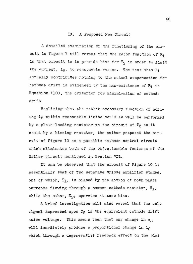
IX. A Proposed New Circuit
A detailed examination of the functioning of the cir
cuit in Figure I will reveal that the major function of Rlin that circuit is to provide bias for TZ in order to limit
the current, i 2 , to reasonable values. The fact that Rl
actually contributes nothing to the actual compensation for
cathode drift is evidenced by the non-existence of Rl in
E uation (10), the criterion for minimization of cathode
drift.
Realizing that the rather secondary function of hold
ing i2 within reasonable limits could as well be performed
by a plate-loading resistor in the circuit of T2 as it
could by a biasing resistor, the author proposed the cir
cuit of Figure 10 as a possible cathOde control circuit
which eliminates both of the objectionable features of the
Miller circuit mentioned in Section VII.
It can be observed that the circuit of Figure 10 is
essentially that of two separate triode amplifier at ges,
one of which, Tl' 1s biased by the action of both plate
currents flowing through a common cathode resistor, RK'
while the other, T2 , operates at zero bias.
A brief investigation will also reveal that the only
signal impressed upon T2 is the eqUivalent cathode drift
noise voltage. This means then that any change in en
will immediately produce a proportional change in i 2
which through a degenerative feedback effect on the bias

--. b
--
he Proposed 01rcu1t ho1r1ngthe Eq1l1Talent aathode Dr1ft R011e Voltage ner t ,en
r1gure 10

42
of TI , will tend to nullify the cathode drift effect on TI-
It can be observed that this circuit, unlike the Miller
circuit, does not produce a negative feedback effect on T2
since no amount of change in i 2 or i l can affect the zero
bias on T2 . It can also be observed that the use of RL2
provides the possibility of using a common plate-supply
voltage, thereby appreciably simplifying the po,~r supply
requirements.

43
X. Mathematical Analysis of TheProposed Circuit
Having proposed the circuit of Figure la, it seemed in
order to analyze it in the manner of Section III in order to
c.etermlne whether criteria existed for ~ =0; 80 the A-Coen
equivalent circuit of Figure 11 was c.rawn to be used as a
basis for the analysis. The symbols used in Figure 11 are
defined below and they will be used. 'throughout the ensu.ing
c.iscussion of the proposed circuit:
rl = Plate resistance of T1
rZ = Plate resistance of TZ
RK • Cathode Resistor
RLl • Load resistance on T1
RL2 = Loati resistance on TZ
\.11 = Amplification factor of T1
J.L2 = Amplification factor of TZ
egl = Input signal for Tl
egZ = Input signal for TZ
en • Equivalent cathode c.rift noise volta.ge
i1 = Plate current of T1
i 2 = Plate current of T2
Assuming that the grid of Tl was grounded, the follow
ing observations were made from Figure 10:
. . .
. . .(20)
(21)

•'" -------oI\J\JV,~f\_--__I
~.
2
A-CJ Sq 1.nJ.eD' 0170u1' tor th Pro 01.4 01 us.·
rigure 11

45
Using Equa"tion (20) and summing voltages around the top
loop of Figure ·11 yielded the following expression:
~l[(ll + 12 )RK - en] = en -(11 + 12 )RK - 11 (RLl + r l )
Expanding and collecting terms:
(~l + l)en = ll[(~l + l)RK + RLl + rl]
+ i2(~1 + l)RK ..• (22)
Using Equation (21) and Bumming voltages around the
bottom loop of Figure 11 yielded the following expression:
- ~2en = en - (il + i 2 )RK - i 2 {RL2 + 1.'2)
Expanding and collecting terms:
(~2 + l)en : ilRK + i 2 (RL2 + RK + r2) ... (23)
Solving Eauation.s (22) and (23) for 11 by determinants:
(~1 + l)en -. (~1 + l)RK
_(i-12 + 1) E3 n...:...:. (RLZ + RK + 1.'2)Denominator
In order to ~etermine
hand side of Equation
Or, since the denominator obviously is a constant:(~1 + 1) (RL2 + RK + rZ)en
K
(~2 + 1)(~1 + 1)RX enK
(~l + 1) (RL2 + RK + rZ) - (~+ 1)(~1 + l)RKK
(24)()ila criterion for ~ = 0, the rightoen. . .
(24) was lequated to zero, and since
(~1 + 1) ~ 0 and K must be finite:
o - RL2 + RK + r2 - (~ + l)RK
or;
• • • (25)

where gm2 equals the transconductance of T2•
46

47
XI. Graphical Analysis of The Proposed Circuit
With the derivation of Equation (25) the ability of the
proposed circuit to compensate for cathode drift effects
seemed assured; consequently there remained only the problem
of selecting circuit values which would permit the estab
lishment of reasonable operating points for the two tubes,
Tl and T2, and which at the same time would satisfy the
necessary condition for cathode contrOl, R = RL2 + -1-K ~2 gm2"
The selection of such values again resolved into a
trial-and-error type of graphical solution similar to that
of Sections IV and V. It is with the exact nature of this
solution that this section will be concerned.
A 68L7 tube was again used with a value for RLl of 1
megohm and an assumed grid bias for Tl of -3 volts; con
sequently on the characteristic curves for this tube a load
line representing 106 ohms and passing through the assumed
plate supply voltage, 2b5 volts, was drawn as AB in Figure
12. Point C in Figure 12 represents the assumed operating
point for TI •
Assuming a plate current, i2, of 4 milliamperes for
the control tUbe, an operating point for this tube was
automatically established as Point D in Figure 12 since it
was known that this point must lie on the zero bias curve;
consequently the load line for this tube was drawn by con
necting the operating point, D, with the common plate sup
ply voltage, 255 volts, at Point A.

2 8
Plate200 250
Gr ph10al Oonstruotionfor the Propos d 0irouit Using 6SL7 !ube
F1gur 12

49
Taking the reciprocal of the slope of line AD provided
the value:
RL2 = 18700 ohms (26)
• • • (27)
• • • (28)
Now, realizing that the 3 volts of grid bias on T1 must
be provided by the sum of the two plate currents floWing
through RK, it can be seen thatECIRK = "=""'"'=---:.-11 + 12
Where ECI = the grid bias on TI'
But:
EC1 = 3 volts by assumption
i2 = 4 x 10⁻³ amperes by assumption
and:
11 ~ .125 x 10-3 amperes from Figure 12
So:3 x 10³
RK = 4 + .125
• 728 ohms.
From Equat on (25), hOlever,RI,2 1
RK=-+-1J.2 gm2
So substituting from Equations (26) and (27) into Equation
(28), and since IJ. for a 6SL? equals ?O:
728 = 18700 + -1-70 gm2
or:
..J:... = 461 ohmsgm2
• • • (29)

50
In other words, if the foregoing choice of an operating
point for T2 Was such that the reciprocal of the transcon
ductance of the tube at that point is 461 ohms, then the
circuit values selected in this solution when employed in
the circuit of Figure 10 should produce a cathode control
oi cui t in which ~il approaches zero.oen
By taking the reciprocal of the slope of the zero bias
curve at Poln't D and divlding it by IJ. it was found that at
Point D:
close to the
l = 492gm2
This valu.e was believed to be sUfficiently
. . • (30)
value found in Equation (29) to justify using the circuit
constants which had been obtained by this analysis.
It of course is apparent that the choice of an operat-
ing point for TZ in this procedure will not always lead to
the fortun.ate agreement between Equations (29) and (30)
that was found in this case. In fact it was not the
author's good fortune to find such immediate agreement with
his first choice of this operating point; consequently, as
haa undoubtedly been surmised, it was necessary to duplicate
the foregoing work a number of times, each ti.me using a dif
ferent set of assumed starting values, before the happy
coincidence of agreement between Equations (29) and (30) was
reached. The solution given here, then, is only the last
one of a large number of previous attempts.

The circuit constants obtained from tr~s analysis are
summ ized below:
RK ::a 728 ohms
RLl = 106 ohms
RL2 = 18700 ohms
Ebbl • Ebb2 = 255 volts
51

52
XII. Some Seeming Limitations of TheProposed Circuit
An examination of Figure 12 will immediately reveal
that, inherent in the final solution in Section XI, is an
operating point for Tl which allows only a very small grid
signal swing (about + 0.75 volt ), if relatively distor
tion-free operation is to be accomplished; it is signifi
cant in this respect that even though the author tried a
large number of different initial assumptions he was not
able to arrive at a set of circuit constants which would
avoid this near-cutoff operating point for Tl so long as a
6SL7 tube was employed.
A critical analysis of the manner in which Equation
(25) fits into the graphical solution of Section XI to
determine the operating point of Tl revealed the possibil
ity that the above limitation might be avoided if some
tube having a large transconductance lere employed.
By examining several sets of tube characteristics it
was discovered that a 6J6 has a transconductance which will
range from three to four times as large as the transcon
nuctance of a 6SL7; so it was proposed to repeat the work
of Section XI for a 6J6 employed in the circuit of Figure
10. The circuit constants obtained from this work (the com
plete analysis is contained in Appendix B) were as follows:
RK ::a 585 ohms
RLl = 255000 ohms

53
RL2 = 16350 ohms
Ebbl = Ebb2 =255 volts
These circuit values gave a bias of -6.43 volts on T1
hlch, as can be seen in Appendix B, permits a grid sWing of
2 or perhaps 3 volts before the region of high aistort1on 1s
invaded.

54
XIII. Experimental ork on TheProposed Circuit
In order to determine whether and to what extent the
proposed circuit would compensate for cathode drift effects,
a program of experimentation essentially the same as that of
Section VI was initiated. The circuit employed was similar
to that of Figure 5, the difference being, as shown in
Figure 13, that the actual circuit undergoing test was the
proposed circuit of Figure 10 rather than the Miller circuit
of Figure 1.
All test apparatus was the same as is listed in Section
VII.
In Run Number I, using a 6SL7 as the tube in Figure 13
and with the circuit constants essentially as found in Sec-
tion XI, data for heater voltage versus output volt ge as
taken s the heater voltage was varied from about 10% below
to about 10% above some reference value near to rated volt
age. These data are contained in Appendix C and are plotted
as Curve Number 1 in Figure 14.
In order to get a comparison of compensated versus un-
compensated performance the data for Curve Number 3 of Fig
ure 6 (which it will be recalled is for an uncompensated
6SL?) was replotted as Curve Number 2 on Figure 14. It is
believed that a comparison of these two curves will amply
attest the fact that the proposed circuit provides excellent
compensation over a wide range of heater voltage limits.

.......-..o..c +Potent1o
t
--
To He t re
!he! t Oirou1t U d 1th the Prop08ed C1rou1t
'1 e 13

o +2 +8 +r Volt O!W1P
Drlt Our • tor the Propo e4 Circuit U81ng a SSL7 tube
figure 14

57
In Run Number 2 the 6SL7 of Run Number 1 was replaoed
by an RCA 6J6 tube, and the circuit constants were changed
to cor espond essentially to those found in Section XII;
then, data of heater voltage versus output voltage were
ag in taken over a range of heater voltage from about 10%
below to about 10% above a reference value near rated
voltage. These data are plotted as Curve umber 1 in
Figure 15.
With the grid, plate, cathode, and heater of T2 dis
connected from the circuit and grounded, and ith RK
adjusted to produoe the same bias on Tl as existed in Run
Number 2, data for a 6J6 single unit triode stage was taken
in the same manner as was employed in Run umber 2. These
data are plotted in Figure 15 as Curve Number 2.
It is believed that Figure 15 stands as further evi
dence of the ability of the proposed circuit to compensate
for cathode drift effects.
It is also believed that the oompensation achieved
with a 6J6, having an allow ble low distortion grid voltage
s ~ng of 2 or 3 volts, fUlly demonstrates that the limita
tions of the proposed circuit, as they were discussed in
Section XII, are actUally limitations on the applicability
of a specific tube rather than inherent characteristics of
the circuit itself.

~::j0,~
::jo(.)I
Q
~-
1
- ~. 5= ~--I:-:,-L._-L_.J..._-'-_.L-_&--I_..iQ.-20-16-12-8 - 4 0 +4 +8 +12+16+20
Perce~t Heater Voltage C.ange
Drift OurT' tor the Proposed 0irouit Using 8 aJ6 fube
19ure 15

59
XIV. Summary and Conclusions
It is believed that the conclusions to be dra~m from
this work can be quite simply stated as follows:
A. The former belief that the amplifier load resist
ance must be large in order for the Miller circuit
to affect cathode control has been shown to be
without justification.
B. There has been developed a ne circuit for cathode
control which not only eliminates a source of
noise voltage (one cathode resistor) at a low
voltage level in the circuit but also eliminates
the double plate supply voltage requirement which
is associated with many eXisting cathode control
circuits. This circuit is original with this paper
to the best of the author's knowledge.
In connection with subparagraph A above it is important
to point out that the earlier belief, that RL in Figure 1
must be large, represented a serious limitation on the
applicability of an excellent circuit to problems requiring
wide frequency response.
When it is observed that many of the applications of
D-C amplifiers, as in high quality cathode ray oscillo
scopes, combine the difficult requirements of high stability
and wide frequency response it can be readily realized that
many valuable applications of the low cathode drift effect
of the Miller circuit would never be made if the circuit

60
were one with which only relatively narrow frequency
response were possible.
\fhile it is not intended to demonstrate that the new
circuit of subparagraph B above is generally superior to
either the Miller circuit or to any other cathode-control
circuit, it is believed that its single plate supply volt
age requirement will constitute a distinct advantage in
many applications.
The importance of the removal of one cathode resistor
can best be emphasized by observing that in numerous appli
cations of D-C amplifiers, suoh as in the investigation of
voltages generated by animal nervous systems, the order of
magnitude of the voltages being studied might easily be the
same as or even les8 than that of the noise voltages gener
ated in a cathode resistor.

Appendix A
Table I
Drift Data for Miller Circuit HavingA 106 ohm Load Resistor
61
Change inHeater Voltage
(% of Rated)
- 9.53
- 6.35
- 3.18
o
+ 3.18
+ 6.35
+ 9.53
Change inOutput Voltage
(% of Reference*)
+ .542
+ .407
+ .127
o
- .095
- .218
- .437
~The reference value of output voltage
was taken as that value which existed
at 0% change in heater voltage.

Table II
Drift Data for ller Circuit Having40K ohm Load Resistor
62
Change ineater Voltage
(% of Rated)
- 9.53
- 6.35
- 3.18
o
+ 3.18
+ 6.35
+ 9.53
Change inOutput Voltage
(% of Referencek )
+ .157
+ .099
+ .054
o
- .095
- .197
- .285
*The reference value of output voltage
was taken as that value hich existed
at 0% change in heater voltage.

Table III
Drift Data For Conventional TriodeAmplifier Using a 6SL? Tube
63
Change inHeater Voltage
(% of Rated)
- 9.53
- 6.35
- 3.18
o
+ 3.18
+ 6.35
+ 9.53
Change inOutput Voltage
(% of Referencek )
+ 4.32
+ 2.93
+ 1.41
o
- 1.39
- 2.62
- 3.98
*The reference value of output voltage
was taken as that value which existed
at 0% change in heater voltage.

64
Appendix B
Graphical Analysis For A 6J6 Tube Used In TheProposed Cathode Control Circuit
Using the characteristic curves for a 6J6 dual triode
a load line for a 255,OOO-ohm load resistance was drawn as
AB in Figure 16.
A plate current, iI' for Tl was assumed to be 0.4 mil
liamperes, thereby establishing an assumed operating point
on the -6 volt bias line at C in Figure 16.
Assuming a plate current, i2, of 10.6 milliamperes for
T2 established the load line AD in Figure 16. This line
represents a load resistor, RLe , of 16,350 ohms.
Taking the reciprocal of the slope of the zero bias
curve at Point D provided a value of 5880 ohms for the plate
resistance, r2' of T2'
Substituting the foregoing values for RLe and rZ into
E uation (25) and observing that ~ for a 6J6 equals 38, a
value for RK was obtained as follows:
~2+~=
~2
=16350 + 588038
• 585 ohms
In order to determine whether the foregoing values
would produce proper operating conditions it was only neces
sary to see whether the above value of RK,would produce the

Or phloal Construotionsfor the Proposed Cirouit Using a 6J6 ~ube
Figure 16

originally assumed value of bias on Tli so, observing that
the bias on Tl' ECl' is developed by the sum of the two
plate currents flowing through RK:
ECI = (il + i2)RK
66
Substituting from above:
Eel = (0.4 + 10.6) x 585 x 103
= 6.43 volts
This value deviates slightly from the originally
assumed value of 6 volts, but it can be observed that this
deviation serves solely to introduce a negligible change in
the plate current of TI' and even if 11 were changed by
100%, no appreciable difference would be observed in the
calculated bias of 6.43 volts; therefore the foregoing
solution was deemed to be acceptable.

Appendix C
Table IV
Drift D ta For The Proposed CircuitUsing a 6SL7 Tube
67
Change inHeater Voltage
(% of Rated)
- 9.53
- 6.35
- 3.18
o
+ 3.18
+ 6.35
+ 9.53
Change inOutput Voltage
(% of Reference*)
- .176
- .120
- .051
o
+ .038
+ .087
o
*The reference value of output voltage
was taken as that value which existed
at 0% change in heater voltage.

Table V
Drift Data For The Proposed CircuitUsing a 6J6 Tube
68
Change inHeater Voltage
(% of Reference*)
- 13.5
6.79
o
+ 6.79
+ 13.5
+ 20.4
Change inOutput Voltage
(% of Reference")
- .355
- .055
o
- .163
- .598
-1.35
*Reference heater voltage was taken as
5.9 volts since that was the apparent
point of zero slope of the curve.
**Refereuce output voltage was taken as
the value that existed at Reference
heater voltage.

Table VI
Drift Dat For A Conventional TriodeAmplifier Using a 6J6 Tube
69
Change inHeater Voltage
(% of Reference·)
- 13.5
6.79
o
+ 6.79
+ 13.5
+ 20.4
Change inOutput Voltage
(% of Reference·)
+ 1.46
+ .62
o
.81
- 1.67
- 2.43
*The reference values used here were
the same as those used for Table V.

70
Bibliography
Artzt, Maurice. Survey of D-C amplifiers. Electronics.Vol. 18, Aug. 1945, pp. 112-118.
Batcher, R. R., and Mou1ic, W. The electronic engineeringhandbook. N.Y., Electronic Development Associates, 1944.pp. 188-191 and 298-300.
Black, L. J., and Scott, H. J. A direct-current and audiofrequency amplifier. Proceedings of I.R.E. Vol. 28, June1940, pp. 269-271.
Ginzton, E. L. D-C amplifier design technique.Electronics. Vol. 17, March 1944, pp. 98-102.
Goldberg, H. A high gain d-c amplifier for bioelectricrecording. Electrical Engineering. Vol. 59, Jan. 1940,pp. 60-64.
Miller, S. E. Sensitive d-c amplifier with a-c operation.Electronics. Vol. 14, Nov. 1941, pp. 27-31 nd 105-109.
Shaney, A. C. All push-pull direct-coupled 10-watt amplifier. Radio-Craft. Vol. XI, July 1939, pp. 16-18 and57-59.
Va~ley, G. E. Jr., and Wallman, H. Vacuum tube amplifiers.N. Y., McGraw-Hill, 1948. pp. 409-491 and 730-731.
Yu, Y. P. Cathode follower coupling in d-c amplifiers.Electronics. Vol. 19, Aug. 1946, pp. 99-103.

71
Vita
The author was born on a farm about 8 miles we8~ of
Neosho, Missouri in Newton County on January 22, 1917
His pre-college education was obtained in the pub 0
sohools of Springfield, Missouri between the years 1922 and
1934.
In 1934 he entered Drury College in Springfield where
he pursued a pre-engineering type of training until 1936
when he transferred to Purdue University. He graduated
from Purdue with the degree of Baohe1or of Science in
Electrical Engineering in 1939.
From 1939 until 1943 he was employed by James R.
Kearney Corporation of St. Louis, Missouri in various
capacities as an engineer.
In 1943 he was commissioned a Second Lieutenant in the
Signal Corps of the U. S. Army. He became a Captain in the
Active Reserve of the Officers' Reserve Corps upon his
separation from active duty in 1946.
In 1947 he became an Instructor at the School of Mines
and Metallurgy of the University of Missouri in which capac
ity he still serves.