a strain energy density theory for mixed...
TRANSCRIPT
JOURNAL OF THEORETICAL
AND APPLIED MECHANICS
54, 4, pp. 1417-1431, Warsaw 2016DOI: 10.15632/jtam-pl.54.4.1417
A STRAIN ENERGY DENSITY THEORY FOR MIXED MODE CRACKPROPAGATION IN RUBBER-LIKE MATERIALS
Abdelkader Boulenouar
Djillali Liabes University of Sidi Bel-Abbes, Mechanical Engineering Department, Laboratory of Materials and Reactive
Systems, Larbi Ben Mhidi, Algeria; e-mail: aek [email protected]
Noureddine Benseddiq
Mechanics Laboratory of Lille, CNRS UMR 8107, Ecole Polytech’Lille, University of Lille, France
Mohamed Merzoug, Nabil Benamara, Mohamed Mazari
Djillali Liabes University of Sidi Bel-Abbes, Mechanics and Physics of Materials Laboratory, Larbi Ben Mhidi, Algeria
In this paper, a numerical modeling of crack propagation for rubber-like materials is presen-ted. This technique aims at simulating the crack growth under mixed-mode loading basedon the strain energy density approach. At each crack increment length, the kinking angle isevaluated as a function of the minimum strain energy density (MSED) around the crack tip,using the Ansys Parametric Design Language (APDL). In this work, numerical examples areillustrated to demonstrate the effectiveness, robustness and accuracy of the computationalalgorithm to predict the crack propagation path. The results obtained show that the plan ofcrack propagation is perpendicular to the direction of the maximum principal stretch. Mo-reover, in the framework of linear elastic fracture mechanics (LEFM), the minimum valuesof the density are reached at the points corresponding to the crack propagation direction.
Keywords: strain energy density, mixed mode, hyper-elastic, crack propagation
1. Introduction
Today rubbers are used in many engineering industries. The demand for such materials andtheir performance is continually increasing. The performance is limited, among other factors,by the initiation of cracks. Hence, it is necessary to develop procedures that allow an exactdetermination of a fracture criterion of these materials. To study fracture rubbers we can usetwo approaches: the global approach and the local approach. The global approach of the frac-ture mechanics, originated from Griffith (1920, 1924), represents a good method allowing thecharacterisation of the materials fracture. It assumes that initiation and growth of cracks beginfrom pre-existing defects in the structure. In the ’50s, Rivlin and Thomas (1953) generalized theGriffith’s energy approach and defined the concept of tearing energy T as the energy releasedper unit area of crack surface growth. The parameter T can be calculated analytically from a fewspecimen geometries proposed by several authors (Rivlin et Thomas, 1953; Greensmith, 1963;Andrews, 1974).The global energy approach is used qualitatively to characterize the rupture of materials
under simple loading (mode I); it is not adapted for complex loadings (mode I+II). In this case,the quantitative local approach represents a good alternative which makes it possible to indicatethe crack initiation and direction.In linear elastic fracture mechanics, the various fracture criteria for cracks subjected to mixed
mode loading have been introduced for the determination of the propagation direction and thecritical stress such as the maximum tangential stress criterion (Erdogan and Sih, 1963; Chang,1981; Maiti and Smith, 1983), maximum principal tangential stress criterion (Maiti et Smith,
1418 A. Boulenouar et al.
1983), maximum strain criterion (Wu, 1974; Chang, 1981), and strain energy density criterion(Sih, 1974; Theocaris, 1984). Almost all these criteria postulate that crack initiation occurs atthe crack tip and propagate towards the radial direction.Sih’s (Sih, 1973, 1974; Sih and Macdonald, 1974; Kipp and Sih, 1975) strain energy density
criterion (SEDC) assumes the strain energy density to be investigated for an element aroundthe crack tip as the starting point and the strain energy density factor as a basic parameter. Itis then postulated that crack initiation will occur at the crack tip in the radial direction alongwhich the strain energy density factor S is minimum, and the crack will begin to propagatewhen the factor S reaches some critical value.The strain energy density criterion was validated experimentally and numerically on fragile
materials (Theocaris, 1984; Boulenouar et al., 2016, 2013a; Benouis et al., 2015; Ayatollahi andSedighiani, 2012; Pegorin et al., 2012; Choi et al., 2006) and ductile materials (Komori, 2005;Chow and Xu, 1985; Carpinteri, 1984). In the framework of large deformations, this criterionwas used by Hamdi et al. (2007) on filled rubber materials to predict the initial crack orientationof a central crack.The objective of this paper is to present the numerical modeling of the crack propagation tra-
jectory for rubber-like materials. Using the Ansys Parametric Design Language (APDL) (2006),the crack direction is evaluated as a function of the minimum strain energy density (dW/dV )minaround the crack tip. The numerical examples are included to illustrate the validation of thenumerical approach for crack growth simulation in hyper-elastic materials.
2. The strain energy density theory
The SED fracture criterion locally focuses on the continuum element ahead of the crack and isbased on the notion of weakness or severity experienced by the local material. Failure occurswhen the critical amount of strain energy dW is accumulated within the element volume dVand the crack is then advanced incrementally in the corresponding direction (Sih, 1974; Sih andBarthelemy, 1980). The strain energy density function dW/dV is assumed to have the followingform
dW
dV=S
r(2.1)
where S is the strain energy density factor and r is the distance from the crack tip. The minimumof the strain energy density factor Smin around the crack tip determines the likely direction ofcrack propagation.The strain energy density can be determined directly from the relationship
dW
dV=1
2σT ε (2.2)
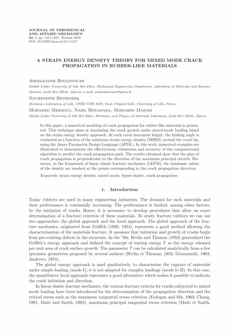
The computed discrete values for S are then fitted with an approximation function which ena-bles simple determination of the local minimum. The strain density function has several localminimuma around the crack tip, where the global minimum is not necessarily the true solution,as it can be observed in Fig. 1.The physically meaningful minimum of the strain density function Smin can be found nu-
merically by incremental search for a local minimum in possible crack extension directions θi inthe range ±π around the crack tip (Fajdiga et al., 2007).Fajdiga et al. (2007) used the position of integration points to define the corresponding angle
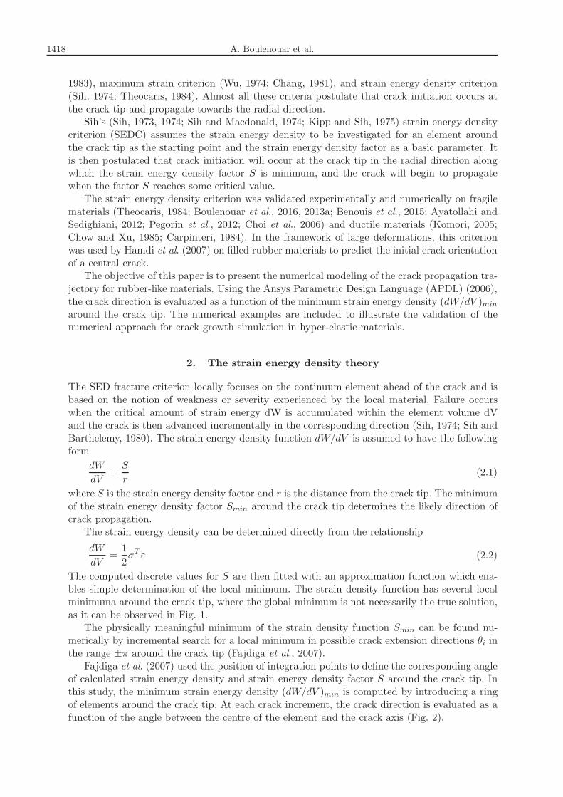
of calculated strain energy density and strain energy density factor S around the crack tip. Inthis study, the minimum strain energy density (dW/dV )min is computed by introducing a ringof elements around the crack tip. At each crack increment, the crack direction is evaluated as afunction of the angle between the centre of the element and the crack axis (Fig. 2).
A strain energy density theory for mixed mode crack... 1419
Fig. 1. Strain energy density factor S as a function of the angle θ
Fig. 2. Direction of propagation using the minimum strain energy density
2.1. Modeling of the hyperelasticity
The mechanical behavior of rubber materials is generally described using a hyper-elasticformalism defined by a function dW/dV called the strain energy density. The establishment ofthe law of this behavior is a necessary step to perform analytical and/or numerical calculations todevelop or exploit multiaxial tests. These behavior laws should be specific to the strain ultimatelevels and should allow description of multiaxial loadings accurately.
In this study, we based on the experimental data of Hamdi et al. (2006), Hamdi (2006) usingfour tests: uniaxial tension (UT), uniaxial compression (UC), pure shear (PS) and equibiaxialtension (ET). The tests were performed on two rubber materials: natural rubber and styrenebutadiene rubber.
Based on these tests, the rubber materials are modeled by a hyperelastic potential developedfor quasi-incompressible rubbers using Yeoh’s model (Yeoh, 1990), Eq. (2.3)1, for natural rubberNR and Ogden’s model (Ogden, 1984), Eq. (2.3)2, for Styrene Butadiene rubber SBR
dW
dV= C10(I1 − 3) + C20(I1 − 3)
2 + C30(I1 − 3)3
dW
dV=N∑
k=1
µkαk(λακ1 + λ
ακ
2 + λακ
3 − 3)(2.3)
where dW/dV is strain energy density, C10, C20, C30, µk, αk are material parameters to bedetermined, λ1, λ2 and λ3 are principal extensions.
The hyper-elastic coefficients of the studied materials are given in Table 1.
Table 1. Values of the material parameters values (Hamdi et al., 2006; Hamdi, 2006)
Materials Material parameters
NR C10 [MPa] C20 [MPa] C30 [MPa]0.298 0.014 0.00016
SBR µ1 [MPa] α1 µ2 [MPa] α20.638 3.03 −0.025 −2.35
1420 A. Boulenouar et al.
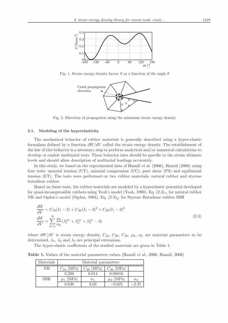
The relevance of these material models was evaluated by Hamdi (Figs. 3a and 3b) for differentloading (UT, UC, ET and PS), comparing the calculated stress-strain analytically with thoseobtained from the experiment.
Fig. 3. Engineering stress-strain evolution for NR (left) and SBR (right) (Hamdi et al., 2006; Hamdi,2006; Boulenouar and Mazari, 2009)
2.2. Finite element modeling and crack growth algorithm
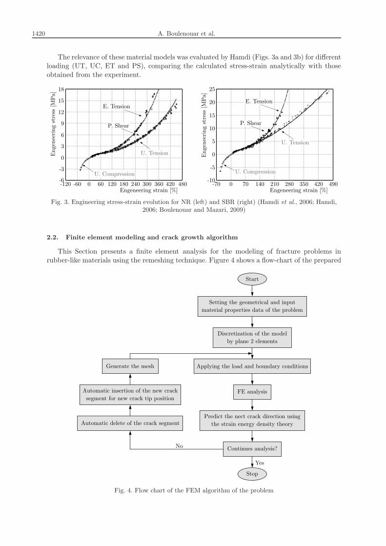
This Section presents a finite element analysis for the modeling of fracture problems inrubber-like materials using the remeshing technique. Figure 4 shows a flow-chart of the prepared
Fig. 4. Flow chart of the FEM algorithm of the problem
A strain energy density theory for mixed mode crack... 1421
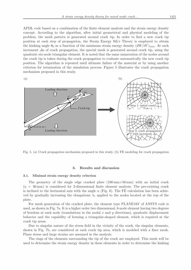
APDL code based on a combination of the finite element analysis and the strain energy densityconcept. According to the algorithm, after initial geometrical and physical modeling of theproblem, the mesh pattern is generated around crack tip. In order to find a new crack tipposition at each step of propagation, the Strain Energy Sih’s Theory is employed to obtainthe kinking angle θ0 as a function of the minimum strain energy density (dW/dV )min. At eachincrement ∆a of crack propagation, the special mesh is generated around crack tip, using thequadratic six-node triangular element. It is noted that the same numeration of the nodes aroundthe crack tip is taken during the crack propagation to evaluate automatically the new crack tipposition. The algorithm is repeated until ultimate failure of the material or by using anothercriterion for termination of the simulation process. Figure 5 illustrates the crack propagationmechanism proposed in this study.
Fig. 5. (a) Crack propagation mechanism proposed in this study, (b) FE modeling for crack propagation
3. Results and discussion
3.1. Minimal strain energy density criterion
The geometry of the single edge cracked plate (100mm×50mm) with an initial crack(a = 30mm) is considered for 2-dimensional finite element analysis. The pre-existing crackis inclined to the horizontal axis with the angle α (Fig. 6). The FE calculation has been achie-ved by gradually increasing the elongations λ1 applied to the nodes located at the top of theplate.For mesh generation of the cracked plate, the element type PLANE183’ of ANSYS code is
used, as shown in Fig. 7a. It is a higher order two dimensional, 8-node element having two degreesof freedom at each node (translations in the nodal x and y directions), quadratic displacementbehavior and the capability of forming a triangular-shaped element, which is required at thecrack tip areas.Due to singular nature of the stress field in the vicinity of the crack, the singular elements,
shown in Fig. 7b, are considered at each crack tip area, which is modeled with a finer mesh.Plane stress and large strains are assumed in the analysis.The rings of the elements surrounding the tip of the crack are employed. This mesh will be
used to determine the strain energy density in these elements in order to determine the kinking

1422 A. Boulenouar et al.
Fig. 6. Geometry of the single edge cracked plate
Fig. 7. (a) PLANE183 eight-node finite element and (b) singular option
Fig. 8. Description of the parameters r, α and θ
angle θ in the direction for which this energy density is minimal (dW/dV )min. Figure 8 illustratesdescription of the parameters r, α and θ, where r is the distance from the crack-tip, α is thecrack inclination angle and θ is the kinking angle.
The specifications of the crack tip mesh and a close up view for the crack inclination angleα = −30◦ are shown in Fig. 9. In this figure, ri represents the distance between the crack tipand the center of the element c.
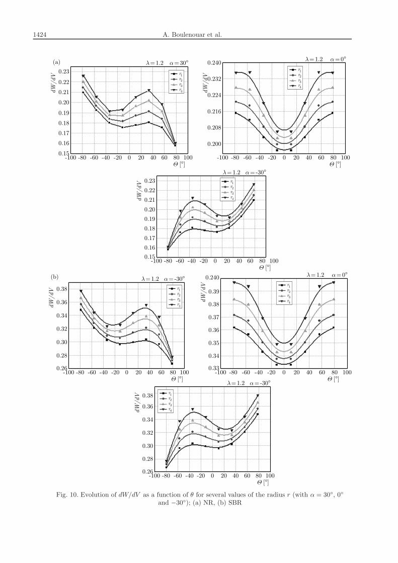
For the two materials studied NR and SBR, Figs. 10 show the evolution of the strain energydensity dW/dV as a function of the angle θ. The results obtained are traced for several values ofthe radius ri (1.25, 1.75, 2.5 and 3mm) and for three orientations of the initial crack α = 30
◦,0◦ and −30◦. These figures highlights that out of the core region surrounding the crack tip (inour case r ¬ r1), the minimum of dW/dV is reached for a constant value independently of thedistance r. The angle θ0 corresponds to the horizontal direction perpendicular to the loading. Itis noted that the observations obtained are similar to those obtained by Hamdi (2006).

A strain energy density theory for mixed mode crack... 1423
Fig. 9. The ring of elements around the crack tip
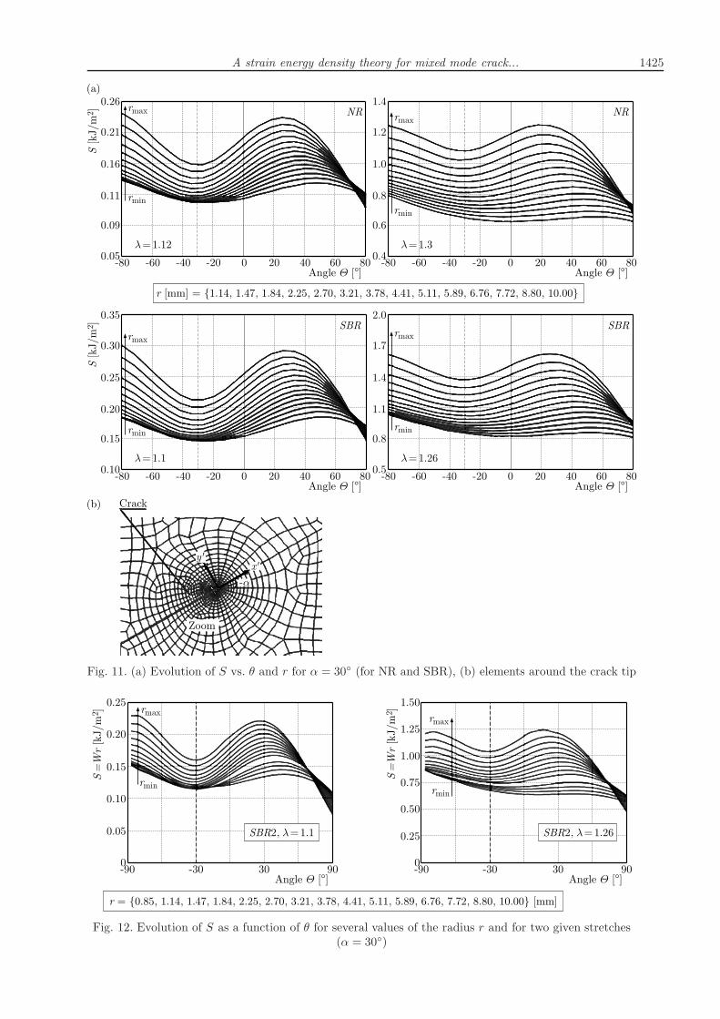
Figure 11a illustrates an example of the application of the SED approach in the case ofrubbers NR and SBR under mixed-mode loading. This figure shows the evolution of the pa-rameter S, called the strain-energy-density factor (with S = (dW/dV )r). The results obtainedare given vs. the radius ri and the polar angle θ for an inclination angle α = 30
◦. The curvesplotted in Fig. 11a show that out of the core region surrounding the crack-tip, the minimum ofthe parameter S is reached for a constant value independently of the radius r.
The angle equalizes here to−30◦, corresponding contrary to the value of the initial orientationof the crack (−α) calculated for the reference mark Ox′y′ (Fig. 11b). These results show a goodagreement with the results obtained by Hamdi et al. (2007) for other styrene butadiene rubberfilled with carbon black SBR2 (Fig. 12).
3.2. Effect of the number of elements surrounding the crack tip
For the strain energy density criterion, the precision is strongly related to the number ofelements surrounding crack tip zone. For this purpose, we examined the influence of the meshsize (or number of the elements) on the strain energy density variation. For that, the densitydW/dV is evaluated for different numbers of elements surrounding the crack tip. In this study,the numbers of elements considered are 16, 40 and 56 (Fig. 13).
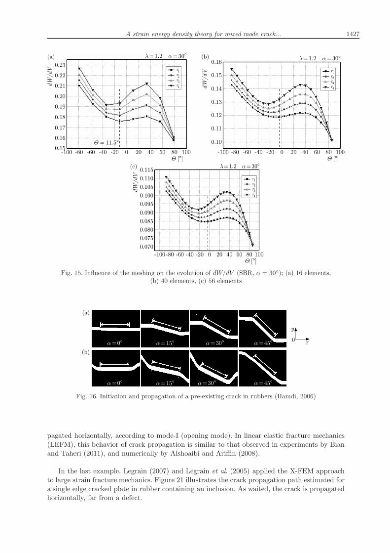
For different numbers of elements surrounding the crack tip zone and for several values ofthe radius r, Figs. 14 and 15 illustrate respectively for NR and SBR the evolution of the strainenergy density dW/dV as a function of the initial angle of crack propagation θ (with α = 30◦).The results obtained show that the precision is related to the elements size around the crack tip.
The results obtained are similar to those found in the case of a plate of rubbers (NR andSBR) containing a central crack (Hamdi, 2006) (Fig. 16). It is clear that this crack is propagatedaccording to the horizontal direction perpendicular to the loading direction and independently ofthe inclination angle α. Thus, the crack propagation direction is null, according to the referencemark of calculation (Oxy).
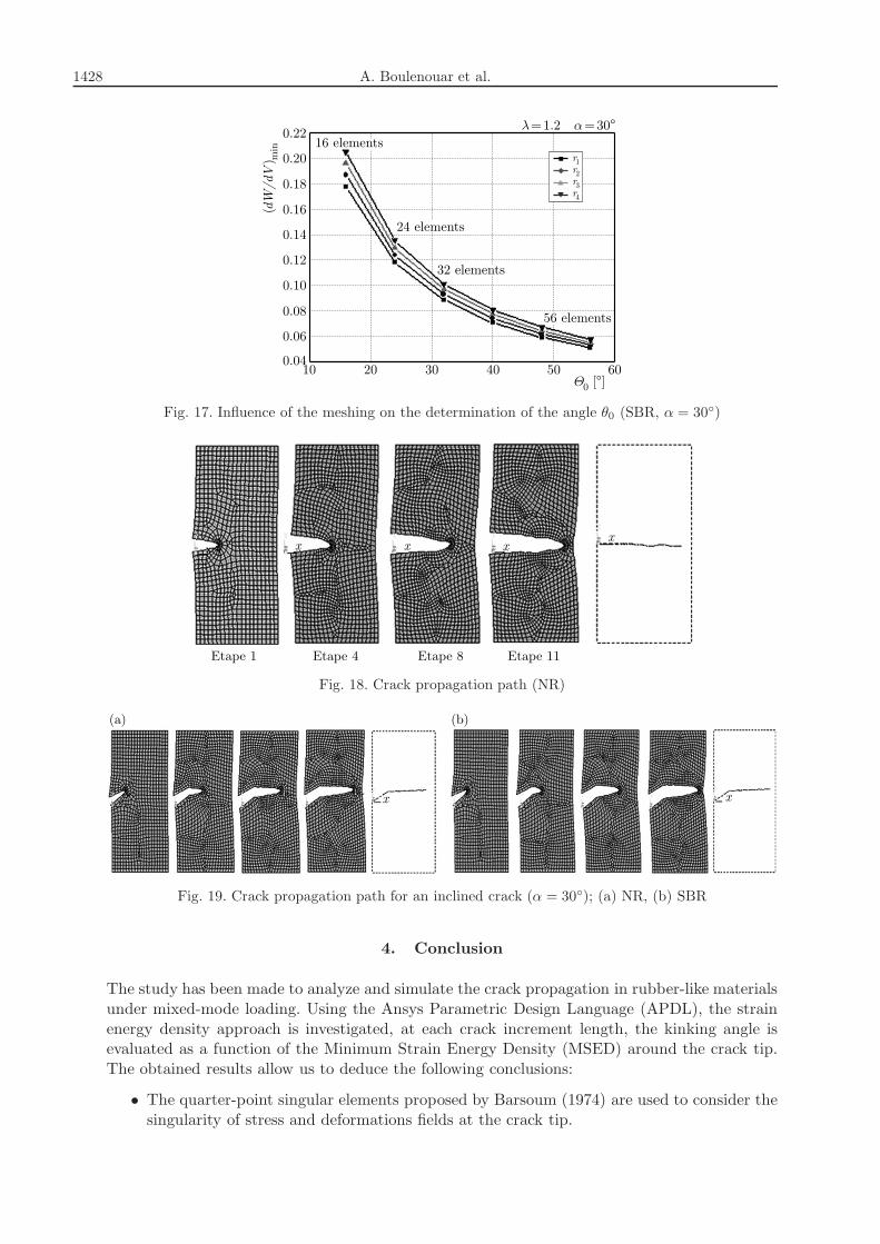
To better show the influence of the elements size around the crack tip on the determinationof the initial angle of crack propagation θ0, Fig. 17 illustrates the variation of the angle θ0 as afunction of (dW/dV )min for various numbers of elements surrounding the crack tip. The curvesobtained show more elements around the crack tip make the crack direction θ0 at each crackincrement length and the final path of crack propagation more precise.
3.3. Crack propagation path
In this Section, two simple examples are proposed to validate our model of the initial crackpropagation in rubber materials.
Figure 18 shows four steps for the extension of the initial crack (with α=0◦). As expected,
the crack propagates horizontally, depending on mode I loading. The results obtained allow us
1424 A. Boulenouar et al.
Fig. 10. Evolution of dW/dV as a function of θ for several values of the radius r (with α = 30◦, 0◦
and −30◦); (a) NR, (b) SBR
A strain energy density theory for mixed mode crack... 1425
Fig. 11. (a) Evolution of S vs. θ and r for α = 30◦ (for NR and SBR), (b) elements around the crack tip
Fig. 12. Evolution of S as a function of θ for several values of the radius r and for two given stretches(α = 30◦)

1426 A. Boulenouar et al.
Fig. 13. Elements sizes around the crack tip
Fig. 14. Influence of the meshing on the evolution of dW/dV (NR, α = 30◦); (a) 16 elements,(b) 40 elements, (c) 56 elements
to conclude that the criterion implemented gives a good crack path under mode I loading. Thiscrack propagation trajectory is similar to the observed in the case of elastic linear materials usingthe strain energy density approach (Boulenouar et al., 2013a, 2014) or another crack propagationcriterion (Boulenouar et al., 2013b; Alshoaibi and Ariffin, 2006).
In what follows, we propose to study the propagation path of a crack inclined to the horizontalaxis with an angle α = 30◦. The kinked angle and the crack propagation are made under planestress problems with the same loading conditions. Figure 19 presents four steps of the crackpropagation path. As expected, the crack reorients towards the vertical loads and propagateshorizontally until the end.
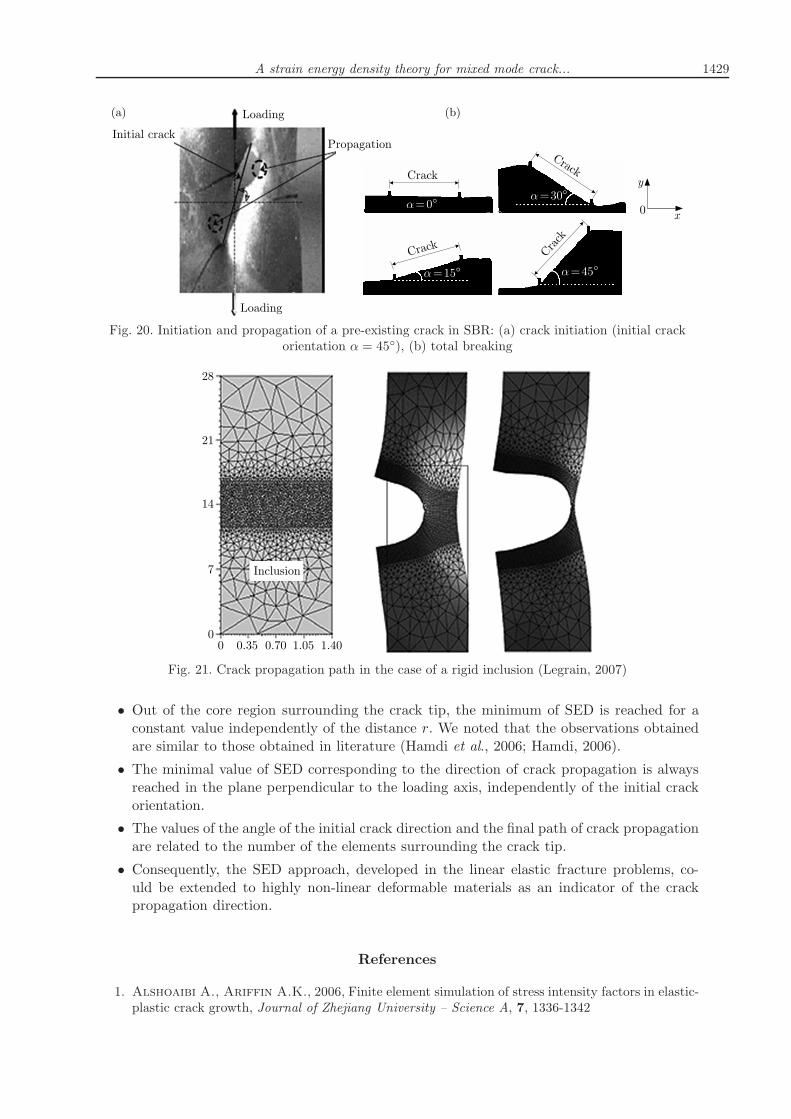
The same trajectory of crack propagation has been checked for another material elastomerpresented by Hamdi et al. (2007), see Fig. 20. The results obtained show that this crack is pro-
A strain energy density theory for mixed mode crack... 1427
Fig. 15. Influence of the meshing on the evolution of dW/dV (SBR, α = 30◦); (a) 16 elements,(b) 40 elements, (c) 56 elements
Fig. 16. Initiation and propagation of a pre-existing crack in rubbers (Hamdi, 2006)
pagated horizontally, according to mode-I (opening mode). In linear elastic fracture mechanics(LEFM), this behavior of crack propagation is similar to that observed in experiments by Bianand Taheri (2011), and numerically by Alshoaibi and Ariffin (2008).
In the last example, Legrain (2007) and Legrain et al. (2005) applied the X-FEM approachto large strain fracture mechanics. Figure 21 illustrates the crack propagation path estimated fora single edge cracked plate in rubber containing an inclusion. As waited, the crack is propagatedhorizontally, far from a defect.
1428 A. Boulenouar et al.
Fig. 17. Influence of the meshing on the determination of the angle θ0 (SBR, α = 30◦)
Fig. 18. Crack propagation path (NR)
Fig. 19. Crack propagation path for an inclined crack (α = 30◦); (a) NR, (b) SBR
4. Conclusion
The study has been made to analyze and simulate the crack propagation in rubber-like materialsunder mixed-mode loading. Using the Ansys Parametric Design Language (APDL), the strainenergy density approach is investigated, at each crack increment length, the kinking angle isevaluated as a function of the Minimum Strain Energy Density (MSED) around the crack tip.The obtained results allow us to deduce the following conclusions:
• The quarter-point singular elements proposed by Barsoum (1974) are used to consider thesingularity of stress and deformations fields at the crack tip.
A strain energy density theory for mixed mode crack... 1429
Fig. 20. Initiation and propagation of a pre-existing crack in SBR: (a) crack initiation (initial crackorientation α = 45◦), (b) total breaking
Fig. 21. Crack propagation path in the case of a rigid inclusion (Legrain, 2007)
• Out of the core region surrounding the crack tip, the minimum of SED is reached for aconstant value independently of the distance r. We noted that the observations obtainedare similar to those obtained in literature (Hamdi et al., 2006; Hamdi, 2006).
• The minimal value of SED corresponding to the direction of crack propagation is alwaysreached in the plane perpendicular to the loading axis, independently of the initial crackorientation.
• The values of the angle of the initial crack direction and the final path of crack propagationare related to the number of the elements surrounding the crack tip.
• Consequently, the SED approach, developed in the linear elastic fracture problems, co-uld be extended to highly non-linear deformable materials as an indicator of the crackpropagation direction.
References
1. Alshoaibi A., Ariffin A.K., 2006, Finite element simulation of stress intensity factors in elastic-plastic crack growth, Journal of Zhejiang University – Science A, 7, 1336-1342

1430 A. Boulenouar et al.
2. Alshoaibi A.M., Ariffin A.K., 2008. Fatigue life and crack path prediction in 2D structuralcomponents using an adaptive finite element strategy, International Journal of Mechanical andMaterials Engineering, 3, 1, 97-104
3. Andrews E.H., 1974, A generalised theory of fracture mechanics, Journal of Materials Science,9, 887-894
4. ANSYS, 2009, Inc. Programmer’s Manual for Mechnical APDL, Release 12.1
5. Ayatollahi M.R., Sedighiani K., 2012, Mode I fracture initiation in limestone by strain energydensity criterion, Journal of Theoretical and Applied Mechanic, 57, 14-18
6. Barsoum R.S., 1974, On the use of isoparametric finite element in linear fracture mechanics,International Journal for Numerical Methods in Engineering, 10, 25-37
7. Benouis A., Boulenouar A., Benseddiq N., Serier B., 2015, Numerical analysis of crack pro-pagation in cement PMMA: application of SED approach, Structural Engineering and Mechanics,55, 93-109
8. Bian L., Taheri F., 2011, A proposed maximum ratio criterion applied to mixed mode fatiguecrack propagation, Materials and Design, 32, 2066-2072
9. Boulenouar A., Benouis A., Benseddiq N., 2016, Numerical modelling of crack propagationin cement PMMA: Comparison of different criteria, Materials Research Bulletin, in press
10. Boulenouar A., Benseddiq N., Mazari M., 2013a, Strain energy density prediction of crackpropagation for 2D linear elastic materials, Journal of Theoretical and Applied Mechanic, 67/68,29-37
11. Boulenouar A., Benseddiq N., Mazari M., 2013b, Two-dimensional numerical estimation ofstress intensity factors and crack propagation in linear elastic analysis, Engineering, Technologyand Applied Science Research, ETASR, 3, 506-510
12. Boulenouar A., Benseddiq N., Mazari M., 2014, FE Model for linear-elastic mixed mode lo-ading: estimation of SIFs and crack propagation, Journal of Theoretical and Applied Mechanic, 52,373-383
13. Boulenouar A., Mazari M., 2009, Study of elastomers behavior at rupture based on the firstSeth strain measures invariant, Computational Materials Science, 45, 966-971
14. Carpinteri A., 1984, Size effects in material strength due to crack growth and material non-linearity, Journal of Theoretical and Applied Mechanic, 2, 39-45
15. Chang K.J., 1981a, Further studies of the maximum stress criterion on the angled crack problem,Engineering Fracture Mechanics, 14, 125
16. Chang K.J., 1981b, On the maximum strain criterion - a new approach to the angled crackproblem, Engineering Fracture Mechanics, 14, 107-124
17. Choi D.H., Choi H.Y., Lee D., 2006, Fatigue life prediction of in-plane gusset welded joints usingstrain energy density factor approach, Journal of Theoretical and Applied Mechanic, 45, 108-116
18. Chow C.L., Xu J., 1985, Application of the strain energy density criterion to ductile fracture,Journal of Theoretical and Applied Mechanic, 3, 185-191
19. Erdogan F., Sih G.C., 1963, On the crack extension in plates under plane loading and transverseshear, Journal of Basic Engineering, 85, 519-527
20. Fajdiga G., Ren Z., Kramar J., 2007, Comparison of virtual crack extension and strain energydensity methods applied to contact surface crack growth, Engineering Fracture Mechanics, 74,2721-2734
21. Greensmith H.W., 1963, Rupture of rubber-X. The change in stored energy on making a smallcut in a test piece held in simple extension, Journal of Applied Polymer Science, 7, 993-1002
22. Griffith A.A., 1920, The phenomenon of rupture and flow in solids, Philosophical Transactionsof the Royal Society A, 221, 163-198

A strain energy density theory for mixed mode crack... 1431
23. Griffith A.A., 1924, The theory of rupture, Proceedings of 1st International Conference forApplied Mechanics, Delft, 55-63
24. Hamdi A., 2006, Critere de rupture gnralis pour les elastomeres vulcanisables et thermoplastiques,These de doctorat, Universit des Sciences et Technologies de Lille
25. Hamdi A., Aıt Hocine N., Naıt Abdelaziz M., Benseddiq N., 2007, Fracture of elastomersunder static mixed mode: the strain-energy-density factor, International Journal of Fracture, 144,65-75
26. Hamdi A., Naıt Abdelaziz M., Aıt Hocine N., Benseddiq N., Heuillet P., 2006, Fracturecriteria of rubber like-materials under plane stress conditions, Polymer Testing, 25, 994-1005
27. Kipp M.E., Sih G.C., 1975, The strain energy density failure criterion applied to notched elasticsolids, International Journal of Solids and Structures, 11, 153-173
28. Komori K., 2005, Ductile fracture criteria for simulating shear by node separation method, Journalof Theoretical and Applied Mechanic, 43, 101-114
29. Legrain G., 2007, Extension de l’approche X-FEM aux grandes transformations pour la fissurationdes milieux hyperlastiques, These de Doctorat, Ecole Centrale Nantes, Universite de Nantes, France
30. Legrain G., Moes N., Verron E., 2005, Stress analysis around crack tips in finite strainproblems using the extended Finite Element Method, International Journal for Numerical Methodsin Engineering, 63, 2, 290-314
31. Maiti S.K., Smith R.A., 1983, Comparison of the criteria for mixed mode brittle fracture basedon the preinstability stress-strain field, International Journal of Fracture, 23, 281-295
32. Matic P., 1985, Numerically predicting ductile material behavior from tensile specimen response,Journal of Theoretical and Applied Mechanic, 4, 13-28
33. Ogden R.W., 1984, Non Linear Elastic Deformation, Ellis Horwood Limited Publishers
34. Pegorin F., Kotousov A., Berto F., Swain M.V., Sornsuwan T., 2012, Strain energy den-sity approach for failure evaluation of occlusal loaded ceramic tooth crowns, Journal of Theoreticaland Applied Mechanic, 5, 44-50
35. Rivlin R.S., Thomas A.G., 1953, Rupture of rubber. I. Characteristic energy for tearing, Journalof Polymer Science, 10, 291-318
36. Sih G.C., 1973, Some basic problems in fracture mechanics and new concepts, Engineering FractureMechanics, 5, 365-377
37. Sih G.C., 1974, Strain energy-density factor applied to mixed mode crack problems, InternationalJournal of Fracture, 10, 205
38. Sih G.C., Barthelemy B.M., 1980, Mixed mode fatigue crack growth predictions, EngineeringFracture Mechanics, 13, 439-451
39. Sih G.C., Macdonald B., 1974, Fracture mechanics applied to engineering problems – strainenergy density fracture criterion, Engineering Fracture Mechanics, 6, 361-386
40. Theocaris P.S., 1984, A higher-order approximation for the T-criterion of fracture in biaxialfields, Engineering Fracture Mechanics, 19, 975
41. Wu H.C., 1974, Dual failure criterion for plane concrete, Journal of the Engineering MechanicsDivision, 100, 1167
42. Yeoh O.H., 1990, Characterization of elastic properties of carbon black filled rubber vulcanizates,Rubber Chemistry and Technology, 63, 792-805
Manuscript received January 28, 2015; accepted for print April 15, 2016