a simple experiment with vmusbreadout - …docs.nscl.msu.edu/daq/newsite/samples/vmusbsetup...a...
TRANSCRIPT

A Simple Experiment withVMUSBReadout
Jeromy Tompkins

A Simple Experiment with VMUSBReadoutby Jeromy Tompkins
Revision History
Revision 1.0 March 11, 2015 Revised by: J.R.T.Original release
Table of Contents1. Introduction............................................................................................................................................12. Setting up the Electronics .....................................................................................................................23. The Configuration Files.........................................................................................................................5
3.1. The event stack............................................................................................................................53.2. The scaler stack ...........................................................................................................................7
4. Running VMUSBReadout.....................................................................................................................95. Understanding the Output ..................................................................................................................10
5.1. Event data..................................................................................................................................105.2. Scaler data .................................................................................................................................12
6. Developing a Tailored SpecTcl............................................................................................................146.1. Acquiring the Skeleton..............................................................................................................146.2. Writing our Event Processor .....................................................................................................14
6.2.1. CRawUnpacker.............................................................................................................156.2.2. The CRawADCUnpacker Class ...................................................................................19
6.3. Setting up the Event Processing Pipeline..................................................................................276.4. Building SpecTcl.......................................................................................................................28
7. The VMUSBSpecTcl Alternative .......................................................................................................298. Using SpecTcl .......................................................................................................................................309. Conclusion ............................................................................................................................................35
iii

List of Figures2-1. Block diagram of the V775 and V785 wiring ......................................................................................22-2. Block diagram of SIS3820 scaler wiring .............................................................................................3
iv
Chapter 1. Introduction
NSCLDAQ distributes with it a program called VMUSBReadout that supports the readout of the WienerVM-USB VME controller. The following document will instruct the reader in how to set up a basicexperiment consisting of a CAEN V785 peak sensing analog-to-digital converter, a CAEN V775time-to-digital converter, and a Struck SIS3820 32-channel latching scaler. The level at which thistutorial is written assumes the following:
• No programming experience in Tcl
• Some familiarity with the C++ language
• Access to the required electronics
• Ability to wire up a signal processing circuit from a block diagram
• A version of NSCLDAQ 11 has been installed on the system in /usr/opt/nscldaq/11.x-yyy,where x is any minor version and yyy is any path version.
• The reader has already read the VMUSBReadout User’s Guide found at the NSCLDAQ website(http://docs.nscl.msu.edu/daq) or in the /usr/opt/nscldaq/11.0/share/pdfs directory.
In addition to simply setting up the experiment, the user will be instructed at how to interpret the outputof the devices using the dumper program for simple debugging and then on how to develop a basicSpecTcl application tailored to the specific experiment. The SpecTcl implementation will give anexample of how to write an event processor using a framework independent data unpacker as well assupporting its potential reuse on event built data.
1

Chapter 2. Setting up the Electronics
In this section, the reader will be given a schematic of the circuit the rest of this guide will assume. Inorder to set it up, the user must acquire at least the following:
• Wiener VM-USB controller
• CAEN V775 time-to-digital converter
• CAEN V785 peak-sensing analog-to-digital converter
• Struck SIS3820 32-channel scaler
• Gate and delay generator
• Delay module
• Constant-fraction discriminator
• Plenty of lemo cables
• Ribbon cable or a handful of twisted pair cables
• ECL-to-NIM converter
• Pulser
• VME crate
• NIM crate
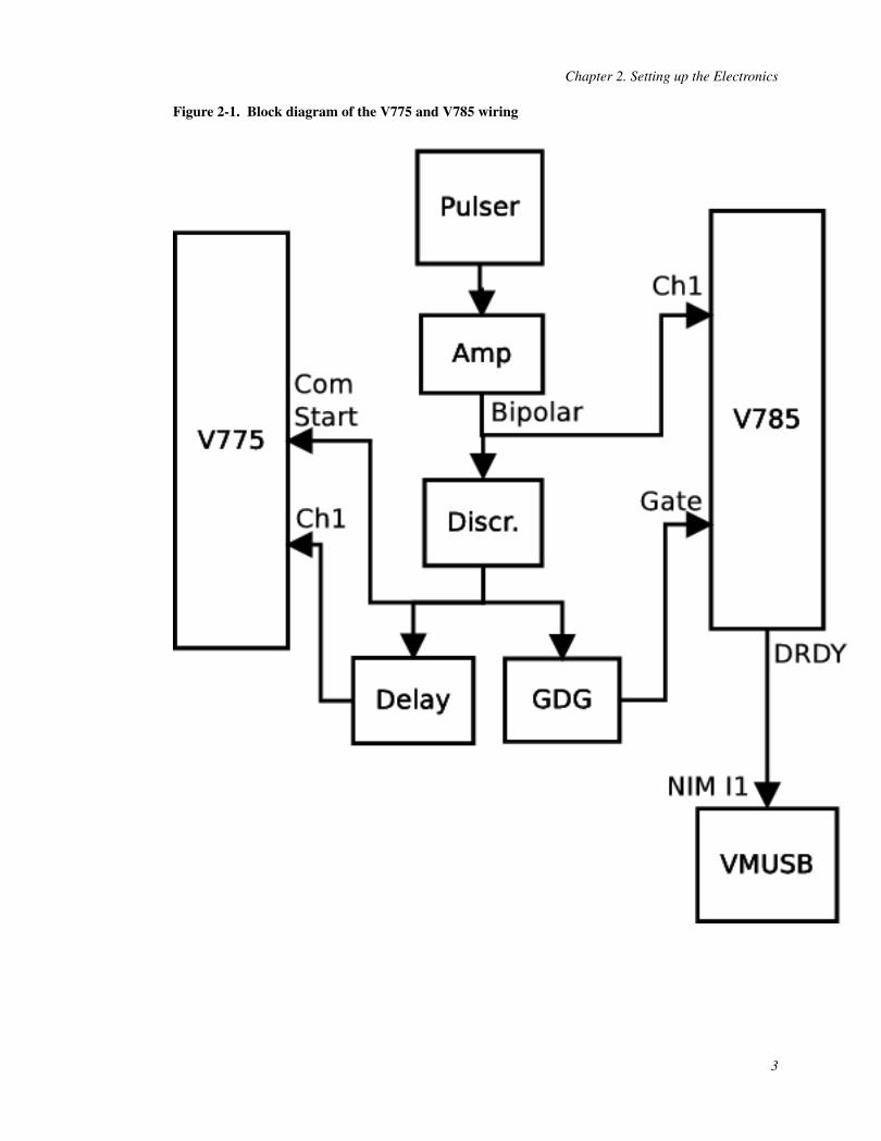
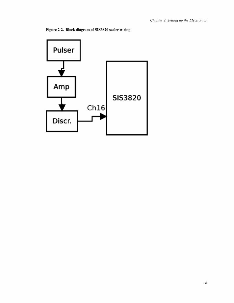
Rather than detail how to plug each cable into each module, th electronics diagram for the digitizers isprovided in Block diagram of the V775 and V785 wiring. Take note that this is a very basic circuit thatmakes no attempt to handle busy logic properly. It is designed specifically for generating some test data.Be aware also that there are some signal conversions not shown in the block diagram because their needdepends on the exact hardware being used. It is left up to the reader to determine whether a logic signalneeds to be converted from ECL to NIM or ECL to TTL or whatever between modules. A separatediagram is provided for the the scaler portion of the circuit at Block diagram of SIS3820 scaler wiring.
2
Chapter 2. Setting up the Electronics
Figure 2-1. Block diagram of the V775 and V785 wiring
3
Chapter 2. Setting up the Electronics
Figure 2-2. Block diagram of SIS3820 scaler wiring
4
Chapter 3. The Configuration Files
Because we are using hardware that is already supported by VMUSBReadout, the only tasks left are tocreate the daqconfig.tcl and ctlconfig.tcl scripts.
The ctlconfig.tcl script is the configuration file for the slow-controls subsystem. In this situation, itwill be an empty file because we are not attempting to use slow-controlled capabilities. We can quicklygenerate an empty file with the touch program at the command line. Here is how that works.
spdaqXX> touch ctlconfig.tcl
The next step is to build our daqconfig.tcl script. In that file, we will declare the V785, V775, andSIS3820 and add them to stacks. Doing so will cause them to be initialized at the beginning of each run,read out during triggers, and then transitioned back to an inactive mode at the end of each run. The V785and V775 will be read out using a chained block transfer for each event trigger, and the SIS3820 will beperiodically read using an internally generated trigger. We will therefore, need to define two separatestacks.
3.1. The event stack
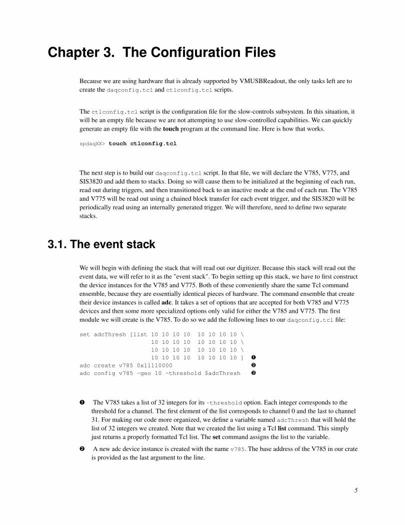
We will begin with defining the stack that will read out our digitizer. Because this stack will read out theevent data, we will refer to it as the "event stack". To begin setting up this stack, we have to first constructthe device instances for the V785 and V775. Both of these conveniently share the same Tcl commandensemble, because they are essentially identical pieces of hardware. The command ensemble that createtheir device instances is called adc. It takes a set of options that are accepted for both V785 and V775devices and then some more specialized options only valid for either the V785 and V775. The firstmodule we will create is the V785. To do so we add the following lines to our daqconfig.tcl file:
set adcThresh [list 10 10 10 10 10 10 10 10 \10 10 10 10 10 10 10 10 \10 10 10 10 10 10 10 10 \10 10 10 10 10 10 10 10 ] Ê
adc create v785 0x11110000 Ë
adc config v785 -geo 10 -threshold $adcThresh Ì
Ê The V785 takes a list of 32 integers for its -threshold option. Each integer corresponds to thethreshold for a channel. The first element of the list corresponds to channel 0 and the last to channel31. For making our code more organized, we define a variable named adcThresh that will hold thelist of 32 integers we created. Note that we created the list using a Tcl list command. This simplyjust returns a properly formatted Tcl list. The set command assigns the list to the variable.
Ë A new adc device instance is created with the name v785. The base address of the V785 in our crateis provided as the last argument to the line.
5
Chapter 3. The Configuration Files
Ì The device instance named v785 is configured. We specify via the -geo option which slot it livesin. This value will label the data outputted by the device during each readout cycle. It is importantthat this corresponds to the correct slot index the card is situated in. We also pass the list wofthresholds to the -thresholds option. The $ syntax dereferences the variable adcThresh andreturns the list that it refers to.
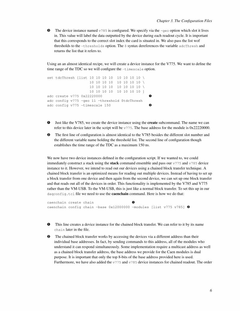
Using an an almost identical recipe, we will create a device instance for the V775. We want to define thetime range of the TDC so we will configure the -timescale option.
set tdcThresh [list 10 10 10 10 10 10 10 10 \10 10 10 10 10 10 10 10 \10 10 10 10 10 10 10 10 \10 10 10 10 10 10 10 10 ]
adc create v775 0x22220000 Ê
adc config v775 -geo 11 -threshold $tdcThreshadc config v775 -timescale 150 Ë
Ê Just like the V785, we create the device instance using the create subcommand. The name we canrefer to this device later in the script will be v775. The base address for the module is 0x22220000.
Ë The first line of configuration is almost identical to the V785 besides the different slot number andthe different variable name holding the threshold list. The second line of configuration thoughestablishes the time range of the TDC as a maximum 150 ns.
We now have two device instances defined in the configuration script. If we wanted to, we couldimmediately construct a stack using the stack command ensemble and pass our v775 and v785 deviceinstance to it. However, we intend to read out our devices using a chained block transfer technique. Achained block transfer is an optimized means for reading out multiple devices. Instead of having to set upa block transfer from one device and then again from the second device, we can set up one block transferand that reads out all of the devices in order. This functionality is implemented by the V785 and V775rather than the VM-USB. To the VM-USB, this is just like a normal block transfer. To set this up in ourdaqconfig.tcl file we need to use the caenchain command. Here is how we do that:
caenchain create chain Ê
caenchain config chain -base 0x12000000 -modules [list v775 v785] Ë
Ê This line creates a device instance for the chained block transfer. We can refer to it by its namechain later in the file.
Ë The chained block transfer works by accessing the devices via a different address than theirindividual base addresses. In fact, by sending commands to this address, all of the modules whounderstand it can respond simultaneously. Some implementation require a multicast address as wellas a chained block transfer address, the base address we provide for the Caen modules is dualpurpose. It is important that only the top 8-bits of the base address provided here is used.Furthermore, we have also added the v775 and v785 device instances for chained readout. The order
6

Chapter 3. The Configuration Files
of these modules should reflect the order in which they reside in the crate. The leftmost module inthe crate should be the first module in the list and the rightmost module should be the last in the list.
The caenchain extends the idea of a device instance, because it does not really reflect a piece ofhardware. Rather it is more of a virtual piece of hardware that handles the readout of multiple physicalpieces of hardware. With it created and configured, we are ready to create our stack and we will onlyregister the chain to the stack. Here is how that works
stack create evtStackstack config evtStack -modules [list chain] -trigger nim1 Ê
Ê A single element list containing chain is added to the stack. Because our v775 and v785 areregistered to the chain they will indirectly be read out. The -trigger option is passed a value ofnim1 to indicate that the stack will be triggered for execution whenever a logic pulse arrives at NIMinput 1.
3.2. The scaler stack
With the event stack already defined, we now turn to the definition of the stack responsible for readingout the SIS3820. Because this stack will deal with scaler data, it will be referred to as the scaler stack.The procedure for setting up the scaler stack is the same as for the event stack. First we create a deviceinstance for the SIS3820 and then we add it to a stack.
The Tcl command ensemble responsible for creating, configuring, and querying the state of an SIS3820is named sis3820. There are two options that can be configured for the device instances it creates and wewill only use the -base option. This will take the base address of the actual VME module. When this isadded to a stack, it will cause the VM-USB to read all 32 channels of the device it is associated with.Let’s add the following line to the bottom of our daqconfig.tcl file:
sis3820 create sclr 0x38000000
The scaler can then be added to a stack later by its name sclr. We will do that right now. Creating thestack for the scaler readout is done as normal using the stack. However, to define this a scaler stack thatgets periodically read out we need to specify different values for the options.
stack create sclrStackstack config sclrStack -modules [list sclr] -trigger scaler -period 2 Ê
Ê Purposing a stack for scaler readout is accomplished by passing scaler for the -triggerargument. Not only does this enable periodic execution of the stack, but it also labels the stack asindex 1. VMUSBReadout will treat the data read by this stack specifically as scaler data and turn it
7

Chapter 3. The Configuration Files
into ring items of type PERIODIC_SCALERS. The -period option was passed a value of 2 tospecify that we want the readout period to be 2 seconds.
The scaler stack is now complete.
8

Chapter 4. Running VMUSBReadout
There is a detailed overview of how to run VMUSBReadout in the comprehensive documentation ofNSCLDAQ. In this section we will assume that that has been read already and we will proceed bydefining a simple launcher script.
Unless you intend to keep your configuration scripts in the directory ~/config, you are required tospecify the location of the configuration scripts at launch. To avoid this, we will generate a short bashscript that will launch VMUSBReadout with the local configuration scripts. To do so, we create a scriptcalled govmusb that has the following contents.
#!/bin/sh Ê
$DAQBIN/VMUSBReadout --daqconfig=$PWD/daqconfig.tcl --ctlconfig=$PWD/ctlconfig.tcl Ë
Ë We assume that the DAQBIN environment variable has been specified by sourcing thedaqsetup.bash script. If you have not done this, you can source the script by doing (at the NSCL):
spdaqXX> unset DAQROOTspdaqXX> source /usr/opt/nscldaq/11.0/daqsetup.bash
The PWD environment is defined by default and stands for "present working directory." Note that thisimplies that the configuration scripts must live in the directory that the govmusb script is executedfrom.
To make the script executable, we have to change the permissions. Unless you want to prevent otherpeople from executing the launcher script you can let all users execute it. To do that we use the chmodcommand.
spdaqXX> chmod a+x govmusb
At this point you should be able to start up VMUSBReadout by executing the script. That is done bydoing:
spdaqXX> ./govmusb
At the prompt of VMUSBReadout, you can use the begin, end, pause, and resume commands to start,stop, pause, and resume runs.
9
Chapter 5. Understanding the Output
The output of the program can be inspected by attaching the dumper program to the ring buffer receivingthe data outputted from VMUSBReadout. Because we did not provide a different ring buffer at thecommand line when launching our program, the output will go to a ring buffer whose name is the sameas your username. This is actually the default value of the --source command line option of thedumper program. As a result we can attach the dumper with the following command from a differentterminal than the one running VMUSBReadout.
spdaqXX> dumper
If the run is active, you should see data printing to your screen. You can kill the dumper program bypressing CTL-C. A cleaner way to do this in the future is to provide dumper with a finite number of ringitems to process. For example, to process 10 ring items and then exit, one would enter:
spdaqXX> dumper --count=10
5.1. Event data
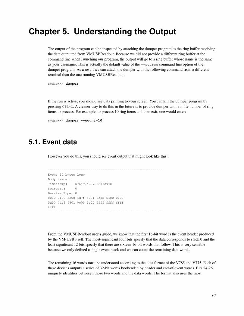
However you do this, you should see event output that might look like this:
-----------------------------------------------------------
Event 34 bytes long
Body Header:
Timestamp: 5764974207242862948
SourceID: 0
Barrier Type: 0
0010 0100 5200 4d7f 5001 0c08 5400 0100
5a00 4de4 5801 0c05 5c00 ffff ffff ffff
ffff
-----------------------------------------------------------
From the VMUSBReadout user’s guide, we know that the first 16-bit word is the event header producedby the VM-USB itself. The most-significant four bits specify that the data corresponds to stack 0 and theleast significant 12 bits specify that there are sixteen 16-bit words that follow. This is very sensiblebecause we only defined a single event stack and we can count the remaining data words.
The remaining 16 words must be understood according to the data format of the V785 and V775. Each ofthese devices outputs a series of 32-bit words bookended by header and end-of-event words. Bits 24-26uniquely identifies betweeen those two words and the data words. The format also uses the most
10

Chapter 5. Understanding the Output
significant five bits (bits 27-31) for the geographic address. The geographic address should be the samevalue we provided for the -geo option. For that reason, we expect that bits 27-31 of each 32-bit wordcan be used to identify whether the data originated from the V775 or the V785. Before we start parsingthe data further, let’s group the 16-bit words in the output into 32-bit words.
0x0010 Ê
0x52000100 Ë
0x50014d7f Ì
0x54000c08 Í
0x5a000100 Î
0x58014def Ï
0x5c000c05 Ð
0xffffffff0xffffffff Ñ
Ê VM-USB event header. This is just 16-bits.
Ë Header word for the V775 identified by bits 24-26 being the value 2. The most-significant 5 bit ofthis number is 10, which matches what was defined for the -geo option of the v775. Otherinformation encoded in this header are the crate index (bits 16-23) and the number of data wordsbefore the end-of-event word (bits 12-16). The header tells us that the module resides in crate 0 andthat there is a single data word that follows.
Ì This is the lone data word for the V775 identified by bits 24-26 being 0. Bits 27-31 still contain ageographic address of 10 as it should. Bits 16-20 identify the channel number for the data, bits 0-11identify the value and bits 12 and 13 are the underflow and overflow bits. We can use thisinformation to understand that digitized value did not underflow or overflow and resulted in thevalue 3455.
Í As we expect by header word of the V775, this is the end of event word. We know this for surebecause bits 24-26 store the value 4. Once again the bits 27-31 store the value 10 so the wordoriginated from the V775. The lower 24 bits store the event count, which converts to 3080 indecimal.
Î This word is the first word of the V785. It is a header word that corresponds to slot 11 and crate 0.There is one data word that follows prior to the end-of-event word.
Ï Here is the data for the V785. It corresponds to channel 1 and has a value f 3567.
Ð Here is the end-of-event word for the V785. It corresponds to event number 3077.
Ñ The 0xffffffff is what is returned by the devices when they complete their block transfer. There aretwo of these because each module is emitting BERR to signify they are done being read out.
In the above output, it is apparent that the event count of the V775 and V785 differ by 2 events, the V775having seen two more events than the V785. Such a condition is not terribly worrisome in this case,because the V775 is initialized prior to the V785. Because the initialization process is done before theVM-USB transitions to autonomous mode, the timing is controlled by the speed at which a VM-USB canexecute interactive commands and the speed at which the software operates. Such timing isindeterminate because the operation system scheduler plays a role. It should be expected that the time
11
Chapter 5. Understanding the Output
between clearing the V775 and V785 is on the order of milliseconds. If the rate is around 1 kHz, then itis possible that multiple triggers occur after the V775 has been cleared and the V785 clears.
5.2. Scaler data
If your most recent dump of the data using dumper did not include any scaler items in the output, youshould run the dumper again in such a way that excludes processing ring items of typePHYSICS_EVENT.
spdaqXX> $DAQBIN/dumper --count=5 --exclude=PHYSICS_EVENT
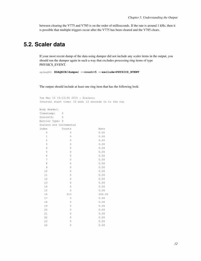
The output should include at least one ring item that has the following look:
Tue Mar 10 15:12:56 2015 : Scalers:
Interval start time: 10 end: 12 seconds in to the run
Body Header:
Timestamp: 0
SourceID: 0
Barrier Type: 0
Scalers are incremental
Index Counts Rate
0 0 0.00
1 0 0.00
2 0 0.00
3 0 0.00
4 0 0.00
5 0 0.00
6 0 0.00
7 0 0.00
8 0 0.00
9 0 0.00
10 0 0.00
11 0 0.00
12 0 0.00
13 0 0.00
14 0 0.00
15 0 0.00
16 513 256.50
17 0 0.00
18 0 0.00
19 0 0.00
20 0 0.00
21 0 0.00
22 0 0.00
23 0 0.00
24 0 0.00
12
Chapter 5. Understanding the Output
25 0 0.00
26 0 0.00
27 0 0.00
28 0 0.00
29 0 0.00
30 0 0.00
31 0 0.00
-----------------------------------------------------------
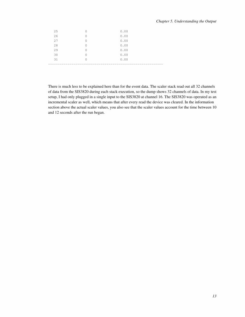
There is much less to be explained here than for the event data. The scaler stack read out all 32 channelsof data from the SIS3820 during each stack execution, so the dump shows 32 channels of data. In my testsetup, I had only plugged in a single input to the SIS3820 at channel 16. The SIS3820 was operated as anincremental scaler as well, which means that after every read the device was cleared. In the informationsection above the actual scaler values, you also see that the scaler values account for the time between 10and 12 seconds after the run began.
13

Chapter 6. Developing a Tailored SpecTcl
The dumper is not the most useful tool for understanding the data read out by the electronics. Instead weshould be using SpecTcl for that purpose, because it provides a much more straightforward and intuitiveway to inspect data. To use SpecTcl, we have to teach it how to retrieve the salient features of our dataand store them as tree parameters. Tree parameters are objects that behave as though the are plain olddouble values. What makes them special is that they are histogrammable entities. By unpacking raw datainto tree parameters, we can use SpecTcl to quickly define histograms from them.
An example of a simple SpecTcl implementation for unpacking a single V775 exists in conjunction withthe SBS Readout framework. To not repeat what has already been demonstrated, this will demonstratehow to develop a SpecTcl whose parsing utilities are separated from the SpecTcl framework. Inprinciple, the parsing class used here could be reused in other analysis framework like ROOT. It will alsodemonstrate a modern style of implementing C++ that leverages some newer C++11 features, like therange-based for loop.
6.1. Acquiring the Skeleton
There is a good deal of boilerplate code that goes into developing a tailored SpecTcl. To avoid rewritinga lot of that code, you can start from the "skeleton" implementation. This provides a fully functionalSpecTcl application that can be easily modified to support our specific needs. Getting the skeleton can beachieved by doing:
spdaqXX> mkdir MySpecTclspdaqXX> cd MySpecTclspdaqXX> cp /usr/opt/spectcl/3.4/Skel/* .
It does not matter all that much which specific version is used so long as it is at least version 3.4. Prior toversion 3.4 there was no support for the NSCLDAQ 11.0 data format. Because our data has beenacquired using an 11.0 version VMUSBReadout, it is therefore not possible to analyze it using an olderversion of SpecTcl.
6.2. Writing our Event Processor
SpecTcl has an analysis engine in it that handles all of the input/output type operations for the user. It cando so because it understands how to read raw data from an input stream and parse it into entities of agiven data format. Once it has determined the type of entity, it passes it to an analysis pipeline forprocessing. The details of the processing is very experiment specific and must be provided by theexperimenter. This is done by deriving a new class from the EventProcessor class and then registering itto the pipeline. Our derived EventProcessor will get passed the beginning of each physics event body forprocessing.
14

Chapter 6. Developing a Tailored SpecTcl
We intend to write an event processor that clearly separates the SpecTcl-like dependencies from theunpacking code. It will be named CRawUnpacker because it will operate on the raw data format. TheCRawUnpacker will be responsible for doing SpecTcl related things, like storing data into treeparameters, using a SpecTcl independent unpacking routine. The latter will be a class namedCRawADCUnpacker that will parse the data format produced by the V785 and V775 and store theresulting information in ParsedADCEvent objects.
It is good practice in C++ to declare the capabilities of our class in a header file and then implementthose capabilities in a source file. Doing so makes the code more flexible, reusable, and less bloated. Wewill follow this practice while implementing our SpecTcl, which means we have four files to create.
6.2.1. CRawUnpacker
Without further ado, let’s start by defining our CRawUnpacker header file, CRawUnpacker.h
#ifndef CRAWUNPACKER_H#define CRAWUNPACKER_H Ê
#include <config.h> Ë
#include "CRawADCUnpacker.h"#include <EventProcessor.h>#include <TreeParameter.h>#include <cstdint> Ì
#include <cstddef> Í
class CEvent;class CAnalyzer;class CBufferDecoder; Î
class CRawUnpacker : public CEventProcessor Ï
{private:CRawADCUnpacker m_unpacker;CTreeParameterArray m_values; Ð
public:CRawUnpacker();virtual ~CRawUnpacker();
virtual Bool_t operator()(const Address_t pEvent,CEvent& rEvent,CAnalyzer& rAnalyzer,CBufferDecoder& rDecoder); Ñ
private:Bool_t unpack(TranslatorPointer<std::uint32_t> begin,
std::size_t nLongWords); Ò
};
#endif
15
Chapter 6. Developing a Tailored SpecTcl
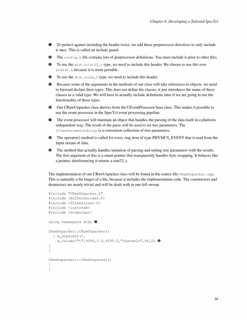
Ê To protect against including the header twice, we add these preprocessor directives to only includeit once. This is called an include guard.
Ë The config.h file contains lots of preprocessor definitions. You must include it prior to other files.
Ì To use the std::uint32_t type, we need to include this header. We choose to use this overstdint.h because it is more portable.
Í To use the std::size_t type, we need to include this header.
Î Because some of the arguments in the methods of our class will take references to objects, we needto forward declare their types. This does not define the classes, it just introduces the name of theseclasses as a valid type. We will have to actually include definitions later if we are going to use thefunctionality of these types.
Ï Our CRawUnpacker class derives from the CEventProcessor base class. This makes it possible touse the event processor in the SpecTcl event processing pipeline.
Ð The event processor will maintain an object that handles the parsing of the data itself in a platformindependent way. The result of the parse will be used to set tree parameters. TheCTreeParameterArray is a convenient collection of tree parameters.
Ñ The operator() method is called for every ring item of type PHYSICS_EVENT that is read from theinput stream of data.
Ò The method that actually handles initiation of parsing and setting tree parameters with the results.The first argument of this is a smart pointer that transparently handles byte swapping. It behaves likea pointer, dereferencing it returns a uint32_t.
The implementation of our CRawUnpacker class will be found in the source file CRawUnpacker.cpp.This is naturally a bit longer of a file, because it includes the implementation code. The constructors anddestructors are nearly trivial and will be dealt with in one fell swoop.
#include "CRawUnpacker.h"#include <BufferDecoder.h>#include <TCLAnalyzer.h>#include <iostream>#include <stdexcept>
using namespace std; Ê
CRawUnpacker::CRawUnpacker(): m_unpacker(),m_values("t",4096,0.0,4095.0,"channels",64,0) Ë
{}
CRawUnpacker::~CRawUnpacker(){}
16
Chapter 6. Developing a Tailored SpecTcl
Ê This brings uint32_t, size_t, and exception into scope. We avoid having to prefix these types withstd:: every time.
Ë The list of comma separated calls following the colon are called an initialize list. We use it toconstruct the data members. The second element of the list create a CTreeParameterArrayconsisting of 64 tree parameters, each having 4096 bins in a range of 0 to 4095. The names given tothese parameter are of the form "t.XX" where XX is the index, left-padded with zeroes.
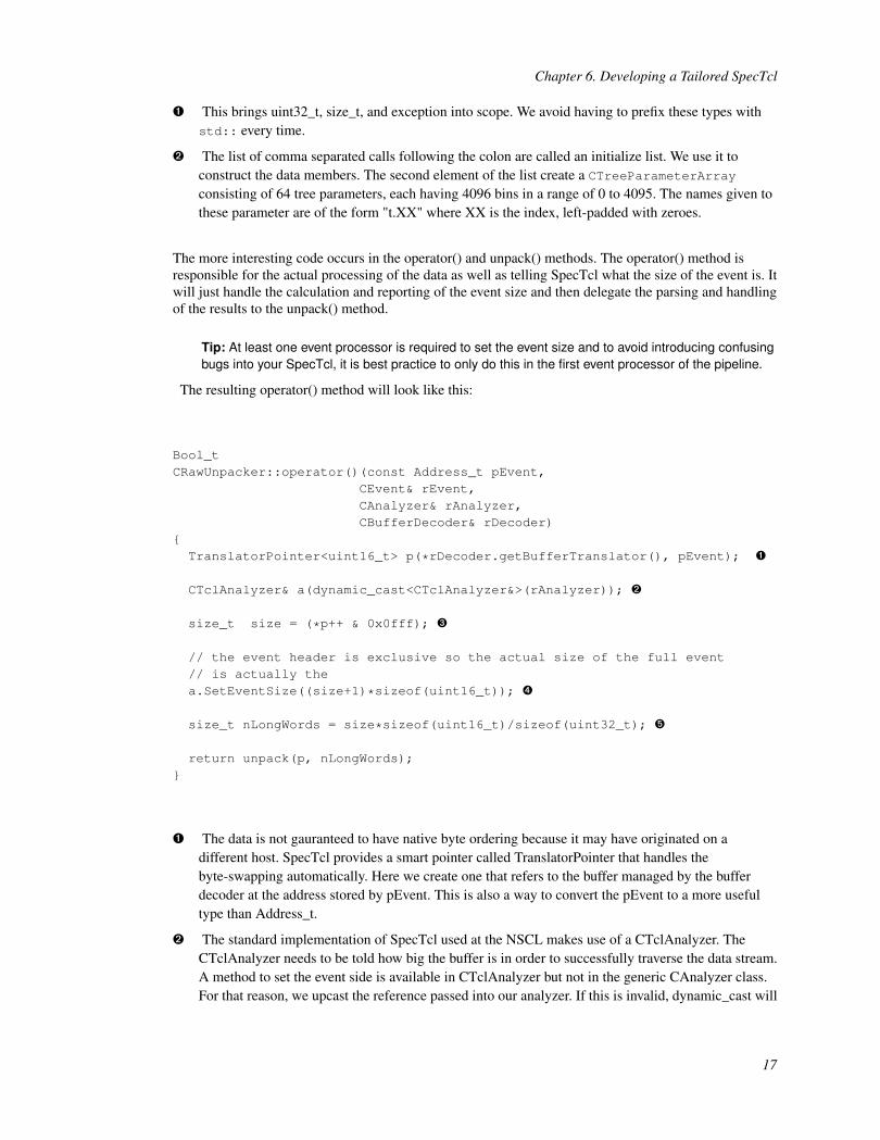
The more interesting code occurs in the operator() and unpack() methods. The operator() method isresponsible for the actual processing of the data as well as telling SpecTcl what the size of the event is. Itwill just handle the calculation and reporting of the event size and then delegate the parsing and handlingof the results to the unpack() method.
Tip: At least one event processor is required to set the event size and to avoid introducing confusingbugs into your SpecTcl, it is best practice to only do this in the first event processor of the pipeline.
The resulting operator() method will look like this:
Bool_tCRawUnpacker::operator()(const Address_t pEvent,
CEvent& rEvent,CAnalyzer& rAnalyzer,CBufferDecoder& rDecoder)
{TranslatorPointer<uint16_t> p(*rDecoder.getBufferTranslator(), pEvent); Ê
CTclAnalyzer& a(dynamic_cast<CTclAnalyzer&>(rAnalyzer)); Ë
size_t size = (*p++ & 0x0fff); Ì
// the event header is exclusive so the actual size of the full event// is actually thea.SetEventSize((size+1)*sizeof(uint16_t)); Í
size_t nLongWords = size*sizeof(uint16_t)/sizeof(uint32_t); Î
return unpack(p, nLongWords);}
Ê The data is not gauranteed to have native byte ordering because it may have originated on adifferent host. SpecTcl provides a smart pointer called TranslatorPointer that handles thebyte-swapping automatically. Here we create one that refers to the buffer managed by the bufferdecoder at the address stored by pEvent. This is also a way to convert the pEvent to a more usefultype than Address_t.
Ë The standard implementation of SpecTcl used at the NSCL makes use of a CTclAnalyzer. TheCTclAnalyzer needs to be told how big the buffer is in order to successfully traverse the data stream.A method to set the event side is available in CTclAnalyzer but not in the generic CAnalyzer class.For that reason, we upcast the reference passed into our analyzer. If this is invalid, dynamic_cast will
17

Chapter 6. Developing a Tailored SpecTcl
throw an exception of type std::bad_cast. We know it will succeed though because our analyzer is aCTclAnalyzer. Note that we cast to a reference to avoid copying the analyzer unnecessarily.
Ì The first 16-bit word of the VM-USB buffer contains the event header. The entire size of the bodyless 1 is contained in the lower 12-bits of this word. We use a bitwise-AND operator to extract thatnumber. Note that the *p++ effectively retrieved the value pointed and then incremented the pointerforward by 16-bits.
Í Here we pass the size of the event to the analyzer. The argument requires a size in units of bytesrather than 16-bit words. We convert by multiplying our number by the number of bytes in a 16-bitword (sizeof(uint16_t)). Note that we could have just multiplied by 2, but chose to dootherwise for readability sake.
Tip: Write for people to understand your code easier. Code is written once and read everytimethereafter.
Î The remainder of the buffer referred to by our pointer p is composed of 32-bit integers. We need toknow how many of these there are and will compute it. We are converting our size from units of16-bit integers to units of 32-bit integers.
The unpack() method implementation will look like this:
Bool_tCRawUnpacker::unpack(TranslatorPointer<uint32_t> begin,
size_t nLongWords){auto end = begin+nLongWords; Ê
try { Ë
vector<ParsedADCEvent> events = m_unpacker.parseAll(begin, end); Ì
int offset = 0;for (auto& event : events) { Í
offset = (event.s_geo-10)*32; Î
for (auto& chanData : event.s_data) { Ï
m_values[chanData.first+offset] = chanData.second;}
}} catch (exception& exc) { Ð
cout << "Parsing Failed! Reason=" << exc.what() << endl;return kfFALSE; Ñ
}
return kfTRUE; Ò
}
18
Chapter 6. Developing a Tailored SpecTcl
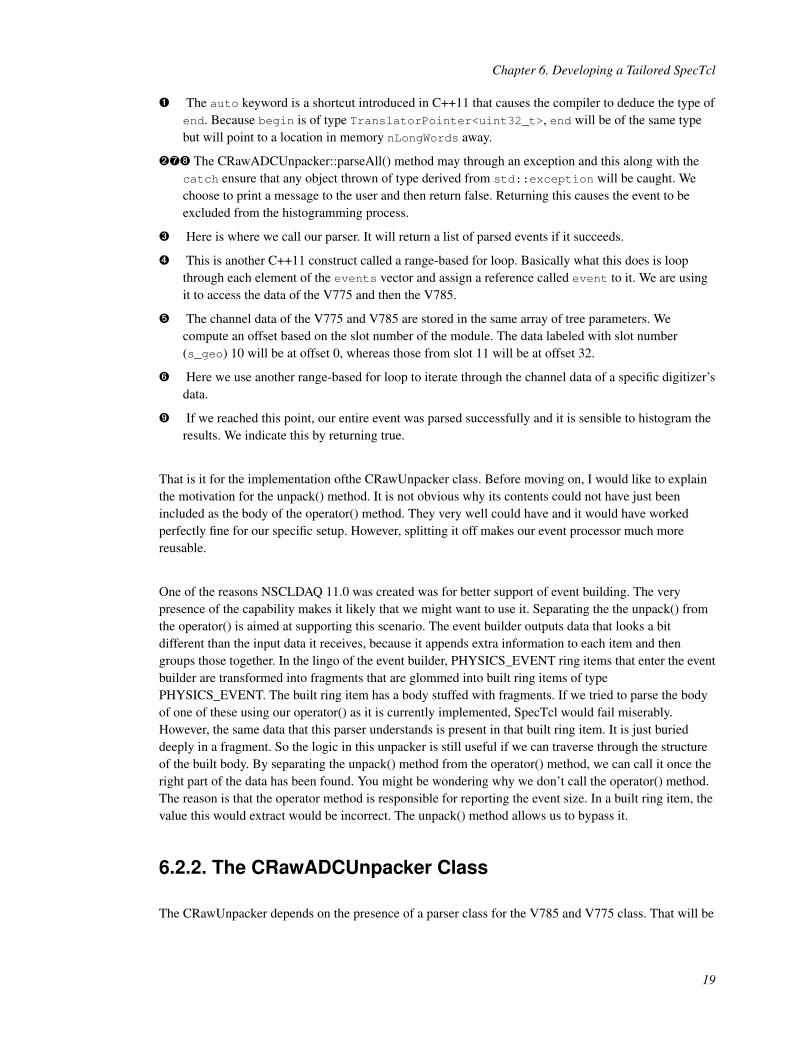
Ê The auto keyword is a shortcut introduced in C++11 that causes the compiler to deduce the type ofend. Because begin is of type TranslatorPointer<uint32_t>, end will be of the same typebut will point to a location in memory nLongWords away.
ËÐÑ The CRawADCUnpacker::parseAll() method may through an exception and this along with thecatch ensure that any object thrown of type derived from std::exception will be caught. Wechoose to print a message to the user and then return false. Returning this causes the event to beexcluded from the histogramming process.
Ì Here is where we call our parser. It will return a list of parsed events if it succeeds.
Í This is another C++11 construct called a range-based for loop. Basically what this does is loopthrough each element of the events vector and assign a reference called event to it. We are usingit to access the data of the V775 and then the V785.
Î The channel data of the V775 and V785 are stored in the same array of tree parameters. Wecompute an offset based on the slot number of the module. The data labeled with slot number(s_geo) 10 will be at offset 0, whereas those from slot 11 will be at offset 32.
Ï Here we use another range-based for loop to iterate through the channel data of a specific digitizer’sdata.
Ò If we reached this point, our entire event was parsed successfully and it is sensible to histogram theresults. We indicate this by returning true.
That is it for the implementation ofthe CRawUnpacker class. Before moving on, I would like to explainthe motivation for the unpack() method. It is not obvious why its contents could not have just beenincluded as the body of the operator() method. They very well could have and it would have workedperfectly fine for our specific setup. However, splitting it off makes our event processor much morereusable.
One of the reasons NSCLDAQ 11.0 was created was for better support of event building. The verypresence of the capability makes it likely that we might want to use it. Separating the the unpack() fromthe operator() is aimed at supporting this scenario. The event builder outputs data that looks a bitdifferent than the input data it receives, because it appends extra information to each item and thengroups those together. In the lingo of the event builder, PHYSICS_EVENT ring items that enter the eventbuilder are transformed into fragments that are glommed into built ring items of typePHYSICS_EVENT. The built ring item has a body stuffed with fragments. If we tried to parse the bodyof one of these using our operator() as it is currently implemented, SpecTcl would fail miserably.However, the same data that this parser understands is present in that built ring item. It is just burieddeeply in a fragment. So the logic in this unpacker is still useful if we can traverse through the structureof the built body. By separating the unpack() method from the operator() method, we can call it once theright part of the data has been found. You might be wondering why we don’t call the operator() method.The reason is that the operator method is responsible for reporting the event size. In a built ring item, thevalue this would extract would be incorrect. The unpack() method allows us to bypass it.
6.2.2. The CRawADCUnpacker Class
The CRawUnpacker depends on the presence of a parser class for the V785 and V775 class. That will be
19
Chapter 6. Developing a Tailored SpecTcl
implemented in the CRawADCUnpacker class. I had stated that I would do this in a frameworkindependent way. I will do so by showing a simpler example that depends on theTranslatorPointer<uint32_t> type for simplicity and then will explain how to generalize this afterwords.This will keep the example accessible to more people that don’t need their code 100% independent butwill also provide a clear path forward for those who do need it.
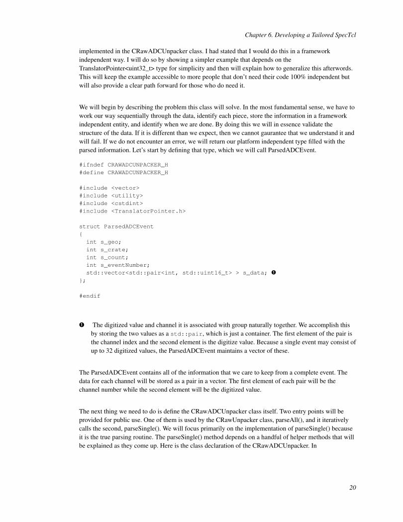
We will begin by describing the problem this class will solve. In the most fundamental sense, we have towork our way sequentially through the data, identify each piece, store the information in a frameworkindependent entity, and identify when we are done. By doing this we will in essence validate thestructure of the data. If it is different than we expect, then we cannot gaurantee that we understand it andwill fail. If we do not encounter an error, we will return our platform independent type filled with theparsed information. Let’s start by defining that type, which we will call ParsedADCEvent.
#ifndef CRAWADCUNPACKER_H#define CRAWADCUNPACKER_H
#include <vector>#include <utility>#include <cstdint>#include <TranslatorPointer.h>
struct ParsedADCEvent{int s_geo;int s_crate;int s_count;int s_eventNumber;std::vector<std::pair<int, std::uint16_t> > s_data; Ê
};
#endif
Ê The digitized value and channel it is associated with group naturally together. We accomplish thisby storing the two values as a std::pair, which is just a container. The first element of the pair isthe channel index and the second element is the digitize value. Because a single event may consist ofup to 32 digitized values, the ParsedADCEvent maintains a vector of these.
The ParsedADCEvent contains all of the information that we care to keep from a complete event. Thedata for each channel will be stored as a pair in a vector. The first element of each pair will be thechannel number while the second element will be the digitized value.
The next thing we need to do is define the CRawADCUnpacker class itself. Two entry points will beprovided for public use. One of them is used by the CRawUnpacker class, parseAll(), and it iterativelycalls the second, parseSingle(). We will focus primarily on the implementation of parseSingle() becauseit is the true parsing routine. The parseSingle() method depends on a handful of helper methods that willbe explained as they come up. Here is the class declaration of the CRawADCUnpacker. In
20
Chapter 6. Developing a Tailored SpecTcl
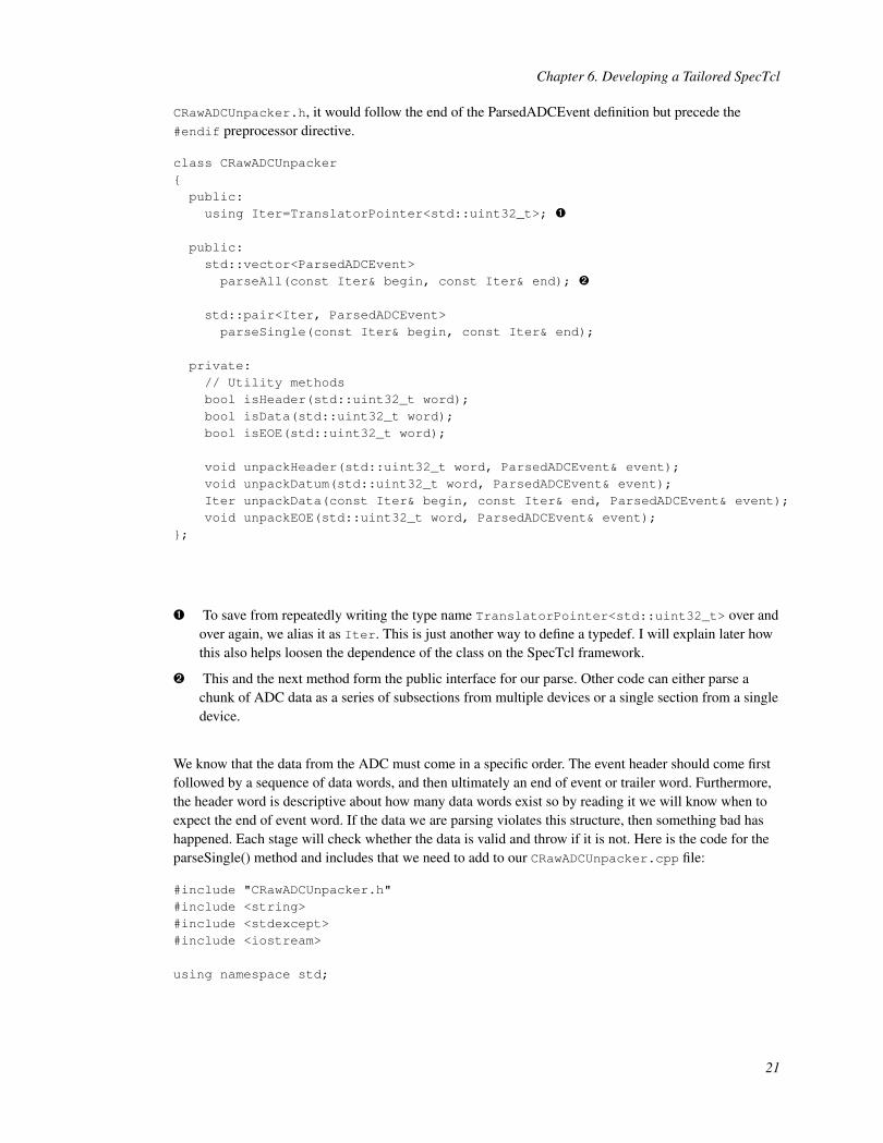
CRawADCUnpacker.h, it would follow the end of the ParsedADCEvent definition but precede the#endif preprocessor directive.
class CRawADCUnpacker{public:using Iter=TranslatorPointer<std::uint32_t>; Ê
public:std::vector<ParsedADCEvent>parseAll(const Iter& begin, const Iter& end); Ë
std::pair<Iter, ParsedADCEvent>parseSingle(const Iter& begin, const Iter& end);
private:// Utility methodsbool isHeader(std::uint32_t word);bool isData(std::uint32_t word);bool isEOE(std::uint32_t word);
void unpackHeader(std::uint32_t word, ParsedADCEvent& event);void unpackDatum(std::uint32_t word, ParsedADCEvent& event);Iter unpackData(const Iter& begin, const Iter& end, ParsedADCEvent& event);void unpackEOE(std::uint32_t word, ParsedADCEvent& event);
};
Ê To save from repeatedly writing the type name TranslatorPointer<std::uint32_t> over andover again, we alias it as Iter. This is just another way to define a typedef. I will explain later howthis also helps loosen the dependence of the class on the SpecTcl framework.
Ë This and the next method form the public interface for our parse. Other code can either parse achunk of ADC data as a series of subsections from multiple devices or a single section from a singledevice.
We know that the data from the ADC must come in a specific order. The event header should come firstfollowed by a sequence of data words, and then ultimately an end of event or trailer word. Furthermore,the header word is descriptive about how many data words exist so by reading it we will know when toexpect the end of event word. If the data we are parsing violates this structure, then something bad hashappened. Each stage will check whether the data is valid and throw if it is not. Here is the code for theparseSingle() method and includes that we need to add to our CRawADCUnpacker.cpp file:
#include "CRawADCUnpacker.h"#include <string>#include <stdexcept>#include <iostream>
using namespace std;
21
Chapter 6. Developing a Tailored SpecTcl
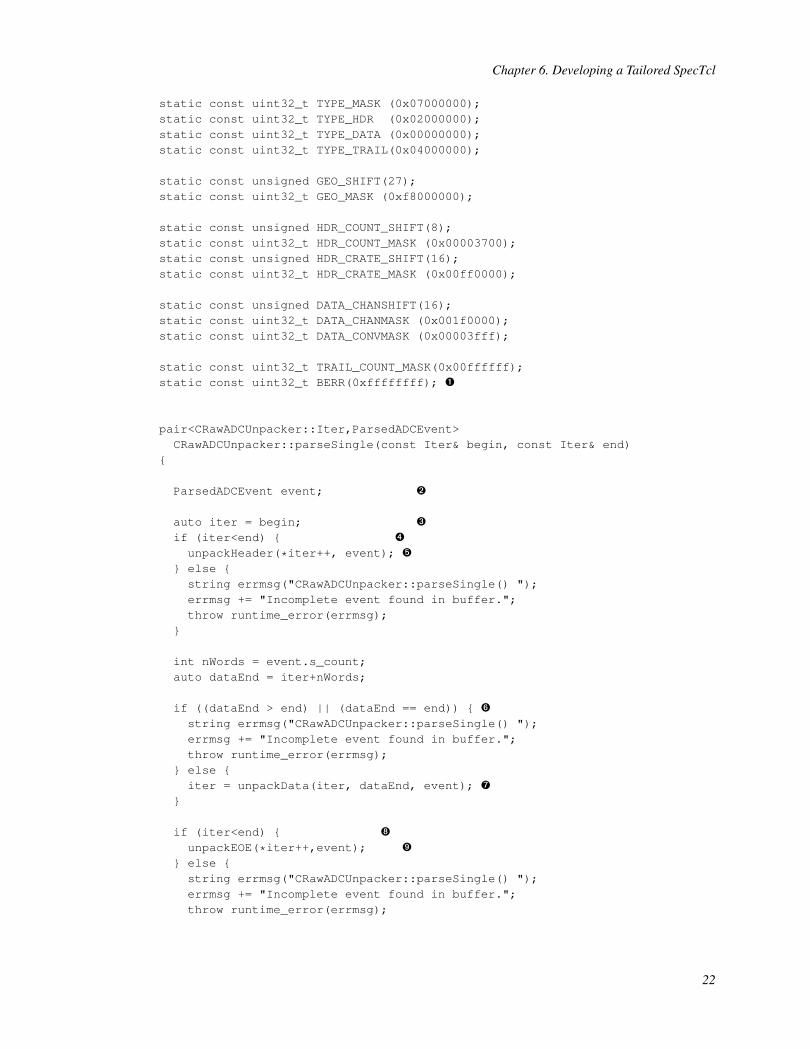
static const uint32_t TYPE_MASK (0x07000000);static const uint32_t TYPE_HDR (0x02000000);static const uint32_t TYPE_DATA (0x00000000);static const uint32_t TYPE_TRAIL(0x04000000);
static const unsigned GEO_SHIFT(27);static const uint32_t GEO_MASK (0xf8000000);
static const unsigned HDR_COUNT_SHIFT(8);static const uint32_t HDR_COUNT_MASK (0x00003700);static const unsigned HDR_CRATE_SHIFT(16);static const uint32_t HDR_CRATE_MASK (0x00ff0000);
static const unsigned DATA_CHANSHIFT(16);static const uint32_t DATA_CHANMASK (0x001f0000);static const uint32_t DATA_CONVMASK (0x00003fff);
static const uint32_t TRAIL_COUNT_MASK(0x00ffffff);static const uint32_t BERR(0xffffffff); Ê
pair<CRawADCUnpacker::Iter,ParsedADCEvent>CRawADCUnpacker::parseSingle(const Iter& begin, const Iter& end)
{
ParsedADCEvent event; Ë
auto iter = begin; Ì
if (iter<end) { Í
unpackHeader(*iter++, event); Î
} else {string errmsg("CRawADCUnpacker::parseSingle() ");errmsg += "Incomplete event found in buffer.";throw runtime_error(errmsg);
}
int nWords = event.s_count;auto dataEnd = iter+nWords;
if ((dataEnd > end) || (dataEnd == end)) { Ï
string errmsg("CRawADCUnpacker::parseSingle() ");errmsg += "Incomplete event found in buffer.";throw runtime_error(errmsg);
} else {iter = unpackData(iter, dataEnd, event); Ð
}
if (iter<end) { Ñ
unpackEOE(*iter++,event); Ò
} else {string errmsg("CRawADCUnpacker::parseSingle() ");errmsg += "Incomplete event found in buffer.";throw runtime_error(errmsg);
22
Chapter 6. Developing a Tailored SpecTcl
}
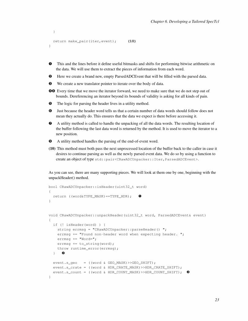
return make_pair(iter,event); (10)}
Ê This and the lines before it define useful bitmasks and shifts for performing bitwise arithmetic onthe data. We will use them to extract the pieces of information from each word.
Ë Here we create a brand new, empty ParsedADCEvent that will be filled with the parsed data.
Ì We create a new translator pointer to iterate over the body of data.
ÍÑ Every time that we move the iterator forward, we need to make sure that we do not step out ofbounds. Dereferencing an iterator beyond its bounds of validity is asking for all kinds of pain.
Î The logic for parsing the header lives in a utility method.
Ï Just because the header word tells us that a certain number of data words should follow does notmean they actually do. This ensures that the data we expect is there before accessing it.
Ð A utility method is called to handle the unpacking of all the data words. The resulting location ofthe buffer following the last data word is returned by the method. It is used to move the iterator to anew position.
Ò A utility method handles the parsing of the end-of-event word.
(10) This method must both pass the next unprocessed location of the buffer back to the caller in case itdesires to continue parsing as well as the newly parsed event data. We do so by using a function tocreate an object of type std::pair<CRawADCUnpacker::Iter,ParsedADCEvent>.
As you can see, there are many supporting pieces. We will look at them one by one, beginning with theunpackHeader() method.
bool CRawADCUnpacker::isHeader(uint32_t word){return ((word&TYPE_MASK)==TYPE_HDR); Ê
}
void CRawADCUnpacker::unpackHeader(uint32_t word, ParsedADCEvent& event){if (! isHeader(word) ) {string errmsg = "CRawADCUnpacker::parseHeader() ";errmsg += "Found non-header word when expecting header. ";errmsg += "Word=";errmsg += to_string(word);throw runtime_error(errmsg);
} Ë
event.s_geo = ((word & GEO_MASK)>>GEO_SHIFT);event.s_crate = ((word & HDR_CRATE_MASK)>>HDR_CRATE_SHIFT);event.s_count = ((word & HDR_COUNT_MASK)>>HDR_COUNT_SHIFT); Ì
}
23
Chapter 6. Developing a Tailored SpecTcl
Ê Here we use bitwise arithmetic to check that bits 24-26 are set to the value 2.
Ë If the word is not a header word, we failed to properly understand the data and parsing should stopimmediately. An exception is thrown.
Ì Using bitwise arithmetic again, we extract the geo value (slot number), crate number, and numberof data words to follow. These are all stored to the event we are filling.
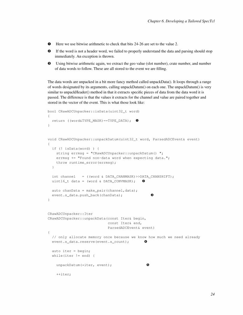
The data words are unpacked in a bit more fancy method called unpackData(). It loops through a rangeof words designated by its arguments, calling unpackDatum() on each one. The unpackDatum() is verysimilar to unpackHeader() method in that it extracts specific pieces of data from the data word it ispassed. The difference is that the values it extracts for the channel and value are paired together andstored in the vector of the event. This is what those look like:
bool CRawADCUnpacker::isData(uint32_t word){return ((word&TYPE_MASK)==TYPE_DATA); Ê
}
void CRawADCUnpacker::unpackDatum(uint32_t word, ParsedADCEvent& event){if (! isData(word) ) {string errmsg = "CRawADCUnpacker::unpackDatum() ";errmsg += "Found non-data word when expecting data.";throw runtime_error(errmsg);
}
int channel = ((word & DATA_CHANMASK)>>DATA_CHANSHIFT);uint16_t data = (word & DATA_CONVMASK); Ë
auto chanData = make_pair(channel,data);event.s_data.push_back(chanData); Ì
}
CRawADCUnpacker::IterCRawADCUnpacker::unpackData(const Iter& begin,
const Iter& end,ParsedADCEvent& event)
{// only allocate memory once because we know how much we need alreadyevent.s_data.reserve(event.s_count); Í
auto iter = begin;while(iter != end) {
unpackDatum(*iter, event); Î
++iter;
24
Chapter 6. Developing a Tailored SpecTcl
}
return iter; Ï
}
Ê We check that bits 24-26 store the value 0.
Ë Using bit-wise arithmetic we extract the channel and value.
Ì The channel and value are paired together and then added to the end of the vector.
Í Initially the vector that will store the channel data has zero size. Every time that a new element isadded we will push it onto the back of the vector. By default, this will likely cause the vector’smemory buffer to be reallocated everytime we add an element, which is costly. Because we alreadyknow the final size, we can allocate the total memory once using the vector<>::reserve method.
Î To parse all of the data words, we just iterate through the range that has been passed in asparameters. Each word is unpacked by a call to the unpackDatum() method. If the word is not a dataword, an exception is thrown.
Ï The location of the next unparsed word in the buffer is returned to the caller.
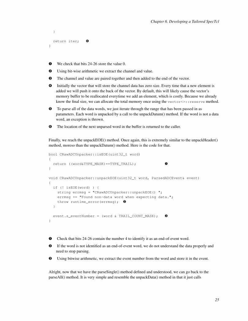
Finally, we reach the unpackEOE() method. Once again, this is extremely similar to the unpackHeader()method, moreso than the unpackDatum() method. Here is the code for that.
bool CRawADCUnpacker::isEOE(uint32_t word){return ((word&TYPE_MASK)==TYPE_TRAIL); Ê
}
void CRawADCUnpacker::unpackEOE(uint32_t word, ParsedADCEvent& event){if (! isEOE(word) ) {string errmsg = "CRawADCUnpacker::unpackEOE() ";errmsg += "Found non-data word when expecting data.";throw runtime_error(errmsg); Ë
}
event.s_eventNumber = (word & TRAIL_COUNT_MASK); Ì
}
Ê Check that bits 24-26 contain the number 4 to identify it as an end-of-event word.
Ë If the word is not identified as an end-of-event word, we do not understand the data properly andneed to stop parsing.
Ì Using bitwise arithmetic, we extract the event number from the word and store it in the event.
Alright, now that we have the parseSingle() method defined and understood, we can go back to theparseAll() method. It is very simple and resemble the unpackData() method in that it just calls
25
Chapter 6. Developing a Tailored SpecTcl
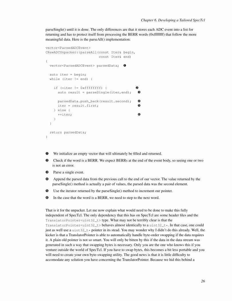
parseSingle() until it is done. The only differences are that it stores each ADC event into a list forreturning and has to protect itself from processing the BERR words (0xffffffff) that follow the moremeaningful data. Here is the parseAll() implementation:
vector<ParsedADCEvent>CRawADCUnpacker::parseAll(const Iter& begin,
const Iter& end){vector<ParsedADCEvent> parsedData; Ê
auto iter = begin;while (iter != end) {
if (*iter != 0xffffffff) { Ë
auto result = parseSingle(iter,end); Ì
parsedData.push_back(result.second); Í
iter = result.first; Î
} else {++iter; Ï
}}
return parsedData;}
Ê We initialize an empty vector that will ultimately be filled and returned.
Ë Check if the word is a BERR. We expect BERRs at the end of the event body, so seeing one or twois not an error.
Ì Parse a single event.
Í Append the parsed data from the previous call to the end of our vector. The value returned by theparseSingle() method is actually a pair of values, the parsed data was the second element.
Î Use the iterator returned by the parseSingle() method to increment our pointer.
Ï In the case that the word is a BERR, we need to step to the next word.
That is it for the unpacker. Let me now explain what would need to be done to make this fullyindependent of SpecTcl. The only dependency that this has on SpecTcl are some header files and theTranslatorPointer<uint32_t> type. What may not be terribly clear is that theTranslatorPointer<uint32_t> behaves almost identically to a uint32_t*. In that case, one couldjust as well use a uint32_t* pointer in its stead. You may wonder why I didn’t do this already. Well, thekicker is that a TranslatorPointer is able to automatically handle byte-order swapping if the data requiresit. A plain old pointer is not so smart. You will only be bitten by this if the data in the data stream wasgenerated in such a way that swapping bytes is necessary. Only you are the one who knows this if youventure outside the world of SpecTcl. If you have to swap bytes, this becomes a bit less portable and youwill need to create your own byte-swapping utility. The good news is that it is little difficulty toaccomodate any solution you have concerning the TranslatorPointer. Because we hid this behind a
26

Chapter 6. Developing a Tailored SpecTcl
typedef, we only need to change the Iter alias to be a different type. Arguably the more general solutionwould be to transform the class into a template itself where the Iter is the template parameter. Doing sorequires more changes to the code but would not have to be recompiled whenever you wanted to changethe type. The most important thing here is that these changes never require a change to the actualimplementation code. The only requirement is that whatever you choose to use for the iteratorimplements the operators used. Any random access iterator will fulfill that requirement, but you need notgo so far to implement all requirements of a random access iterator. As for the included headers, you canuse preprocessor conditionals for this. If you are building with SpecTcl, then you will need the properheaders, otherwise, you should not include them.
6.3. Setting up the Event Processing Pipeline
The MySpecTclApp.cpp contains the code the defines the event processing pipeline. We need to add aninstance of the CRawUnpacker class to it in order for our code to execute. You will notice that inMySpecTclApp.cpp there are already a handful of predefined event processors that are registered to thepipeline. We need to make the following changes. First, find the following two line:
static CFixedEventUnpacker Stage1;static CAddFirst2 Stage2;
You should replace the two lines with a single line:
static CRawUnpacker gRawStage;
You will also need to add the following line to the list of includes at the top of the file.
#include "CRawUnpacker.h"
The next thing you need to do is find the method calledCMySpecTclApp::CreateAnalysisPipeline(). In it your should replace the entire body to looklike:
voidCMySpecTclApp::CreateAnalysisPipeline(CAnalyzer& rAnalyzer){RegisterEventProcessor(gRawStage, "Raw");
}
With that, SpecTcl will pass every ring item of type PHYSICS_EVENT to our event processor.
27
Chapter 6. Developing a Tailored SpecTcl
Typically, after the first event processor there might be subsequent processors that compute the values ofother tree parameters from the raw value extracted by the first. A good example of this is computed acalibrated value from the raw value. It is common and recommended practice to write the subsequentevent processors in such a way that they depend only on the tree parameters that were assigned values inthe first processor. There are many ways to accomplish this. One method would be to separate the treeparameters from the CRawUnpacker class and define a structure that provides other processors access tothem. Another method might be to define them as a static member of the CRawUnpacker class. These arejust two ways that pop into my head, but you can solve the problem however best makes sense to you.Remember that SpecTcl is a software framework much like other analysis frameworks, e.g. ROOT. Ifyou can code it in C++ and work within the constraints of the SpecTcl framework, nothing stops youfrom doing that.
6.4. Building SpecTcl
Because we have added two extra classes to the SpecTcl application, we need to ensure that they areadded to the build. That is easily done by modifying the OBJECTS variable. You should edit yourMakefile to look like this:
OBJECTS=MySpecTclApp.o CRawUnpacker.o CRawADCUnpacker.o
Furthermore, because we have made use of a handful of C++11 features, we need to ensure that thecompiler operates in the C++11 mode. This is accomplished with the -std=c++11 flag. You should addit to the USERCXXFLAGS variable. In the end, that line will resemble this:
USERCXXFLAGS= -std=c++11
We can now compile our program. You should see this succeed with no errors. Compilation is initiatedby the make command.
spdaqXX> make
28
Chapter 7. The VMUSBSpecTcl Alternative
Now that we have a fully implemented tailored SpecTcl, I will likely upset you by telling you that aprogram called VMUSBSpecTcl is available with SpecTcl distributions newer than 3.3-009. Thisprogram provides a mechanism to build a parser for your VMUSBReadout data just by reading thedaqconfig.tcl file. This is a very limited program that can parse only a subset of the modulessupported by VMUSBReadout. It is not intended to be used for parsing actual experiments. However, itis perfect for small setups. You can read more about it by pointing a browser at/usr/opt/spectcl/3.4/share/vmusb/index.html
spdaqXX> firefox /usr/opt/spectcl/3.4/share/vmusb/index.html
That documentation will teach you how to set up the program. However, the next section will still beuseful to teach you how to create histograms, so don’t stop reading here.
29

Chapter 8. Using SpecTcl
To start using SpecTcl, you need to define at least one histogram and then attach to a data source. Let’sstart by launch SpecTcl. In the directory that you have copied the skeleton into, there should be aSpecTclRC.tcl file. This is a Tcl script that gets sourced upon start up. We will not dwell on the detailsof it here, but you need to make sure it is present. In that directory launch SpecTcl:
spdaqXX> ./SpecTcl
SpecTcl can take a while to start up so give it 5 to 10 seconds to complete its initialization routines. Onceit is up and running, you should have four new windows open that correspond to Xamine, the TreeGui,the SpecTcl control panel, and tkcon. The definition of histograms is accomplished in the TreeGui.Without exploring all of the options for histograms, a one dimensions histogram is created by selecting atree parameter to associate with it and also a name to refer to the histogram by. Let’s create our first 1-dhistogram:
1. In the middle of the window on the left, there is a text entry for a tree parameter name. We know ourtree parameters are named "t.XX" so we can choose an index and write the name. Here I choose"t.01". In the following figure, I have highlighted the text entry in red.
If you do not know the name of your tree parameter, you can use the "Parameter" button above thetext entry to select one.
30
Chapter 8. Using SpecTcl
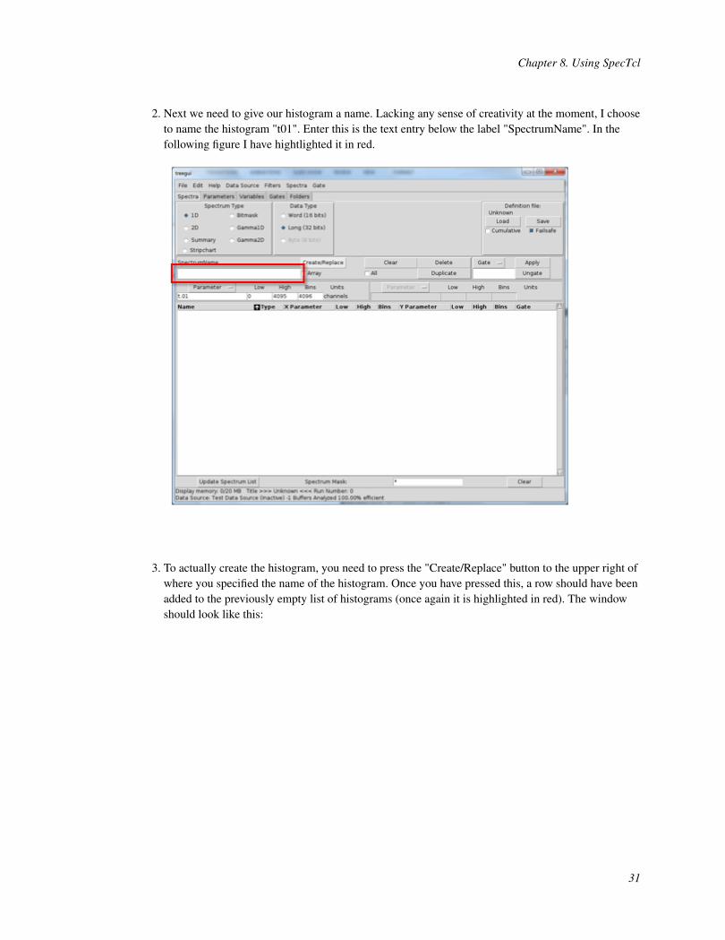
2. Next we need to give our histogram a name. Lacking any sense of creativity at the moment, I chooseto name the histogram "t01". Enter this is the text entry below the label "SpectrumName". In thefollowing figure I have hightlighted it in red.
3. To actually create the histogram, you need to press the "Create/Replace" button to the upper right ofwhere you specified the name of the histogram. Once you have pressed this, a row should have beenadded to the previously empty list of histograms (once again it is highlighted in red). The windowshould look like this:
31
Chapter 8. Using SpecTcl
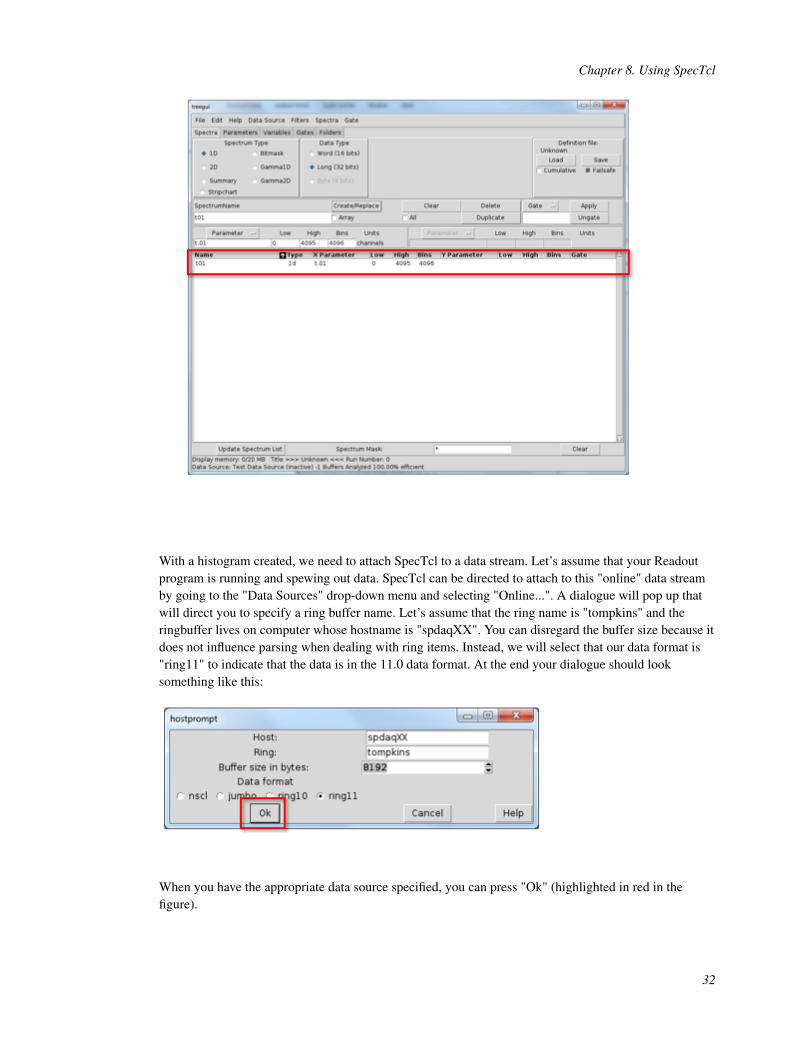
With a histogram created, we need to attach SpecTcl to a data stream. Let’s assume that your Readoutprogram is running and spewing out data. SpecTcl can be directed to attach to this "online" data streamby going to the "Data Sources" drop-down menu and selecting "Online...". A dialogue will pop up thatwill direct you to specify a ring buffer name. Let’s assume that the ring name is "tompkins" and theringbuffer lives on computer whose hostname is "spdaqXX". You can disregard the buffer size because itdoes not influence parsing when dealing with ring items. Instead, we will select that our data format is"ring11" to indicate that the data is in the 11.0 data format. At the end your dialogue should looksomething like this:
When you have the appropriate data source specified, you can press "Ok" (highlighted in red in thefigure).
32

Chapter 8. Using SpecTcl
The status bar at the bottom of the tree gui should show that it is connect and processing events at thispoint. The next thing to do is move to the Xamine window and display our histogram. The bottom leftcorner of the Xamine window has a button labeled "Display+".
Press the "Display+" button and select a histogram to display. In my case, there is only a singlehistogram named "t01" to choose from. Click on the histogram name and press "Okay". The histogramshould now be visible and Xamine should look something like this:
33

Chapter 8. Using SpecTcl
You can press "Update All" to see the histogram grow in counts from here on out. With a singlehistogram created, you should be able to figure out how to create other 1-d histograms and even 2-dhistograms. The process is very similar. Be aware, that you need to create a histogram prior to attachingto a data source for it to receive any data.
34
Chapter 9. Conclusion
The contents of the tutorial touched on the tip of the iceberg concerning how to run an experiment usingNSCLDAQ. However, at this point, you should be well acquainted with the principles associated withVMUSBReadout and SpecTcl. More complicated systems simply require longer configuration files andmore detailed SpecTcl event processors.
35