a review of the latest developments in electrodes for ... review of developments in... · a fuel...
TRANSCRIPT

A review of the latest developments in electrodes for unitised regenerative polymer electrolyte fuel cells
J Pettersson B Ramsey and D HarrisonSchool of Engineering amp Design Brunel University Uxbridge Middlesex UB8 3PH UK
AbstractThe design of electrodes for unitised regenerative polymer electrolyte fuel cells (URFC) requires a delicate balancing of transport media Gas transport electrons and protons must be carefully optimised to provide efficient transport to and from the electrochemical reaction sites This review is a survey of recent literature with the objective to identify common components and design and assembly methods for URFC electrodes focusing primarily on the development of a better performing bifunctional electrocatalyst for the oxygen reduction and water oxidation Advances in unitised regenerative fuel cells research have yielded better performing oxygen electrocatalysts capable of improving energy efficiency with longer endurance and less performance degradation over time Fuel cells using these electrocatalyst have a possible future as a source of energy
Keywords Regenerative fuel cell Electrocatalyst Water electrolysis Thin-film electrodes Gas diffusion layer
1 IntroductionToday energy consumers on earth are heavily dependent on air polluting fossil fuels and with the present production rate our energy reservoirs could be emptied in less than a couple of hundred years The environmental situation looks even more critical if we consider a scenario where coal becomes the main resource and the energy consumption per capita in heavily populated developing countries continues to increase at the same rate as today So far around two billion people in the world do not have access to electricity [1] Providing such a number of people with electricity will have a major effect on the environment if fossil fuels are used
The frightening situation described above could to some extent be avoided by providing remote areas with renewable energy technologies such as biomass solar heat photovoltaics and wind turbines However solar energy and wind energy are intermittent resources ie the energy availability changes from hour to hour from day to night and from season to season This uncertainty in energy supply could however be eliminated by connecting a local energy storage system to the production unit To some extent conventional batteries have so far been used for this purpose but the storage cost increases significantly with storage capacity Some scientists believe that a promising alternative to batteries would be energy storage by hydrogen which is a pollution-free flexible energy carrier see Fig 1
Fig 1 Schematic of energy conversions with hydrogen as a possible long-term storage
A possible storage system for the conversion of electrical energy consists of a hydrogen production unit a storage medium and a unit which converts the chemical energy stored in the hydrogen back
to electricity (with help from oxygen or air) Such a system is preferably connected to a renewable energy source such as solar or wind which provides an electrolyser cell with enough energy to split water into hydrogen and oxygen The gases are either stored or used directly in a fuel cell In a fuel cell the opposite reaction to electrolysis takes place ie hydrogen and oxygen (or air) are recombined to produce electricity heat and water A system like this with both an electrolyser and a fuel cell is called a regenerative fuel cell (RFC) [2] and [3] A much smaller and compact unit see Fig 2 is the unitised regenerative fuel cell (URFC) where the electrolyser and fuel cell are combined into one unit and only one of the two modes can be operated at one time Usually the electrolyser is operated first to produce the hydrogen and oxygen which are stored and later supplied back to the same unit when desired which then operates as a fuel cell Thus a URFC is a simpler and more compact system than the RFC and it uses only one electrochemical cell [3] [4] [5] [6] [7] and [8]
Fig 2 Concept of (a) regenerative fuel cell (RFC) and (b) unitised regenerative fuel cell (URFC)
Typical storage media for hydrogen and oxygen gases are either under conventional pressure vessels or in metal hydrides Metal and liquid hydrides such as FeTi [9] and methanol or cyclohexane [10] respectively and adsorbed carbon compounds [9] and [10] are the principal methods of bonding hydrogen chemically They are the safest methods of storage as no hydrogen will be released in the event of an accident but they are bulky and heavy and additional energy is also needed to release the stored hydrogen again One of the most recent and exciting advances has been the announcement of carbon nanofibre technology [9] and [11] This may have the capacity to store up to 70 of hydrogen by weight [12] and [13] and would be a promising storage device to be used in conjunction with a lightweight URFC system
Another promising technology is self-pressurising electrolysers [14] which are used to supply compressed hydrogen and oxygen This process could reduce or eliminate conventional pressure tanks all together depending on what pressure level is needed This would be a more efficient system and a simpler and less expensive solution
The key technology in the development of the PEM URFC is the fabrication of active electrocatalysts for both the oxygen reduction and the water oxidation at the oxygen electrode The bifunctional electrocatalyst must also be resistant to anodic corrosion during the water electrolysis reaction Several studies have reported on noble metals and metal oxides including PtIrO2 and PtRuO2 as possible catalysts for the URFC oxygen electrode [4] [6] [15] [16] and [17]
Recently there has been added interest in the solid oxide regenerative fuel cell (SORFC) and its higher potential for energy storage efficiency compared to lower temperature systems Solid oxide electrolysers show a much lower overpotential than for example the PEM electrolyser at standard pressure and 850 degC compared to 80 degC [18] The higher operating temperature of the SORFC makes it ideal as a candidate for on-grid and off-grid distributed energy storage and possibly as energy storage devices for airships and submarines with its thermal energy produced It would not be ideal on any smaller scale were ambient temperature and pressure would be the main requirements such a system would be more suited to use the polymer electrolyte membrane URFC
11 Polymer electrolyte membrane
The solid membrane in unitised regenerative polymer electrolyte membrane (PEM) fuel cells is usually a perflourosulfonic acid polymer [19] This is a polytetrafluoroethylene (PTFE trade name Teflon) chain with side chains terminating in an SO3H group It is the hydrogen on this sulfonate group that dissociates from the polymer when wet and appears as protons in the solution polymer acids have the advantage that the anion (ndashSO3
minus tail) is fixed in the electrolyte rather than dissolved
One common PEM is Nafion a polymer developed by DuPont in the 1960s for use as a separator in the chlor-alkali industry and now used for other industrial electrochemical purposes [20] Polymer electrolyte membranes can be made extremely thin less than 50 μm making for densely packed stacks and consequently high power densities The thinness of the PEM also means high conductance and low ohmic resistance losses
Another proton exchange membrane the Dow membrane is also a promising candidate for the URFC but testing thereof has not been found in the literature
12 Catalyst layer
The catalyst layer in a unitised regenerative fuel cell is in direct contact with the membrane and the gas diffusion layer see Fig 3 This layer is either applied directly to the membrane or to the gas diffusion layer with the aim to get the catalyst particles as close as possible to the polymer electrolyte membrane Catalyst layers for URFCs have always been an important part of the development of efficient regenerative cells Historically Pt black has been used as the sole catalyst but later research has recognised several other suitable catalysts including iridium (Ir) ruthenium (Ru) and rhodium (Rh) [21] [22] and [23] Research has also been concentrated on lowering the high Pt content in URFC catalyst layers (typically 3ndash7 mg cmminus2) and later research has shown that catalyst loading as low as 04 mg cmminus2 is possible with the help of a supported bifunctional catalyst [5]
Fig 3 Scanning electron micrograph (SEM) of a cross-section of an electrode assembly [24]
13 Electrode manufacture
URFC electrode designs have typically used proven and tested methods to produce the electrodendashmembranendashelectrode interface Most widely used is the transfer print technique followed by hot press (andor roll press) of the design for more intimate contact of active materials [4] [5] [6] [8] and [22] Application techniques like spraying painting and casting are also used Other emerging promising methods are chemical reduction [7] electrodeposition and sputter deposition but these will not be discussed here in any depth
14 Gas diffusion layer
The porous gas diffusion layer (GDL) in URFCs ensures an even distribution and removal of reactants and products from the electrode area It is also acting as the electrical conductor ensuring transport of electrons to and from the catalyst layer The GDL is also an important factor in the water management of the cell balancing between the different properties of the fuel cell and the water electrolyser It also plays a vital role in the hydration of the polymer electrolyte membrane
2 URFC membranendashelectrode assemblies (MEAs)
There are two problems encountered when designing electrode structures for URFC systems For PEM fuel cells highly hydrophobitised carbon paper or carbon cloth is usually adopted as the gas diffusion layer or electrode materials however they cannot be used as the GDL of a URFC for the following two reasons firstly the carbon materials tend to corrode at high potentials on the oxygen electrode side during the water electrolysis operation secondly GDLs have to achieve an appropriate balance between the hydrophobic and hydrophilic properties for both the fuel cell and water electrolysis operations as shown in Fig 4 The fuel cell operation requires that the oxygen GDL have a hydrophobic property to prevent water flooding on the other hand water electrolysis requires that the GDL have a hydrophilic property to supply water to the oxygen electrode Several methods have been demonstrated to overcome these problems by using specially designed electrodes with complex multi-layer structures or membranes with internal fluid passages [4] [5] [25] and [26] However while these methods overcome some of the basic problems neither of these approaches leads to a cell (stack) with adequate performance for use in applications
Fig 4 Schematic of a URFC with reactions (a) PEM electrolyser and (b) PEM fuel cell
In a typical design of a URFC each electrode is always in contact with the same gas hydrogen or oxygen and the electrical polarisation of the cell (or stack) is reversed when the system changes function see Fig 4 Therefore if the unit is operating as an electrolyser the oxygen electrode is the anode and the hydrogen electrode is the cathode If the unit is operating as a fuel cell the oxygen electrode is the cathode and the hydrogen electrode is the anode It is therefore important when designing electrodes for URFCs that they are both designed so that they do not degrade when operated in an oxidising environment (Fig 5)
Fig 5 Membranendashelectrode assembly of typical PEM URFC
21 URFC hydrogen electrode
There have been many studies on suitable electrocatalysts for URFCs however the majority of them focus on the development of a suitable catalyst for the oxygen electrode and only briefly
discuss the formation of the hydrogen electrode [4] [5] [6] [7] and [16] This is more than likely due to the favourable kinetics of hydrogen on platinum on the hydrogen electrode and hydrogen evolution is known to perform best with platinum as the catalyst material [27] High current densities are realised at low overpotentials see typical currentndashvoltage graph Fig 6 There is no mass transport limitation and the only restriction of the hydrogen evolving electrode is its sensitivity to poisoning [28] Some early studies [17] and [22] use platinum on carbon (PtC) as the catalyst source for the hydrogen oxidation and evolution but more recent work uses unsupported platinum black as the electrocatalyst [4] [5] [6] [8] and [29]
Fig 6 Schematic of PEM electrolyser and fuel cell voltage vs current density
22 URFC oxygen electrode
An important part of the development of an oxygen electrode is the choice of electrocatalyst It is well known that the best electrocatalyst for oxygen reduction platinum (in its reduced form) is not the best catalyst for water oxidation and oxygen evolution Early research by Swette et al [22] showed that apart from platinum iridium oxide (IrO2) would be a good candidate for oxygen evolution even though a relatively poor candidate as oxygen reduction catalyst Mixed or alloyed with platinum PtIrO2 proved to function well as a bifunctional electrode catalyst The study also identified RuOx to be a good potential catalyst for the oxygen evolution of a bifunctional oxygen electrode It was also found that the catalyst NaxPt3O4 could be a possible candidate but further investigation would be needed Further testing of these catalysts [30] showed results of 0723 V in the fuel cell mode and 1587 V in the electrolyser mode when using PtPt-IrO2 operated at 500 mA cmminus2 When using PtPt-NaxPt3O4 as the electrocatalyst the performance was measured as 0740 V in the fuel cell mode and 1697 V in electrolyser mode a significant improvement on the PtIrO2 electrode
Zhigang et al [5] used Pt black and IrO2 as the oxygen electrode catalysts and found that 50 wt Pt and 50 wt IrO2 performed well with very low catalyst loadings (04 mg cmminus2) A thin-film catalyst layer structure was used as opposed to previously used two-layer electrode structures in order to decrease the limitations imposed on mass transport and ohmic limitations by the two-layer electrode structure Performance of the cell was 07 V in the fuel cell mode and 171 V in the electrolyser mode at 400 mA cmminus2 80 degC and 03 MPa and ambient pressure respectively
Ioroi et al [6] investigated the use of IrO2 and Pt black as feasible substitutes to the commonly used PtC electrodes in PEMFC and it was found that the oxidation and reduction reactions (ORR) of oxygen were more likely on a PtIrO2 electrode due to higher combined surface area compared to Pt black The overall performance of the cell seemed to change with the amount of IrO2 in the electrode In fuel cell mode the performance decreased with increased amount and in electrolyser mode the performance was found to increase with the amount of IrO2 A conversion efficiency of 49 was reached at a current of 300 mA but further testing showed an increase in the efficiency to 51 which is lower than that of a typical battery The IrO2 content of the electrodes was optimised at 10ndash30 mol
Chen et al [16] looked even further into the nature of a suitable bifunctional electrocatalyst for URFCs by screening 715 unique combinations of five elements (Pt Ru Os Ir and Rh) using
combinatorial chemistry The ternary catalyst Pt45Ru4Ir05 (subscripts indicate atomic ratios) was identified to be the most efficient and stable catalyst for the oxygen electrode in a URFC system The study showed that the addition of Ru to the PtIr electrode increased the reaction rate by stabilising the surface atomoxygen bonds
23 Electrocatalyst supports
The importance of the catalyst support has been well recorded Characteristically a support provides a physical surface for dispersion of small metal particles which is necessary to achieve high surface area Additional roles would typically be wettability and to provide good electronic conductivity In fuel cell systems carbon has generally been used as the innocent conductive support with minor interference with the supported metal particles and the surface functional groups [8] and [31] Carbon as supports was primarily introduced to reduce the noble metal loadings within the cells Loadings have to date been reduced from ca 7 to 01ndash02 mg cmminus2 in hydrogenoxygen PEM fuel cells [32] However oxidation of carbon at the fuel cell cathode limits the practical lifetime of the supported catalyst High potentials at the oxygen electrode in URFCs during electrolysis mode lead to severe carbon corrosion
Work has been reported on the use of electronically conductive carbon substitutes in fuel cell systems [33] and [34] these include boron carbide tantalum boride titanium carbide and some perovskite compounds Conductive oxide supports particularly reduced titanium oxides and titaniumndashruthenium oxide composites have been used in electrolysers and are important candidates for use in the oxygen electrodes of URFCs
Chen et al [35] recently examined potential electrocatalysts and oxide supports They looked at combinations of the catalysts Pt Ir Ru Os and Rh on one or more of the following three oxides Ebonex (primarily composed of Ti4O7) phase-pure microcrystalline Ti4O7 and Ti09Nb01O2 a doped rutile compound They measured stability and activity on the different catalysts and found that the highest levels of activity and stability were in the PtndashRundashIr ternary region at compositions near Pt4Ru4Ir1 Due to the short-lived electrochemical stability of Ti4O7 and Ebonex at oxygen evolution conditions above 16 V versus RHE in 05 M H2SO4 (aq) there is a gradual loss of current associated with these supports In addition Ebonex and Ti4O7 underwent thermal oxidation at temperatures above 400 degC and it was found that support composed of Ti09Nb01O2 was resistant to both electrochemical and thermal oxidation [23]
Lee et al [7] have developed a direct deposition of Pt catalyst onto the solid membrane using a thin-film catalyst layer impregnated with polypyrrole (ppy) Polypyrrole proved to improve the fabrication of the catalyst layer directly on to the surface of the Nafion membrane and overall improved the performance of the URFC Results showed a fuel cell performance of 190 mA cmminus2
at 0695 V (with a catalyst loading of 038 mg cmminus2) and 250 mA cmminus2 at 20 V at ambient pressure and 60 degC for the water electrolyser
Alternatively other oxygen reduction electrocatalysts can be used in substitution for or in combination with platinum An important consideration is that the oxygen reduction electrocatalyst must be stable to degradation under oxygen evolution conditions while the URFC is operating in fuel cell mode [22]
Additionally an effective electrode has each of the catalyst particles in contact with at least one other electronically conducting particle so that it has a continuous electronic path to the electrical conducting current collector It also has a continuous ionic network linking each catalyst particle to the membrane (see Fig 7) Some researchers have developed complex arrangements with a variable internal structure to achieve these properties It would be an advantage for an electrode to have a simple arrangement with the same gross composition used throughout the volume of the electrode making it simpler to fabricate
Fig 7 Schematic of typical URFC membranendashelectrode interface
24 Gas diffusion layer
In addition to selecting an electrocatalyst for the development of URFC electrodes it is vital to develop a porous conductive gas diffusion layer to ensure an even distribution and removal of reactants and products from the entire electrode area to ensure uninterrupted electrical contact between current collectordistributor and electrodes In conventional PEM fuel cells (as mentioned above) this is commonly carried out by a porous carbon matrix structure commonly carbon paper or carbon cloth this is however not suitable for long-term use in a URFC electrode structure due to oxidation of carbon during the water electrolysis (see Eq (1)) Even though the oxidation rate is low over a considerable amount of time in use enough carbon will have been consumed to reduce electrical contact in the MEA and thus affect the performance of the cell
C+2H2O CO2+4H + +4e minus E 0=0118 V versus RHE at 25 degC
The metal material(s) of the GDL provides both strength for the electrode structure as well as a continuous electrical contact between the current collecting structure and the electrodes The porous nature of the GDL material must also ensure effective diffusion of each reactant gas and water to the catalyst on the membranendashelectrode assembly The structure of the GDL must also allow the gas to spread out so that the gas and water will be in contact with the entire surface area of the membrane In a conventional PEMFC the GDL is usually wet-proofed to assist in the water management in the MEA of the cell In URFCs as mention earlier the GDL has to achieve an appropriate balance between the hydrophilic and hydrophobic properties for both fuel cell and the water electrolyser
The gas diffusion layer is most likely to be a woven metal cloth expanded metal sheet perforated metal sheets or metal foam and useful materials for the GDL of a URFC include titanium zirconium hafnium niobium and tantalum Ioroi et al [29] looked at using titanium which is a corrosion-resistive and electron-conductive material in highly cathodic and acidic environments as the GDL for URFCs In the study a variety of titanium GDLs coated with different amounts of hydrophilic solution polytetrafluoroethylene were prepared and tested The study found that hydrophilic content of the hydrogen GDL did not effect the cell performance on the other hand the amount of hydrophilic content of the oxygen GDL changed the performance of the URFC significantly It showed that a loading of 16 mg cmminus2 was the most appropriate on the oxygen GDL however more testing would be needed to evaluate practical durability
Oxidation resistant alloys are also useful materials for GDLs such as stainless steels Inconels (predominately nickel and chromium) and Hastelloys (predominately nickel) Also of use are
precious metals such as platinum gold ruthenium iridium and palladium Other metals and alloys such as nickel aluminium and copper are useful as well as long as they are protected from oxidation through coatings
Another approach to this type of structure is a gas diffusion electrode (GDE) In a GDE the catalyst (with or without support material) and the GDL is combined into one structure The advantage of this type of structure is that the porous conductive matrix structure of the GDL can be incorporated into the electrocatalyst layer of the MEA or vice versa This would lead to a significantly thinner and lighter structure having the same functions and support as the individual layer structures and also a significant reduction in manufacturing costs
3 URFC MEA manufacturing methods
Conventional membranendashelectrode assemblies for PEMFC are usually comprised of a PtC catalyst layer and a gas diffusion layer But the conventional membranendashelectrode assembly is not commonly applied to water electrolysis because the gas diffusion layer may inhibit the diffusion of reactants and products Due to this reason most MEAs used in URFC are constructed of two-layer structure electrodes consisting of the membrane and a gas diffusion electrode The GDE is most commonly a thin-film electrocatalyst layer and consists of a catalyst a proton-conducting polymer (such as Nafion by DuPont) and a solvent
Typically URFC gas diffusion electrodes are hot-pressed (following transfer printing) to each side of the membrane to form the MEA However the catalyst loading in the roll-press method is very high (8ndash10 mg cmminus2) thus other methods like the transfer print technique followed by hot-press is beginning to take over see Fig 8 In the transfer print technique a thin catalyst layer containing the ionomer as the resin (binder) is first applied to a Teflon blank sheet to form a decal and then transferred to the membrane by hot-pressing where after the press stage the Teflon sheet is peeled away from the newly made MEA [36] A similar method developed by the same research group [36] applied the catalyst directly to the membrane The catalyst suspended in an ink containing an alcoholic solvent was painted onto a dry membrane and allowed to dry on a vacuum table before being turned over and the second catalyst layer was applied In order to allow intimate contact with the membrane high pressing temperatures and pressures were employed However the membrane in its proton-conducting H+ form could not withstand these harsh processing conditions so instead a more rigid form of the membrane is used the ion exchange so called Na+ form [5] and [36] The MEA is then converted back to its proton-conducting H+ form by boiling the membrane in sulfuric acid
Fig 8 Flow diagram of URFC MEA assembly
Other techniques widely used in the manufacturing of PEM MEA and promising candidates in the URFC field are screen-printing chemical reduction methods impregnation techniques and sputter
deposition [7] [37] [38] [39] and [40] but still to date the transfer andor the hot-press methods are the most widely used within the URFC field but the methods used need to be developed further to make hydrogen energy systems based on PEM technology realistic contestants to modern day batteries
4 Conclusion
This report outlined a review of recent advances made in the field of electrodes and electrocatalysts for unitised regenerative PEM fuel cells It was found that the most common approach to manufacture of the electrode structure for the URFC is a thin-film approach using the transfer print technique for the catalyst layer followed by hot pressing of the catalyst layer and the solid polymer membrane to form the MEA of URFC The ability of the interface to conduct protons from the membrane into the catalyst layer and the catalyst sites is crucial and thin-film layered structures have shown promise for low catalyst loadings with adequate performance Other promising application techniques for URFC MEAs are sputter deposition and chemical reduction but more research needs to be done into these fields if these particular type of fuel cells are to be a viable replacement technology to batteries
References
[1] R Friedland and AJ Speranza Proceedings of the 1999 US DOE Hydrogen Program Review vol 1 National Renewable Energy Laboratory No NRELCP-570-26938 Golden Colorado (1999)
[2] W Smith J Power Sources 86 (2000) pp 74ndash83
[3] T Ioroi N Kitazawa K Yasuda Y Yamamoto and H Takenaka J Appl Electrochem 31 (2001) pp 1179ndash1183
[4] T Ioroi K Yasuda Z Siroma N Fujiwara and Y Miyazaki J Power Sources 112 (2002) pp 583ndash587
[5] S Zhigang Y Baolian and H Ming J Power Sources 79 (1999) pp 82ndash85
[6] T Ioroi N Kitazawa K Yasuda Y Yamamoto and H Takenaka J Electrochem Soc 147 (2000) pp 2018ndash2022
[7] H Lee J Kim J Park Y Joe and T Lee J Power Sources 131 (2004) pp 188ndash193
[8] S-D Yim W-Y Lee Y-G Yoon Y-J Sohn G-G Park T-H Yang and C-S Kim Electrochim Acta 50 (2004) pp 713ndash718
[9] E David J Mater Process Technol 162ndash163 (2005) pp 169ndash177
[10] M Becher et al C R Phys 4 (2003) pp 1055ndash1062
[11] B Sorensen Hydrogen and Fuel Cells Elsevier Academic Press London (2005) ISBN 0-12-655281-9 pp 83ndash111
[12] A Chambers C Park R Terry K Baker and NM Rodriguez J Phys Chem B 102 (1998) pp 4253ndash4256
[13] V Meregalli and M Parrinello Appl Phys A Mater Sci Process 72 (2001) pp 143ndash146
[14] R Strobel M Oszcipok M Fasil B Rohland L Jorrissen and J Garche J Power Sources 105 (2002) pp 208ndash215
[15] HP Dhar J Electroanal Chem (1993) (1ndash2) pp 237ndash250
[16] G Chen DA Delafuente S Sarangapani and TE Mallouk Catal Today 67 (2001) pp 341ndash355
[17] K Ledjeff F Mahlendorf V Peinecke and A Heinzel Electrochim Acta 40 (1995) pp 315ndash319
[18] Technology Management Inc Proceedings of the 2001 DOE Hydrogen Program Review
[19] US Department of Energy Fuel Cell Handbook (fifth ed) National Energy Technology Laboratory (October 2000) (Contract No DE-AM26-99FT40575)
[20] G Hoogers Fuel Cell Technology Handbook CRC Press LLC USA (2003) ISBN 0-8493-0877-1
[21] L Swette and N Kackley J Power Sources 29 (1990) pp 423ndash436
[22] L Swette A LaConti and SA McCatty J Power Sources 47 (1994) pp 343ndash351
[23] G Chen SR Bare and TE Mallouk J Electrochem Soc 149 (2002) (8) pp A1092ndashA1099
[24] Reprinted from J Power Sources T Ioroi K Yasuda Z Siroma N Fujiwara Y Miyazaki Thin film electrocatalyst layer for unitized regenerative polymer electrolyte fuel cells 112 (2002) 583ndash587 with permission from Elsevier
[25] R Baldwin M Pham A Leonida J Mcelroy and T Nalette J Power Sources 29 (1990) pp 399ndash412
[26] F Mitlitsky B Myers and AH Weisberg Energy Fuels 12 (1998) pp 56ndash71
[27] E Rasten G Hagen and R Tunold Electrochim Acta 48 (2003) pp 3945ndash3952
[28] A Marshall B Borresen G Hagen R Tunold M Tsypkin Proceedings of the First European Hydrogen Energy Conference Grenoble France 2003
[29] T Ioroi T Oku K Yasuda N Kumagai and Y Miyazaki J Power Sources 124 (2003) pp 385ndash389
[30] L Swette Proceedings of the 27th Intersociety Energy Conversion Engineering Conference vol 79 (1992) pp 101ndash106
[31] MS Wilson JA Valerio and S Gottesfeld Electrochim Acta 40 (1995) p 355
[32] G Sasikumar JW Ihm and H Ryu J Power Sources 132 (2004) pp 11ndash17
[33] WT Grubb and DW McKee Nature 210 (1966) p 192
[34] ACC Tseung and HL Bevan J Electroanal Chem 45 (1973) pp 429ndash438
[35] G Chen CC Waraksa H Cho DD MacDonald and TE Mallouk J Electrochem Soc 150 (2003) (9) pp E423ndashE428
[36] MS Wilson and SJ Gottesfeld J Appl Electrochem 22 (1992) pp 1ndash7
[37] CS Kim YG Chun DH Peck and DR Shin Int J Hydrogen Energy 23 (1998) pp 1045ndash1048
[38] SD Thompson LR Jordan and M Forsyth Electrochim Acta 46 (2001) pp 1657ndash1663
[39] JP Meyers and HL Maynard J Power Sources 109 (2002) pp 76ndash88
[40] R OrsquoHayre S-J Lee S-W Cha and FB Prinz J Power Sources 109 (2002) pp 483ndash493
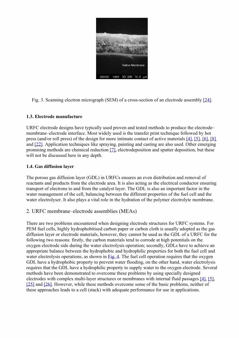