a review of in nyc
TRANSCRIPT

ON IT

A REVIEW OF STRAY VOLTAGE IN NYC
Data provided by ConEdPowerPoint by Roger Lane

My Goal in January 2004 & Now
Safer Streets in NYC
Materially reduce the risk to the pedestrian from SV

Motivation to Fix the Problem
The big pictureAll systems decay over timeIf the system does not have an effective and timely way to detect system failures, these defects will accumulateThe accumulated system failures will injure pedestrians
What does this mean to you?On average in Manhattan you pass a SV every half mile. When you walked from the subway in Union Square to Irving Place today you walked passed one SV. The number of undetected SV that you passed was likely higher. The number of system failures higher still.

The Chronology of SV
The electrical distribution system decays over timeThe decay reaches a point where a conductor is exposed. This is system failure.If a contact path is created to the surrounding structures, then SV is createdThe contact path may come and go, therefore SV may come and goThe decay → exposed conductor → “system failure”remains until detected and mitigated. This is the pedestrian risk.

What is Stray Voltage?
Stray Voltage is voltage detected in a location where it should not be present.If the electrical distribution system were working as designed there would be no stray voltage.
Cause: a failure of the electrical distribution system.Effect: Stray Voltage.Impact: Pedestrian risk of injury or death

3 Years have Past, What Has Been Done?
The distribution system of 739,000 locations had been tested 4 times: 1x in 2004, 1x in 2005 and 2x in 2006This means more than 3 million measurements have been taken for SVNYC may be the most tested distribution system in the U.S.A unique and more comprehensive mobile SV testing system was created and implemented.This mobile system searches for SV from all sources: ConEd, DOT, Customer, NYFD, NYPD, Contractors, CATV

3 Years have Past, What Has Been Found?
System failures are more widespread than expected
8,223 locations had Stray VoltageOn average, 9 SV locations detected every day in 2006
704 people were shockedOn average, one person shocked every other day in 2006

3 Years have Past, What Has Been learned?
SV comes and goes…the decay is permanentThis intermittency leads to SV detection that is not 100% effective at finding all system failures…false negatives are the result of this intermittencyWe know that the system decays but we don’t know at what rate or if the rate is changingMore frequent testing and more comprehensive test methods are leading to increased numbers of Detected SV

3 Years have Past, What Can We Surmise?
IF THERE IS NO COMPREHENSIVE, EFFECTIVE, AND FREQUENT METHOD OF SV DETECTION & MITIGATION THERE WILL CONTINUE TO BE LARGE NUMBERS OF UNDETECTED SYSTEM FAILURES AND LARGE NUMBERS OF UNDETECTED SV IN THE SYSTEM.In all years prior to 2004 this was true. Undetected system failures and undetected SV grew & accumulated since the beginning of the ConEdsystem.

3 Years have Past, What Can We Surmise?
During 2004 thru the present a more thorough test process was put in place. However, since these tests were ONLY SEMI ANNUAL and because SV comes and goes we can surmise that not all SV is detected as it occurs and not all system failures have been detected or will be detectedHuman and animal shock events will continuePedestrians will still be at risk

What Can You Do To Materially Improve Pedestrian Safety?
Redesign and rebuild the system to include:New designs that reduce the rate of decay of the system Continuous detection of SV and automatic mitigation when SV occursNew designs that add passive barriers e.g. non conductive materials
Develop a detection device and implement in the system or on the739,000 locations.
as a community of utility engineers create a consensus definition of requirements of such a deviceEncourage / incentivize Universities and Technology businesses to design and develop the device/system
Use mobile trucks or another comprehensive detection system to achieve at least every other week evaluation of the system

What Can We Do Today To Materially Improve Pedestrian Safety in NYC?
The only way to find all of the accumulated undetected system failures is to continually test for SV. Whenever the low impedance path is made the SV will be detected.In the near term, to achieve a 90% reduction of undetected SV, test the system every other week…Add 40 More mobile trucks

Your contribution to a solution is not unnoticed
Thank you for the work you are doing

2007 Jodie Lane National Conference for Stray Voltage Detection,2007 Jodie Lane National Conference for Stray Voltage Detection, Mitigation & PreventionMitigation & Prevention
2007 Jodie Lane National 2007 Jodie Lane National Conference for Stray Voltage Conference for Stray Voltage
Detection Mitigation and Detection Mitigation and PreventionPrevention
June 5June 5thth 20072007AgendaAgenda

2007 Jodie Lane National Conference for Stray Voltage Detection,2007 Jodie Lane National Conference for Stray Voltage Detection, Mitigation & PreventionMitigation & Prevention
Agenda Day OneAgenda Day One
Five Topics Relevant to the Subject MatterFive Topics Relevant to the Subject Matter–– Measurement and DetectionMeasurement and Detection–– MitigationMitigation–– Case StudiesCase Studies–– Analysis of DataAnalysis of Data–– Roundtable DiscussionRoundtable Discussion
Neutral Corrosion Neutral Corrosion –– Cable ReplacementCable ReplacementTransmission Testing for Stray VoltageTransmission Testing for Stray VoltageDevelopment of New ToolsDevelopment of New Tools

Stray Voltage UpdateJune 5, 2007

18
Con Edison Service Territory
Con Edison Company of NYCon Edison Company of NYNYC and WestchesterNYC and WestchesterArea: 660 sq. mi. (Elec & Gas)Area: 660 sq. mi. (Elec & Gas)Population: Population: 9.1million9.1million
3.1 million electric 3.1 million electric customerscustomers13,141 MW 2006 13,141 MW 2006
PeakPeakIn some areas, Load In some areas, Load
Density greater than Density greater than 2100 MW per Sq Mile2100 MW per Sq Mile

19
Mission
“Protect the public and improve public safety through the mitigation and elimination of stray voltage”

20
Stray Voltage Mitigation Strategy
• Testing– Detect, protect, and repair stray voltage before the public
• Inspection– Find and repair possible precursors to stray voltage
• Design / Rebuild– Implement improved designs to mitigate stray voltage– Continually renovate the system
• Research and Development Initiatives– Never status quo, innovation
• Awareness– Industry and public

21
Electric Shock Reduction (Jan 1- Apr 30)
Total Electric Shocks Reported
55
72
107
148
0
20
40
60
80
100
120
140
160
2004 2005 2006 2007Year
Num
ber o
f Ele
ctric
Sho
cks 28%
33%
24%

22
Electric Shock Reduction (Jan 1- Apr 30)
Electric Shocks Reported (conEd)
20
42
71
128
0
20
40
60
80
100
120
140
2004 2005 2006 2007Year
Num
ber o
f Ele
ctric
Sho
cks 45%
41%
52%

Manual Testing

24
Stray Voltage Testing
To test all company facilities and streetlights for stray voltage
-274,000 underground structures-285,000 overhead poles-177,000 streetlights

Mobile Stray Voltage Program

26
Mobile Detector Program
• Detector certified to detect 6V at 25ft, 20mph• 4 system wide scans planned for 2007
• Major improvements over manual testing– Sensitivity– Speed– Flexibility– Test entire environment– Proactive

27
Additional Public Safety Benefit
• Extend testing to whole environment has significant impact on safety
• Only 275 (6% of all detected) on Company owned assets
Non Con Edison Stray Voltage Sources Found by
CE Forces Using SVDSVD Stray Voltage Not Tested
in Manual ProgramsSidewalk 330Gate 111Scaffolding 76Cust Eqp 61Bus Shelter 39Phone Booth 23Non-CE Cover 20Fire Hydrant 18Other 3Water Pipe 2Trench 1Total 684
(Totals for 06/07 Rate Year, plus April 2007)

Structure Inspection Program

29
Structure Inspection Program
• Scope of ProgramTo conduct inspections of all underground and overhead facilities, perform repairs and identify rebuild areas
• Inspection Progress- 533,000 inspections completed

Rebuild Program

31
Rebuild Program
• Scope of ProgramIdentify area of repairs, issue layouts and prioritize Construction work
– 70,000 miles secondary cable on system– Replace 2,000 miles of cable per year– 30-40 year replacement cycle – 8,000 miles installed

Engineering / Design Programs

33
Streetlight Isolation Transformers

34
Streetlight Painting Program
• New York City DOT program• Insulating paint rated to protect up to 20V• DOT has completed 80% of 177K streetlights & traffic lights
to date

35
Streetlight Safetap
• Streetlight Safetap®– Provides a quick, convenient
source of 120 volt temporary power from streetlights using existing fuse holders
Safety Steps

Research and Development

37
Monitoring of Service Boxes & Manholes
• Power Line Carrier• 13 sensors and 1 collector
installed 2006• Local communication verified• Establishing communication to
the end user

38
Network Transformer Vault Monitoring
• Sensor developed and installed at a network transformer vault for testing

39
Real Time Monitoring: Streetlight Photo Cell
Project started January 2007• 25 Photo Cells, 1 Node installed • Wireless lamp status reporting at 4 hr interval• Investigating potential incorporation of stray voltage sensing
capability
PHOTO CELL NODE

Composite Covers

41
• Non Conductive• Pilot Program to install 1000
covers Fall 2007• Blast tests• ADA Compliant• Field Demonstrations
– Weight – 125 lbs– Non corrosive– Slip resistant
Vented Composite SB Cover

Stray Voltage Performance

43
Stray Voltage Conditions Found vs Number of Tests Performed
2,384 2,508
3,331 3,189
1,534,000
831,000
1,090,000924,000
1,0001,5002,0002,5003,0003,5004,0004,5005,000
2004 2005 2006 2007(4/30/07)
Year
Num
ber o
f Str
ay V
olta
ge
Con
ditio
ns
0200,000400,000600,000800,0001,000,0001,200,0001,400,0001,600,0001,800,000
Test
s Pe
rfor
med

44
Stray Voltage Locations
ESR Locations2004 to 4/30/07
13%
44%
1%
25%17%
ENE Locations2004 to 4/30/07
85%
1%
3%6%
5%conEd Structures
Sidewalks
Non-conEdStructures*
OverheadInfrastructure
Streetlights
*Non-conEd structures include Cust. Equipt., Awnings, Fences, Hydrants and Scaffold

45
Root Cause Ownership for SV Detected/Reported
SV Detected in 2007 Only
All Others65%
Con Ed35%
SV Detected 2004 to 2007 YTD
All Others55%
Con Ed45%

Awareness

47
Awareness 2007
• Jodie Lane Conference (NYC)• Electrical Network Systems Conference (Columbia, SC)• EUCI - Neutral Grounding SV Seminar (San Diego, CA)• IEEE – Conference (Orlando, FL)
– Working group webcasts (two this year)• Utility Safety Conference (Seattle, WA)• Western Energy InstituteConference (Phoenix, AZ)

48
Awareness
• City agency training and awareness– DOT, NYPD, FDNY/EMT
• Presentations to public officials & Community Boards• NYC Department of Buildings

49
Customer Awareness
• Customer reported shock from stove in Westchester• Customer reported shock from faucet in Brooklyn• Customer reported shock on front porch in Brooklyn• Customer reported shock while washing deck in Staten
Island• Person reported shock on fifth floor of office building in
Manhattan• Person shocked from circuit panel in basement in
Brooklyn

Questions?

8/6/2007 51
2007 Jodie Lane Conference for Urban Stray Voltage Detection Mitigation and Prevention
Underground Electrical Safety Program
NSTAR Distribution Technical Engineering
Christopher P. O’Neil P.E.
June 5 & 6, 2007

5/24 DRAFT2007 Jodie Lane National Conference for Stray Voltage Detection,2007 Jodie Lane National Conference for Stray Voltage Detection, Mitigation & PreventionMitigation & Prevention
NSTAR Electric
81 communities1.1 million electric customers5,000 MW demand
ELECTRIC DELIVERY SERVICE AREA
Boston

5/24 DRAFT2007 Jodie Lane National Conference for Stray Voltage Detection,2007 Jodie Lane National Conference for Stray Voltage Detection, Mitigation & PreventionMitigation & Prevention
Overview - Overhead Distribution System
• 4kV: 331 circuits, 1,943 circuit miles, serving 208,000 customers (approx. 20% of total NSTAR customers)
15kV: 324 circuits, serving 418,000 customers (approximately 40% of total NSTAR customer base)
• 25kV: 210 circuits, serving 220,000 customers (approx. 21% of total NSTAR customers)

5/24 DRAFT2007 Jodie Lane National Conference for Stray Voltage Detection,2007 Jodie Lane National Conference for Stray Voltage Detection, Mitigation & PreventionMitigation & Prevention
Overview - Underground Distribution System
Approximately 39,000 Manholes
• 4kV: 276 circuits, 900 circuit miles, serving 110,000 customers
• 15kV (excluding DSS): 128 circuits, serving 47,000 customers (approximately 4.4% of total NSTAR customer base)
• 15kV Distribution System Supply (DSS) Lines: 375 lines
• Network: 150 network feeders and 1,500 transformers
• URD: Over 2,660 miles of 15 & 25kV cable– Over 800 miles of direct buried HMWPE non-jacketed cable

5/24 DRAFT2007 Jodie Lane National Conference for Stray Voltage Detection,2007 Jodie Lane National Conference for Stray Voltage Detection, Mitigation & PreventionMitigation & Prevention
UNDERGROUND ELECTRICAL SAFETY PROGRAM
The Underground Electrical Safety Program is an incremental effort undertaken by NSTAR over and above its existing work plans to improve service and reliability levels for our customers.
The Program is designed to meet three objectives:(1) to assess the condition of infrastructure in use on the NSTAR
Electric system;
(2) to identify infrastructure that needs repair, replacement orremediation; and
(3) to complete high priority repairs, replacements and remediation of that equipment on a timely basis.

5/24 DRAFT2007 Jodie Lane National Conference for Stray Voltage Detection,2007 Jodie Lane National Conference for Stray Voltage Detection, Mitigation & PreventionMitigation & Prevention
The 2006 work plan:• Manhole inspections (approximately 5,500) and completion of
inspection-related repairs, replacements and remediation.
• Stray voltage-indication testing (approximately 40,000) and any subsequent repairs and remediation of NSTAR-owned secondary risers, secondary pedestals and padmount transformers in any location served by the underground distribution system and accessible to the public;
• Visiting sites identified in 2,831 demolition permits within the City of Boston to validate that service cutoffs are complete;
• Evaluation, assessment and potential deployment of new technology and equipment;
• Development of information systems to track inspections and compile results; and
• Forensic analysis of failed equipment.

5/24 DRAFT2007 Jodie Lane National Conference for Stray Voltage Detection,2007 Jodie Lane National Conference for Stray Voltage Detection, Mitigation & PreventionMitigation & Prevention
Prioritization:
• Facilities within the City of Boston and City of Cambridge for investigation through the Underground Electrical Safety Program.These systems were tested in their entirety in year one because these systems represent the majority of NSTAR Electric’s underground infrastructure.
• During the second quarter, NSTAR finalized and implemented a new manhole inspection form. This scannable form will aid in tracking all inspections and subsequent repairs entered into thecompany’s manhole database.
• NSTAR developed deficiency criteria to define high-priority follow-up work. This two-tier criteria approach is based on an analysis of inspections performed in the first quarter, which identified manholes with equipment and design considerations, along with cable and joint support deficiencies.

5/24 DRAFT2007 Jodie Lane National Conference for Stray Voltage Detection,2007 Jodie Lane National Conference for Stray Voltage Detection, Mitigation & PreventionMitigation & Prevention
Underground Electrical Safety Program-Manholes

5/24 DRAFT2007 Jodie Lane National Conference for Stray Voltage Detection,2007 Jodie Lane National Conference for Stray Voltage Detection, Mitigation & PreventionMitigation & Prevention
Highlights 2006 Manhole Program:
• NSTAR performed 1,224 network manhole inspections over the year. These were targeted inspections to verify records, condition of secondary mains, and secondary limiters placement and condition.
• As a result of planned work during the year an additional 4,468 manholes were inspected.
• Overall, NSTAR completed 5,692 manhole inspections. During this same period, remediation activities focused on high-priority repairs identified. 706 of these maintenance upgrades were completed at year end.
• In addition to these inspections, the Company checked on the cut-off status of 2,517 demolition locations during the course of the year.

5/24 DRAFT2007 Jodie Lane National Conference for Stray Voltage Detection,2007 Jodie Lane National Conference for Stray Voltage Detection, Mitigation & PreventionMitigation & Prevention
Verification of Demolition Cut-Offs
• As part of the inspection process, the Company identified the location of suspected service cutoffs relating to building demolitions. Of the 2517 locations checked, the Company was able to verify the cutoff status of all locations.
• Of the 2,517 locations, 1,450 service cables were verified cut in the manhole and 1,029 services were verified connected to an active service account. These locations did not require further action.
• 38 service cables was discovered not connected to a facility and subsequently de-energized.

5/24 DRAFT2007 Jodie Lane National Conference for Stray Voltage Detection,2007 Jodie Lane National Conference for Stray Voltage Detection, Mitigation & PreventionMitigation & Prevention
Underground Electrical Safety Program – Stray Voltage

5/24 DRAFT2007 Jodie Lane National Conference for Stray Voltage Detection,2007 Jodie Lane National Conference for Stray Voltage Detection, Mitigation & PreventionMitigation & Prevention
Highlights 2006 Stray Voltage testing:
• NSTAR performed 53,198 stray voltage tests.
• The Sarnoff test vehicle was used on a five-day, off-shift schedule, with a focus on the downtown Boston and surrounding areas. Testing was completed on all required facilities.
• The Sarnoff vehicle was responsible for 89% of all positive stray-voltage detections in 2006. NSTAR Electric verified that 2,517 demolished locations have been cut off, or have an existing active service.

5/24 DRAFT2007 Jodie Lane National Conference for Stray Voltage Detection,2007 Jodie Lane National Conference for Stray Voltage Detection, Mitigation & PreventionMitigation & Prevention
Stray-Voltage Testing
• A complete sweep of the city of Boston and the city of Cambridge have been tested for stray voltage.
• The Company detected, and subsequent repairs have been made at 71 locations which tested positive for the presence of stray voltage. 10 of the 71 positive locations were NSTAR owned equipment.
• NSTAR Electric follows a “Find It, Fix It” principle with coordination of the owner of issue in circumstances where the affected equipment was not NSTAR Electric-owned

5/24 DRAFT2007 Jodie Lane National Conference for Stray Voltage Detection,2007 Jodie Lane National Conference for Stray Voltage Detection, Mitigation & PreventionMitigation & Prevention
Questions?
ScheduledBreak

2007 Jodie Lane Conference for Urban Stray Voltage Detection Mitigation and Prevention
Nuisance Shocking
NSTAR Distribution Technical Engineering
Christopher P. O’Neil P.E.
June 5 & 6, 2007

5/24 DRAFT2007 Jodie Lane National Conference for Stray Voltage Detection,2007 Jodie Lane National Conference for Stray Voltage Detection, Mitigation & PreventionMitigation & Prevention
Elevated Neutral to Earth Voltage vs.
Inadvertent Contact voltage • The subject of “Stray Voltage” has long been an area of
concern and subjective interpretation for utilities, regulators and the public. Issues range from induction of voltage onto metallic infrastructure such as conduits, shield wires, water lines, and gas lines to unanticipated current paths created by grounding configurations and connection impedances.
• Recent events have confused the usage of this term so that the general public now associates it with dangerous voltages which might result in injury. The historical usage of the term “stray voltage” is associated with a non hazardous elevated neutral voltage

5/24 DRAFT2007 Jodie Lane National Conference for Stray Voltage Detection,2007 Jodie Lane National Conference for Stray Voltage Detection, Mitigation & PreventionMitigation & Prevention
What is Elevated Neutral to Earth Voltage?
• Normal Load, and fault currents flowing through the impedances of the neutral or grounding conductors to earth, produce neutral to earth voltage (NEV) . There are multiple paths from the neutral or grounding system to earth such as ground rods, metallic water lines, or other ground electrodes. This means that there is always voltage to earth. Any metallic structure connected to the neutral or the grounding system will also be at the same NEV.

5/24 DRAFT2007 Jodie Lane National Conference for Stray Voltage Detection,2007 Jodie Lane National Conference for Stray Voltage Detection, Mitigation & PreventionMitigation & Prevention
What is Inadvertant Contact Voltage?
• Contact voltage occurs when an energized electric line inadvertently comes in full or partial contact with earth or a metalic object. The contact can be due to a breakdown of the electric insulation, from an improper connection, damage from a vehicle accident, vandalism, or a cable being dug up accidentally.

5/24 DRAFT2007 Jodie Lane National Conference for Stray Voltage Detection,2007 Jodie Lane National Conference for Stray Voltage Detection, Mitigation & PreventionMitigation & Prevention
NSTAR Electric
81 communities1.1 million electric customers5,000 MW demand
ELECTRIC DELIVERY SERVICE AREA
Boston

5/24 DRAFT2007 Jodie Lane National Conference for Stray Voltage Detection,2007 Jodie Lane National Conference for Stray Voltage Detection, Mitigation & PreventionMitigation & Prevention
Stray Voltage on the Cape -Summary• Complaints are received annually from customers receiving
shocks on outside showers/water faucets in the Cape District. These calls are not localized.
• As with typical rural distribution systems the problem arises particularly due to the following:– Distribution system, with predominant single phase loading, difficult
to balance.– Redundant paths to hardwired multipoint grounded system neutral do
not exist throughout the Cape as they do in urban areas. • Municipal water systems, Gas, Communication
– Distribution Supply circuits that share a transmission corridor– High soil resistivity,– Intermittent equipment locations resulting ,sparse grounding, of
system neutral, – Increased commercial & residential harmonic loading – People barefoot in wet conditions and the above are the ideal
parameters to generate ENV (elevated neutral voltage) and Metallic Object to Earth Voltage (MOEV) at or near the level of perception

5/24 DRAFT2007 Jodie Lane National Conference for Stray Voltage Detection,2007 Jodie Lane National Conference for Stray Voltage Detection, Mitigation & PreventionMitigation & Prevention
What level of stray voltage is a concern?
• The Massachusetts Department of Telecomunication and Energy {now DPU} has ordered immediate repair if there is a voltage reading of 20 volts or greater. If the voltage reading is between 8 and 20 volts, repairs must be made within 24 hours. Mitigation of voltage readings below 8 volts is left to the discretion of the Utility.
• It is recommended that actions be taken to reduce neutral to earth voltage when the NEV at the service entrance or between contact points is higher than the 2 to 4 volts range level. Unfortunately, there is no standard for stray voltage and this is only a recommend guideline from the U.S. Department of Agriculture.
• A standardized measurement of stray voltage is defined as "the voltage measured across a 500 ohm (nominal) resistance connected between two animal contact points."

5/24 DRAFT2007 Jodie Lane National Conference for Stray Voltage Detection,2007 Jodie Lane National Conference for Stray Voltage Detection, Mitigation & PreventionMitigation & Prevention
Where does Elevated NEV come from?
• Utility Sources of stray voltage include, but are not limited to; electrical shorts {Transient faults } in equipment, defective underground cable, unbalanced loads that result in a voltage drop on neutral conductor, corroded neutrals, corroded bonding connections, and missing or inadequate grounding systems.
• A common private property source of stray voltage is the result of interconnection of equipment grounding conductors with the neutral conductors. The grounding conductor is used to ground metal equipment and should never be one of the conductors used to supply power. The neutral, or other conductor supplying power, should never be connected to the metal case of equipment nor should it be interconnected with the grounding conductor at any point other than the main electric service panel.

5/24 DRAFT2007 Jodie Lane National Conference for Stray Voltage Detection,2007 Jodie Lane National Conference for Stray Voltage Detection, Mitigation & PreventionMitigation & Prevention
Multi-Grounded Neutral (MGN) –Multiple return paths

5/24 DRAFT2007 Jodie Lane National Conference for Stray Voltage Detection,2007 Jodie Lane National Conference for Stray Voltage Detection, Mitigation & PreventionMitigation & Prevention
Separating the neutral from the equipment grounds
Normal current on Equip Gnd = 0

5/24 DRAFT2007 Jodie Lane National Conference for Stray Voltage Detection,2007 Jodie Lane National Conference for Stray Voltage Detection, Mitigation & PreventionMitigation & Prevention
Separating the neutral from the equipment grounds
Normal neutral current takes shared path

5/24 DRAFT2007 Jodie Lane National Conference for Stray Voltage Detection,2007 Jodie Lane National Conference for Stray Voltage Detection, Mitigation & PreventionMitigation & Prevention
First Call Response - Cover the Basics
• Determine the source. Transient fault or normal neutral current. On property or off property
• Inspect the continuity and resistance of the circuit neutral path back to the source transformer. Replace defective or questionable connections and fill in any sections of discontinuities.
• Survey/reinforce distribution system neutral on circuits. Ensure continuity toward source and drive multiple deep earth grounds min 8x per mile equipment.
• Ensure multiple redundant neutral return paths through intersystem bonding with communication messengers as now required NESC rule 97G.

5/24 DRAFT2007 Jodie Lane National Conference for Stray Voltage Detection,2007 Jodie Lane National Conference for Stray Voltage Detection, Mitigation & PreventionMitigation & Prevention
NEW NESC Requirement 2007
interconnect telecom/Cat
messenger with ground
Similar common bonding on both sides of the service point.

5/24 DRAFT2007 Jodie Lane National Conference for Stray Voltage Detection,2007 Jodie Lane National Conference for Stray Voltage Detection, Mitigation & PreventionMitigation & Prevention
ANSI Standard 3Phase 4WireMultipoint Grounded Neutral
• Multi point grounded electric systems use the ground (or earth) as a common medium to supplement the return of current to the local electric substation or generating plant. Neutral-earth currents typically exist wherever electric power distribution exists. TheNational Electric Code and National Electric Safety Code define proper techniques for grounding on a utility’s electric system and at residential and commercial structures and buildings. Electric utilities, such as NSTAR, adhere strictly to all NESC codes, in the design and construction of their electric systems.
• Minimizes Hazardous Voltages to Ground
• Provides Low Impedance Path for Ground Faults
• Provides better Grounding for Lightning Protection
• This added safeguard over three phase three wire is more costly by the installation of the 4th neutral wire and multiple down ground connections

5/24 DRAFT2007 Jodie Lane National Conference for Stray Voltage Detection,2007 Jodie Lane National Conference for Stray Voltage Detection, Mitigation & PreventionMitigation & Prevention
Current on the Neutral path• Currents returning on grounded-wye power systems cause a
voltage drop across the impedance of the neutral conductor. Because the neutral conductor is grounded, the impedance of the earth return path in parallel with the impedance of the neutral return path dictates the percentage of earth current and the corresponding NEV at that neutral-grounding point. Current will follow on all return paths in proportion to the conducting path impedances.
• Reducing the impedance of the neutral effectively reduces the amount of current flowing through the earth path and lowers corresponding NEV at that neutral-to-ground bonding point.– Increase neutral capacity = reduce voltage drop = reduce
potential difference between earthing connection.
• Multipoint low impedance driven grounds ensure effective overcurrent protection during transient single line to ground SLTG faults
• Multiple redundant hardwired return paths are required to supplement earth return and increase neutral capacity.

5/24 DRAFT2007 Jodie Lane National Conference for Stray Voltage Detection,2007 Jodie Lane National Conference for Stray Voltage Detection, Mitigation & PreventionMitigation & Prevention
Load balancing
• On three-phase, grounded-wye distribution systems with equally balanced 60-Hz phase currents, the net neutral current should be zero. That is, the neutral current from the three phases effectively cancels out. Unfortunately, in the real world, perfect balancing can be upset by many factors such as phase shift, load unbalance and harmonic currents. These phenomena can cause current to flow in the neutral conductor and into the ground rod at each of the neutral-to-ground bonding points, which creates a proportional NEV. Balancing the phase currents can reduce the 60-Hz component of NEV across the entire distribution system.

5/24 DRAFT2007 Jodie Lane National Conference for Stray Voltage Detection,2007 Jodie Lane National Conference for Stray Voltage Detection, Mitigation & PreventionMitigation & Prevention
Harmonic filtersLimit @ service point to IEEE 519
• A recent area of research into NEV concern relates to 3rd harmonic currents flowing on distribution system neutral conductors. This and other odd multiples of the fundamental 60-Hz current add instead of canceling out on the neutral conductor, thereby creating harmonic NEV levels. The causes of these harmonic currents include harmonic generating equipment owned by the end user and circuit resonances created by distributed capacitor banks. Harmonics dueto customer loads is expected to increase over time as more equipment such as variable frequency drive washers and air conditioning equipment proliferate and as more televisions, PCs and other home entertainment equipment use increases.
• IEEE 519 WORKING GROUP IEEE Standard Practices and Requirements for Harmonic Control inElectrical Power Systems

5/24 DRAFT2007 Jodie Lane National Conference for Stray Voltage Detection,2007 Jodie Lane National Conference for Stray Voltage Detection, Mitigation & PreventionMitigation & Prevention
Adequate Service and Equipment Grounding
• Provide adequate electric service and equipment grounding. Customer to ensure effective equipment grounding path to all metal equipment likely to become energized. Separate from neutral beyond the service point main. Provide low resistance equipment ground fault clearing path.
• An effective ground-fault current path must be capable of safely carrying the maximum fault current likely to be imposed on it from any point on the wiring system where a ground fault may occur to the electrical supply source neutral. Effective ground path = trips overcurrent
• Uniform ground potential rise and better grounding provides effective ground path. Proper installation of an equipotential plane, a grounding grid in the floor that's connected to all metallic equipment.

5/24 DRAFT2007 Jodie Lane National Conference for Stray Voltage Detection,2007 Jodie Lane National Conference for Stray Voltage Detection, Mitigation & PreventionMitigation & Prevention
Equipotential Plane; NEC Agricultural Buildings, Swimming Pools, Fountains &
Similar
• Similar to the ground-reference structures used for computer rooms and the ground mats that minimize step potentials at utility substations, the equipotential plane is a useful means of minimizing the effects of stray voltage.
• An equipotential plane typically consists of a conductive wire mesh installed under the area where nuisance shocking has been reported, and bonding conductive materials in the area directly to the mesh. The technique does not reduce NEV levels, but rather provides a uniform voltage gradient in areas where people and animals are likely to insert themselves into the conducting path.
• Bring the outdoor shower into compliance with current NEC requirements and help mitigate the problem as well (NEC requirement Article 547 agriculture locations and 680 Pools & Aquatic environments such as outdoor showers).

5/24 DRAFT2007 Jodie Lane National Conference for Stray Voltage Detection,2007 Jodie Lane National Conference for Stray Voltage Detection, Mitigation & PreventionMitigation & Prevention
Summary ENV Specific Chalanges• It is desirable to keep NEV below the level of perception
where practical. Two to four volts of NEV should be reduced where practical. Urgency to reduce the voltage increases rapidly with higher voltages.
• Intrinsically safe voltage levels at that of perception less than 1V are and will continue to be a public concern
• Rural areas, limited redundant paths, phase balancing and hardwired neutral capacity generalized contributor of high NEV.

5/24 DRAFT2007 Jodie Lane National Conference for Stray Voltage Detection,2007 Jodie Lane National Conference for Stray Voltage Detection, Mitigation & PreventionMitigation & Prevention
Wrap - Up
• NSTAR Electric is Committed to Delivering Great Service, and Safe & Reliable Energy
• We must strive to provide accurate information on our efforts to minimize the effect elevated neutral voltages and high soil resistivity in areas.
• Employees, Customers and the Press need to be reassured that the safety of our customers and our system is foremost.

2007 Jodie Lane National Conference for Stray Voltage Detection,2007 Jodie Lane National Conference for Stray Voltage Detection, Mitigation & PreventionMitigation & Prevention
Stray Voltage at aStray Voltage at aRemotely Operated Gas ValveRemotely Operated Gas Valve
Benjamin Brown Benjamin Brown –– Orange & Rockland Orange & Rockland [email protected]@oru.com
June 5, 2007June 5, 2007

2007 Jodie Lane National Conference for Stray Voltage Detection,2007 Jodie Lane National Conference for Stray Voltage Detection, Mitigation & PreventionMitigation & Prevention
OverviewOverviewOrange and RocklandOrange and Rockland’’s Territory & Electric s Territory & Electric
SystemSystem
Case BackgroundCase Background
Investigation and Mitigation EffortsInvestigation and Mitigation Efforts
Solution & ResultsSolution & Results
Lessons LearnedLessons Learned

2007 Jodie Lane National Conference for Stray Voltage Detection,2007 Jodie Lane National Conference for Stray Voltage Detection, Mitigation & PreventionMitigation & Prevention
Orange and RocklandOrange and Rockland’’s Territory s Territory and Electric Systemand Electric System
Territory:Territory:Rockland, Orange and Sullivan Counties, New YorkRockland, Orange and Sullivan Counties, New YorkParts of Northern New JerseyParts of Northern New JerseyPike County, PennsylvaniaPike County, PennsylvaniaApproximately 1,300 square miles, serving 294,000 customersApproximately 1,300 square miles, serving 294,000 customers
Transmission system:Transmission system:Operating voltages of 345kV, 138kV, 69kV and 34kVOperating voltages of 345kV, 138kV, 69kV and 34kVNearly 300 miles and 3,500 acres of rightNearly 300 miles and 3,500 acres of right--ofof--wayway
Distribution system:Distribution system:OpenOpen--looped overhead radial system interspersed with underground looped overhead radial system interspersed with underground residential distribution (URD)residential distribution (URD)Operating voltages of 34.5kV, 13.2kV and 4kVOperating voltages of 34.5kV, 13.2kV and 4kVApproximately 4,300 circuit miles of overhead and underground caApproximately 4,300 circuit miles of overhead and underground cableble

2007 Jodie Lane National Conference for Stray Voltage Detection,2007 Jodie Lane National Conference for Stray Voltage Detection, Mitigation & PreventionMitigation & Prevention
BackgroundBackgroundGas Crews raised a safety concern:Gas Crews raised a safety concern:
Getting shocked while working at the Remotely Operated Valve Getting shocked while working at the Remotely Operated Valve (ROV)(ROV)Noticed arcing between the two inch stanchion and one inch tap Noticed arcing between the two inch stanchion and one inch tap pipes on either sidepipes on either sideRecorded between 9.4VAC and 21.4VAC at the ROV depending on Recorded between 9.4VAC and 21.4VAC at the ROV depending on the reference point usedthe reference point used
Remotely Operated Valve location:Remotely Operated Valve location:
Approximately 300 feet from a 138/13.2 kV distribution substatioApproximately 300 feet from a 138/13.2 kV distribution substationnDirectly beneath two 138kV transmission linesDirectly beneath two 138kV transmission lines

Remotely Operated Valve (ROV)Remotely Operated Valve (ROV)

Gas 16” Transmission Mains
138kV Electric Transmission
Area MapArea Map
Rectifier
Remotely Operated Valve

2007 Jodie Lane National Conference for Stray Voltage Detection,2007 Jodie Lane National Conference for Stray Voltage Detection, Mitigation & PreventionMitigation & Prevention
InvestigationInvestigationGas rectifier:Gas rectifier:
Checked equipment and found there was an AC Checked equipment and found there was an AC component to the DC outputcomponent to the DC output
Electric transmission and distribution system:Electric transmission and distribution system:Installed additional grounds at all distribution poles in the Installed additional grounds at all distribution poles in the areaareaInstalled strain rod and reinsulated the pole servicing Installed strain rod and reinsulated the pole servicing rectifierrectifierConcluded that terrain environment contributed to Concluded that terrain environment contributed to natural or baseline voltage of 3.5VACnatural or baseline voltage of 3.5VACDetermined that the system neutral voltage was Determined that the system neutral voltage was impressed on the secondary neutralimpressed on the secondary neutral

2007 Jodie Lane National Conference for Stray Voltage Detection,2007 Jodie Lane National Conference for Stray Voltage Detection, Mitigation & PreventionMitigation & Prevention
SolutionSolutionElectric distribution system modifications:Electric distribution system modifications:
Installed a neutral isolator at the transformer pole servicing tInstalled a neutral isolator at the transformer pole servicing the he rectifierrectifierSeparated the system and secondary neutrals at the pole adjacentSeparated the system and secondary neutrals at the pole adjacentto rectifierto rectifier
Gas rectifier:Gas rectifier:Installed capacitor filter on rectifierInstalled capacitor filter on rectifier
Gas operating procedural changes:Gas operating procedural changes:Temporarily bond the various stanchions at the ROV prior to Temporarily bond the various stanchions at the ROV prior to performing workperforming workDisable rectifier while working at the ROVDisable rectifier while working at the ROV
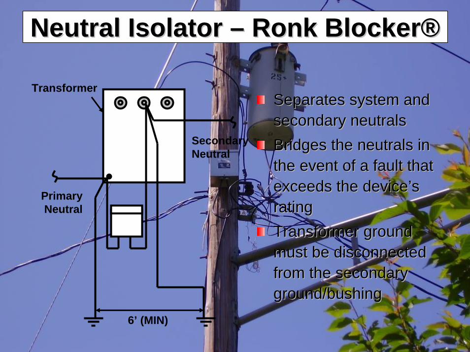
Separates system and Separates system and secondary neutralssecondary neutralsBridges the neutrals in Bridges the neutrals in the event of a fault that the event of a fault that exceeds the deviceexceeds the device’’s s ratingratingTransformer ground Transformer ground must be disconnected must be disconnected from the secondary from the secondary ground/bushingground/bushing
Secondary Neutral
Primary Neutral
Transformer
6’ (MIN)
Neutral Isolator Neutral Isolator –– Ronk BlockerRonk Blocker®®

2007 Jodie Lane National Conference for Stray Voltage Detection,2007 Jodie Lane National Conference for Stray Voltage Detection, Mitigation & PreventionMitigation & Prevention
ResultsResults
Mitigated voltage readings to baselineMitigated voltage readings to baselineReacquired confidence of gas personnel Reacquired confidence of gas personnel to safely work on ROVto safely work on ROVImproved pedestrian safety from possible Improved pedestrian safety from possible stray voltage along electric distribution stray voltage along electric distribution system system

2007 Jodie Lane National Conference for Stray Voltage Detection,2007 Jodie Lane National Conference for Stray Voltage Detection, Mitigation & PreventionMitigation & Prevention
Lessons LearnedLessons Learned
Standard and proven investigation Standard and proven investigation techniques successfully usedtechniques successfully usedClose cooperation between electric and Close cooperation between electric and gas necessary when cogas necessary when co--locating critical locating critical facilities on common propertyfacilities on common property

2007 Jodie Lane National Conference for Stray Voltage Detection,2007 Jodie Lane National Conference for Stray Voltage Detection, Mitigation & PreventionMitigation & Prevention
Thank youThank you
Benjamin Brown Benjamin Brown –– Orange & Rockland Orange & Rockland [email protected]@oru.com

Case Study
Graciela VarelaDistribution EngineeringCon Edison

99
Additional Public Safety Benefit
• Extend testing to whole environment has significant impact on safety
Non Con Edison Stray Voltage Sources Found by
CE Forces Using SVDSVD Stray Voltage Not Tested
in Manual Programs
Sidewalk 330Gate 111Scaffolding 76Cust Eqp 61Bus Shelter 39Phone Booth 23Non-CE Cover 20Fire Hydrant 18Other 3Water Pipe 2Trench 1Total 684
(Totals for 06/07 Rate Year, plus April 2007)

100
Case Study: St. Catherine’s Church
Feb 28, 2007
112V on fence
Service duct cracked by tree roots under sidewalk
Detected by mobile detector and repaired

101

Questions?

2007 Jodie Lane National Conference for Stray Voltage Detection,2007 Jodie Lane National Conference for Stray Voltage Detection, Mitigation & PreventionMitigation & Prevention
Detection and Mitigation of Detection and Mitigation of Stray Voltage in Stray Voltage in
Underground Distribution Underground Distribution SystemsSystems
Aaron PrazanAaron PrazanConEdisonConEdison
[email protected]@coned.com
June 5th 2007June 5th 2007
David KalokitisDavid KalokitisPower Survey CompanyPower Survey Company
[email protected]@powersurveyco.com

2007 Jodie Lane National Conference for Stray Voltage Detection,2007 Jodie Lane National Conference for Stray Voltage Detection, Mitigation & PreventionMitigation & Prevention
IntroductionIntroduction
•• Aaron Prazan, EngineerAaron Prazan, EngineerConEdisonConEdison Distribution Engineering Distribution Engineering –– focused focused on analysis of testing and inspection programs on analysis of testing and inspection programs as part of a stray voltage mitigation strategyas part of a stray voltage mitigation strategy
•• David Kalokitis, CTODavid Kalokitis, CTOPower Survey Company Power Survey Company –– a technology and a technology and
service provider focused on detection and service provider focused on detection and mitigation of Stray Voltagemitigation of Stray Voltage

2007 Jodie Lane National Conference for Stray Voltage Detection,2007 Jodie Lane National Conference for Stray Voltage Detection, Mitigation & PreventionMitigation & Prevention
PresentationPresentation OverviewOverview
•• Stray Voltage ConcernsStray Voltage Concerns•• ChallengesChallenges•• Mitigation StrategyMitigation Strategy•• SV Emergence ModelingSV Emergence Modeling•• Mitigation Program FindingsMitigation Program Findings•• Mobile SV Detection Equipment & MethodsMobile SV Detection Equipment & Methods•• Troubleshooting ApproachTroubleshooting Approach•• ConclusionsConclusions

2007 Jodie Lane National Conference for Stray Voltage Detection,2007 Jodie Lane National Conference for Stray Voltage Detection, Mitigation & PreventionMitigation & Prevention
Mission StatementMission Statement
““Protect the public and improve public Protect the public and improve public safety through the mitigation and safety through the mitigation and
elimination of stray voltageelimination of stray voltage””

2007 Jodie Lane National Conference for Stray Voltage Detection,2007 Jodie Lane National Conference for Stray Voltage Detection, Mitigation & PreventionMitigation & Prevention
Stray Voltage ConcernsStray Voltage Concerns••Safety ConcernsSafety Concerns
––Hazard to general public (human and animal)Hazard to general public (human and animal)••Regulatory ComplianceRegulatory Compliance
––Increasing trend to mandate testingIncreasing trend to mandate testing••Operational EfficiencyOperational Efficiency
––Manual testing is time consuming, labor Manual testing is time consuming, labor intensive, limited to specific test objectintensive, limited to specific test object
––Testing activity should be performed in a Testing activity should be performed in a continuous mannercontinuous manner
––Test methods should uncover traditional and Test methods should uncover traditional and nonnon--traditional hazardstraditional hazards

2007 Jodie Lane National Conference for Stray Voltage Detection,2007 Jodie Lane National Conference for Stray Voltage Detection, Mitigation & PreventionMitigation & Prevention
StrategyStrategy:: Test, Inspect, Upgrade Test, Inspect, Upgrade
•• Reduce exposure nowReduce exposure now–– Multiple system testsMultiple system tests–– Corporate culture change/awareness Corporate culture change/awareness
•• Reduce emergence in futureReduce emergence in future–– Inspect & RepairInspect & Repair–– Capital improvementCapital improvement–– R&DR&D

Reduced Stray Voltage Exposure Thru Reduced Stray Voltage Exposure Thru Multiple ScansMultiple Scans
1 2 3 4 5 6 7 8 9 10 11 120100200300400500600700800
Search Frequency (surveys/year)
Predicted SV Exposure vs. # of Surveys
# of
SV
–– AssumptionsAssumptions•• New SV created over timeNew SV created over time•• Repeated testing to reduce Repeated testing to reduce
exposureexposure
–– Expected resultExpected result•• Fewer SV found with each Fewer SV found with each
scanscan•• Fewer SV on system at all Fewer SV on system at all
timestimes•• Major reduction in shocksMajor reduction in shocks
Con Ed Responsibility ENE Detected During Repeated Monthly Scans
0
5
10
15
20
25
Jun Jul Aug Sep Oct Nov Dec Jan Feb Mar Apr
Month (2006 - 2007)
ENE
Det
ecte
d
ENE >4.5V ENE >20V

2007 Jodie Lane National Conference for Stray Voltage Detection,2007 Jodie Lane National Conference for Stray Voltage Detection, Mitigation & PreventionMitigation & Prevention
Reduced Stray Voltage Exposure Thru Reduced Stray Voltage Exposure Thru Multiple Scans (contMultiple Scans (cont’’d)d)
Finding less SV Finding less SV during successive during successive scansscans
•• Catching up with Catching up with emergence rateemergence rate
•• Real measure of Real measure of success is success is reduced shocksreduced shocks
2006-2007 Mobile SV Detection Survey Results
0
200
400
600
800
1000
1200
Routine3projected
STORMRoutine2Routine1
SV >
4.5V

2007 Jodie Lane National Conference for Stray Voltage Detection,2007 Jodie Lane National Conference for Stray Voltage Detection, Mitigation & PreventionMitigation & Prevention
SV Emergence RateSV Emergence RateData gathered from special test areas allows Data gathered from special test areas allows estimate of estimate of ‘‘emergenceemergence’’ of new SV on the of new SV on the system. system.
–– 3200 ENE predicted per year, system3200 ENE predicted per year, system--widewide
Actual findings have been consistent with these Actual findings have been consistent with these projectionsprojections
~2900 detected >4.5V to date~2900 detected >4.5V to date~3000 projected by completion of survey #3 in ~3000 projected by completion of survey #3 in
summer 2007summer 2007

2007 Jodie Lane National Conference for Stray Voltage Detection,2007 Jodie Lane National Conference for Stray Voltage Detection, Mitigation & PreventionMitigation & Prevention
Reduction in SeverityReduction in SeverityObserved voltage levels reduced over timeObserved voltage levels reduced over time
Average Voltage Measured For all SV Average Voltage Measured For all SV Detected/ReportedDetected/Reported
Detected SVDetected SVVoltageVoltage
Shock Report Shock Report VoltageVoltage
20042004 3232 4242
20052005 2323 4242
20062006 2323 4848
2007 (to date)2007 (to date) 1919 2222

2007 Jodie Lane National Conference for Stray Voltage Detection,2007 Jodie Lane National Conference for Stray Voltage Detection, Mitigation & PreventionMitigation & Prevention
Results of 2006 Mobile Testing Results of 2006 Mobile Testing Program Program
•• 4085 total SV detected in 1 4085 total SV detected in 1 yearyear•• 260 covers260 covers•• 3222 streetlights/traffic 3222 streetlights/traffic
lightslights•• Over 18,000 miles coveredOver 18,000 miles covered•• Mobile testing goes where Mobile testing goes where
other testing programs do other testing programs do not reachnot reach
Stray Voltage Stray Voltage Sources Not Testable Sources Not Testable in Manual Programsin Manual Programs
SidewalkSidewalk 283283GateGate 9494ScaffoldingScaffolding 6868Customer EquipCustomer Equip 5050Bus ShelterBus Shelter 3838Phone BoothPhone Booth 1919NonNon--CE CoverCE Cover 1919Fire HydrantFire Hydrant 1717OtherOther 33Water PipeWater Pipe 22TrenchTrench 11TotalTotal 599599

2007 Jodie Lane National Conference for Stray Voltage Detection,2007 Jodie Lane National Conference for Stray Voltage Detection, Mitigation & PreventionMitigation & Prevention
Stray Voltage Not Confined to Stray Voltage Not Confined to Manholes OnlyManholes Only
33V found on Brooklyn mailbox caused by burned service leg
underground.
108V found on streetlight on beach. Repaired corroded
neutral.
60V found on Foster Av sidewalk & front
lawn. Service replaced.
Only 6% of SV found on structure covers
Asset testing and monitoring doesn’t detect the hazard

2007 Jodie Lane National Conference for Stray Voltage Detection,2007 Jodie Lane National Conference for Stray Voltage Detection, Mitigation & PreventionMitigation & Prevention
Root CausesRoot CausesStreetlightsStreetlights
•• Duct corrosion or collapseDuct corrosion or collapse•• Neutral corrosionNeutral corrosion•• Light damage/removalLight damage/removal•• Connections accessible to the publicConnections accessible to the public
Structures & SidewalksStructures & Sidewalks•• Chemical damage from saltChemical damage from salt•• Duct edge/rack arm dig inDuct edge/rack arm dig in•• Grounding problemsGrounding problems•• Flooding and pump failureFlooding and pump failure

2007 Jodie Lane National Conference for Stray Voltage Detection,2007 Jodie Lane National Conference for Stray Voltage Detection, Mitigation & PreventionMitigation & Prevention
Mobile Detection ApproachMobile Detection Approach•• Energized structures and surfaces are Energized structures and surfaces are
sources of Electric Field (Esources of Electric Field (E--field)field)•• A sensitive EA sensitive E--Field detector can move Field detector can move
systematically through a territorysystematically through a territory•• When the EWhen the E--field detector alarms, a field detector alarms, a
technician pinpoints the source of Etechnician pinpoints the source of E--fieldfield•• The technician carefully investigates the The technician carefully investigates the
source and measures voltagesource and measures voltage•• Document survey coverage and findingsDocument survey coverage and findings

2007 Jodie Lane National Conference for Stray Voltage Detection,2007 Jodie Lane National Conference for Stray Voltage Detection, Mitigation & PreventionMitigation & Prevention
SVD2000 SystemSVD2000 System
10

2007 Jodie Lane National Conference for Stray Voltage Detection,2007 Jodie Lane National Conference for Stray Voltage Detection, Mitigation & PreventionMitigation & Prevention
Operation: Live DisplayOperation: Live Display

2007 Jodie Lane National Conference for Stray Voltage Detection,2007 Jodie Lane National Conference for Stray Voltage Detection, Mitigation & PreventionMitigation & Prevention
Operation and FeaturesOperation and Features•Targeted at underground distribution area
•Secondary overhead distribution and temporary shunts do not preclude effective detection with the SVD2000
•Operates at speeds up to 20 MPH •Sophisticated signal processing allows only 60Hz•Enabling technology for detection operations

2007 Jodie Lane National Conference for Stray Voltage Detection,2007 Jodie Lane National Conference for Stray Voltage Detection, Mitigation & PreventionMitigation & Prevention
Traditional Manual TestingTraditional Manual Testing
•• Typically, a worker willTypically, a worker will––Screen assetsScreen assets––Use a contact measurement methodUse a contact measurement method
•• The worker will The worker will ““findfind”” energized structures energized structures Only IFOnly IF––The structure is on the asset listThe structure is on the asset list––Good contact is made to structureGood contact is made to structure

2007 Jodie Lane National Conference for Stray Voltage Detection,2007 Jodie Lane National Conference for Stray Voltage Detection, Mitigation & PreventionMitigation & Prevention
Mobile Stand Off DetectionMobile Stand Off Detection
•• Alarm from SVD2000 points to a source of EAlarm from SVD2000 points to a source of E--fieldfield
•• Technician will pinpoint sourceTechnician will pinpoint source
•• The technician carefully investigates the source, The technician carefully investigates the source,
knowing it is likely energizedknowing it is likely energized
•• Use troubleshooting techniques instead of Use troubleshooting techniques instead of
screening techniquesscreening techniques

2007 Jodie Lane National Conference for Stray Voltage Detection,2007 Jodie Lane National Conference for Stray Voltage Detection, Mitigation & PreventionMitigation & Prevention
Troubleshooting MethodsTroubleshooting Methods•• Strong EStrong E--field emanating from field emanating from
street lampstreet lamp•• ItIt’’s likely energized, lets likely energized, let’’s s
measure the potentialmeasure the potential•• Use a voltmeter, make contact to Use a voltmeter, make contact to
the pole and find a good groundthe pole and find a good ground•• Be sure the selected ground is at Be sure the selected ground is at
low potential, check for Elow potential, check for E--fieldfield•• Measure with and without 500 Measure with and without 500 ΩΩ
shunt (load resistor)shunt (load resistor)

2007 Jodie Lane National Conference for Stray Voltage Detection,2007 Jodie Lane National Conference for Stray Voltage Detection, Mitigation & PreventionMitigation & Prevention
It works because:It works because:•• Technician knows there is a source of Technician knows there is a source of
potential and he will:potential and he will:–– Pinpoint the sourcePinpoint the source–– Find and qualify a ground reference pointFind and qualify a ground reference point–– Measure carefully with voltmeterMeasure carefully with voltmeter
•• Source can be any object or surfaceSource can be any object or surface–– No asset list dependenceNo asset list dependence–– NonNon--traditional hazards are discoveredtraditional hazards are discovered
•• Fast and EfficientFast and Efficient–– Faster cycle time suitable for multiple Faster cycle time suitable for multiple
scans per yearscans per year

2007 Jodie Lane National Conference for Stray Voltage Detection,2007 Jodie Lane National Conference for Stray Voltage Detection, Mitigation & PreventionMitigation & Prevention
ConclusionConclusion
•• Detection methods allow rapid Detection methods allow rapid discovery of energized structuresdiscovery of energized structures
•• There are many energized structures There are many energized structures in our environmentin our environment
•• Repeated scanning and mitigation Repeated scanning and mitigation efforts drive down shock reportsefforts drive down shock reports

2007 Jodie Lane National Conference for Stray Voltage Detection,2007 Jodie Lane National Conference for Stray Voltage Detection, Mitigation & PreventionMitigation & Prevention
A solution to avoid A solution to avoid accidents involving accidents involving
manhole coversmanhole coversJohn Alderson and John Newton John Alderson and John Newton
Structural Science Composites CompanyStructural Science Composites Company
[email protected]@structuralscience.netJune 5June 5thth 20072007

2007 Jodie Lane National Conference for Stray Voltage Detection,2007 Jodie Lane National Conference for Stray Voltage Detection, Mitigation & PreventionMitigation & Prevention
Presentation OverviewPresentation Overview
What is a composite?What is a composite?History of composite access History of composite access coveringcoveringComposite technology applied to Composite technology applied to conEdisonconEdison’’s problems problem

2007 Jodie Lane National Conference for Stray Voltage Detection,2007 Jodie Lane National Conference for Stray Voltage Detection, Mitigation & PreventionMitigation & Prevention
Composite access coversComposite access covers
A composite is two or more A composite is two or more components brought together to components brought together to provide provide ‘‘betterbetter’’ propertiespropertiesA Resin and Fiber structureA Resin and Fiber structureManufactured to aircraft quality Manufactured to aircraft quality standardstandard

2007 Jodie Lane National Conference for Stray Voltage Detection,2007 Jodie Lane National Conference for Stray Voltage Detection, Mitigation & PreventionMitigation & Prevention
Upgraded PropertiesUpgraded Properties
Stronger than steelStronger than steelFar lighter than steelFar lighter than steelElectrically nonElectrically non--conductiveconductiveTotally nonTotally non--corrosivecorrosiveVery robustVery robustSealableSealableLow wear characteristicsLow wear characteristicsExcellent slip resistanceExcellent slip resistance

2007 Jodie Lane National Conference for Stray Voltage Detection,2007 Jodie Lane National Conference for Stray Voltage Detection, Mitigation & PreventionMitigation & Prevention
History of CompositesHistory of Composites
AerospaceAerospaceBridge buildingBridge buildingGas stationsGas stations

2007 Jodie Lane National Conference for Stray Voltage Detection,2007 Jodie Lane National Conference for Stray Voltage Detection, Mitigation & PreventionMitigation & Prevention
conEdisonconEdison’’s requirementss requirementsPanels that prevent people Panels that prevent people being electrocutedbeing electrocutedRetroRetro--fitfitHelp prevent explosionsHelp prevent explosionsMeet AASHTO regulationsMeet AASHTO regulations

2007 Jodie Lane National Conference for Stray Voltage Detection,2007 Jodie Lane National Conference for Stray Voltage Detection, Mitigation & PreventionMitigation & Prevention
conEdisonconEdison ‘‘SS’’ type paneltype panel

2007 Jodie Lane National Conference for Stray Voltage Detection,2007 Jodie Lane National Conference for Stray Voltage Detection, Mitigation & PreventionMitigation & Prevention
Additional benefitsAdditional benefitsfor conEdisonfor conEdisonInjury free removalInjury free removalPermanent antiPermanent anti--slip slip HardwearingHardwearingLong lifeLong life

2007 Jodie Lane National Conference for Stray Voltage Detection,2007 Jodie Lane National Conference for Stray Voltage Detection, Mitigation & PreventionMitigation & Prevention
Composite Composite ‘‘SS’’ panels next to panels next to traditional onestraditional ones

2007 Jodie Lane National Conference for Stray Voltage Detection,2007 Jodie Lane National Conference for Stray Voltage Detection, Mitigation & PreventionMitigation & Prevention
What conEdison What conEdison will be achievingwill be achieving
A safer environment A safer environment ElectricallyElectrically--non conductive non conductive service box coversservice box coversReduced risk of explosionReduced risk of explosionAnti slip surfaceAnti slip surfaceImproved worker H & S Improved worker H & S

2007 Jodie Lane National Conference for Stray Voltage Detection,2007 Jodie Lane National Conference for Stray Voltage Detection, Mitigation & PreventionMitigation & Prevention
John NewtonJohn NewtonCEng. MIEE. CEng. MIEE. AMIMechEAMIMechE. .
MCMIMCMI
With a proposed With a proposed 3232””round cover round cover
[wt 75lbs][wt 75lbs]

2007 Jodie Lane National Conference for Stray Voltage Detection,2007 Jodie Lane National Conference for Stray Voltage Detection, Mitigation & PreventionMitigation & Prevention
conEdisonconEdison ‘‘SS’’ type paneltype panel

Technological Solutions to Stray Voltage Mitigation on Electric Distribution System Equipment
Al Homykand Don Lucia
Con Edison Company of New York
June 5, 2007

Outline
• Background
• Streetlight Isolation Transformers
• SafeTap
• PhaseSaver Toroidal Autotransformer
• MainsTap
• Questions

Con Edison Service Territory
Con Edison Company of NYCon Edison Company of NYNYC and WestchesterNYC and WestchesterArea: 660 sq. mi. (Elec & Gas)Area: 660 sq. mi. (Elec & Gas)Population: Population: 8,870,6608,870,660
3.1 million electric 3.1 million electric customerscustomers12,825 MW12,825 MWEst. 2004 PeakEst. 2004 PeakIn some areas, Load In some areas, Load
Density greater than Density greater than 2100 MW per Sq Mile2100 MW per Sq Mile

Daily Challenges• Improve public and worker safety
• Develop and implement engineering and operational improvements to reduce energized structures and shocks

Daily Obstacles

Incinerated Streetlight

Nissan Maxima Car Ad

Mobile Field Office

Power Your Way® Program

DIY (Do It Yourself) Streetlight Relocation Program

Illegal Connectors

X’s, Y’s, Straights, and Neutral Taps

Manual and Mobile Stray Voltage Testing

Streetlight Manual Testing Program
Con Edison Streetlight Stray Voltage Testing Program
2006
Region Total Tested Stray Voltage Found Detection Rate (%)
Brooklyn 53,651 350 0.65%
Queens 50,952 124 0.24%
Manhattan 28,511 287 1.01%
Bronx 21,591 22 0.10%
Westchester 16,109 21 0.13%
Staten Island 7,786 73 0.94%
Total 178,600 877 0.49%

Confirmed Stray Voltage LevelsStray Voltage Level (volts)
Number in Range
%
0 to 8 363 41.4
9 to 20 298 34
21 to 50 161 18.4
Over 50 55 6.3
Total 877 100

Key Causes of Stray Voltage on Streetlights
• 96% of All Energized Locations are Associated with Streetlights (877 Events in 2006)
• 53% are caused by bad connections in lamp bases
• 46% are due to failed Con Edison phase conductors or failed neutrals in the metal conduit
• 1% other
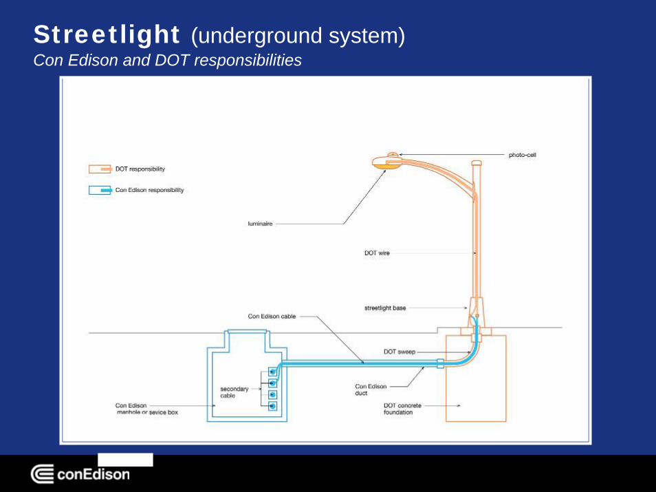
Streetlight (underground system)Con Edison and DOT responsibilities

Streetlight (underground system – base detail)

Streetlight Isolation Transformers

Streetlight Isolation Transformers
• R&D Effort
• Con Edison Purchased 5,000 units
• 600 VA Rating
• Medical Grade UL 60601-1

Isolation Transformer
Isolation Transformer TheoryNo Circuit – No Shock
120VAC
Con Edison Service
Streetlight Wiring

Streetlight SafeTap

Open Lamp Base
Look for Fuse Holders

Make Connections
Step 2) Connect Safe Tap Ground (Green) and Neutral (White) to conducting lamp base or bonding bushing
Step 4) Connect Safe Tap fuse holder (Black) to Utility Service (Black)with 30A fuse
Step 3) Connect Safe Tap fuse holder (Red) to StreetLight fuse (Black)with 15A fuse
Step 1) Disconnect existing fuse

Safe Tap in Operation
Fan connected and blowing
20A max for each outlet

Remove Safe Tap Connection
Step 3) Reconnect streetlight Connections with 15A fuse for fuse holder
Step 1)Disconnect Utility Service (black) fuse holder and Safe Tap (black) fuse holder
Step 2) Disconnect remaining Safe Tap connections
Remember to retain the Safe Tap fuse for later use!

Secure Lamp Base
6 Minutes from Start to Finish

Benefits of Streetlight Safetap®
• Provides a quick, convenient source of 120 volt temporary power from streetlights using existing fuseholders
• No need to run expensive, noisy, and polluting generators or inverters
• Increases safety by eliminating cutting and handling of bare energized conductors
• No special training required to make connections

PhaseSaver ToroidalAutotransformer

Purpose
• To safely provide three conductor service to a customer when a single phase of the underground service fails (without installing an overhead temporary service or bridging in the customer panel)

Shunt Transformer (Currently Used)
Dry Pack
15kVA - $2200 – 250 lbs
25kVA - $2450 – 350 lbs(vs. autoXFMR $600, 53 lbs)
• Can’t fit in most vehicles
• Heavy, burdensome

Single Open Phase

First TestPowering a 240V Air Conditioner from a 120V Outlet

Second TestMeter & Test Office

Third TestCompany MCC-1 Bus

Fourth TestInstallation on 21-35 35th Street

Fifth Test36,000 BTU Network AC Unit

Design Specifications
• 8000 VA
• Weight 53 lbs
• Dimensions (14” tall X 11” wide X 4.5” deep)
• Thermal Switch Autotrip with overload light
• Green lamp indicates power to unit

PhaseSaver Toroidal Autotransformer

Applications
• House Service Failures
• Con Edison Command Center Bus MCC-1
• Police Surveillance Vans / Mobile Office Trailer
• Network Transformer Air Conditioners
• Parked Refrigerated Trucks

MainsTap

Challenge
• Provide a safer method of tapping service mains for shunts and temporary power
• Reduce need to repeatedly cut and seal cable insulation

Split Bolt Connector for Shunt

Primary Live-End Cap (LEC)

If We Can Make a Primary Live End Capped Connector, Why Can’t We Make a Secondary Live End Cap?

MainsTap (tee version)

Prototype Development

MainsTap (straight version)

MainsTap (elbow version)

Removable Boots for MainsTap

Field Test

Field Test (Cont’d)

Feedback from #9 Emergency Bureau and I&A Services
• Include more ribbing surface• Develop a flexible, removable boot• Use captive nuts/check wrench clearances• Develop In-Line/Elbow Versions• Consider use with generators• Would reduce damage to system from repeated
cutting and re-sealing cable and need for Burndy®Split Bolt Connectors

Next Steps
• Standards Committee Reviews
• Lab Testing – Mechanical and Severe Heat Runs
• Training
• Issue Bulletin
• Class and Stock

Contacts - For More Information
• Al Homyk (718) 204-4175
• Don Lucia (718) 204-4412
• Randy Auclair – Electric Motion Company (860) 379-8515
• Ulrik Poulsen – Bridgeport Magnetics/Tortran (203) 335-6805

Questions?

Swimming Pools
2008 National Electrical Code Changes
Article 680.26Frank C. Lambert

Jodie Lane National Conference for Stray Voltage Detection, Mitigation, and Prevention June 5, 2007
DEFINITIONS 2005 NEC – Article 100
• Bonding (Bonded). The permanent joining of metallic parts to form an electrically conductive path that ensures electrical continuity and the capacity to conduct safely any current likely to be imposed.
• Grounded. Connected to earth or to some conducting body that serves in place of the earth.
National Electrical Code Development

Jodie Lane National Conference for Stray Voltage Detection, Mitigation, and Prevention June 5, 2007
• 1959 NEC – No mention of swimming pools.
• 1962 NEC – Article 680 – Swimming Pools • 680-7 Grounding.
– (a) All metallic conduit, piping systems, pool reinforcing steel, lighting fixtures, and the like, shall be bonded together and grounded to a common ground. The metal parts of ladders, diving boards, and their supports, shall be grounded.
• 680-8 Methods of Grounding and Bonding– (c) Non-electrical equipment required to be grounded to a common
ground in accordance with Section 680-7 shall be grounded in accordance with Article 250.
– Structural reinforcing steel may be used as a common bonding conductor for non-electrical parts where connections can be reliably made in accordance with the provisions of Article 250.
National Electrical Code Development

Jodie Lane National Conference for Stray Voltage Detection, Mitigation, and Prevention June 5, 2007
• 1975 NEC – Renumbering of Sections – Bonding and Grounding are now clearly separate issues.
• 680-22 Bonding (a) The following parts shall be bonded together:…(b) These parts shall be connected to a common bonding grid with a No. 8 solid, copper conductor and connection shall be made in accordance with Section 250-113. The common bonding grid may be any of the following.
– (1) The structural reinforcing steel of a concrete pool where the reinforcing rods are bonded together by the usual steel tie wires or the equivalent; or,
– (2) The wall of a welded metal pool; or,– (3) A solid, copper conductor not smaller than No. 8.
• 680-24 Grounding
National Electrical Code Development

Jodie Lane National Conference for Stray Voltage Detection, Mitigation, and Prevention June 5, 2007
• 1984 NEC – A very significant change / clarification added a fine print note mentioning the purpose of bonding is to eliminate voltage gradients in the pool.
• (FPN): It is not the intent of this subsection to require that the No. 8 or larger solid copper bonding conductor be extended or attached to any remote panelboard, service equipment or any electrode, but only that it be employed to eliminate voltage gradients in the pool area as prescribed.
• 1987 through 1996 – Only minor changes.
• 1999 NEC – Article 680-22. The FPN (not mandatory) added in 1984 becomes text of the code under 680-22 Bonding.
National Electrical Code Development

Jodie Lane National Conference for Stray Voltage Detection, Mitigation, and Prevention June 5, 2007
• 1999 NEC – Article 680-22. • The NEC Handbook had the following comment: The primary
purpose of bonding is to ensure that voltage gradients in the pool area are eliminated.
• The revised wording of Section 680.22 in the 1999 Code makes it clear that the No. 8 conductor is only for the elimination of the voltage gradient in the pool area and is not required to provide a path for fault current that may occur as a result of electrical equipment failure.
• 2002 NEC – Sect. 680.22 was changed to 680.26. Elimination of voltage gradients was made even stronger.
National Electrical Code Development

Jodie Lane National Conference for Stray Voltage Detection, Mitigation, and Prevention June 5, 2007
• 2005 NEC renamed Article 680.26 Equipotential Bonding
• Added part (C) Equipotential Bonding Grid to 680.26.• The equipotential common bonding grid shall extend under
paved walking surfaces for 1 m (3 ft) horizontally beyond the inside walls of the pool and shall be permitted to be any of thefollowing:(1) Structural Reinforcing Steel. The structural reinforcing steel of a concrete pool where the reinforcing rods are bonded together by the usual steel tie wires or the equivalent.(2) Bolted or Welded Metal Pools. The wall of a bolted or welded metal pool.
National Electrical Code Development

Jodie Lane National Conference for Stray Voltage Detection, Mitigation, and Prevention June 5, 2007
• 2005 NEC – Part (C) Equipotential Bonding Grid to 680.26 (Continued)
(3) Alternate Means. This system shall be permitted to be constructed as specified in (a) through (c):
– a. Materials and Connections. The grid shall be constructed of minimum 8 AWG bare solid copper conductors.
– b. Grid Structure. The equipotential bonding grid shall cover the contour of the pool and the pool deck extending 1 m (3 ft) horizontally from the inside walls of the pool. The equipotential bonding grid shall be arranged in a 300 mm (12 in.) by 300 mm (12 in.) network of conductors in a uniformly spaced perpendicular grid pattern with tolerance of 100 mm (4 in.).
– c. Securing. The below-grade grid shall be secured within or under the pool and deck media.
• Note: See Temporary Interim Agreement 05-2 for revisions to this section (exception to the bottom or sides of a nonconductive pool).
National Electrical Code Development

Jodie Lane National Conference for Stray Voltage Detection, Mitigation, and Prevention June 5, 2007
PROBLEM
• 2005 NEC Article 680.26 covers bonding of metal parts in and around swimming pools to an equipotential bonding grid.
• The article assumes that one or more of the parts are in contact with the pool water.
• Some pools do not have any bonded metal parts.
• Water- deck voltages may be significant for such a pool.

Jodie Lane National Conference for Stray Voltage Detection, Mitigation, and Prevention June 5, 2007
PROBLEM & SOLUTION ACTUAL CASE
• An employee of a member company installed a one piece drop-in pool.
• An equipotential ground grid was installed around the pool as per NEC 2005.
• 1.7 to 2 volts was measured between the pool water and ground ring.
• A copper butt plate connected to a #8 copper wire was dropped in the water (see Figure).
• Upon bonding the copper butt plate in the water with the ground grid, the voltage differential went to zero.

Jodie Lane National Conference for Stray Voltage Detection, Mitigation, and Prevention June 5, 2007
APPROACH
• NEETRAC and a member company designed a field project to measure water-deck voltages at an existing swimming pool with a history of customer complaints.
• The project mitigated the customer’s problem and allowed NEETRAC to measure water-deck voltages for various bonding scenarios in support of Article 680.26 and the proposed solution.

Jodie Lane National Conference for Stray Voltage Detection, Mitigation, and Prevention June 5, 2007
Underwater light
Hole in the deck to connect or disconnect the light from the ground
AWG #6 solid copper ground ring with seven ground rods driven at angle
Ground ring lying on the concrete
Jacuzzi with an underwater light
120-volt electrical box serving the underwater lights
Wetland
POOL DESCRIPTION

Jodie Lane National Conference for Stray Voltage Detection, Mitigation, and Prevention June 5, 2007
Pool
Jacuzzi
Buried #6 Copper Ground Ring
GroundRods
Access Hole
House
120V to40V
Source
Remote DrivenGround Rod
100 f
eet
RemoteDriven
Ground Rod V
100 feet
VNE Connect toground ring or
pool light frame
A
Neutral - WhiteGround - Bare
Line - Black
Neutral - WhiteGround - Green
Line - Black
Neutral - WhiteGround - Green
Line - BlackTo Main Pool
Light in Conduit
To JacuzziLight in Conduit
To Remote Ground- 100 feet
Disconnect Switch A- Test Connections
TestConnections
120V to 40VTransformer
CUSTOMIZED TEST SETUP TO RAISE VOLTAGE GRADIENTS
AROUND THE POOL

Jodie Lane National Conference for Stray Voltage Detection, Mitigation, and Prevention June 5, 2007
Ground Rod Ground Rod
#6 Copper Ground Ring on top of Deck
#6 Bare Copper to PoolLight Frame
Flexible PVC Conduit toSwitch A
Black, White, Green
Flexible PVC Conduit to Pool LightBlack, White, Green
ACCESS HOLE IN DECK

Jodie Lane National Conference for Stray Voltage Detection, Mitigation, and Prevention June 5, 2007
Deck
AccessHole
UnderwaterLight
Pool
Jacuzzi
Grass
House
Buried #6 Copper Ground Ring
Pool &Jacuzzi LightDisconnect
Switch
Ground Rods
#6 Copper Ground Ring on top of Deck
Deck
B1
B4
B7
C1
C4
C7
J1
J4
J7
G1
G4
G7
F1
F4
F7
E1
E4
E7
D1 D3I3 I1
H4 H1H7
A1
A4
A7
Conduits to Lights
WATER-DECK MEASUREMENT LOCATIONS AROUND THE POOL

Jodie Lane National Conference for Stray Voltage Detection, Mitigation, and Prevention June 5, 2007
THREE BONDING SCENARIOS PERTAINING TO ARTICLE 680.26 AND THE PROPOSED SOLUTION
1. Pool light and water are bonded. Ground ring and rods are not bonded.
2. Pool light, water, ground ring and rods are bonded. (2005 NEC 680.26 requirement)
3. Pool and water are not bonded but ground ring and rods are bonded. (Problem with Article 680.26 when there is no metallic bond to the pool water.)

Jodie Lane National Conference for Stray Voltage Detection, Mitigation, and Prevention June 5, 2007
0
20
40
60
80
100
120
0 2 4 6 8 10 12 14
Distance from Pool Water (Feet)
Wat
er-D
eck
Volta
ge (%
of V
ne)
Water Bonded Water & Ring Bonded Ring Bonded
Ground Ring
TEST DATA
Water-Deck Voltages along Location E

Jodie Lane National Conference for Stray Voltage Detection, Mitigation, and Prevention June 5, 2007
0
20
40
60
80
100
120
0 2 4 6 8 10 12 14
Distance from Pool Water (Feet)
Wat
er-D
eck
Vol
tage
(% o
f Vne
)
Water Bonded Water and Ring Bonded Ring Bonded
Ground Ring
TEST DATA
Water-Deck Voltages along Location F

Jodie Lane National Conference for Stray Voltage Detection, Mitigation, and Prevention June 5, 2007
0
20
40
60
80
100
120
0 2 4 6 8 10 12 14
Distance from Pool Water (Feet)
Wat
er-D
eck
Volta
ge (%
of V
ne)
Water Bonded Water & Ring Bonded Ring Bonded
TEST DATA
Water-Deck Voltages along Location G
Ground Ring

Jodie Lane National Conference for Stray Voltage Detection, Mitigation, and Prevention June 5, 2007
TEST DATA
Water-Deck Voltages along Location H
0
20
40
60
80
100
120
0 2 4 6 8 10 12 14
Distance from Pool Water (Feet)
Wat
er-D
eck
Vol
tage
(% o
f Vn
e)
Water Bonded Water & Ring Bonded Ring Bonded
Ground Ring

Jodie Lane National Conference for Stray Voltage Detection, Mitigation, and Prevention June 5, 2007
ANALYSIS
• Blue graph (only pool water bonded)• Water – deck voltage rises almost 100% within one foot
distance due to an insulated pool lining.• From one foot distance onward, the voltage practically
remains the same.• As expected the maximum voltage gradient occurred
across the insulated liner of the pool.

Jodie Lane National Conference for Stray Voltage Detection, Mitigation, and Prevention June 5, 2007
ANALYSIS (Continued)
• Red graph (pool water and ground ring bonded)• The proposed change to Article 680.26 requiring
intentional bonding of pool water.• The equipotential bonding of the water to the ground
ring reduced the water - deck voltage from 95% (Blue Graph) to 40% near the water.

Jodie Lane National Conference for Stray Voltage Detection, Mitigation, and Prevention June 5, 2007
ANALYSIS (Continued)
• Green graph (only ring bonded)• Present requirement of NEC Article 680.26. • Water-deck voltages increase to almost 100% as they
approach the ground ring.• Since the ground ring is located at a distance of 11.5’
from the water, the voltage gradients near the water are not significant in this investigation.
• Voltages near the water will increase significantly if the ground ring or a hand rail were to be located near the water.

Jodie Lane National Conference for Stray Voltage Detection, Mitigation, and Prevention June 5, 2007
0
20
40
60
80
100
120
0 0.2 0.4 0.6 0.8 1 1.2
Distance from Pool Water (Feet)
Wat
er-H
andr
ail V
olta
ge (%
of V
nre)
Only Handrail Bonded (Present NEC 680.26)Water and Handrail Bonded (Proposed Change)
PROJECTED WATER-HANDRAIL VOLTAGES BASED ON
MEASURED DATA

Jodie Lane National Conference for Stray Voltage Detection, Mitigation, and Prevention June 5, 2007
Insert a new Section 680.26(C) as follows:680.26 (C) Pool Water
An intentional bond of a minimum conductive surface area of 5806 mm2 (9 in2) shall be installed in contact with the pool water. This bond shall be permitted to consist of parts that are required to be bonded in 680.26(B).
Renumber the present Sections sequentially from (C) to (D), (D) to (E), and (E) to (F).
NEC 680.26 PROPOSED CHANGE
ACCEPTED BY CODE PANEL 17 FOR INCLUSION IN 2008 NEC CODE

2007 Jodie Lane National Conference for Stray Voltage Detection,2007 Jodie Lane National Conference for Stray Voltage Detection, Mitigation & PreventionMitigation & Prevention
IEEE Working Group on IEEE Working Group on Voltages at Publicly and Voltages at Publicly and
Privately Accessible LocationsPrivately Accessible Locations
June 5June 5thth 20072007Doug Dorr Doug Dorr –– EPRIEPRI

2007 Jodie Lane National Conference for Stray Voltage Detection,2007 Jodie Lane National Conference for Stray Voltage Detection, Mitigation & PreventionMitigation & Prevention
IEEE Working GroupIEEE Working Group

2007 Jodie Lane National Conference for Stray Voltage Detection,2007 Jodie Lane National Conference for Stray Voltage Detection, Mitigation & PreventionMitigation & Prevention
IEEE Working GroupIEEE Working Group

2007 Jodie Lane National Conference for Stray Voltage Detection,2007 Jodie Lane National Conference for Stray Voltage Detection, Mitigation & PreventionMitigation & Prevention

2007 Jodie Lane National Conference for Stray Voltage Detection,2007 Jodie Lane National Conference for Stray Voltage Detection, Mitigation & PreventionMitigation & Preventionwgovapapal
OUTLINE DRAFT
Trial Use Guide for Assessing Voltages at Publicly and Privately Accessible Locations
From the Standards Board Operations Manual:
•Guides: documents in which alternative approaches to good practice are suggested but no clear-cut recommendations are made.
•Trial-Use documents: publications that are effective for not more than two years.

2007 Jodie Lane National Conference for Stray Voltage Detection,2007 Jodie Lane National Conference for Stray Voltage Detection, Mitigation & PreventionMitigation & Prevention
P1695 PURPOSE
There is presently no industry wide guide or standard that describes the variety of publicly and privately accessible voltages resulting from the delivery and use of electrical energy. This guide will help dispel misinformation surrounding this topic and enhance public safety.
wgovapapal

2007 Jodie Lane National Conference for Stray Voltage Detection,2007 Jodie Lane National Conference for Stray Voltage Detection, Mitigation & PreventionMitigation & Prevention
P1695 SCOPE
This guide addresses the normal and abnormal voltages that exist at publicly and privately accessible locations as a result of the delivery and use of electrical energy (often referred to as stray voltage). It focuses primarily on the presence of power frequency related voltages, and discusses definitions, causes, impacts, testing techniques, mitigation strategies, and hazard levels.
wgovapapal

2007 Jodie Lane National Conference for Stray Voltage Detection,2007 Jodie Lane National Conference for Stray Voltage Detection, Mitigation & PreventionMitigation & Prevention
IEEE Working GroupIEEE Working Group
ScopeScopePurposePurpose

2007 Jodie Lane National Conference for Stray Voltage Detection,2007 Jodie Lane National Conference for Stray Voltage Detection, Mitigation & PreventionMitigation & Prevention
IEEE Working GroupIEEE Working Group
ScopeScopePurposePurpose

2007 Jodie Lane National Conference for Stray Voltage Detection,2007 Jodie Lane National Conference for Stray Voltage Detection, Mitigation & PreventionMitigation & Prevention
IEEE Working GroupIEEE Working Group
ScopeScopePurposePurpose

2007 Jodie Lane National Conference for Stray Voltage Detection,2007 Jodie Lane National Conference for Stray Voltage Detection, Mitigation & PreventionMitigation & Prevention
IEEE Working GroupIEEE Working Group
ScopeScopePurposePurpose

2007 Jodie Lane National Conference for Stray Voltage Detection,2007 Jodie Lane National Conference for Stray Voltage Detection, Mitigation & PreventionMitigation & Prevention
A Few Important Points(Based On Working Group Discussions To Date)
wgovapapal
There are publicly accessible voltages related to normal system operation that must be present, and there are publicly accessible voltages related to abnormal system operation that should not be present. These are two very different things that should be defined and discussed separately.
Human and animal exposure to conducted current is well understood. We want the reader to learn something about the science behind existing exposure standards; where to find, and how to apply these standards. This is necessary so that informed decisions can be made regarding the degree of hazard that exists and what, if anything, should be done about it.
We want to provide the reader with the knowledge and tools necessary to make meaningful measurements. This will enable identification of sources and, if necessary, aid in selection of appropriate mitigation alternatives.

2007 Jodie Lane National Conference for Stray Voltage Detection,2007 Jodie Lane National Conference for Stray Voltage Detection, Mitigation & PreventionMitigation & Prevention
General ObjectivesGeneral ObjectivesTo facilitate a better understanding of the causes, To facilitate a better understanding of the causes, investigation procedures and mitigation options for investigation procedures and mitigation options for voltage concerns at publicly and privately accessible voltage concerns at publicly and privately accessible locationslocations–– Human and animal physiological responses to currents through Human and animal physiological responses to currents through
the bodythe body–– Identification of the various sources of stray voltages to incluIdentification of the various sources of stray voltages to include de
induced voltages on to metallic objects, grounded neutral induced voltages on to metallic objects, grounded neutral conductors, and high impedance power system and load faultsconductors, and high impedance power system and load faults
–– Standardized measurement protocols and procedures to Standardized measurement protocols and procedures to characterize the various sources and types of stray voltagecharacterize the various sources and types of stray voltage
–– Proposed voltage levels for the various situations (pools, Proposed voltage levels for the various situations (pools, pipelines, manhole covers etc.) upon which remedial actions pipelines, manhole covers etc.) upon which remedial actions should be pursuedshould be pursued

2007 Jodie Lane National Conference for Stray Voltage Detection,2007 Jodie Lane National Conference for Stray Voltage Detection, Mitigation & PreventionMitigation & Preventionwgovapapal
Outline Draft (05/17/2007)IEEE Trial Use Guide for Assessing Voltages at Publicly and Privately
Accessible Locations
1. Overview (Required)
2. Normative References (Required)
3. Definitions/Acronyms/Abbreviations (Required)
4. General Discussion
5. Human and Animal Sensitivity to Conducted Current5.1 Sensitivity in terms of voltage exposure
6. Publicly and Privately Accessible Voltages Related to Abnormal System Operation (“Contact Voltage”)6.1 General6.2 Contact Voltage Sources6.3 Contact Voltage Investigation
6.3.1 Test and Measurement Equipment6.3.2 Investigation Protocol
6.4 Contact Voltage Mitigation6.5 Case Studies

2007 Jodie Lane National Conference for Stray Voltage Detection,2007 Jodie Lane National Conference for Stray Voltage Detection, Mitigation & PreventionMitigation & Preventionwgovapapal
7. Publicly and Privately Accessible Voltages Related to Normal System Operation ( (“Stray Voltage”)
7.1 General7.2 Stray Voltage Sources
7.2.1 Return Current7.2.2 Induced Current
7.3 Stray Voltage Investigation7.3.1 Test and Measurement Equipment7.3.2 Investigation Protocol
7.3.2.1 Confined Livestock7.3.2.2 Swimming Pools7.3.3.3 Outdoor and Basement Showers
7.4 Stray Voltage Mitigation7.5 Case Studies
8. Previously Established Voltage Exposure Standards
9. Existing Regulation
Annex A: Flow Charts
Annex B: Sample Data Collection Forms
Annex C: ???

2007 Jodie Lane National Conference for Stray Voltage Detection,2007 Jodie Lane National Conference for Stray Voltage Detection, Mitigation & PreventionMitigation & Preventionwgovapapal
Outline Draft (05/17/2007)
IEEE Trial Use Guide for Assessing Voltages at Publicly and Privately Accessible Locations
1. Overview (Required)
2. Normative References (Required)
3. Definitions/Acronyms/Abbreviations (Required)
4. General Discussion
Scope and Purpose of the Guide
Documents necessary to understand and use the Guide (e.g. USDA Handbook 696)
Reasons for confusion surrounding the issue, some amount of measurable voltage will always be present, contact voltage v. stray voltage, sources are both primary (utility) and secondary (customer), grounded v.ungrounded systems, etc.

2007 Jodie Lane National Conference for Stray Voltage Detection,2007 Jodie Lane National Conference for Stray Voltage Detection, Mitigation & PreventionMitigation & Preventionwgovapapal
Outline Draft (05/17/2007) Continued
IEEE Trial Use Guide for Assessing Voltages at Publicly and Privately Accessible Locations
5. Human and Animal Sensitivity to Conducted Current
5.1 Sensitivity in terms of voltage exposure
Research summary, nerve stimulation model discussion, factors affecting sensitivity, sensitivity versus frequency and/or duration of exposure, people versus animals, etc.
Characteristics and importance of the exposure circuit (e.g. source impedance, contact impedance, body impedance, etc.), why it’s difficult to create a voltage exposure standard, etc.

2007 Jodie Lane National Conference for Stray Voltage Detection,2007 Jodie Lane National Conference for Stray Voltage Detection, Mitigation & PreventionMitigation & Preventionwgovapapal
6. Publicly and Privately Accessible Voltages Related to Abnormal System Operation (“Contact Voltage”)
Outline Draft (05/17/2007) Continued
IEEE Trial Use Guide for Assessing Voltages at Publicly and Privately Accessible Locations
6.1 GeneralPotentially hazardous nature of contact voltage, degree of hazard dependent on exposure circuit not measurement circuit, number ofincidents (i.e. putting the issue in perspective), existing proactive programs, etc.
6.2 Contact Voltage Sources
Fault current (i.e. shorts and opens), fault current availability, insulation degradation, wiring errors, broken conductors, voltages induced during fault conditions, etc.

2007 Jodie Lane National Conference for Stray Voltage Detection,2007 Jodie Lane National Conference for Stray Voltage Detection, Mitigation & PreventionMitigation & Preventionwgovapapal
6.3 Contact Voltage Investigation
Outline Draft (05/17/2007) Continued
IEEE Trial Use Guide for Assessing Voltages at Publicly and Privately Accessible Locations
6.3.1 Test and Measurement EquipmentElectric field detection (e.g. proximity detectors, mobile platforms, etc.), multi-meters, load resistors, safety gear, etc.
6.3.2 Investigation Protocol Safety precautions, understanding remote earth, measurement location, measurement technique, data analysis, false positives,etc.
6.4 Contact Voltage MitigationInsulation failure, wiring errors, open conductors, etc.
6.5 Case Studies
Street light, manhole, etc.

2007 Jodie Lane National Conference for Stray Voltage Detection,2007 Jodie Lane National Conference for Stray Voltage Detection, Mitigation & PreventionMitigation & Preventionwgovapapal
Outline Draft (05/17/2007) Continued
IEEE Trial Use Guide for Assessing Voltages at Publicly and Privately Accessible Locations
7. Publicly and Privately Accessible Voltages Related to Normal System Operation (“Stray Voltage”)
7.1 GeneralHistorically considered a nuisance voltage. Generally associated with animal exposures, swimming pool & shower shocks. Primary (utility) and secondary (customer) sources. Harmonics, transients, etc.
7.2 Stray Voltage Sources
7.2.1 Return CurrentSystems with a neutral conductor, systems without a neutral conductor, SWER, etc.
7.2.2 Induced Current Transmission Source, Primary Source, Secondary Source, etc.

2007 Jodie Lane National Conference for Stray Voltage Detection,2007 Jodie Lane National Conference for Stray Voltage Detection, Mitigation & PreventionMitigation & Preventionwgovapapal
Outline Draft (05/17/2007) Continued
IEEE Trial Use Guide for Assessing Voltages at Publicly and Privately Accessible Locations
7.3 Stray Voltage Investigation
7.3.1 Test and Measurement EquipmentRecording devices, load boxes, copper plates, etc.
7.3.2 Investigation Protocol
7.3.2.1 Confined Livestock
7.3.2.2 Swimming Pools
7.3.3.3 Outdoor and Basement Showers
7.4 Stray Voltage Mitigation Bad neutral connections, undersized conductors, poor grounding, phase balance, system voltage, etc.
7.5 Case Studies

2007 Jodie Lane National Conference for Stray Voltage Detection,2007 Jodie Lane National Conference for Stray Voltage Detection, Mitigation & PreventionMitigation & Preventionwgovapapal
Outline Draft (05/17/2007) Continued
IEEE Trial Use Guide for Assessing Voltages at Publicly and Privately Accessible Locations
8. Previously Established Voltage Exposure Standards
IEEE, IEC, NEC, etc.
9. Existing Regulation
Wisconsin, Idaho, Michigan, New York, etc.
Annex A: Flow Charts
Annex B: Sample Data Collection Forms
Annex C: ???

2007 Jodie Lane National Conference for Stray Voltage Detection,2007 Jodie Lane National Conference for Stray Voltage Detection, Mitigation & PreventionMitigation & Prevention
IEEE P1695 WG Next MeetingIEEE P1695 WG Next Meeting

2007 Jodie Lane National Conference for Stray Voltage Detection,2007 Jodie Lane National Conference for Stray Voltage Detection, Mitigation & PreventionMitigation & Prevention
EPRI Program 128.004EPRI Program 128.004Elevated NEV and Urban Stray Elevated NEV and Urban Stray Voltage Concerns in Distribution Voltage Concerns in Distribution
Systems Research UpdateSystems Research Update
June 5June 5thth 20072007Doug Dorr Doug Dorr –– EPRIEPRI

2007 Jodie Lane National Conference for Stray Voltage Detection,2007 Jodie Lane National Conference for Stray Voltage Detection, Mitigation & PreventionMitigation & Prevention
P128.004 EleP128.004 Elevated NEV and vated NEV and Urban Stray Voltage ConcernsUrban Stray Voltage Concerns
This project has been ongoing This project has been ongoing since 2004 to address gaps in the since 2004 to address gaps in the research and technology transfer research and technology transfer In 2007 the project provides In 2007 the project provides sponsors with informational sponsors with informational support (for regulators and support (for regulators and customers)customers)
–– Standardized measurement Standardized measurement protocols (best practices and protocols (best practices and more accurate documentation)more accurate documentation)
–– Investigation support (reduces Investigation support (reduces trouble crews time)trouble crews time)
–– Case studies (helps investigators Case studies (helps investigators with location of problem and with location of problem and solution optionssolution options
–– Industry outreach Industry outreach –– IEEE, Pool IEEE, Pool and spa and spa mfgrsmfgrs. association . association (helping to promote (helping to promote standardization and better standardization and better grounding and bonding practices)grounding and bonding practices)

2007 Jodie Lane National Conference for Stray Voltage Detection,2007 Jodie Lane National Conference for Stray Voltage Detection, Mitigation & PreventionMitigation & Prevention
Five Focus AreasFive Focus Areas–– Measurement of Contact VoltageMeasurement of Contact Voltage–– Modeling and SimulationModeling and Simulation–– Diagnostics and MitigationDiagnostics and Mitigation–– Mitigation Devices and Condition AssessmentMitigation Devices and Condition Assessment–– Regulatory Informational Support and Regulatory Informational Support and
Technology TransferTechnology Transfer

2007 Jodie Lane National Conference for Stray Voltage Detection,2007 Jodie Lane National Conference for Stray Voltage Detection, Mitigation & PreventionMitigation & Prevention
Specific Focus Area NeedsSpecific Focus Area Needs–– Measurement of Contact VoltageMeasurement of Contact Voltage
Are the investigative tools we use today adequate?Are the investigative tools we use today adequate?What are some areas of opportunity for new tool development?What are some areas of opportunity for new tool development?Can we use existing monitoring devices to support early detectioCan we use existing monitoring devices to support early detection n efforts? efforts?
–– Modeling and SimulationModeling and SimulationWhat parameters impact contact voltages? Which are most What parameters impact contact voltages? Which are most important?important?Is it possible to model entire distribution systems?Is it possible to model entire distribution systems?What kinds of accuracies should be expectedWhat kinds of accuracies should be expected
–– Diagnostics and MitigationDiagnostics and MitigationBetter ways to quickly identify the Better ways to quickly identify the source(ssource(s))Prioritization based on the type of contact voltage concernPrioritization based on the type of contact voltage concernBetter likelihood the correct mitigation solutions get appliedBetter likelihood the correct mitigation solutions get applied

2007 Jodie Lane National Conference for Stray Voltage Detection,2007 Jodie Lane National Conference for Stray Voltage Detection, Mitigation & PreventionMitigation & Prevention
Specific Focus Area NeedsSpecific Focus Area Needs–– New Mitigation Techniques and Condition New Mitigation Techniques and Condition
AssessmentsAssessmentsBased on the Based on the source(ssource(s))
–– Are there alternative mitigation solutionsAre there alternative mitigation solutions–– What is considered What is considered ““TypicalTypical”” or or ““NormalNormal””??
–– Regulatory Recommendations and Information Regulatory Recommendations and Information TransferTransfer
Accurate and factual information for informed Accurate and factual information for informed decision makingdecision makingClear understanding of the differences in contact Clear understanding of the differences in contact scenarios and the objective: (aversion, injury due scenarios and the objective: (aversion, injury due to startle reaction, let go thresholds, etc..)to startle reaction, let go thresholds, etc..)

2007 Jodie Lane National Conference for Stray Voltage Detection,2007 Jodie Lane National Conference for Stray Voltage Detection, Mitigation & PreventionMitigation & Prevention
P128.004 EleP128.004 Elevated NEV and vated NEV and Urban Stray Voltage ConcernsUrban Stray Voltage ConcernsEPRI Sponsored Project Website EPRI Sponsored Project Website –– 2007 Updated Version 2007 Updated Version will be on line August 2007will be on line August 2007Provides information to sponsors and the public to promote Provides information to sponsors and the public to promote credible and unbiased information on the subject mattercredible and unbiased information on the subject matter

2007 Jodie Lane National Conference for Stray Voltage Detection,2007 Jodie Lane National Conference for Stray Voltage Detection, Mitigation & PreventionMitigation & Prevention
P128.004 EleP128.004 Elevated NEV and vated NEV and Urban Stray Voltage ConcernsUrban Stray Voltage Concerns
Key results from 2006Key results from 2006–– Final report describes Final report describes
software, procedures software, procedures and examples on how and examples on how different changes to different changes to resistances, resistances, impedances and impedances and capacitor bank capacitor bank configurations impact configurations impact NEV levelsNEV levels
–– FindingsFindings: With careful : With careful field measurement field measurement verification, we can verification, we can expect accurate expect accurate (plus/minus 10%) (plus/minus 10%) modeling results to modeling results to evaluate distribution evaluate distribution level parametric level parametric
Project 2007 ObjectivesProject 2007 Objectives–– Evaluate sponsor selected Evaluate sponsor selected
measurement equipment or measurement equipment or mitigation devices to support a mitigation devices to support a comprehensive NEV and Urban comprehensive NEV and Urban Stray Voltage Investigators Stray Voltage Investigators ToolboxToolbox
–– Via Website Via Website -- Provide Provide comprehensive and technically comprehensive and technically accurate materials to support accurate materials to support investigations and understanding investigations and understanding of mitigation optionsof mitigation options
–– Support ongoing IEEE Support ongoing IEEE ““contact contact voltagevoltage”” standards effortsstandards efforts
–– Provide credible data on typical Provide credible data on typical NEV levels for feeders and circuits NEV levels for feeders and circuits to better define regulator to better define regulator expectations regarding grounded expectations regarding grounded neutral circuitsneutral circuits

2007 Jodie Lane National Conference for Stray Voltage Detection,2007 Jodie Lane National Conference for Stray Voltage Detection, Mitigation & PreventionMitigation & Prevention
P128.004 EleP128.004 Elevated NEV and vated NEV and Urban Stray Voltage ConcernsUrban Stray Voltage Concerns
Task 1 Task 1 –– Evaluate measurement Evaluate measurement and mitigation equipmentand mitigation equipment–– Testing will be Testing will be
accomplished in accomplished in controlled laboratory controlled laboratory setting or at field site setting or at field site depending on the depending on the devicedevice
–– Deliverables will be Deliverables will be technically accurate technically accurate application guidance application guidance and expectations and expectations documentsdocuments
–– Some field sites may Some field sites may b l t d t l tb l t d t l t
Task 2 Task 2 –– WebsiteWebsite–– Update existing information to Update existing information to
reflect 2007 level of reflect 2007 level of understandingunderstanding
–– Provide more application Provide more application guidance on use of test and guidance on use of test and measurement equipmentmeasurement equipment
–– Provide more application Provide more application guidance on mitigation solutionsguidance on mitigation solutions
Task 3 Task 3 –– NEV levels technical NEV levels technical assessmentassessment–– Field measurementsField measurements–– Controlled laboratory Controlled laboratory
measurements on measurements on representative circuitsrepresentative circuits

2007 Jodie Lane National Conference for Stray Voltage Detection,2007 Jodie Lane National Conference for Stray Voltage Detection, Mitigation & PreventionMitigation & Prevention
ConclusionsConclusionsThe EPRI Efforts and the IEEE Efforts are The EPRI Efforts and the IEEE Efforts are closely aligned in terms of developing closely aligned in terms of developing consistent and repeatable investigation consistent and repeatable investigation and remediation guidelinesand remediation guidelinesEPRIEPRI’’ss efforts are intended to supplement efforts are intended to supplement but not duplicate any of the other researchbut not duplicate any of the other researchThe subject continues to gain support and The subject continues to gain support and the number of participating electric service the number of participating electric service providers has increased significantlyproviders has increased significantly

2007 Jodie Lane National Conference for Stray Voltage Detection,2007 Jodie Lane National Conference for Stray Voltage Detection, Mitigation & PreventionMitigation & Prevention
Roundtable DiscussionRoundtable Discussion
Issues and Potential FollowIssues and Potential Follow--on Actionson ActionsJune 5June 5thth 20072007
Frank Doherty Frank Doherty –– Session ModeratorSession Moderator

2007 Jodie Lane National Conference for Stray Voltage Detection,2007 Jodie Lane National Conference for Stray Voltage Detection, Mitigation & PreventionMitigation & Prevention
Roundtable FormatRoundtable Format1.1. ~20 minutes each (dependent on number)~20 minutes each (dependent on number)2.2. One person will briefly describe the concernOne person will briefly describe the concern3.3. Participants will provide:Participants will provide:
1.1. Specific issuesSpecific issues2.2. State of the art and present published workState of the art and present published work3.3. What others are doingWhat others are doing4.4. What is neededWhat is needed
4.4. Moderator will summarize actions & followModerator will summarize actions & follow--upup

2007 Jodie Lane National Conference for Stray Voltage Detection,2007 Jodie Lane National Conference for Stray Voltage Detection, Mitigation & PreventionMitigation & Prevention
Discussion TopicsDiscussion Topics
1.1. Degraded concentric neutralsDegraded concentric neutrals2.2. Transmission structure testingTransmission structure testing3.3. New test and measurement toolsNew test and measurement tools4.4. Items from participantsItems from participants

2007 Jodie Lane National Conference for Stray Voltage Detection,2007 Jodie Lane National Conference for Stray Voltage Detection, Mitigation & PreventionMitigation & Prevention
RoundtableRoundtable DiscussionDiscussion
Degraded Concentric Degraded Concentric NeutralsNeutrals

2007 Jodie Lane National Conference for Stray Voltage Detection,2007 Jodie Lane National Conference for Stray Voltage Detection, Mitigation & PreventionMitigation & Prevention
Elevated Neutral Elevated Neutral -- to to -- Earth VoltageEarth Voltage
Forest Bigenho Forest Bigenho –– Snohomish PUD Snohomish PUD [email protected]@snopud.com
June 5, 2007June 5, 2007

2007 Jodie Lane National Conference for Stray Voltage Detection,2007 Jodie Lane National Conference for Stray Voltage Detection, Mitigation & PreventionMitigation & Prevention
Presentation OverviewPresentation Overview
Utility BackgroundUtility BackgroundSystem ConfigurationSystem ConfigurationProblemProblemTroubleshootingTroubleshootingResolutionResolution

2007 Jodie Lane National Conference for Stray Voltage Detection,2007 Jodie Lane National Conference for Stray Voltage Detection, Mitigation & PreventionMitigation & Prevention
PUD Service TerritoryPUD Service Territory
Headquarters:Headquarters:2320 California Street, Everett, WA 982012320 California Street, Everett, WA 98201
(Mailing Address: PO Box 1107, Everett, WA 98206(Mailing Address: PO Box 1107, Everett, WA 98206--1107)1107)

2007 Jodie Lane National Conference for Stray Voltage Detection,2007 Jodie Lane National Conference for Stray Voltage Detection, Mitigation & PreventionMitigation & Prevention
Electric SystemElectric SystemService Area:Service Area: 2,200 square miles, including all of Snohomish 2,200 square miles, including all of Snohomish County and Camano IslandCounty and Camano Island
2006 Electrical Service Connections:2006 Electrical Service Connections: 7,7607,760
2006 Average Number of Employees:2006 Average Number of Employees: 900900
2006 Energy Sales:2006 Energy Sales: 8,167,281 megawatt8,167,281 megawatt--hourshours
2006 Electric System Operating Revenues:2006 Electric System Operating Revenues: $582,847,000$582,847,000
Generating Capacity:Generating Capacity: 164 megawatts (Jackson Project, Everett 164 megawatts (Jackson Project, Everett Cogeneration Project)Cogeneration Project)
Residential Rate:Residential Rate:–– 7.77.7¢¢ per kilowattper kilowatt--hour (April 1 hour (April 1 -- September 30)September 30)–– 8.08.0¢¢ per kilowattper kilowatt--hour (October 1 hour (October 1 -- March 30)March 30)

2007 Jodie Lane National Conference for Stray Voltage Detection,2007 Jodie Lane National Conference for Stray Voltage Detection, Mitigation & PreventionMitigation & Prevention
PUD Customer CategoriesPUD Customer Categories

2007 Jodie Lane National Conference for Stray Voltage Detection,2007 Jodie Lane National Conference for Stray Voltage Detection, Mitigation & PreventionMitigation & Prevention
Operating VoltagesOperating Voltages
Transmission 115 kVTransmission 115 kVDistribution 12.47 kVDistribution 12.47 kVOverhead/Underground Radial & Looped RadialOverhead/Underground Radial & Looped Radial
OH/UG Secondary Service voltageOH/UG Secondary Service voltage120/240 Volt Single Phase120/240 Volt Single Phase240/480 Volt Single Phase (UG max 100kVA)240/480 Volt Single Phase (UG max 100kVA)120/208 Volt Single/Three Phase 120/208 Volt Single/Three Phase 277/480 Volt three Phase Wye277/480 Volt three Phase Wye

2007 Jodie Lane National Conference for Stray Voltage Detection,2007 Jodie Lane National Conference for Stray Voltage Detection, Mitigation & PreventionMitigation & Prevention
Underground DistributionUnderground Distribution
Direct Direct BurriedBurried ~ ~ 800 miles800 miles (Early 60(Early 60’’s s –– Late 80Late 80’’s)s)
Conduit/Ducts ~Conduit/Ducts ~2400 miles2400 miles (PVC/Fiberglass/Steel)(PVC/Fiberglass/Steel)
Conductor Insulation Types: Conductor Insulation Types: XLPE XLPE TRXLPE TRXLPE (1985 to present)(1985 to present)
EPR EPR (1000kcmil only)(1000kcmil only)
Conductor SplicingConductor SplicingStraight Splice onlyStraight Splice only……Junction Boxes used for 3 and 4 Junction Boxes used for 3 and 4
way conductor configurations.way conductor configurations.

2007 Jodie Lane National Conference for Stray Voltage Detection,2007 Jodie Lane National Conference for Stray Voltage Detection, Mitigation & PreventionMitigation & Prevention
UG CABLE PROGRAMUG CABLE PROGRAM
Development/Design for new construction/area Development/Design for new construction/area development (2000 to 2006 growth rate at 11%) development (2000 to 2006 growth rate at 11%) Managing 800 miles of directManaging 800 miles of direct--buried distribution buried distribution cablecablePrioritizing cable rePrioritizing cable re--conductor/cable conductor/cable rejuvenationrejuvenation(cable rejuvenation via silicone injection)(cable rejuvenation via silicone injection)Yearly goal: Replace 20 miles of UG conductorYearly goal: Replace 20 miles of UG conductor
Rejuvenate 40 miles of UG conductor Rejuvenate 40 miles of UG conductor

2007 Jodie Lane National Conference for Stray Voltage Detection,2007 Jodie Lane National Conference for Stray Voltage Detection, Mitigation & PreventionMitigation & Prevention
Elevated Neutral to Earth Voltage Elevated Neutral to Earth Voltage (NEV) (NEV)
Condition at (campingCondition at (camping--park) revealed high (NEV) values park) revealed high (NEV) values (12.47/7.2 kV (12.47/7.2 kV –– Single phase dist.)Single phase dist.)Conductor Direct Buried unjacketed XLPE Conductor Direct Buried unjacketed XLPE ––30+ Svc Years30+ Svc YearsTDR (Time Domain Reflectometer) demonstrated TDR (Time Domain Reflectometer) demonstrated bad/open concentric neutrals.bad/open concentric neutrals.Poor area grounding Poor area grounding Seasonal LoadingSeasonal Loading

2007 Jodie Lane National Conference for Stray Voltage Detection,2007 Jodie Lane National Conference for Stray Voltage Detection, Mitigation & PreventionMitigation & Prevention
Camp Ground/Trailer Camp Ground/Trailer ParkPark
TDR plot of underground cable with level 3 neutral corrosion

2007 Jodie Lane National Conference for Stray Voltage Detection,2007 Jodie Lane National Conference for Stray Voltage Detection, Mitigation & PreventionMitigation & Prevention
TroubleshootingTroubleshooting
Research utility records and maps Research utility records and maps (when & what is installed)(when & what is installed)
Validate complaint (voltmeter between shower Validate complaint (voltmeter between shower head/drain)head/drain)Inspect customer service terminations/groundsInspect customer service terminations/groundsInspect utility transformer grounding and concentric Inspect utility transformer grounding and concentric neutral cable conditionsneutral cable conditionsReview loading (what loads applied) rule out harmonicsReview loading (what loads applied) rule out harmonicsPerform Time Domain Reflectometer test.Perform Time Domain Reflectometer test.Perform Conductor to Soil Potential test.Perform Conductor to Soil Potential test.Sent Soil samples to Lab Sent Soil samples to Lab (help determine rate of corrosion)(help determine rate of corrosion)

2007 Jodie Lane National Conference for Stray Voltage Detection,2007 Jodie Lane National Conference for Stray Voltage Detection, Mitigation & PreventionMitigation & Prevention
Underground Cable Underground Cable TDR FeedTDR Feed
TDR plot of underground cable with level 3 neutral corrosion

2007 Jodie Lane National Conference for Stray Voltage Detection,2007 Jodie Lane National Conference for Stray Voltage Detection, Mitigation & PreventionMitigation & Prevention
Underground Cable Underground Cable TDR ReflectionsTDR Reflections
TDR plot of underground cable with splice –no neutral corrosion

2007 Jodie Lane National Conference for Stray Voltage Detection,2007 Jodie Lane National Conference for Stray Voltage Detection, Mitigation & PreventionMitigation & Prevention
Underground Cable Underground Cable TDR ReflectionsTDR Reflections
TDR plot of underground cable with level 3 neutral corrosion

2007 Jodie Lane National Conference for Stray Voltage Detection,2007 Jodie Lane National Conference for Stray Voltage Detection, Mitigation & PreventionMitigation & Prevention
Conductor to Soil Potential Conductor to Soil Potential TestTest
TDR plot of underground cable with level 3 neutral corrosion

2007 Jodie Lane National Conference for Stray Voltage Detection,2007 Jodie Lane National Conference for Stray Voltage Detection, Mitigation & PreventionMitigation & Prevention
Pot Hole Pot Hole -- Soil Snap ShotSoil Snap Shot
TDR plot of underground cable with level 3 neutral corrosion

2007 Jodie Lane National Conference for Stray Voltage Detection,2007 Jodie Lane National Conference for Stray Voltage Detection, Mitigation & PreventionMitigation & Prevention
Planned Action/ResolutionPlanned Action/Resolution
Identify cables with deteriorated neutralsIdentify cables with deteriorated neutralsReplace with TRXLPE jacketed type cable in conduitReplace with TRXLPE jacketed type cable in conduitInstall new earth grounding system at each vault Install new earth grounding system at each vault ––((grounds will be enhanced due to very rocky soil)grounds will be enhanced due to very rocky soil)
Possibly install corrosion mitigation system for remaining Possibly install corrosion mitigation system for remaining cable cable –– cathodic protection.cathodic protection.Remaining cable to be replaced on a planned scheduleRemaining cable to be replaced on a planned schedule

2007 Jodie Lane National Conference for Stray Voltage Detection,2007 Jodie Lane National Conference for Stray Voltage Detection, Mitigation & PreventionMitigation & Prevention
QuestionsQuestions
What are other utilities doing for the following:What are other utilities doing for the following:
Neutral Corrosion identificationNeutral Corrosion identificationCorrosion mitigation Corrosion mitigation –– cathodic protectioncathodic protectionCable ReplacementCable ReplacementCable InjectionCable InjectionComprehensive underground cable management programComprehensive underground cable management programPrioritizing cables for injection and replacement Prioritizing cables for injection and replacement

2007 Jodie Lane National Conference for Stray Voltage Detection,2007 Jodie Lane National Conference for Stray Voltage Detection, Mitigation & PreventionMitigation & Prevention
Degraded Concentric NeutralsDegraded Concentric Neutrals
1.1. Specific issuesSpecific issues2.2. State of the art and present published workState of the art and present published work3.3. What others are doingWhat others are doing4.4. What is neededWhat is needed

2007 Jodie Lane National Conference for Stray Voltage Detection,2007 Jodie Lane National Conference for Stray Voltage Detection, Mitigation & PreventionMitigation & Prevention
RoundtableRoundtable DiscussionDiscussion
Transmission Structures Transmission Structures Testing for Stray VoltageTesting for Stray Voltage

2007 Jodie Lane National Conference for Stray Voltage Detection,2007 Jodie Lane National Conference for Stray Voltage Detection, Mitigation & PreventionMitigation & Prevention
Transmission Transmission StructuresStructures

2007 Jodie Lane National Conference for Stray Voltage Detection,2007 Jodie Lane National Conference for Stray Voltage Detection, Mitigation & PreventionMitigation & Prevention
Transmission StructuresTransmission StructuresTransmission lines present several different Transmission lines present several different
configurations for towers, overhead wires and configurations for towers, overhead wires and tower footings (counterpoise). tower footings (counterpoise).
The different configurations will establish different The different configurations will establish different responses of the system; whether stressed by responses of the system; whether stressed by lightning, or steady state in conjunction with lightning, or steady state in conjunction with other linear or spot structures, such as electric other linear or spot structures, such as electric distribution lines (OH or UG), gas mains, distribution lines (OH or UG), gas mains, fences etc. fences etc.

2007 Jodie Lane National Conference for Stray Voltage Detection,2007 Jodie Lane National Conference for Stray Voltage Detection, Mitigation & PreventionMitigation & Prevention
Transmission StructuresTransmission Structures
1.1. Specific issuesSpecific issues2.2. State of the art and present published workState of the art and present published work3.3. What others are doingWhat others are doing4.4. What is neededWhat is needed

2007 Jodie Lane National Conference for Stray Voltage Detection,2007 Jodie Lane National Conference for Stray Voltage Detection, Mitigation & PreventionMitigation & Prevention
RoundtableRoundtable DiscussionDiscussion
Development of New ToolsDevelopment of New ToolsTo Diagnose and ResolveTo Diagnose and ResolveStray Voltage Stray Voltage Source(sSource(s))

2007 Jodie Lane National Conference for Stray Voltage Detection,2007 Jodie Lane National Conference for Stray Voltage Detection, Mitigation & PreventionMitigation & Prevention
New Tools IssuesNew Tools Issues
Different SourcesDifferent Sources–– Magnetically CoupledMagnetically Coupled–– Faulted ObjectsFaulted Objects–– Multi Grounded NeutralsMulti Grounded NeutralsDifferent Levels of ConcernDifferent Levels of Concern–– Aversion (perception)Aversion (perception)–– Injury (startle reaction)Injury (startle reaction)–– Injury (let go threshold)Injury (let go threshold)

2007 Jodie Lane National Conference for Stray Voltage Detection,2007 Jodie Lane National Conference for Stray Voltage Detection, Mitigation & PreventionMitigation & Prevention
TodayToday’’s Situations SituationLots of tools from pen lights to data Lots of tools from pen lights to data loggers loggers –– none overly simple to usenone overly simple to useNot easy to diagnose the source without Not easy to diagnose the source without detailed assessmentdetailed assessmentMinimal number of tools for early detectionMinimal number of tools for early detection–– (early as in before the shock complaint call)(early as in before the shock complaint call)
Perspective from an equipment Perspective from an equipment manufacturer? manufacturer?

2007 Jodie Lane National Conference for Stray Voltage Detection,2007 Jodie Lane National Conference for Stray Voltage Detection, Mitigation & PreventionMitigation & Prevention
New ToolsNew Tools
1.1. Specific issuesSpecific issues2.2. State of the art and present published workState of the art and present published work3.3. What others are doingWhat others are doing4.4. What is neededWhat is needed

© 2007 Consolidated Edison Company of New York, Inc. CONFIDENTIAL - 282
Cable and Splice Center for ExcellenceCable and Splice Center for Excellence

© 2007 Consolidated Edison Company of New York, Inc. CONFIDENTIAL - 283
AgendaAgenda
• Welcome and Introduction
• Failure Analysis Lab
• Diagnostics Lab
• Electrical Testing Area
• Mobile Stray Voltage Detection Vehicle

© 2007 Consolidated Edison Company of New York, Inc. CONFIDENTIAL - 284
Why a Cable and Splice Center for Excellence?Why a Cable and Splice Center for Excellence?
• Extensive Distribution System
• Repair / Replace strategies
• Aging Infrastructure
• Peer Consensus
• Information Sharing
• Diminishing Expert Pool

© 2007 Consolidated Edison Company of New York, Inc. CONFIDENTIAL - 285
Optimize Repair / Replace Strategies
• Prioritize replacement decisions
• PILC cable replacement primary focus
• Optimize feeder repairs
• Primary burnouts
Why a Cable and Splice Center for Excellence?Why a Cable and Splice Center for Excellence?

© 2007 Consolidated Edison Company of New York, Inc. CONFIDENTIAL - 286
Peer Consensus
No consensus within the technical expert community regarding failure causes or diagnostic techniques
Why a Cable and Splice Center for Excellence?Why a Cable and Splice Center for Excellence?

© 2007 Consolidated Edison Company of New York, Inc. CONFIDENTIAL - 287
Information Sharing
• Internal database of 80,000 primary failures
• Project in place to develop an industry wide failure database with data from various utilities
Why a Cable and Splice Center for Excellence?Why a Cable and Splice Center for Excellence?

© 2007 Consolidated Edison Company of New York, Inc. CONFIDENTIAL - 288
Diminishing Expert Pool
• Internal and external
• Rebuild expertise internally
• Expand collaboration
• Attract new engineers
Why a Cable and Splice Center for Excellence?Why a Cable and Splice Center for Excellence?

© 2007 Consolidated Edison Company of New York, Inc. CONFIDENTIAL - 289
• Continue to improve the safety, reliability, and performance of electric distribution by expanding the knowledge of existing cable systems and developing applications for new technologies
Cable and Splice Center MissionCable and Splice Center Mission

© 2007 Consolidated Edison Company of New York, Inc. CONFIDENTIAL - 290
Cable and Splice Center for ExcellenceCable and Splice Center for Excellence
• 11,000+ sq-ft test facility
• Failure analysis center
• Diagnostic test lab
• High voltage test center
• Member of the EPRI Cable Testing Network (ECTN)

© 2007 Consolidated Edison Company of New York, Inc. CONFIDENTIAL - 291
Office Area
Failure AnalysisArea
DiagnosticArea
Cable Prep.Area
HV Test Areas
Conduit & ManholeSystem
Cable and Splice Center for ExcellenceCable and Splice Center for Excellence

© 2007 Consolidated Edison Company of New York, Inc. CONFIDENTIAL - 292
Electric Power Research Institute - EPRIElectric Power Research Institute - EPRI
EPRI is a non-profit organization, funded through its members, that facilitates the research and development efforts of electric utilities

© 2007 Consolidated Edison Company of New York, Inc. CONFIDENTIAL - 293
EPRI Cable Testing Network - ECTNEPRI Cable Testing Network - ECTN
The EPRI Cable Testing Network is a platform for collaborative research and technology application to better assess the condition of cable systems and more reliably operate those parts of the electric delivery system.

© 2007 Consolidated Edison Company of New York, Inc. CONFIDENTIAL - 294
Cable and Splice Center for ExcellenceCable and Splice Center for Excellence
• Failure Analysis• 1,800 – 2,000 primary failures annually
• Diagnostic Testing• Metallographic
• Chemical
• Moisture
• Electrical Testing• 400 kV impulse
• 120 kV AC
• 180 kV DC
• 2000 A High Current

© 2007 Consolidated Edison Company of New York, Inc. CONFIDENTIAL - 295
Failure Analysis on Secondary System Components
Failure Analysis on Secondary System Components
•Secondary Mains
•Secondary Services
•Splices (crab joints, 2w-1w)
•Street Light Services
• 300+ analyses performed
•Associated with Stray Voltage and Manhole Events

© 2007 Consolidated Edison Company of New York, Inc. CONFIDENTIAL - 296
Stray-Voltage Cable Failures – Cause/AgeStray-Voltage Cable Failures – Cause/Age
120 Insulation Deterioration 17 60 8 5367 Defective Duct 12 43 5 4189 Insufficient Specimens 9 24 14 3944 Improper Insulation 14 26 070 Wear at the Duct Edge 5 43 2 84131 Defective Repair 1 74 069 Rodent Bites 0 2 4962 Mechanical Damage 0 2 3974 Sheath Fatigue 0 1 74
Other 3 061 45 Years 34 44 Years
Con Edison Failure Count
Con Edison Average Age
Causes of Stray-Voltage from Cable Autopsies All Structures and Reporting Sources
Totals:
CAJAC Failure Code Failure Cause
Streetlights Failure Count
Streetlights Average Age
Failure Analysis on Secondary System ComponentsFailure Analysis on Secondary System Components

© 2007 Consolidated Edison Company of New York, Inc. CONFIDENTIAL - 297
Integrity Testing on Secondary ComponentsIntegrity Testing on Secondary Components
• Test effect of “pricks” on insulation•EPR•Neoprene
• Hydrostatic Test• Electrical Test• Results
• EPR recovers quickly after “pick”• Rubber neoprene less resilient than EPR• Neither insulation “leaked” current

© 2007 Consolidated Edison Company of New York, Inc. CONFIDENTIAL - 298
• Sidewalk Test Setup • Two steel conduits & service boxes• Map Stray Voltage Profile
Stray Voltage TestingStray Voltage Testing
NORTH
2" Steel ConduitR- Asphalt
BUILDING 3 -Transportation
L- Asphalt
SB 1SB 2 SIDEWALK

© 2007 Consolidated Edison Company of New York, Inc. CONFIDENTIAL - 299
0 20 40 60 80 100 120VOLTAGE LEVEL APPLIED TO CONDUIT - VOLTS
0
10
20
30
40VO
LTAGE
MEA
SURE
D F
ROM
CONCR
ETE
SURF
ACE
- V
OLT
S
SURFACE DRYSURFACE WET
24"
CONCRETE
SURFACE 4"
VOLTAGE MEASURED HERE
SERVICE BOX2" STEEL CONDUIT
ENERGIZED HERE
Stray-Voltage On Concrete Surface Due To Energized Conduit
Stray Voltage TestingStray Voltage Testing

© 2007 Consolidated Edison Company of New York, Inc. CONFIDENTIAL - 300
Stray-Voltage On Concrete Surface Due To Energized Conduit
Stray Voltage TestingStray Voltage Testing
AB
CD
EF
GH
IJ
K0
2
4
6
8
10
12
14
16
18.5
19
19.5
20
20.5
21
21.5
22
22.5
23
Grid Position Letters
Grid Postion Numbers
System B Saline solution and Rock Salt
22.5-23
22-22.5
21.5-22
21-21.5
20.5-21
20-20.5
19.5-20
19-19.5
18.5-19
Voltage Range

ON IT