a perspective on connector reliability - ieee holmieee-holm.org/h2004/h2004antler.pdf · 1...
TRANSCRIPT
1
connNtext associates 1
A Perspective on Connector Reliability
Dr. Robert S. MroczkowskiconnNtext associates
I had the pleasure of working with Dr Mort Antler on several occasions over the years. Most frequently when I was a member of the Steering and Technical Committees for the Holm Conference on Electircal Contacts. Mort was a source of useful comments and support on those Committees and always a gentleman. Mort and I also worked together on a few seminars. His extensive body of work on the tribology of contact interfaces was an important basis for much of my work at AMP Incorporated over the years. For these reasons, it is a great honor and pleasure to be selected to give the Mort Antler lecture for 2004. My thanks to the selection committee.
A Perspective on Connector Reliability. What do I mean by that. There is no question that the reliability of electronic systems, from telephones to computers to the multitude of devices which control a myriad of functions in our current electronic age, electronic reliability is important to all of us. This audience appreciates this fact positively, from the technical side - modern electronics are a subject of wonder, as well as negatively, the frustration of a frozen computer. Sadly, but possibly with a kernel of truth, connectors are often believed to be a, if not the, major reliability issue in electronic systems. This view may well be the result of the “fixing” of intermittents by cycling the connectors. The first perspective I would like to offer relates to intermittents and the unplug/plug repair process. Connectors are designed to fail! Connectors are used to take advantage of separability and separating the halves of a connector results in an open circuit, a failure. The performance requirements for separability place many limitations on connector design options, particularly mechanically, which make it difficult to “ensure” connector reliability.
There are two aspects to ensuring connector reliability: building reliability into the connector through materials and design choices and assessing that reliable performance has, in fact been realized. These are the concepts I will try to provide a perspective on in my talk.

2
connNtext associates 2
Reliability
The probability of a product
performing a function, for which designed, under specified conditions for a
specified time.
Let’s begin with some definitions. Here is a definition of reliability that dates back to the fifties from a Quality Control Handbook. It is still my preferred definition. Consider the highlighted words. Any reliability statement must refer to a specific product, performing a specific function in its intended application for an intended product lifetime. We can’t talk about the reliability of a pin and socket connector, but we can address the reliability of a pin and socket connector controlling a timer in a washing machine with an intended product life of 10 years. And when we address the reliability of that connector we can only do it in terms of probability.

3
connNtext associates 3
Connector Reliability
A connector is anelectromechanical system
which provides aseparable electrical connection
between two subsystems withoutunacceptable
signal distortion or power losswith the
designed application/lifetime performance
Our timer connector is specific, but consider a more general approach to connector reliability.A connector is an electromechanical system because its structure is mechanical -deflected beams in plastic boxes - but its function is electrical - to carry current or voltage between two points.A connector is intended to be separable so it can provide manufacturability, testability, portability, exchangability, upgradability or any other ‘ility you can think of. As I stated earlier, separability, is the source of the problem. We can’t make a separable weld, solder joint or crimp, or put up with the inconvenience of a wire nut - a connector has to be easy to separate, and to survive many mating cycles. These requirements put many restrictions on the forces/deflections and deformation which can be designed into the connector- which is a different way of stating the problem.But when the connector is in the mated condition, it must disappear, that is to say, it must not introduce an unacceptable signal distortion or power loss over the designed lifetime of the connector. That requirement translates into a connector resistance requirement. A connector will always introduce some resistance into the system - as we shall see - but the magnitude of that resistance and its stability over time must be controlled.How can such control be designed in and maintained?

4
connNtext associates 4
Connector Design/MaterialsContact Spring Connector Housing
Cu AlloyNIAuAuNICu Alloy
Contact Interface
G33B3588
ContactFinish
This is our playing field, or battleground depending on how difficult the requirements are. My mentor at AMP, Jim Whitley, like Mort, a Ragnar Holm awardee, liked to say “ a connector is just two metal surfaces held together by supporting structures.” Easy to say, but not always to accomplish. We’ll pass quickly over the supporting structures:The most obvious element of a connector is the housing, the box which contains the contact springs, protects them from damage, holds them in position so as to keep them separated and aligns them for mating - among other things. The contact springs provide the mechanical forces to bring the contact surfaces together and keep them that way - again easy to say but…The contact springs usually have a surface finish, that is a coating or plating to optimize the performance of the contact interface. This was Mort’s territory. He mapped out many of the important characteristics of such finishes so that the desired optimization could be realized. He did such a good job at that that I will refer you to his many papers and move on to the next and ultimate level, the contact interface itself. On the microscale of the contact interface all surfaces are rough and this roughness determines the performance characteristics of the contact interface and the performance of the contact interface, in turn, determines the connector reliability.Let’s look at this issue now using a Physics of Failure approach. What is POF?. I imagine many, if not most - or even all of you, use a POF approach though you may not call it that. POF is not new, it dates back to at least the early sixties, the first annual Physics of Failure in Electronics Symposium was held in 1962. The preface to the proceedings of the second symposium included the following description:

5
connNtext associates 5
Physics of Failure
“The Symposium addressed itself tothe improved reliability of electronic devices, the identification and isolation of mechanisms by which device performance changes with time and environment, the elimination or minimization of these effects, and the prediction of long time device performance based upon the application of this type of knowledge.”
Physics of Failure is a systematic approach to improving reliability. It applies to any device, but our focus will be on connectors. It addresses the “elimination or minimization” of degradation, in other words it attempts to build reliability into the connector. And to assess how well its efforts succeeded, it looks toward “prediction of long time device performance”. At this point we will consider contact interface or contact resistance degradation as the root of connector reliability and apply a POF approach towards its improvement and assessment.

6
connNtext associates 6
Physics of Failure
• Connector Design/MaterialsPotential Degradation Mechanisms
• Application EnvironmentActive Degradation Mechanisms
• Functional RequirementsAcceptable Degradation
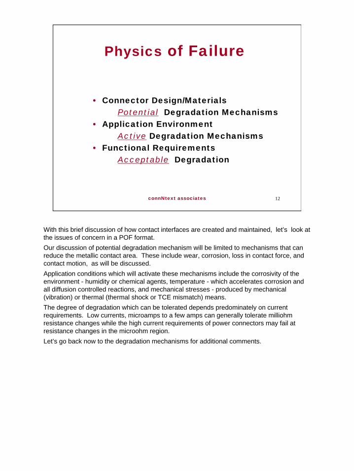
This is a simple version of the basics of Physics of Failure, POF101, but it covers the aspects we need to use for the purposes of today’s presentation:Design and material choices determine a laundry list of the kinds of things which can go wrong, a list of potential degradation mechanisms. The application environment determines which of the potential degradation mechanisms will be activated.And the functional requirements on the connector determine how much degradation can be tolerated, in other words, how much of a change in resistance can be tolerated before the system can no longer operate. Recall my claim that the stability of the contact interface determines a connector’s performance and reliability. Let’s apply POF101 to the contact interface to see how it works, so we can understand what can go wrong and we can then return to these comments in more detail.

7
connNtext associates 7
Contact Interface Morphology
• Roughness• Durability/Friction• Contact Resistance
G33B3609
A (100X)
B (10 X)4
As stated earlier, on the microscale of the contact interface all surfaces are rough. That roughness is schematically illustrated in this slide and it shows that a contact interface between rough surfaces will consist of a number of high spots which happen to come into contact as the surfaces are brought together. These contact areas are referred to as a-spots or asperities and are the defining characteristic of a contact interface as far as its electrical and mechanical performance are concerned. I am sure that the following discussion is common knowledge to this audience, but for completeness I’ll briefly describe how the a-spot morphology affects contact interface durability, or wear, friction and contact resistance.
8
connNtext associates 8
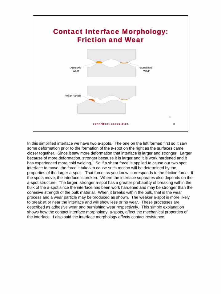
Contact Interface Morphology:Friction and Wear
04
“Adhesive”Wear
Wear Particle
“Burnishing” Wear
In this simplified interface we have two a-spots. The one on the left formed first so it saw some deformation prior to the formation of the a-spot on the right as the surfaces came closer together. Since it saw more deformation that interface is larger and stronger. Larger because of more deformation, stronger because it is larger and it is work hardened and it has experienced more cold welding. So if a shear force is applied to cause our two spot interface to move, the force it takes to cause such motion will be determined by the properties of the larger a-spot. That force, as you know, corresponds to the friction force. If the spots move, the interface is broken. Where the interface separates also depends on the a-spot structure. The larger, stronger a-spot has a greater probability of breaking within the bulk of the a-spot since the interface has been work hardened and may be stronger than the cohesive strength of the bulk material. When it breaks within the bulk, that is the wear process and a wear particle may be produced as shown. The weaker a-spot is more likely to break at or near the interface and will show less or no wear. These processes are described as adhesive wear and burnishing wear respectively. This simple explanation shows how the contact interface morphology, a-spots, affect the mechanical properties of the interface. I also said the interface morphology affects contact resistance.

9
connNtext associates 9
Contact Interface Morphology: Contact Resistance
G01C509
R pc R B BRR C
R PC
R O = R 2 P.C. + 2 R BULK + R C
Before we get to the interface a few comments on the various resistances in a mated connector may be in order. This simple connector cross section shows that the overall resistance Ro consists of two permanent connection resistances, the press-in connection on the right and the crimped connection on the left; two bulk resistances due to the receptacle and plug contacts; and the resistance of the contact interface where the receptacle and plug mate.Permanent connection resistances are of the order of microohms, bulk resistance contributions typically of the order of milliohms and the interface resistance is about a milliohm in most connectors. A milliohm is an acceptable resistance for most applications, excluding power connectors, so why the fuss.The fuss is because the interface resistance is the most likely of these resistance contributions to vary. Bulk resistances are basically constant, permanent connection resistance stability is generally very good. The variable resistance is the separable interface resistance for the reasons I stated earlier. Let’s see why this is so.

10
connNtext associates 10
Contact Interface Morphology: Constriction Resistance
G506439
3.5
3
2.5
2
1.5
1
.5
0 0 50 100 150
Load (gm)
Res
ista
nce
(moh
m)
200 250 300
αR = ρ / a
R = ρ / na + /DC ρ
Constriction Resistance
vsNormal Force
= KR ρ / DC ρ H / F
This slide shows constriction resistance versus contact force for a clean metal surface. In this discussion, clean means free from surface films whether they be corrosion products or contaminants. In other words, we are bringing two metal surfaces together directly and electron transfer occurs freely between the metals. Recalling that on the scale of the contact interface all surfaces are rough we see that at low forces only a few a-spots are created. It can be shown that the resistance of a single a-spot is proportional to rho/a where rho is the resistivity of the metal and a the diameter of the a spot. As the force increases bringing the surfaces closer together additional a-spots will form. Their individual resistances will be in parallel as indicated by the first term in the second equation. The second term is added to account for the distribution of the a-spots. Current is first constricted to flow into the distributional area, of diameter D, and then microconstricted to flow through the individual a-spots. These distributional and a-spot resistances are in series. When the number of a-spots is large, a few tens, their parallel resistance becomes small compared to the distributional contribution and the constriction resistance is dominated by the rho over D term. Electrically it behaves as a single full area contact. But there will always be a constriction resistance, therefore, there will always be a contact resistance. It can be controlled and minimized, but it cannot be eliminated. Under “full area” contact conditions it becomes possible to calculate the constriction resistance, as shown in the third equation on the slide.
11
connNtext associates 11
Constriction Resistance
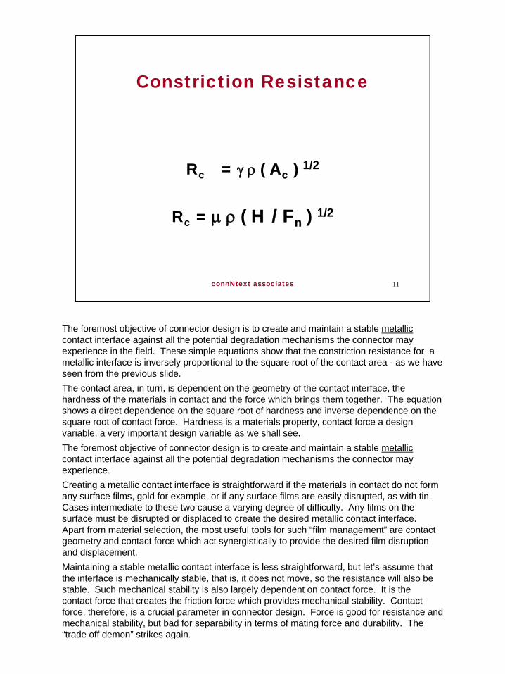
Rc = γ ρ ( Ac ) 1/2
Rc = µ ρ ( H / Fn ) 1/2
The foremost objective of connector design is to create and maintain a stable metallic contact interface against all the potential degradation mechanisms the connector may experience in the field. These simple equations show that the constriction resistance for a metallic interface is inversely proportional to the square root of the contact area - as we have seen from the previous slide. The contact area, in turn, is dependent on the geometry of the contact interface, the hardness of the materials in contact and the force which brings them together. The equation shows a direct dependence on the square root of hardness and inverse dependence on the square root of contact force. Hardness is a materials property, contact force a design variable, a very important design variable as we shall see.The foremost objective of connector design is to create and maintain a stable metalliccontact interface against all the potential degradation mechanisms the connector may experience.Creating a metallic contact interface is straightforward if the materials in contact do not form any surface films, gold for example, or if any surface films are easily disrupted, as with tin. Cases intermediate to these two cause a varying degree of difficulty. Any films on the surface must be disrupted or displaced to create the desired metallic contact interface. Apart from material selection, the most useful tools for such “film management” are contact geometry and contact force which act synergistically to provide the desired film disruption and displacement.Maintaining a stable metallic contact interface is less straightforward, but let’s assume that the interface is mechanically stable, that is, it does not move, so the resistance will also be stable. Such mechanical stability is also largely dependent on contact force. It is the contact force that creates the friction force which provides mechanical stability. Contact force, therefore, is a crucial parameter in connector design. Force is good for resistance and mechanical stability, but bad for separability in terms of mating force and durability. The “trade off demon” strikes again.
12
connNtext associates 12
Physics of Failure
• Connector Design/MaterialsPotential Degradation Mechanisms
• Application EnvironmentActive Degradation Mechanisms
• Functional RequirementsAcceptable Degradation
With this brief discussion of how contact interfaces are created and maintained, let’s look at the issues of concern in a POF format.Our discussion of potential degradation mechanism will be limited to mechanisms that can reduce the metallic contact area. These include wear, corrosion, loss in contact force, and contact motion, as will be discussed. Application conditions which will activate these mechanisms include the corrosivity of the environment - humidity or chemical agents, temperature - which accelerates corrosion and all diffusion controlled reactions, and mechanical stresses - produced by mechanical (vibration) or thermal (thermal shock or TCE mismatch) means.The degree of degradation which can be tolerated depends predominately on current requirements. Low currents, microamps to a few amps can generally tolerate milliohm resistance changes while the high current requirements of power connectors may fail at resistance changes in the microohm region.Let’s go back now to the degradation mechanisms for additional comments.

13
connNtext associates 13
Constriction ResistanceDegradation
• Durability• Corrosion
Static (Surface)Dynamic (Fretting)
• Loss in Contact ForceStress Relaxation
Durability refers to the wear that takes place during mating of the connector and can result in the loss of the contact finish and the finish properties that were designed in to enhance the connector performance. Durability depends on the finish material, the contact geometry and the contact force - materials/design parameters - and the number of mating cycles the connector must support - an application parameter.There are two related corrosion mechanisms of interest. Surface corrosion which occurs in and around the contact interface, and fretting corrosion which is corrosion that is enhanced or stimulated by movement of the contact interface. Both mechanisms can lead to contact failure with the dominant mechanism depending on the material of the contact finish. For example, noble metals are not susceptible to fretting corrosion while the dominant failure mechanism in tin finished connectors is fretting corrosion. Finally, loss in contact force. I have already noted the importance of contact force as a design parameter so it is no surprise that loss in contact force should contribute to degradation. The major effect of loss in contact force is a reduction in mechanical stability that leads to an increased susceptibility to motion of the contact interface. Motion, in turn increases the sensitivity of the interface to corrosion as shown in the next slide.

14
connNtext associates 14
Contact Motion and Corrosion
0 2
C O N T A C T
C O R R O S IO NP R O D U C T
A
B
C
Micromotion
Micromotion
After N CyclesInsulated
New Oxide Film
Initial
Broken Oxide Film
New Oxide Film
0.1 mil
(a)
(b)
(c)
(d)
There are at least two ways contact motion affects corrosion. The first is classic fretting corrosion where contact motion exposes a substrate to corrosion and the wear process causes a build up of wear debris and corrosion products at the contact interface. The study of fretting corrosion is another area in which Mort Antler made significant contributions.The second is when contact motion results in a loss in contact area as the contact interface moves onto corrosion products, or contaminants, around the contact interface. While the slide shows large contact interface motion to clearly illustrate the mechanism, the motion can occur on a microscale with the loss of contact area occurring interior to the contact interface, as in fretting corrosion. The motion can also lead to external corrosion products or contaminants being dragged into the contact interface from an exterior location. In either case a degradation in contact resistance can occur which increases with time and repetitive movement of the contact interface.It is my opinion that movement of the contact interface is a major contributor to contact resistance degradation. And, this mechanism also provides an explanation for the restorative effect of plugging and unplugging of connectors on performance. The large scale motions during mating cause a wiping action which restores the metallic contact interface by displacing any corrosion products and contaminants in or around the contact interface.

15
connNtext associates 15
Physics of Failureand
Connector Reliability
• Connector Degradation ModelingSimulating connector degradation
Connector Design/MaterialsApplication/Activation
• Connector Reliability AssessmentSimulating/Stimulating connector degradationTesting protocols
With durability, corrosion, loss in contact force and contact interface motion in mind, let’s now return to our POF approach and how it can be used to build reliability into a connector.A POF approach leads to systematic modeling of connector degradation. The modeling process identifies the important connector design/materials considerations and their interaction with the driving forces for degradation which exist in the application environment. Insight into materials selection/performance issues, for both the contact finish -noble or non-noble - and the contact spring -stress relaxation and loss of contact force, for example..Modeling also provides insight into reliability assessment in that the process details highlight the roles of factors which stimulate degradation and the dependence of these factors on application conditions. For example, the application temperature affects corrosion rates, stress relaxation rates and thermal expansion contributions to stresses at the contact interface. We will see that the application temperature is a very significant and synergistic contributor to degradation and, thus, to connector reliability. However, because of such synergies the insights of degradation modeling with respect to connector reliability are not always straightforward for reasons discussed in the next slide.
16
connNtext associates 16
Physics of Failure and
Degradation Modeling
• Degradation Mechanism ModelingStraightforward but potentially complex.
• Degradation/Performance RelationshipsIntrinsically complex.
Malucci
∆ R = k r n (∆T)p Cm W s
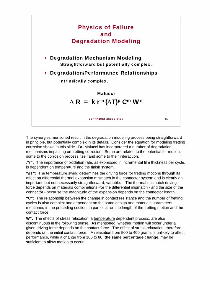
The synergies mentioned result in the degradation modeling process being straightforward in principle, but potentially complex in its details. Consider the equation for modeling fretting corrosion shown in this slide. Dr. Malucci has incorporated a number of degradation mechanisms impacting on fretting corrosion. Some are related to the potential for motion, some to the corrosion process itself and some to their interaction. .“r”: The importance of oxidation rate, as expressed in incremental film thickness per cycle, is dependent on temperature and the finish system.“∆T”: The temperature swing determines the driving force for fretting motions through its effect on differential thermal expansion mismatch in the connector system and is clearly an important, but not necessarily straightforward, variable. The thermal mismatch driving force depends on materials combinations -for the differential mismatch - and the size of the connector - because the magnitude of the expansion depends on the connector length. “C”: The relationship between the change in contact resistance and the number of fretting cycles is also complex and dependent on the same design and materials parameters mentioned in the preceding section, in particular on the length of the fretting motion and the contact force. W”: The effects of stress relaxation, a temperature dependent process, are also discontinuous in the following sense. As mentioned, whether motion will occur under a given driving force depends on the contact force. The effect of stress relaxation, therefore, depends on the initial contact force. A relaxation from 500 to 400 grams is unlikely to affect performance, while a change from 100 to 80, the same percentage change, may be sufficient to allow motion to occur.

17
connNtext associates 17
Physics of Failure and
Degradation Modeling
• Degradation Mechanism ModelingStraightforward but potentially complex.
• Degradation/Performance RelationshipsIntrinsically complex.
Malucci
∆ R = k r n (∆T)p Cm W s
The degradation mechanism modeling leading to this equation is quite sophisticated and reasonable, and, as stated previously, provides insight into a number of materials/design/application considerations and interactions.Making the transition across the “equality sign”, a transition from degradation modeling to a relationship with the change in contact resistance, however, is intrinsically complex due to the variety and complexity of application/design/material interactions. Dr. Malucci has addressed this concern by using field data and mathematical curve fitting to determine the exponents in the equation for a particular connector system and test/field conditions. Sophisticated modeling cannot get us across the equals sign, correspondence with test and/or field data is critical. This is also true of the tests themselves as will be discussed.

18
connNtext associates 18
Physics of Failureand
Testing Protocols
• Simulating the Application EnvironmentProvide the correct “active agents”
• Stimulating the Degradation MechanismsEnhance the “active process(es)”
• “Acceleration Factor” Test Duration (enhancement) v Application Life
Two factors in laboratory simulation approaches to reliability estimation and the role of POF in enhancing their applicability will be discussed.The test environment must accurately and appropriately simulate the effects of the application environment in all relevant aspects. For example, considering corrosion as a degradation mechanism, POF analysis would identify the active species for corrosion of noble metal finishes as HCl, SO2, H2S and SO2. Means for enhancing the active processes also come out of the degradation modeling. The concentration of the active agents would appear in any corrosion rate equation and the role of temperature in corrosion, stress relaxation and, in many cases, contact motion (through its contributions to delta T), would also appear. Such an analysis would yield guidelines into the degree of enhancement, the first step towards an acceleration factor.As discussed with respecrt to Malucci’s equation however, to establish a valid acceleration factor requires that a relationship between time in the test environment and lifetime in the field be defined or developed. The work done at Battelle Laboratories under Bill Abbott is a classic example of an analytical and field based development of an acceleration factor for corrosion related degradation of noble metal finished connector systems. With these comments in mind, lets look at a range of connector testing protocols to satisfy different requirements.

19
connNtext associates 19
Design Verification Testing
A test, or series of tests, intended to verify a particular performance characteristic.
ExampleDurability testing:
Simulation is direct,Acceleration is time compression
DVT is done by a connector manufacturer during the product development process. The design goals for a connector system include some contact resistance value and target durability and mating force as a minimum. DVT would simply measure the contact resistance and mating force to validate design objectives. The connector system would also be durability cycled, mated and unmated, to some target value. Such cycling, of course, directly simulates the application and a straightforward acceleration factor can be obtained by appropriately varying the cycling rate of the connector. Once DVT is completed the product is ready for the next round of testing protocols.
20
connNtext associates 20
Specification/Qualification Testing
A prescribed sequence of tests and requirements
to validate a “minimum”
performance capability.
Product/Industry/Customer
S/QT requires better definition of protocols. The test sequence and requirements may be defined by the connector manufacturer in a Product Specification or in a Standards document by a industry group such as EIA, TIA, IPC etc. in the US or by the ISO or IEC in international standards. A Corporation may also issue its own specification such as Bellcore/Telcordia 1217. In most cases such specifications call for test groups to be subjected to dedicated operational stresses and “minimum” performance requirements which are not necessarily related to field performance.A generic “qualification” test protocol is shown in the next slide.

21
connNtext associates 21
Specification/Qualification Testing
GENERIC TEST PLAN
ELECTRICALRESISTANCE
SHOCK
VIBRATION
ELECTRICALRESISTANCE
GROUP1
MATING/UNMATINGFORCE
ELECTRICALRESISTANCE
DURABILITY
MATING/UNMATINGFORCE
ELECTRICALRESISTANCE
THERMALSHOCK
ELECTRICALRESISTANCE(OPTIONAL)
HUMIDITY
ELECTRICALRESISTANCE
GROUP2
I R
DWV
THERMALSHOCK
HUMIDITY
I R
DWV
GROUP3
ELECTRICALRESISTANCE
PRECONDITIONING
ELECTRICALRESISTANCE
HARSH ENV.
ELECTRICALRESISTANCE
GROUP4
MATING/UNMATINGFORCE
ELECTRICALRESISTANCE
TEMP. LIFE
ELECTRICALRESISTANCE
MATING/UNMATINGFORCE
GROUP5
SUPPLEMENTALTESTS
GROUP6
SAMPLE PREPARATION
Group 1 applies mechanical stresses directed towards assessing the mechanical stability of the contact interface. Acceptable contact resistance is the requirement, usually a change in resistance or Delta R value.Group 2 tests mating force before and after durability cycling to assess wear effects on mating force followed by thermal shock - testing mechanical stability - and humidity - testing corrosion - exposures with contact resistance the requirement. The corrosion exposure comes after conditioning the contact interface by durability cycling. Group 3 tests the housing using thermal shock - mechanical - and humidity - polymer degradation - exposures and Insulation Resistance and Dielectric Withstanding Voltage as requirements.Group 4 tests corrosion resistance with preconditioning - which may include durability cycling and heat soak - prior to exposure to “harsh environment” - dependent on contact finish - and contact resistance as the requirement.Group 5 tests for stress relaxation effects using temperature life - heat soak - as a conditioning exposure and mating/unmating force - as a mechanical requirement - and contact resistance as an electrical requirement.Group 6 is an optional application specific group. An example would be for automotive connectors which may be subjected to more demanding vibration/shock and temperature stresses than electronic connectors. Similarly, power connectors may be required to meet additional requirements such as MilliVoltDrop or Temperature Rise.In most cases, as mentioned, the requirements are generic and not necessarily related to performance requirements.
22
connNtext associates 22
Performance Verification Testing
A set of test sequences and requirements directed towards
a specific application.
Test:Sequence/Severities/Durations
Requirements:Function
PVT differs from S/QT in that the intent is to validate the performance of a connector in a specific application rather than the generic intent of S/QT. While a similar test protocol may be used, the testing environments may be more demanding in terms of severities and duration. For example an S/QT corrosion test group may call for 10 days in a Class II environment while a PVT test for a connector to be used in a process control application may call for 20 days in a Class IV environment. The requirements may also be more demanding. For example a common delta R for contact resistance after exposure is 10 milliohms. Depending on the current and signal integrity requirements a tighter delta R requirement may be applied.Test protocols and requirements get even more scrutiny if the intent of the test program is to assess the connector reliability.

23
connNtext associates 23
Reliability Assessment Testing
A set of test sequences,
including acceleration factors, and requirements,
including failure criteria, for a specific application.
The red highlighted items are the major amendments in going from PVT to RAT. The requirements, delta R, in our case, are more specific. A resistance value which causes failure must be known. This value is, of course, not the maximum allowed in the test. Rather, it is the target value for the maximum resistance which the tail of the resistance distribution is allowed to approach. This is where the “probability” part of the definition of reliability comes into play. The mathematical analysis for such decisions/definitions is beyond the scope of this presentation, but its importance should not be overlooked. Reliability assessment always includes statistical treatment of the test data.The test exposures must not only be valid, that is reproduce the known field failure responses, but a relationship between the test exposure duration and field lifetime must be known. This is necessary because the definition of reliability includes a reference to the design lifetime of the product.Let’s look at acceleration factors in a bit more detail.

24
connNtext associates 24
Reliability Assessment Testing
Corrosion: T/H or F M G Simulation: EnvironmentAcceleration: ?
Stress Relaxation: Heat aging.Simulation: DirectAcceleration: Stimulation/direct,
but performance?
Corrosion acceleration factors have already been discussed to a limited degree. Simulation of the application environment in the test exposure environment is reasonably straightforward after a lot of field work. The acceleration factors also come from the same field work by correlating test exposed samples with similar samples exposed in the field. The difficulty comes from the fact that it is not just the materials which determine the corrosion performance of a connector. It is well known that the housing design shields the contact interface from the environment on the gross scale. It is also well known that the a-spots within the contact interface are “shielded” by the interface distribution. So a materials “acceleration factor” is available, but the next step to a connector performance “acceleration factor” is a bit more problematic.Similar considerations apply to stress relaxation and its effect on contact normal force. Heat aging at elevated temperatures directly accelerates stress relaxation and the acceleration factor, from an Arhennius viewpoint, can be calculated and supported by empirical data onmany materials. But the next step, from stress relaxation induced loss in contact force, to the effect on contact resistance again is problematic. Recall that the effect of contact force on resistance includes both creating and maintaining the contact interface. Once the interface is created under a given contact force, reducing that force may not change the contact area, thus the contact resistance, apart from a small elastic recovery. In other words, the unloading force v resistance curve does not retrace the loading curve. Loss in contact force, however, may reduce mechanical stability, which, in turn, may lead to contact motion and the degradation in resistance previously described. Whether motion occurs occurs at the reduced force depends on the original contact force. Low force systems will, of course, be more susceptible to this form of degradation.

25
connNtext associates 25
Reliability Assessment Testing
Serial Test Program
End Of LifeEOL
Assessment Criteria
These comments are not intended to disparage attempts to assess connector reliability by either modeling or testing procedures. They are only intended to highlight issues that must be taken into consideration when interpreting the results of both modeling and testing approaches to assessment of connector performance/reliability. To support my commitment to these remarks, let me describe a testing approach to reliability assessment. It consists of a serial test program with one group of samples being subjected to all test exposures. This is more representative of field conditions than multiple groups with each group being exposed to a single or limited set of exposures as discussed in S/QT approaches. The test exposures are intended to represent End Of Life (EOL) conditions as determined by previous POF modeling or test results.As noted earlier the assessment criteria should be based on failure values.

26
connNtext associates 26
Reliability Assessment Testing
08
StartExaminationof Product
Dry CircuitResistance
TemperatureRise & MVDvs. Current
DurabilityHumidity
(Tin Systems)
Industrial MixedFlowing Gases(Gold & Silver
Systems)
TemperatureLife Vibration
Dry CircuitResistance
TemperatureRise & MVDvs. Current
End
This is one example of such a program. Let’s go through the steps. 1. Examine the test samples to ensure that they meet the product specification with respect to manufacturing specifications and requirements. We are, after all, assessing the reliability of a part made to print. 2. Dry circuit measurement of contact resistance provides the baseline. Dry circuit refers to an open circuit measurement voltage of 20/50 millivolts. This low voltage is intended to ensure that any surface films are not electrically disrupted. 3. If the connector is intended for power/high current applications T-rise and MilliVoltDrop measurements are recommended.4. Durability cycling conditions the contact interface. EndOfLife may be the rated durability of the connector, say 200 cycles, or some “typical” value, say 100 cycles. This is an engineering decision. The purpose of durability conditioning is, of course, to increase the susceptibility of the contact interface to corrosion, the next step.5. The appropriate corrosion exposure depends on the finish system. Humidity or humidity cycling is commonly used for tin finished systems. Unfortunately there is no generally agreed acceleration factor for such exposures which prohibits a reliability assessment in principle, but does not prevent comparative assessments against field data. IMFG is used for noble metal and silver finished systems. Acceleration factors for noble systems are available and, controversially, accepted.6. Temperature life follows. This, too is a conditioning step intended to reduce the contact force to an EOL value that puts the contact system into a state of increased susceptibility to contact motion under mechanical or thermal stresses. Acceleration factors for temperature life, that is, stress relaxation, are available.

27
connNtext associates 27
Reliability Assessment Testing
08
StartExaminationof Product
Dry CircuitResistance
TemperatureRise & MVDvs. Current
DurabilityHumidity
(Tin Systems)
Industrial MixedFlowing Gases(Gold & Silver
Systems)
TemperatureLife Vibration
Dry CircuitResistance
TemperatureRise & MVDvs. Current
End
7. Vibration is a commonly used mechanical stress in connector testing. There are numerous issues in vibration testing that are beyond the scope of this presentation. A POF approach to vibration testing, however, does provide a way to address many of the these issues and is being actively pursued, for example in the Computer Aided Life Cycle Engineering program at the University of Maryland. The intent of vibration exposure is straightforward. It is intended to assess the mechanical stability of the contact interface against mechanically induced contact motion and the associated degradation processes previously discussed.8. Dry circuit resistance follows to assess the amount of degradation which has taken place during the conditioning and exposures.9. Again, for power/high current connectors T-rise and MVD are recommended. These measurements should follow the dry circuit measurement since the voltages applied in T-rise and MVD may be higher than dry circuit levels.Other, or additional, conditioning and exposures may be appropriate and the order of conditioning/exposure is also subject to discussion, but the proposed program represents a good generic approach. One modification which has been discussed is to do multiple loops of the sequence at durations less than EOL to more appropriately represent the continuous exposures in the field and to promote synergistic interactions. For example, the conditioning steps of durability and heat age could be done to 20 percent of EOL with the cycle repeated five times to attain EOL. This, of course, increases the complexity and cost of the test program but may be warranted in some cases.

28
connNtext associates 28
Conclusion
A Physics of Failureapproach to
connector reliability provides a consistent framework
for ensuring the reliability of connector designs
and the relevance of reliability assessment test methods/protocols.
This slide sums things up. The importance of POF is the system, the consistent framework of analysis, modeling, empirical validation and repeat. This approach increases the probability that the connector design and test protocols which result from its application have addressed the important issues and accounted for them in a manner appropriate to the intended application of the connector. Its not new, its just good engineering and science applied systematically.One of the charges to the Antler Lecturer is to “promote new research activities in the electrical contact area”. I suggest that further investigation into the issues I have raised with respect to simulation and stimulation of degradation mechanisms and the challenges of defining acceleration factors are fertile ground for further work. And, in my opinion, POF methods are the appropriate tools to use in approaching these issues.