a parallel algorithm for locating short circuits on printed circuit boards
TRANSCRIPT

I 7
746 IEEE TRANSACTIONS ON INSTRUMENTATION AND MEASUREMENT, VOL. 42, NO. 3, JUNE 1993
A Parallel Algorithm for Locating Short Circuits on Printed Circuit Boards
Yiu-Wing Leung
Abstract-To locate all the short circuits on a printed circuit hoard, Fang [l] proposed an efficient algorithm that finds the shorted paths one by one and groups these shorted paths into equivalence classes. By properly grouping the signal paths and testing one group of signal paths against another group at a time, Fang showed that this algorithm has the worst-case com- plexity O(x log, N ) , where N and x are the numbers of signal paths and shorted paths respectively. Based on Fang’s algo- rithm, we propose in this paper a parallel algorithm for locating all the short circuits on a printed circuit board. By using M current sources of different frequencies and M band- pass filters of different passbands, this algorithm tests M groups of signal paths against M respective groups simultaneously. We show that this algorithm has the worst-case complexity O(x log, N ) and a much smaller average complexity than Fang’s algo- rithm.
I. INTRODUCTION the production of electronic products, the products I” undergo a number of testing phases to ensure that high-
quality products are manufactured [ 2 ] . One of the testing phases is to test for short circuits among the signal paths on the printed circuit boards. This test is carried out be- fore electronic components are mounted onto a bare printed circuit board. Otherwise, the short circuits may damage the electronic components, and the cost of de- tecting and repairing the resulting faults will become much higher.
The simplest testing method, called N-square test [l], tests every pair of signal paths on the printed circuit board. If there are N signal paths, this method requires (N2 - N ) / 2 tests. To reduce the required number of tests, Garey, Johnson, and Ho [3] proposed a graph coloring approach to detect whether there is a short circuit on the printed circuit board. To further reduce the required num- ber of tests, the manufacturers introduced an instrument called short detector that can test for short circuits be- tween two groups of signal paths in one test [ l], [4]. The short detector drives current into one group of signal paths and detects whether there is current flowing in the other group. With this instrument available, linear test [ 11 tests each signal path against all the other paths in each test. Hence, only N tests are needed to identify all the shorted paths. However, where these paths are shorted to is not determined. Skilling [4] patented a testing method that
Manuscript received May 27, 1992. The author is with the Department of Information Engineering, The
IEEE Log Number 9208055. Chinese University of Hong Kong, Shatin, Hong Kong.
integrates the linear test and the N-square test. First, lin- ear test is invoked to identify all the shorted paths. Sec- ond, square test is applied on these shorted paths to de- termine where they are shorted to. If there are x shorted paths, Skilling’s test requires N + (x2 - x ) / 2 tests.
Fang [l] introduced an efficient algorithm for locating all the short circuits on a printed circuit board. He pointed out that if path i is shorted to path j and path j is shorted to path k, then path i is also shorted to path k. Then it can be shown that d3 = { (i, j ) I path i is shorted to path j ] is an equivalence relation. The key idea of Fang’s algorithm is to find the shorted paths one by one and group these shorted paths into equivalence classes. By properly grouping the signal paths and testing one group of signal paths against another group at a time, Fang [ l ] showed that this algorithm requires only O ( x log2 N) tests.
In Fang’s algorithm, only one group pair of signal paths is tested at a time. Otherwise, the current flowing in one group pair may flow to the other pair through the short circuits. Based on Fang’s algorithm, we propose in this paper a parallel algorithm for locating all the short circuits on printed circuit boards. The main idea of this parallel algorithm is to use M current sources of frequencies f, , f2, * , fM (fi # f2 # * - - # fM), and each current source drives current to one group of signal paths. By using M proper bandpass filters, we can detect whether there is current of a particular frequency flowing in each of the M groups of signal paths. Then we can determine whether there are short circuits between the first group pair, be- tween the second group pair, - * - , and between the Mth group pair. Hence, M groups of signal paths can be tested against M respective groups simultaneously.
In Section 11, we propose a multifrequency short detec- tor that drives currents of frequencies fi , f2, - * , fM into M groups of signal paths and detects the current flowing in each of the M groups of signal paths. In Section 111, we propose a parallel algorithm for locating all the short cir- cuits on printed circuit boards and in Section IV, we ana- lyze and compare both the worst-case complexity and the average complexity of the parallel algorithm and Fang’s algorithm.
11. MULTIFREQUENCY SHORT DETECTOR A multifrequency short detector is an enhanced design
of the short detector described in Section I. It drives si- nusoidal currents I , , Z2, * - - , ZM of respective frequencies
0018-9456/93$03.00 0 1993 IEEE

I I
I, from Central controller
LEUNG: A PARALLEL ALGORITHM FOR LOCATING SHORT CIRCUITS
To central Detector module M wntroller
control
Current Driver
Controller control Signal Central M
Fig. 1 . Multifrequency short detector.
fi , f2, * , fM into M groups of signal paths. By detecting whether there is current of a particular frequency flowing in each of the M groups of signal paths, it can determine whether there are shorted paths between the M group pairs.
Fig. 1 shows a block diagram of a multifrequency short detector. It consists of a central controller, a current driver, and a current detector. The central controller ex- ecutes the parallel algorithm described in Section 111, de- termines how the sign1 paths are grouped in the next test and sends this grouping information to the current driver and the current detector via the control lines. Then it re- ceives the detection results from the current detector via the detection lines and determines whether there are shorted paths between the group pairs of signal paths.
Fig. 2 shows a block diagram of a current driver. It consists of M driver modules and N adders. Driver mod- ule i drives current Zi of frequencyJ to a given group of signal paths. This is achieved by connecting the current source to N relays. Each relay is a three-terminal element that connects its input to its output only when its control input is high. The relay controller receives grouping in- formation from the central controller and sends relay en- able signals to the proper relays such that the current source is actually connected to only a predetermined group of signal paths. As explained in Section 111, a signal path may be included in one or more groups in one test. Adders are therefore needed so that currents of different frequen- cies can flow in the same signal path simultaneously.
Fig. 3 shows a block diagram of a current detector. It consists of M detector modules. Detector module i detects whether there is current of frequency 5 flowing in a given group of signal paths. Within detector module i , the N signal paths are connected to N relays. A relay controller receives grouping information from the central controller and sends relay enable signals to the proper relays such that only a predetermined group of signal paths is actually connected to the adder at a time. The bandpass filter in detector module i only passes signals of frequency J and blocks signals of frequency& for a l l j # i . The outputs of all the bandpass filters are connected to the central con-
from Central- mntrollar
from EntraL
741
lriver module 1
-73% To path 1
To path 2
mntroller
controller Driver module M
Fig. 2. Current driver.
Detector module 1
I from oath 1
I I r-- I
filter 1
I I I ’ I
Tocentral controller
Detector module 2 controller
I * I I I * I I I I 1
troller, which can then determine whether there are short circuits between the M group pairs of signal paths.
111. THE PARALLEL ALGORITHM Let P = (1, 2 , - - * , N} be a set of signal path iden-
tities and suppose the number of shorted paths x is not known a priori. The parallel algorithm consists of three procedures, called short testing procedure, short local- ization procedure, and short diagnosis procedure. These procedures are described and explained in the following subsections.
A. Short Testing Procedure The short testing procedure determines whether there is
any short circuit among the N signal paths. The set of signal paths P is bisected into level 1 disjoint sets G ! and

I I
748 IEEE TRANSACTIONS ON INSTRUMENTATION AND MEASUREMENT, VOL. 42, NO. 3 , JUNE 1993
G: (i.e, GI and G: have the same number of elements if N is even, and G ; contains one or more element than G: if N is odd). Then Gt is bisected into level 2 disjoint sets G: and G:, and G: is bisected into level 2 disjoint sets G: and G:. In general, level i disjoint sets are bisected into level i + 1 disjoint sets until only singleton sets (i.e., set containing only one element) remain (see Fig. 4). There are a total of [log,? N 1 bisection levels with 2' disjoint sets in bisection level i.
For bisection level 1, the signal paths in G f form one group, those in G: from another group, and we test G ; against G:. For bisection level 2, the signal paths in G: U G: form one group, those in Gi U G: form another group, and we test G: U G: against G: U G:. In general, for bisection level i, we test U:: Gik- against U:: 1 Gik. Since there are M current sources, M group pairs (i.e., M bisection levels) can be tested simultaneously. If at least one short circuit is detected, the short testing pro- cedure is stopped and outputs 1 which is the smallest bi- section level of the group pair having at least one short circuit between them. Otherwise, it outputs 1 = 0 to in- dicate that no short circuit is found.
sM] be a short indicator array where si = 1 if the ith group pair has a shorted pair and si = 0 otherwise. The short testing procedure is given below:
Let s = [sl, s2 * *
Short Testing Procedure [Input: P; Output: 11
1 . i + O ; l + O ; 2. PARALLEL ( j=1 ,2 ; * * , M )
4. 3. H p j U k = 2 0 + f - l ) I GizL I ; H p J c U:'"{-" Gip;
IF no short circuit is found between H p ' and HpJ THEN ~j 6 0 ELSE ~j + 1 ;
5 . END PARALLEL; 6. IF s1 v s2 v 7. THEN i 6 i + Mand GO TO line 2 8. ELSE 9. IF s1 V s2 V - V sM = 1 THEN 1 + i +
* v sM = 0 and i + M < [log2 N 1
min { j l s j = l}; 10. STOP; 1 1 . END ELSE.
B. Short Localization Procedure
If the short testing procedure fin$s?t least one short circuit between U:': Gik- and uk= Gik and outputs 1, then the short circuit is between the group pair G: and G: or between G: and G:, or, - - - , or between GLr- and Gkr. (However, the short circuit is not between, say G: and G;, or otherwise there is a short circuit between U k = G&: and U:':: G:; (see Fig. 4), and the short testing procedure outputs 1 - 1 instead of 1.) The short localization procedure finds m such that G:, - and Gi, have at least one shorted pair.
We partition { G { , G:, - - , G:I - I } into M sets U 1 , U,, * * - , G:/} into VI, V2, - , VM. The unions of all the elements in Vi and Vi
21 - 2
, UM and partition {Gi , G:,
--bisection level 1
--bisection level 2
\ 2 --bisection level 3
L A /B . /\
* - - G;e-, G;e --bisection level e /\ /\
G: G; G: G:
Fig. 4. Bisection of the set of signal paths.
are denoted U; and vi, respectively. For example, if U1 = G[, , G ; } , then U , = G: U G:. The signal paths in U; form one group, and those in U ; form another group. We test ui against ui f o r i = 1 , 2, * * , M in parallel. Suppose a short circuit is found between uj and vj . If Uj and V, -are the singleton sets { G:, - I } and { G;,} , respectively, then the short localization procedure is stopped and outputs m. Otherwise, Uj and VJ are partitioned into respective M sets, and the above test is repeated.
* - , $x} is partitioned into M sets, let SI(*) denote the set containing the first
and S,(*) denote the set containing the second r x / M 1
etc. The short localization procedure is given below:
If a given set \k = {$,, $2,
[ x / M 1 elements (i.e., SI(*) = $2, - - * , $ r x / M 1 1)
elements (i.e., SA*) = {$rx/M1 - $2rx/M1 11,
1. 2. 3. 4.
5 . 6. 7.
C.
Short Localization Procedure [Input: 1 Output: m]
L +- U$:: {Gkk-I}; R +- U:':: {Gik}; PARALLEL ( i = l , 2, * - - , M )
U; + Si(L); Vi +- S;(R); IF no short circuit is found between U; and U,
THEN si + 0 ELSE S; + 1; END PARALLEL; find j such that sj = 1; IF UJ and V, are singleton sets THEN find m such that L = {Gkm-l} and R =
ELSE L + U J ; R + b; GO TO line 2. {GL,}; STOP
Short Diagnosis Procedure The short localization procedure finds that Gkm- and
G:, have at least one shorted pair. The short diagnosis procedure finds a and b such that a E G:, - I , b E G:, and a is shorted to b.
, AM, test these M groups against G:, in parallel and find j such that Aj and G:, have at least one shorted pair. Second, we divide G:, into M groups B 1 , B2, * , BM, test these M groups against Aj in parallel and find k such that Bk and Aj have at least one shorted pair. If Aj or Bk are not sin- gleton sets, we repeat the above tests with G:, - replaced
We first divide Gk,,,- I into M groups A I , A2,
I
149 LEUNG: A PARALLEL ALGORITHM FOR LOCATING SHORT CIRCUITS
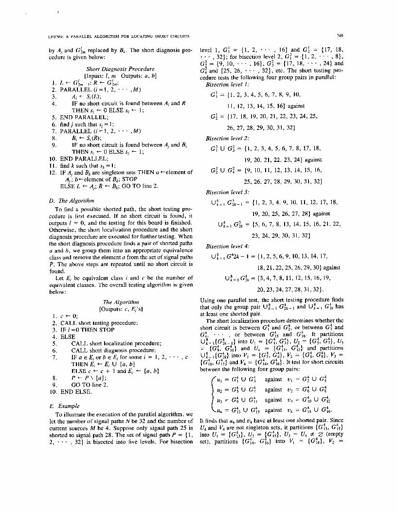
by Ai and G:, replaced by Bk. The short diagnosis pro- cedure is given below:
1. 2. 3. 4.
5 . 6. 7. 8. 9.
10. 11. 12.
D.
Short Diagnosis Procedure [Inputs: 1, m Outputs: a , b]
L + Gim- I ; R + G;,; PARALLEL( i= l ,2 , * - - , M )
Ai + S;(L); IF no short circuit is found between Ai and R THEN S; + 0 ELSE S; + 1;
END PARALLEL; find j such that si = 1 ; PARALLEL ( i = l , 2,
Bi + Si (R); IF no short circuit is found between Aj and Bi
* * ,M)
THEN S; + 0 ELSE S; + 1; END PARALLEL; find k such that sk = 1; IF Aj and Bk are singleton sets THEN a +element of
ELSE L + Aj; R + Bk; GO TO line 2. Aj; b te lement of Bk; STOP
The Algorithm To find a possible shorted path, the short testing pro-
cedure is first executed. If no short circuit is found, it outputs 1 = 0, and the testing for this board is finished. Otherwise, the short localization procedure and the short diagnosis procedure are executed for further testing. When the short diagnosis procedure finds a pair of shorted paths a and b, we group them into an appropriate equivalence class and remove the element a from the set of signal paths P. The above steps are repeated until no short circuit is found.
Let E; be equivalent class i and c be the number of equivalent classes. The overall testing algorithm is given below:
The Algorithm [Outputs: C, E;'s]
1. c + o ; 2. CALL short testing procedure; 3. IF 1 = O THEN STOP 4. ELSE 5 . CALL short localization procedure; 6. CALL short diagnosis procedure;
THEN Ei + E; U {a, b} ELSE c + c + 1 and E, + (a, b}
8. P + P \ {a}; 9. GO TO line 2.
7. 1 F a E E ; o r b E E ; f o r s o m e i = 1,2, , c
10. END ELSE.
E. Example To illustrate the execution of the parallel algorithm, we
let the number of signal paths N be 32 and the number of current sources M be 4. Suppose only signal path 25 is shorted to signal path 28. The set of signal path P = { 1, 2, - - - , 32) is bisected into five levels. For bisection
level 1, GI = (1, 2, - , 16) and G: = (17, 18, . . . , 32); for bisection level 2, G: = (1, 2, , 8}, G: = (9, 10, * - - , 16}, G i = (17, 18, , 24) and G: and (25, 26, - - * , 32}, etc. The short testing pro- cedure tests the following four group pairs in parallel:
*
*
Bisection level 1:
G', = (1, 2, 3, 4, 5, 6, 7, 8, 9, 10,
11, 12, 13, 14, 15, 16) against
G l = (17, 18, 19, 20, 21, 22, 23, 24, 25,
26, 27, 28, 29, 30, 31, 32)
Bisection level 2:
G:UG:=(1,2,3,4,5,6,7,8,17,18,
19, 20, 21, 22, 23, 24) against
G: U G i = (9, 10, 11, 12, 13, 14, 15, 16,
25, 26, 27, 28, 29, 30, 31, 32)
Bisection level 3: 4 3 Uk=l G2k-1 = (1, 2, 3, 4, 9, 10, 11, 12, 17, 18,
19, 20, 25, 26, 27, 28) against
U:=, Gik = ( 5 , 6, 7, 8, 13, 14, 15, 16, 21, 22,
23, 24, 29, 30, 31, 32)
Bisection level 4:
U,"=, G42k- 1 = {1,2,5,6,9, 10, 13, 14, 17,
18,21,22,25,26,29,30} against
U,"= , G& = (3,4,7,8, 11, 12, 15, 16, 19,
20,23,24,27,28,31,32).
Using one parallel test, the short testing procedure finds that only the group pair U,"= Gik - and U," = I 6% has at least one shorted pair.
The short localization procedure determines whether the short circuit is between G; and G;, or between G i and G:, - , or between G:5 and Gj6. It partitions U,"=I(G:k-I} into UI = {G;, Gi}, U, = {Gz, G;}, U, = {G& G;,} and U, = (G:3, Gj5} and partitions U,"=,(G&} into VI = {Gi , G:}, V2 = (G:, Gi}, V3 = {G:o, G:,} and V4 = (G:4, G;6} . It test for short circuits between the following four group pairs:
against ul = G; U G:
against u2 = G t U G i
against v3 = G:o U G$ r u4 = GG U G;5 against u4 = G;4 U G;6.
It finds that u4 and v4 have at least one shorted pair. Since U, and V4 are not singleton sets, it partitions { Gj3, G;5} into U1 = (G:3}, U, = {G;5}, U3 = U, # 0 (empty set), partitions (G;4, G&} into VI = (G?4}, V2 =
uI = G; U G i
u2 = G: U G j
u3 = GG U G;,

I
750 IEEE TRANSACTIONS ON INSTRUMENTATION AND MEASUREMENT, VOL. 42, NO. 3, JUNE 1993
(&), v3 = V4 = 0 and tests the following four group pairs in parallel:
{U, = G:3 against v1 = G:4
u2 = G;5 against v2 = Gj6 1 u1 = 0 against vl = 0 u1 = 0 against vl = 0.
Then it finds that G;3 = (25, 26) and G;4 = (27, 28) have at least one shorted pair. The short localization pro- cedure therefore requires two tests.
The short diagnosis procedure finds a shorted pair be- tween Gi3 = (25, 26) and G;4 = (27, 28). It partitions Gt3 into A I = (25}, A2 = (26), A3 = A4 = 0 and tests these four groups against Gj4 in parallel. It finds that A I and G;4 have a shorted pair. Then it partitions G;'4 into B1 = (27}, B2 = (28), B3 = B4 = 0 and tests these four groups against A l in parallel. It finds that A I = (25) and B2 = (28) have a shorted pair. Since both A I and B2 are singleton sets, the test is completed. The short diag- nosis procedure requires two tests.
Using our proposed parallel algorithm and using four current sources, only five tests are required. However, if Fang's algorithm is used, it can be shown that 13 tests are required.
IV. COMPLEXITY ANALYSIS The complexity is measured in terms of the required
number of tests.
A. Worst-case Complexity The parallel algorithm finds the short circuits one by
one. Consider the detection of the first shorted pair. The short testing procedure can test M bisection levels in one test. If there is no short circuit between the group pairs in the first (1 - 1) bisection levels but there is at least one short circuit between the group pair in the lth bisection level, the short testing procedure requires x1 = r l / M 1 tests. The short localization procedure determines whether the short circuit is between G: and G:, or between G: and Gk, or, * , or between G:,- I and G:,. In each test, we can test M groups of signal paths against M respective groups simultaneously. Therefore, the required number of tests x2 can be found as follows:
MX2-1 < 21-1 5 MX2
The short diagnosis procedure finds a shorted pair be- tween G:, - l and G;,. Since both G:, - l and G:, contain 2 rlogzN1 -' signal paths, the required number of tests x3 can be found as follows:
~ ( x 3 / 2 ) - 1 < 2 rlOg2Nl - 1 .= ~ X 3 / 2 -
Hence, the required number of tests to locate the first shorted pair can be bounded as follows:
x , + x* + x3
5 ( ; + 1 ) + ( = + 1 ) log2 M '
which has the order O(log,,N). The first shorted path is then removed from P and Gf's. When the second shorted path is to be found, the total number of paths to be con- sidered becomes N - 1 . As a result, the required number of tests to locate the second shorted path is not larger than that to locate the first shorted path. Therefore, if there are x shorted paths, the worst-case complexity of the parallel algorithm is 0 (x logw N) .
B. Average Complexity Using computer simulation, we obtain the average
complexity by averaging the measured complexities in 1 000 simulation experiments. In these experiments, a short circuit connects two randomly chosen signal paths. Fig. 5 compares the average complexity of Fang's algo- rithm and the parallel algorithm with M = 4. As the num- ber of signal paths N increases, the average complexity of the parallel algorithm increases at a slower rate than that of Fang's algorithm. When x = 5 and N = 26, the average complexity of the parallel algorithm is 36.65% of that of Fang's algorithm. However, when N is increased to 213, the average complexity of the parallel algorithm is only 29.78% of that of Fang's algorithm.
Fig. 6 shows that the average complexity of the parallel algorithm decreases as M increases. Therefore, we can reduce the required number of tests by simply using a larger number of current sources at a higher cost. How- ever, it should be noted that doubling M does not neces- sarily reduce the average complexity by half. For exam- ple, if N = 213, the respective average complexities for M = 1, 2, 4, and 8 are 250, 132.4, 73.95, and 54.36. Therefore, in this case, parallel algorithm is most cost effective when M is not large (say 4 5 M 5 8).
V. CONCLUSIONS We proposed in this paper a parallel algorithm for lo-
cating all the short circuits on a printed circuit board. The main idea of this algorithm is to use M current sources of frequenciesfi,&, * - - , # f w ) such that each current source drives current to one group of signal paths. By using M proper bandpass filters, we can
- ,fM(fi # & f ,

LEUNG: A PARALLEL ALGORITHM FOR LOCATING SHORT CIRCUITS 75 1
Average complexity
3oo I 250
200
1 50
100
50
I I I I I I I
Average complexity
I 250
200
150
1 00
50
I I 1 1 I I I
N ~~
N Fig. 5 . Average complexity versus N(M = 4) . Fig. 6. Average complexity of the parallel algorithm versus N(K = 10).
detect whether there is current of a particular frequency flowing in each Of the kf groups of Signal paths. Then we can determine whether there are short circuits between the group pairs. H ~ ~ ~ ~ , M groups of signal paths can be tested against kf respective groups simultaneously. We Shwed that this parallel algorithm has the worst case complexity ’(’ logV N, and a much than Fang’s algorithm.
REFERENCES [ I ] s. c. Fang, “Detecting electrical shorts on printed circuit boards,”
[2] J. Turino, H. F. Binnendyk, “Comprehensive test strategies help cut
[3] M. R. Garey, D. S . Johnson, H. C. Ho, “An application of graph
Inr. J . Prod. Research, vol. 28, no. 6, pp. 1031-1037, 1990.
costs of manufacturing,” Electronics, pp. 80-83, Dec. 1981.
coloring to printed circuit testing,” IEEE Trans. Circuits and Sysrems, vol. 23, pp. 591-599, 1976.
[4] J . K. Skilling, “Method of electrical shorts testing and the like,” US Patent #4342959, Aug. 1982.
average