a novel view on lubricant flow undergoing cavitation in sintered journal bearings
DESCRIPTION
elastohydrodynamics principlesTRANSCRIPT

A novel view on lubricant flow undergoing cavitation in sintered journal bearings
Bernhard Scheichl1a,b,∗, Ioana Adina Neacsu1a, Alfred Kluwickb
aAC²T research GmbH, Viktor-Kaplan-Straße 2D, A-2700 Wiener Neustadt, Lower AustriabInstitute of Fluid Mechanics and Heat Transfer, Vienna University of Technology, Tower BA/E322, Getreidemarkt 9, A-1060 Vienna, Austria
Abstract
A new rational formulation of the cavitation phenomenon occurring in porous journal bearings in the regime of fullyhydrodynamic lubrication is presented. The suitably extended form of the Reynolds equation is coupled with thesemi-phenomenological Darcy’s law so as to yield a proper description of the combined flow through the lubricationgap and the porous (sintered) seat, respectively. It is found that the initially unknown boundaries of cavitation giveinevitably rise to gradual steepenings of the pressure gradients and the saturation of the lubricant at recondensationthat finally form up to localised discontinuities. Hence, itis focussed on both theoretical foundations and an elabo-rate numerical investigation of the resultant lubricationproblem. In order to determine the limits of applicability ofthis approach, specific investigations aim at evaluating the extreme cases of relatively low and high bearing loads,i.e.ε→ 0 andε→ 1_ whereε is the eccentricity ratio, and very long/short as well as highly porous/(almost) massivebearings. Here the effort is seen to be reduced by considering appropriate distinguished limits. The results includevalues of the friction coefficient obtained for various configurations and, most interestingly, point to a threshold valueof ε above which the loss of numerical solutions indicates the loss of steady-state operation of the bearing. A firstvalidation by in-house experiments proves satisfactory.
Keywords: Cavitation, Darcy flow, Hydrodynamic lubrication, Porous journal bearings
1. Introduction
When the friction forces between parts in relative motion have to be minimal, a thin layer of either oil, greaseor solid particles is commonly introduced between the parts, as to avoid the undesired surface contact. In journal(i.e. slide) bearings this separation is accomplished by the action of hydrodynamic lubrication, where a fluid film thatcarries the load imposed on the bearing is formed as a result of the rotation of the eccentrically displaced journal. Inconventional or massive bearings, this mechanism is maintained steadily through a localised supply of the lubricant,i.e. external reservoir of lubricant. In contrast, here we are interested in mass-preserving journal bearings, also referredto as self-lubricated bearings, which operate in a similar manner as classical journal bearings. The fundamentaldifference is the porous (sintered) seat: its impregnation withlubricant is necessary only once (at the beginning of thelifecycle of the bearing).
The literature on this subject is enormous and constantly growing, thereby expressing the thriving interest anddemand for self-lubricated bearings by engineers. Manufacturing and application of porous journal bearings mo-tivating much research in this direction, pondered in [1]. Unfortunately, an overview covering the most importantdevelopments in the reliable computational prediction of the behaviour of such systems and the underlying theoreticalapproaches is not existing, at least to the authors’ knowledge. Therefore, in the following we just cite the publica-tions considered most relevant and/or pioneering in terms of originality and classical but do not claim that this list isexhaustive in nature. The ultimate goal of this study is gaining a deepened understanding of the flow behaviour inself-lubricated bearings and hence a satisfactorily accurate prediction of their steady-state operation.
1see talk at the 39th Leeds–Lyon Symposium on Tribology (Great Challenges in Tribology), Leeds Trinity University College, 4–7 Sept. 2012∗Corresponding author, email:[email protected], phone:+43-(0)2622-81600-158, fax:+43-(0)2622-81600-99
Preprint submitted to Tribology International February 12, 2015
We therefore focus at a most simple self-consistent description of the physical mechanisms at play; shortcomingsarising from non-rational modelling of the physics involved (though at a higher level of complexity) are avoided. Tothis end, some new/established theoretical aspects are in turn highlighted/revisited in greater breadth and depth asusually in the corresponding tribological literature. In this spirit, the present paper and fully numerical studies onthe subject complement. Regarding the latter, the very recent one by Balasoiu et al. [2] serves as a useful example:they adopt the full governing equations for multiphase flow,supplemented with advanced semi-phenomenologicalclosures. In contrast, the numerical analysis performed here and forming the central part of our study (Section 4)• rests upon a careful, critical re-examination of the underlying physics on the different scales involved (Sec-
tion 1),• a thorough formulation of the lubrication problem involving the minimum number of non-dimensional groups
(Section 2), which enables• (as a side issue) a rigorous though preliminary analytical study dealing with several theoretical aspects of the
problem not addressed previously (Section 3) and including• (as an exciting novelty) the inevitable event of spontaneous recondensation, i.e. of saturation jumps, in steady-
state operation of self-lubricated bearings (due to their periodic geometry),• brings in a new efficient numerical strategy that copes with cavitation of an incompressible lubricant involving
that phenomenon and tackles directly the steady-state operation (Section 4.1),• eventually allows for a systematic parameter study and prediction of the bearing performance (Section 4.2),• attended by an experimental validation (Section 4.3).
1.1. Self-lubrication of porous bearings
The basic principle behind the functioning of these type of bearings is that a porous network acts as a reservoir ofthe fluid so as to achieving a cohesive lubricant film In the loaded part of the bearing the lubricant is pushed into theporous channels of the seat, while the flow through the unloaded part contributes in refilling this lubrication gap [3].Therefore, the main factor which influences the capability of storing and releasing lubricant is porosity, defined as theratio between the void fraction and the total volume of the porous bearing. Common values for porosity lie between20% and 35%, depending on the type of application (e.g. requiring a minimum of mechanical strength of the seat).
The porous network forming the seat consists of highly contorted and interconnected microscopic channels. Thedescription of the creeping flow percolating through this entangled network on a macroscopic length scale, representedby the local distance ˜r from the centre of the seat, most commonly is based upon Darcy’s law. It can be derivedformally from the Stokes-flow assumption on the microscopicscale of a fluid (lubricant) with uniform dynamicviscosity η and density by means of scale separation involving a proper homogenisation (averaging) process: werefer to the seminal papers [4–6] (and references therein).The thereby resulting quantities comprise the local porosityor void fractionφ of the sinter, the local flow velocityv, and the difference ˜p between the local pressure and that inthe (gaseous) environment of the bearing, ˜pa, taken as uniform:
φ(x) :=1
VS
∫
SΣ(x′) dVS , [v, p]( x) :=
1
φ(x)VS
∫
S[v′, p′]( x′, x)Σ(x′) dVS , x′ =
xσ
for σ ≪ VS(σ)1/3
r≪ 1 . (1)
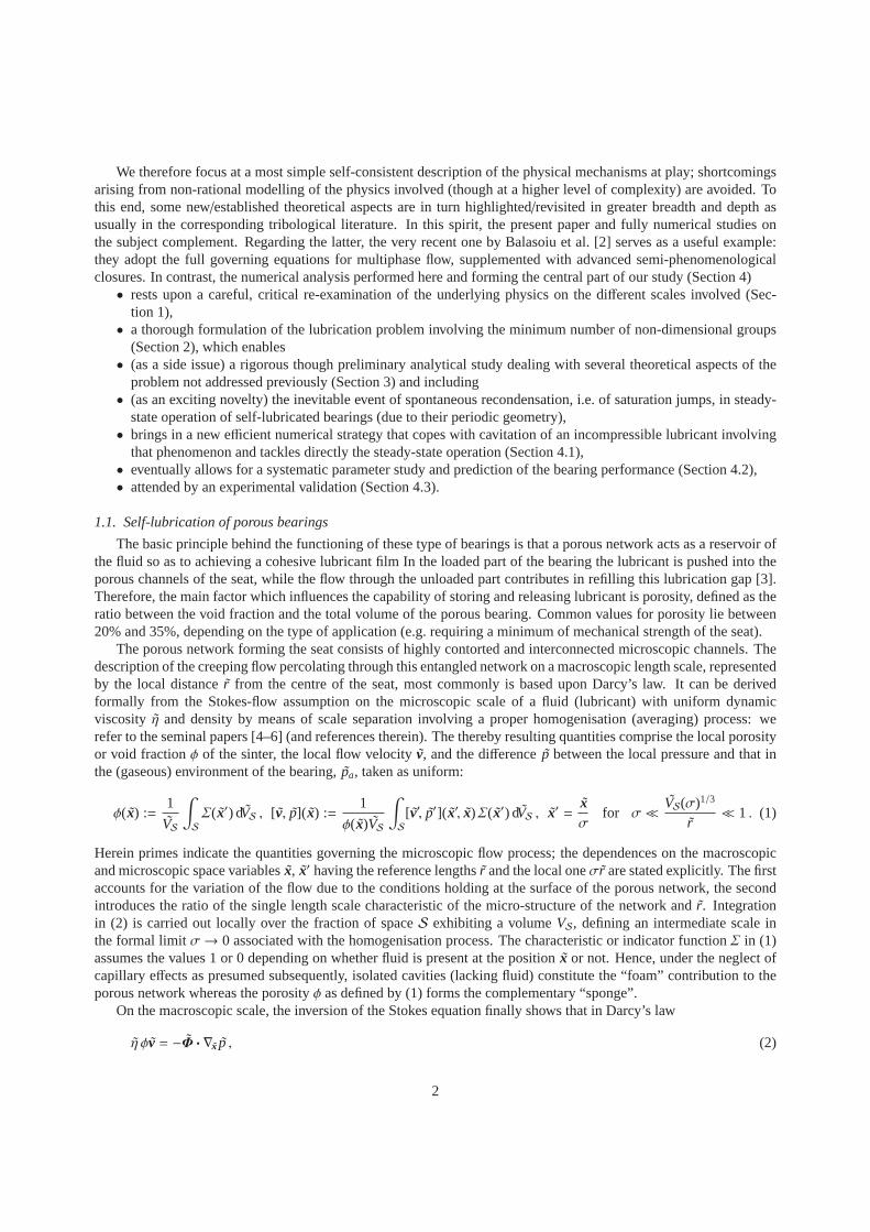
Herein primes indicate the quantities governing the microscopic flow process; the dependences on the macroscopicand microscopic space variablesx, x′ having the reference lengths ˜r and the local oneσr are stated explicitly. The firstaccounts for the variation of the flow due to the conditions holding at the surface of the porous network, the secondintroduces the ratio of the single length scale characteristic of the micro-structure of the network and ˜r. Integrationin (2) is carried out locally over the fraction of spaceS exhibiting a volumeVS, defining an intermediate scale inthe formal limitσ→ 0 associated with the homogenisation process. The characteristic or indicator functionΣ in (1)assumes the values 1 or 0 depending on whether fluid is presentat the positionx or not. Hence, under the neglect ofcapillary effects as presumed subsequently, isolated cavities (lackingfluid) constitute the “foam” contribution to theporous network whereas the porosityφ as defined by (1) forms the complementary “sponge”.
On the macroscopic scale, the inversion of the Stokes equation finally shows that in Darcy’s law
η φv = −Φ · ∇x p , (2)
2

now correctly including the porosity, the symmetric permeability tensorΦ arises from the homogenisation process.Under the assumptions made above, this geometrical quantity is a functional ofφ solely. However, due to the evidentlypractical (numerical) inaccessibility of theΦ-φ-relationship it is the permeability rather than (2) one should termphenomenological. The scalar porosity is apparently much more susceptible to measurement than the permeability,i.e. the components ofΦ, but this is of limited benefit in view of a reliable modellingof Φ. Nevertheless, a numberof semi-empirical expressions and theories were proposed,among which the one advanced by Kozeny [7], heresee also the classical textbook by Scheidegger [8], remainsthe most widely appreciated. His approach is based onthe rough assumption that the porous medium is equivalent toa set of quite slender circular channels exhibitingvarying area cross-sections embedded in a rigid matrix. Theequation he derived expresses the dependence of thepermeability on the specific overall surface area of the porous medium. However, many subsequent experimentalstudies, cf. [8], pp. 137–144, show severe deviations from the theoretical results. For this reason, formulating theindividual components ofΦ and assigning the missing values to the arising parameters is still merely empiricalat present; their reliable measurements are challenging. In many important cases,φ and, in turn,Φ can be takenas homogeneous, i.e. constant (isopermeable material), and/or Darcy’s law (2) as a locally orthotropic constitutiverelationship. ThenΦ is represented only by its three diagonal components. In thecommonly assumed case of alocally perfectly isotropic tensorΦ it is even purely spherical and determined by the single scalar Φ = tr(Φ)/3. In themost basic case of homogeneous isotropy this scalar is againa constant.
We emphasise that the extensions of (2) by Brinkman [9] (accounting for a smooth transition of the homogenisedtowards the cohesive flow adjacent to a porous surface) and interms of the well-known Darcy–Brinkman–Forchheimerlaw (accounting for inertial effects) are definitely phenomenological if not inconsistent at all with the basic assumptionof creeping flow. This motivates us to use Darcy’s classical law in the form stated by (2). Applying the continuityequation∇x · (φv) = 0 ensuing from the homogenisation process to (2) finally yields the equation
∇x ·(
Φ · ∇x p)
= 0 (3)
governing the macroscopic or Darcy pressure. In case of isotropy, (3) reduces to Laplace’s equation.
1.2. Cavitation in lubrication
The hydrodynamic pressure generated in the fluid film betweena rotating shaft and a bearing was first consid-ered rigorously by Osborne Reynolds in 1886. For what follows, the classical prerequisites of lubrication theory areadopted: a Newtonian lubricant in laminar flow where inertial forces are negligibly small compared to the viscousones and a relatively thin lubrication gap. Consequently, from neglecting the inertia terms in the leading thin-layerapproximation of the Navier–Stokes equations the Couette–Poiseuille velocity profile ensues; substituting this approx-imation for v in the continuity equation and integrating it across the gapheight yields the familiar Reynolds equation,governing the Reynolds or lubrication pressure [10]. Most of the the subsequent lubrication models have been basedon this equation, viewed as a milestone, ever since. However, this description is strictly valid only for an assumedfully coherent fluid film, as in the case of quite low values of the eccentricity ratio
(
/ 0.5)
. In reality, the lubricantoften exhibits an almost discontinuous phase change from the initial liquid phase, when the hydrodynamic pressuredrops significantly in the divergent part of the lubricationgap, even below the ambient pressure, usually and as hereindicating atmospheric conditions, and for relatively moderate loads, i.e. eccentricities. This discontinuity associatedwith the sudden pressure decrease is referred to as cavitation. The possibility to incorporate the drop of the pressurebelow the ambient pressure has been the goal of much research, but due to the complexity of the underlying physics,this challenge has been mastered only insufficiently so far.
The critical quantity in lubrication is the local difference pressure ˜p, all the more as the formation of local cavitationaffects the overall behaviour of the bearing under varying conditions in a subtle manner. Here two main mechanismshave been identified in the literature, see the early study byTaylor [11] and the review by Dowson & Taylor [12]:cavitation is provoked either by
(i) the penetration of quite large amounts of gas (air) from the surroundings, thus favouring film rupture from thesurface of the seat and accompanying the formation of a bubble or cavity so that ˜p varies only insignificantlyabout the zero-pressure level, or
(ii) an inner partial vaporisation of the lubricant in fullysubmerged (flooded) bearings into a mixture of liquid(containing dissolved gases as air) and vapour (and released gases), where ˜p may even take on correspondingly
3
q
l
e
z
l~
r~
~
~
~
~
r1
~
r2
2p - y
~
W
~
L
(a) (b)
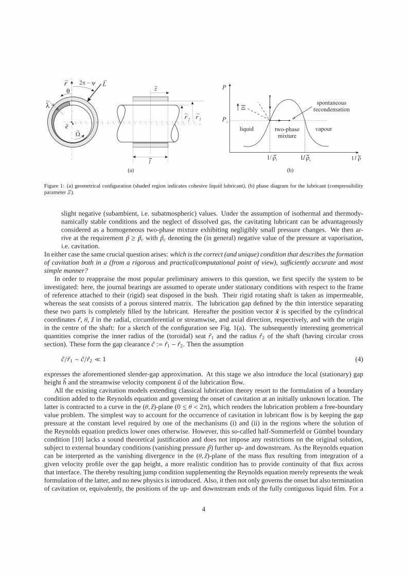
Figure 1: (a) geometrical configuration (shaded region indicates cohesive liquid lubricant), (b) phase diagram for the lubricant (compressibilityparameterΞ).
slight negative (subambient, i.e. subatmospheric) values. Under the assumption of isothermal and thermody-namically stable conditions and the neglect of dissolved gas, the cavitating lubricant can be advantageouslyconsidered as a homogeneous two-phase mixture exhibiting negligibly small pressure changes. We then ar-rive at the requirement ˜p ≥ pc with pc denoting the (in general) negative value of the pressure at vaporisation,i.e. cavitation.
In either case the same crucial question arises:which is the correct (and unique) condition that describes the formationof cavitation both in a (from a rigorousandpractical/computational point of view), sufficiently accurateandmostsimple manner?
In order to reappraise the most popular preliminary answersto this question, we first specify the system to beinvestigated: here, the journal bearings are assumed to operate under stationary conditions with respect to the frameof reference attached to their (rigid) seat disposed in the bush. Their rigid rotating shaft is taken as impermeable,whereas the seat consists of a porous sintered matrix. The lubrication gap defined by the thin interstice separatingthese two parts is completely filled by the lubricant. Hereafter the position vectorx is specified by the cylindricalcoordinates ˜r, θ, z in the radial, circumferential or streamwise, and axial direction, respectively, and with the originin the centre of the shaft: for a sketch of the configuration see Fig. 1(a). The subsequently interesting geometricalquantities comprise the inner radius of the (toroidal) seatr1 and the radius ˜r2 of the shaft (having circular crosssection). These form the gap clearance ˜c := r1 − r2. Then the assumption
c/r1 ∼ c/r2 ≪ 1 (4)
expresses the aforementioned slender-gap approximation.At this stage we also introduce the local (stationary) gapheighth and the streamwise velocity component ˜u of the lubrication flow.
All the existing cavitation models extending classical lubrication theory resort to the formulation of a boundarycondition added to the Reynolds equation and governing the onset of cavitation at an initially unknown location. Thelatter is contracted to a curve in the (θ, z)-plane (0≤ θ < 2π), which renders the lubrication problem a free-boundaryvalue problem. The simplest way to account for the occurrence of cavitation in lubricant flow is by keeping the gappressure at the constant level required by one of the mechanisms (i) and (ii) in the regions where the solution ofthe Reynolds equation predicts lower ones otherwise. However, this so-called half-Sommerfeld or Gümbel boundarycondition [10] lacks a sound theoretical justification and does not impose any restrictions on the original solution,subject to external boundary conditions (vanishing pressure p) further up- and downstream. As the Reynolds equationcan be interpreted as the vanishing divergence in the (θ, z)-plane of the mass flux resulting from integration of agiven velocity profile over the gap height, a more realistic condition has to provide continuity of that flux acrossthat interface. The thereby resulting jump condition supplementing the Reynolds equation merely represents the weakformulation of the latter, and no new physics is introduced.Also, it then not only governs the onset but also terminationof cavitation or, equivalently, the positions of the up- anddownstream ends of the fully contiguous liquid film. For a
4

smooth distribution of the gap heighth, the most general form of such a revised condition then reads
1r∂p∂θ− r∂p∂z
dθdz=
6Uη
h2
[
1− 2ϕ − (1− ϕ)S]
, S =ρm
ρl. (5)
Here ˜r is identified with either ˜r1 or r2 in view of the thin-gap assumption (4), ˜η is taken as the local dynamic viscosityof the liquid lubricant,U denotes the (not necessarily stationary) shaft speed, and ˜ρl , ρm are the local densities of theliquid and the aforementioned mixture, respectively, withS := ρm/ρl being the saturation of the latter (0< S ≤ 1).Furthermore,ϕ represents the fraction of the gap adjacent to the shaft thatcarries a liquid film of uniform velocityUover the otherwise cavitating lubricant (0≤ ϕ < 1). The gradient of ˜p is taken to be zero in the cavitation region. Inthe fully liquid phase, however, it approaches a negative/positive limit as expressed by the left-hand side of (5) indirection normal to the interface, having a local slope dθ/dz in the (θ, z)-plane, at the onset/termination of cavitation.In the region of cavitation or incomplete lubrication,S supersedes ˜p as the dependent variable governing the gap flow,whereas the value ofϕ has to be determined by an analysis taking into account capillary effects.
As early as in 1932, Swift [13] and Stieber [14] were the first who addressed the onset of cavitation in the spiritof (i). They neglected the continuation of a coherent liquidand, simultaneously, assumed a continuous initiation ofgas entrainment as they setϕ = 0 andS = 1. Then (5) reduces to the celebrated Reynolds boundary condition ofNeumann-type governing the cavitation interface [10]. Later on, [11, 12], flow separation, triggered by an adversepressure gradient acting in streamwise direction, was considered as the essential physical mechanism accompanyingfilm rupture: its position and that of a vanishing shear rate∂u/∂r at one of the solid facing surfaces forming thelubrication gap coincide. This criterion was investigatedin the above studies for an infinitely long bearing entailingaplanar flow with no ˜z-dependence. When observed in the frame of reference fixed to one surface, here cavitation takesplace in the divergent part of the lubrication gap slightly upstream of the location of its minimum height, and a liquidfilm moves under and/or above the cavity. The Couette–Poiseuille form of the flow then predicts film rupture where
dp/dθ = 2r ηU/h2 . (6)
By combining this criterion, involving the local structureof the flow, with (5), arising from a contraction process, onecould fix the position of cavitation in advance. However, consistency of this procedure has not been demonstratedso far. In contrast, Floberg [15] demonstrated how sub-cavity pressures imply film rupture further downstream. Hewas the first who considered this phenomenon as a rather abrupt transition from the coherent liquid film towards aruptured one that moves as separated from the seat at rest by acavity, filled entirely with air having negligible densitywith respect to the lubricant. This picture exactly leads tothe condition (5), but with the restrictionS = 0. In addition,Floberg also neglected the thickness of the ruptured liquidlayer by settingϕ = 0, so he assumed that cavitation affectsthe transverse section of the gap as a whole. This view is supported well by his own experiments and those conductedby Braun [16], who concluded it (out of all three proposed cavitation conditions outlined above) to reflect best theexperimental findings. Additionally, his recent review [17] on the cavitation problem in bearings covers a vast amountof the cavitation models available in the literature, and represents a sound overview on the developments in this field.
It is stressed that the prediction of cavitation based on (5)disregards the frequently observed manifestation ofcavitation in the form of spanwise fingering or individual streamers due to capillary effects ([15, 18], cf. [19]) andby inclusion of the resultant pressure jump in (5) (here Savage’s work [20, 21] is among the forerunners, also ofthe associated stability analysis for both uniform and wavyspanwise cavitation fronts). For vaporous cavitationconsidered here, also the associated Gibbs–Thomson effect has not attracted attention in literature to the authorsknowledge.
By critically evaluating the different ideas of modelling cavitation above, we abandon (6) aspreference is given tothe criterion (5), which has a clear physical meaning as it accounts for film rupture, see issue (i), and/or in combinationwith the inception of vaporisation, see issue (ii), and film reformation and/or recondensation self-consistently withinthe framework of lubrication theory. In the pure cases (i) and (ii) it has to be supplemented with the self-evidentrequirements ˜p = 0 or p = pc (< 0), respectively. Interestingly, this criterion has apparently not attracted attentionwhen the predominance of mechanism (ii) is presumed: here the inception of vaporisation requires the continuityof S, yielding S = 1, but spontaneous recondensation has to be regarded as the rule rather than the exception. Herethe value ofS jumps from one below 1 to 1 in downstream direction, accompanied by a jump in the pressure gradientfrom zero to that given by (5). Forϕ = 0 at both ends of cavitation (neglect of a remanent liquid layer), (5) is commonlyreferred to as Jakobsson–Floberg–Olsson (JFO) boundary condition: see [15, 22] and the references therein.
5
Most important, the pressure gradient vanishes at vaporisation but, in general, not at recovery. In summary, self-sustained lubrication subject to vaporisation cavitationin the circular gap is associated with two crucial properties:
(I) The Reynolds boundary condition definitely applies to film vaporisation but not to film reformation, i.e. recon-densation;
(II) the distributions of pressure and saturation are smooth throughout except for an open curve in the (θ, z)-plane,associated with spontaneous recondensation as characterised by the gradual steepening of both the local in-crease of saturation up to the value 1 and the pressure gradient to non-zero values, which finally culminates indiscontinuities.
2. Problem formulation
In this section we present the premises of the novel cavitation model that we employ in our study. We note that theflow in the journal bearing exhibits two forms of appearance,where the interaction between the two associated regionspreserves the continuity of mass. In the current configuration, cavitation develops as a stable two-phase regime andexpands in both axial and circumferential direction. Our main concern is with the determination of the gap pressure,including the formation of cavitation, under various load regimes.
2.1. Adopted cavitation model — requirements on lubricant
The lubricant is generally chosen according to various factors, including operation environment, lifetime, and theload-carrying capacity. However, the most influential criterion remains the frictional behaviour. Consequently, a largeamount of research efforts is dedicated to developing novel lubricants with outstanding tribological properties. Pre-liminary tests have shown that ionic liquids exhibit an interesting low wear rate when used as lubricants. Additionally,their properties can be chemically altered and modelled as to their adaption to specific application necessities [23]. It isknown that in journal bearings the vapour pressure of the lubricant plays an important role in the development of cav-itation; hence the pure occurrence of mechanism (ii) addressed in Section 1.2 is favoured. In this respect, ionic liquidsshow interesting attributes: relatively low vapour pressures (which also means a correspondingly reduced tendencyto evaporate over time). Apart from this, they exhibit good thermal stability and a satisfactorily weak dependence ofthe viscosity on temperature. These promising features motivates industry to choose them as prospective lubricantsand us to adopt typical values of viscosity and vapour pressure of those liquids as input parameters for the numericalinvestigation. The sensitiveness of the operating range ofthe bearing to the variation of the vapour pressure is touchedon quantitatively in Section 2.2.
It is reasonable to assume that the bearing is encapsulated in a solid casing, which implies that there is no lubricantleakage from the sinter to the exterior and air cannot enter the lubrication gap. Hence, we assume insulation of thetoroidal cylinder comprising the seat and the gap at its facing sides and outer shell. In the absence of entrainment byexternal gases and under the assumption of an already degassed lubricant that undergoes a pressure drop down to itsvapour pressure, the fluid will vaporise into a two-phase mixture composed of oil and vapour at varying concentrations.This event coins the notion cavitation in the spirit of (ii).Furthermore, it is reasonable to stipulate that the solid partsof the bearing take on the same temperature during operationand its relative increase in the lubricant film by viscousdissipation is negligibly small. The arrow attached to the solid curve in the phase diagram sketched in Fig. 1(b)indicates the resultant isothermal change of state of the lubricant passing the onset of vaporisation,
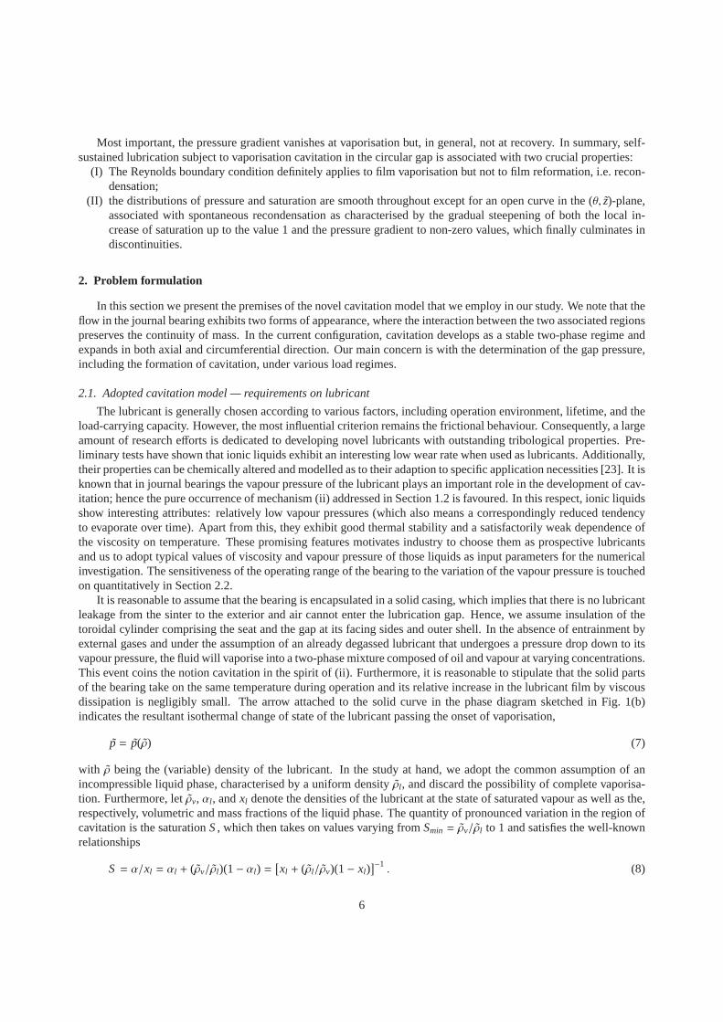
p = p(ρ) (7)
with ρ being the (variable) density of the lubricant. In the study at hand, we adopt the common assumption of anincompressible liquid phase, characterised by a uniform density ρl , and discard the possibility of complete vaporisa-tion. Furthermore, let ˜ρv, αl , andxl denote the densities of the lubricant at the state of saturated vapour as well as the,respectively, volumetric and mass fractions of the liquid phase. The quantity of pronounced variation in the region ofcavitation is the saturationS, which then takes on values varying fromSmin = ρv/ρl to 1 and satisfies the well-knownrelationships
S = α/xl = αl + (ρv/ρl)(1− αl) =[
xl + (ρl/ρv)(1− xl)]−1. (8)
6

Herein the second and the third expression forS reflect the mass-specific and volumetric compositions, respectively,of a fluid particle in the two-phase regime.
Cavitation by vaporisation is governed by the evolution ofS in the two-phase region modelled as a homogenisedmixture of both phases, according to (8). Albeit quite basic, this self-consistent extension of classical lubricationtheory is seen to capture all the essential features of interest on a length scale comparable to the typical dimension (inr- and/or z-direction) of the lubrication gap.
2.2. Governing equations
Together with one of the radii ˜r1, r2 and the gap clearance ˜c introduced in Section 1.2, the shaft eccentricity ˜e, thebearing lengthl, and the radial thickness of the seatλ define the geometry of the bearing. The resultant parametersare the eccentricity ratioε := e/c forming a key quantity as well as the aspect ratiosΓ := (2r2/l )2 andΛ := λ/r1. Theshaft rotates with a constant angular speedΩ (= U/r2) about its axis in direction of the circumferential coordinateθ,and the bearing is considered to operate under stationary conditions. For these kinematic conditions we again referto Fig. 1(a). Since we assume the configuration as isothermaland a not too large pressure increase, it is reasonableto take the viscosity ˜η as uniform. The behaviour of each the two flow regions identified in the system is capturedby a separate equation governing the respective pressure, which are non-dimensional in the usual manner with thereference value
pref := 6 Ωη(r2/c)2 . (9)
The first region is the thin gap between the shaft and bearing,filled entirely with the lubricant (submerged bearing).The displacement of the shaft from its original position dueto rotation leads to the convergent/divergent gap ofheight h or H when made non-dimensional with ˜c. We neglect any tilt of the axes of the shaft and the seat and ofnoticeable roughness of its inner surface (due to its usual finishing and run-in) In the spirit of the central slender-gapapproximation (4),H is then expressed by the well-known leading-order relationship
H(θ) = 1+ ε cosθ , (10)
which under the assumptions made even holds in case of high eccentricities, i.e. forε→ 1−. With z= z/(l/2)and PR(θ, z) and PC being the distribution of the Reynolds pressure and the cavitation pressure, respectively, theReynolds equation, suitably modified in order to cope with both cavitation and the ingestion of lubricant from theporous seat, is then written as
∂
∂θ
(
H3S∂PR
∂θ
)
+ Γ∂
∂z
(
H3S∂PR
∂z
)
=∂(HS)∂θ
− vD,r . (11)
It is supplemented with the three complementary conditions
PR ≥ PC ; S = S(P) (≥ 1) as PR > PC ; S > 0 . (12)
Here the first is of Karush–Kuhn–Tucker-type and bounds the pressure by the cavitation pressure, and the secondmasters the application (11) to a compressible lubricant bythe inversion of (7) in terms of an empirical, (on thermo-dynamic grounds) monotonically increasing functionS(P). Hence, one obtains the limit of perfectly incompressibleflow of uniform density by characterising the fully liquid phase through the
“incomopressible” specification of (12) : P ≥ PC and S ≡ 1 ; 0< S < 1 and PR ≡ PC . (13)
The flow behaviour in the two-phase regime is solely governedby the right-hand side of (11), which accounts for thevariable saturation:Smin ≤ S(θ, z) < 1 in the region whereP ≡ PC. The representation of the flow in the lubricationgap by (11) subject to (12) or, specifically, (13) is more general than and, from the viewpoint of the numerical strategypursued in the following, preferable to the original Elrod–Adams formulation [22, 24]. Elrod’s original techniquewas then adapted successfully in the classical study by Meurisse & Giudicelli [25] to porous journal bearings, aswell as taken up modified subsequently, e.g. in [26]: there a unit step function acting on the left-hand side of (11)and, for a strictly incompressible liquid phase, also onS in terms of a slack variable, provides the “switch” between
7
the single- and the two-phase regime. However, this modification still leavesPR unspecified in the latter rather thanit imposes its bounding from below byPC as the conditions (12) do. In any case, that transition, hereaccountedfor by (12) and even more (13), together with the initially unknown position of the liquid-/two-phase interface inthe (θ, z)-plane (0≤ θ < 2π, 0 ≤ z≤ 1), introduces a nonlinearity in the lubrication problem which proves delicate todeal with due to the sudden vanishing of the left-hand side of(11) in the sought limit of incompressible flow: see [27–29] (and the references therein). By handing over dominanceof the elliptic operator to the advective one governingthe wedge term on the right-hand side, having the characteristic linesz= const, this entails a rather weak couplingbetween the flow regions separated by the phase boundary.
The rightmost (source) term in (11) represents the radial inward mass flux or, complying with the assumptionS ≡ 1of uniform density of the lubricant inside the sinter, velocity component at the inner surface of the porous seat. Thedirection of mass exchange between the latter and the lubricant film by supply/leakage by percolation is given by itspositive/negative sign. The appropriate boundary conditions for (11) are given by periodicity inθ, symmetry withrespect toz= 0, and the prescription of the ambient pressure at the edge (z= 1) of the lubrication gap:
[
PR, ∂PR/∂θ]
θ=0 = [PR, ∂PR/∂θ]θ=2π , ∂PR/∂z∣
∣
∣
z=0= 0 , PR
∣
∣
∣
z=1= 0 . (14)
We note that a non-zero value ofPR atz= 1 due to the pressure jump caused by surface tension was addressed in [25],but a rational refinement of this boundary condition that accounts for a rigorous description of the toroidal liquid rings,sealing the gap and partly the seat by wetting as forming at their faces and driven by capillary and centrifugal forces,has not been carried out so far.
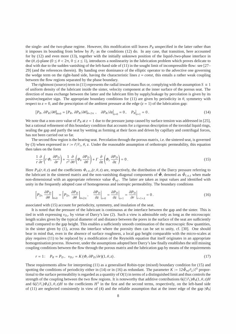
The second flow region is the bearing seat. Percolation through the porous matrix, i.e. the sintered seat, is governedby (3) when expressed inr := r/r1, θ, z. Under the reasonable assumption of orthotropic permeability, this equationthen takes on the form
1r∂
∂r
(
r Φr∂PD
∂r
)
+1r2
∂
∂θ
(
Φθ∂PD
∂θ
)
+ Γ∂
∂z
(
Φz∂PD
∂z
)
= 0 . (15)
HerePD(r, θ, z) and the coefficientsΦr, θ, z(r, θ, z) are, respectively, the distribution of the Darcy pressurereferring tothe lubricant in the sintered matrix and the non-vanishing diagonal components ofΦ, denoted asΦr , θ, z when madenon-dimensional with an appropriate reference valueΦref . The latter are taken as input values and identified withunity in the frequently adopted case of homogeneous and isotropic permeability. The boundary conditions
[
PD,∂PD
∂θ
]
θ=0=
[
PD,∂PD
∂θ
]
θ=2π,∂PD
∂z
∣
∣
∣
∣
∣
z=0=∂PD
∂z
∣
∣
∣
∣
∣
z=1=∂PD
∂r
∣
∣
∣
∣
∣
r=1+Λ= 0 . (16)
associated with (15) account for periodicity, symmetry, and insulation of the seat.It is noted that the pressure of the lubricant is continuous at the interface between the gap and the sinter. This is
tied in with expressingvD,r by virtue of Darcy’s law (2). Such a view is admissible only aslong as the microscopiclength scales given by the typical diameter of and distance between the pores in the surface of the seat are sufficientlysmall compared to the gap height. This enables a sufficiently smooth continuation of the macroscopic flow quantities,in the sinter given by (1), across the interface where the porosity then can be set to unity, cf. [30]. One shouldbear in mind that, even in the absence of surface roughness, alocal gap height comparable with the micro-scales atplay requires (11) to be replaced by a modification of the Reynolds equation that itself originates in an appropriatehomogenisation process. However, under the assumptions adopted here Darcy’s law finally establishes the still missingcoupling conditions between the flow through the porous matrix and the lubrication gap by means of the requirements
r = 1: PR = PD , vD,r = K (Φr ∂PD/∂r)(1, θ, z) . (17)
These requirements allow for interpreting (11) as a generalised Robin-type (mixed) boundary condition for (15) andspotting the conditions of periodicity either in (14) or in (16) as redundant. The parameterK := 12Φref r2/c3 propor-tional to the surface permeability is regarded as a quantityof O(1) in terms of a distinguished limit and thus controls thestrength of the coupling between the two flow regions. It is noteworthy that additive contributions 6( ˜c/r1)Φθ(1, θ, z)Hand 6( ˜c/r1)Φz(1, θ, z)H to the coefficientsH3 in the first and the second terms, respectively, on the left-hand sideof (11) are neglected consistently in view of (4) and the reliable assumption that at the inner edge of the gap|Φθ |
8
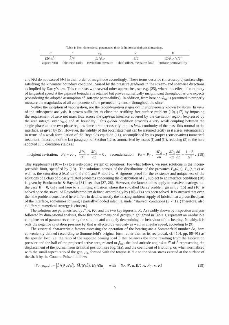
Table 1: Non-dimensional parameters, their definitions and physical meanings.
Γ Λ PC ε K
(2r2/l)2 λ/r1 pc/pref e/c 12Φref r2/c3
aspect ratio thickness ratio cavitation pressure shaft offset, measures load surface permeability
and|Φz| do not exceed|Φr | in their order of magnitude accordingly. These terms describe (microscopic) surface slips,satisfying the kinematic boundary condition, caused by thepressure gradients in the stream- and spanwise directionsas implied by Darcy’s law. This contrasts with several otherapproaches, see e.g. [25], where this effect of continuityof tangential speed at the gap/seat boundary is retained but proves numerically insignificant throughout as one expects(considering the adopted assumption of isotropic permeability). In addition, from here onΦref is presumed to properlymeasure the magnitudes of all components of the permeability tensor throughout the sinter.
Neither the inception of vaporisation, nor the recondensation stages occur at previously known locations. In viewof the subsequent analysis, it proves sufficient to close the resulting free-surface problem (10)–(17) by imposingthe requirement of zero net mass flux across the gap/seat interface covered by the cavitation region (expressedbythe area integral overvD,r ) and its boundary. Thisglobal condition provides a very weak coupling between thesingle-phase and the two-phase regions since itnot necessarily implieslocal continuity of the mass flux normal to theinterface, as given by (5). However, the validity of this local statement can be assumed tacitly as it arises automaticallyin terms of a weak formulation of the Reynolds equation (11),accomplished by its proper (conservative) numericaltreatment. In account of the last paragraph of Section 1.2 assummarised by issues (I) and (II), reducing (5) to the hereadopted JFO condition yields at
incipient cavitation: PR = PC ,∂PR
∂θ=∂PR
∂z= 0 , recondensation:PR = PC ,
∂PR
∂θ−Γ ∂PR
∂zdθdz=
1− SH2. (18)
This supplements (10)–(17) to a well-posed system of equations. For what follows, we seek solutions in the incom-pressible limit, specified by (13). The solutions consist ofthe distributions of the pressuresPR(θ, z), PD(r, θ, z) aswell as the saturationS(θ, z) on 0≤ z≤ 1 andθ mod 2π. A rigorous proof for the existence and uniqueness of thesolutions of a class of closely related problems concerningthe distribution ofPR subject to an interface condition (18)is given by Boukrouche & Bayada [31], see also [27, 28]. However, the latter studies apply to massive bearings, i.e.the caseK = 0, only and here to a limiting situation where the so-called Darcy problem given by (15) and (16) issolved once the so-called Reynolds problem defined accordingly by (10)–(14) has been solved. It is stressed that eventhen the problem considered here differs in details, mostly the missing ambient supply of lubricant at a prescribed partof the interface, sometimes forming a partially-flooded inlet, i.e. under “starved” conditions (S < 1). (Therefore, alsoa different numerical strategy is chosen.)
The solutions are parametrised byΓ, Λ, PC, and the two key figuresε, K. As readily shown by inspection analysisfollowed by dimensional analysis, these five non-dimensional groups, highlighted in Table 1, represent an irreduciblecomplete set of parameters entering the solution and uniquely determining the behaviour of the bearing. Notably, it isonly the negative cavitation pressurePC that is affected by viscosity as well as angular speed, according to (9).
The essential characteristic factors assessing the operation of the bearing are a Sommerfeld numberSo, hereconveniently defined (according to Sommerfeld’s original form rather than as its reciprocal, cf. [10], pp. 90–91) asthe specific load, i.e. the ratio of the supplied bearing loadL that balances the force resulting from the lubricationpressure and the half of the projected active area, related to pref , the load attitude angleθ = Ψ of L representing thedisplacement of the journal from its initial position, see Fig. 1(a), and the coefficient of frictionµ or, when normalisedwith the small aspect ratio of the gap,µn, formed with the torqueM due to the shear stress exerted at the surface ofthe shaft by the Couette–Poiseuille flow:
[So, µ, µn] :=[
L/(
pref r2l)
, M/(
r2L)
, (r2/c)µ]
with [So, Ψ, µn](Γ, Λ, PC, ε, K) (19)
9
calculated from the, in respect of the slender-gap approximation (4), leading-order relationships
[SocosΨ, SosinΨ ] ∼∫ 1
0
∫ 2π
0
[−PR cosθ, −PR sinθ]
dθ dz, (20)
µn ∼IC + IP
So, IC :=
∫ 1
0
∫ 2π
0S
dθ dz6H(θ)
, IP :=∫ 1
0
∫ 2π
0
H(θ)2∂PR
∂θdθ dz. (21)
In this sense,µ is an order of magnitude smaller thanSo, and the two contributionsIC andIP originate in the Couetteand the Poiseuille portion, respectively, of the flow. Moreover, in the region of cavitation the dynamic viscosity isgiven by the relationshipαl(S) η, to be evaluated via (8). This drop of the viscosity is known to hold if the surfacetension neglected here of the vapour bubbles is much smallerthan the integral shear stresses inz-direction and fullyconsistent with a proper homogenisation process applied tothe two-phase regime; we note that a more advancedmodelling of the viscosity is proposed e.g. in [2]. Specifically, in (21) the volumetric filling degree of the liquidphaseαl is approximated byS with sufficient accuracy as ˜ρvρl ≪ 1 can be assumed safely. We note that a slip effectdue to the remanent liquid layer is neglected asϕ = 0 in (5). Finally, it is obvious thatSo increases for increasingvalues ofε (cf. Table 1).
3. Some fundamental aspects of the lubrication problem
Before we turn to the numerical solution of the lubrication problem (10)–(17) in Section 4, six appealing attributesof it deserve attention. These are associated with several limits of the independent variables and the five independentsystem parameters (listed in Table 1) entering the solution, suitably coped with by perturbation analysis. Some ofthe results apply in the limitK → 0, found as a regular one, only. Also, the onset of cavitationencountered in thefollowing as affecting an infinitesimally small region motivates us to coin the notion ofmarginal cavitation. Herewe assume that the solution of the problem is controlled by varying a certain memberΠ(Γ, Λ,PC, ε,K), say, of anyset of five independent parameters formed with the original ones and keeping the remaining members fixed. Now letcavitation be initiated at a point in the (θ, z)-plane ifΠ exceeds a critical thresholdΠ∗, say. In this spirit, we speak ofmarginal cavitation when we consider the situation for rather small (positive) values ofΠ − Π∗.
We feel it is worth presenting the essential findings associated with those theoretical issues, although their analysisis not complete yet in all of the aspects and requires furthereffort. However, we anticipate that the numerical resultsput forward in Section 4.2 reproduce trends found from this preliminary theoretical analysis with convincing accuracy.
We are aware of the fact that this analysis supposedly appeals only the rather mathematically orientated reader.It complements the numerical study whereas the basic conclusions deduced from the latter can be understood with-out these technical details. Finally, given the length of the overall analysis presented, we positioned these in theAppendix A.
4. Numerical study
We now seek the numerical solution of (10)–(17), where our main focus lies on the parametrisation by the im-posed load or, equivalently, on the eccentricityε and the permeability parameterK. Furthermore, the so obtainedSommerfeld numbers, attitude angles, and coefficients of friction, see (20) and (21), are compared to those availablefrom experiments and the thus established correlations evaluated.
4.1. Discretisation and iterative scheme
Conservation of mass at the interface between the liquid andthe two-phase mixture is satisfied when a conservativefinite-differences discretisation of (10)–(17) on an withS taken as the dependent variable is employed. We adoptsecond-order accuracy with the smallest control cell and stencils for central and forward/backward inside and at theboundary of the computational domain, respectively, possible (equivalent to a Keller–Box discretisation shifted aboutthe half of its mesh size and a finite-volume representation). This ensures a proper resolution of the expected formationof a discontinuity inS. To ease the process of discretisation, we consider the mapping (θ, z) 7→ (θc, zc) and work on a
10
rr
θc θc zc
zcoror
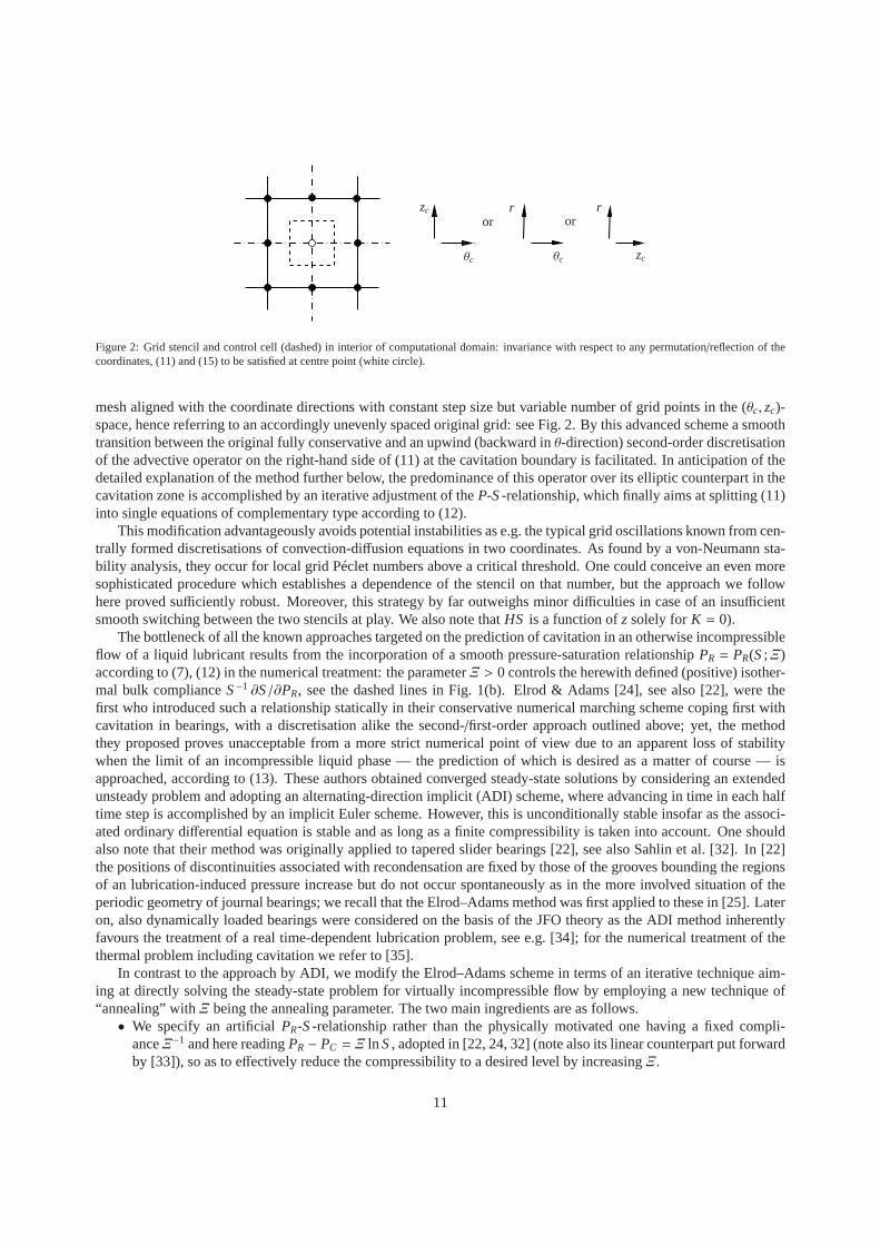
Figure 2: Grid stencil and control cell (dashed) in interiorof computational domain: invariance with respect to any permutation/reflection of thecoordinates, (11) and (15) to be satisfied at centre point (white circle).
mesh aligned with the coordinate directions with constant step size but variable number of grid points in the (θc, zc)-space, hence referring to an accordingly unevenly spaced original grid: see Fig. 2. By this advanced scheme a smoothtransition between the original fully conservative and an upwind (backward inθ-direction) second-order discretisationof the advective operator on the right-hand side of (11) at the cavitation boundary is facilitated. In anticipation of thedetailed explanation of the method further below, the predominance of this operator over its elliptic counterpart in thecavitation zone is accomplished by an iterative adjustmentof theP-S-relationship, which finally aims at splitting (11)into single equations of complementary type according to (12).
This modification advantageously avoids potential instabilities as e.g. the typical grid oscillations known from cen-trally formed discretisations of convection-diffusion equations in two coordinates. As found by a von-Neumann sta-bility analysis, they occur for local grid Péclet numbers above a critical threshold. One could conceive an even moresophisticated procedure which establishes a dependence ofthe stencil on that number, but the approach we followhere proved sufficiently robust. Moreover, this strategy by far outweighs minor difficulties in case of an insufficientsmooth switching between the two stencils at play. We also note thatHS is a function ofzsolely forK = 0).
The bottleneck of all the known approaches targeted on the prediction of cavitation in an otherwise incompressibleflow of a liquid lubricant results from the incorporation of asmooth pressure-saturation relationshipPR = PR(S;Ξ)according to (7), (12) in the numerical treatment: the parameterΞ > 0 controls the herewith defined (positive) isother-mal bulk complianceS−1 ∂S/∂PR, see the dashed lines in Fig. 1(b). Elrod & Adams [24], see also [22], were thefirst who introduced such a relationship statically in theirconservative numerical marching scheme coping first withcavitation in bearings, with a discretisation alike the second-/first-order approach outlined above; yet, the methodthey proposed proves unacceptable from a more strict numerical point of view due to an apparent loss of stabilitywhen the limit of an incompressible liquid phase — the prediction of which is desired as a matter of course — isapproached, according to (13). These authors obtained converged steady-state solutions by considering an extendedunsteady problem and adopting an alternating-direction implicit (ADI) scheme, where advancing in time in each halftime step is accomplished by an implicit Euler scheme. However, this is unconditionally stable insofar as the associ-ated ordinary differential equation is stable and as long as a finite compressibility is taken into account. One shouldalso note that their method was originally applied to tapered slider bearings [22], see also Sahlin et al. [32]. In [22]the positions of discontinuities associated with recondensation are fixed by those of the grooves bounding the regionsof an lubrication-induced pressure increase but do not occur spontaneously as in the more involved situation of theperiodic geometry of journal bearings; we recall that the Elrod–Adams method was first applied to these in [25]. Lateron, also dynamically loaded bearings were considered on thebasis of the JFO theory as the ADI method inherentlyfavours the treatment of a real time-dependent lubricationproblem, see e.g. [34]; for the numerical treatment of thethermal problem including cavitation we refer to [35].
In contrast to the approach by ADI, we modify the Elrod–Adamsscheme in terms of an iterative technique aim-ing at directly solving the steady-state problem for virtually incompressible flow by employing a new technique of“annealing” withΞ being the annealing parameter. The two main ingredients areas follows.• We specify an artificialPR-S-relationship rather than the physically motivated one having a fixed compli-
anceΞ−1 and here readingPR − PC = Ξ ln S, adopted in [22, 24, 32] (note also its linear counterpart put forwardby [33]), so as to effectively reduce the compressibility to a desired level by increasingΞ.
11
0
0.05
0.1
0.15
−5 −4 −3 −2 −1 0
0.2c1 = c∗1c1 = 4/3c1 = 2−4/3X−3
X
p1
(a)
0
2
4
6
8
0 0.5 1 1.5 2
10Ξ = 1Ξ = 5Ξ = 50
S
PR − PC
(b)
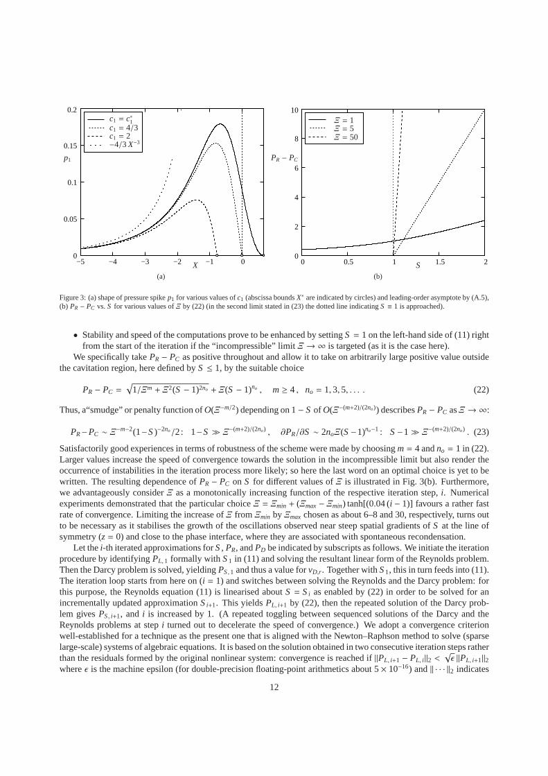
Figure 3: (a) shape of pressure spikep1 for various values ofc1 (abscissa boundsX∗ are indicated by circles) and leading-order asymptote by (A.5),(b) PR − PC vs.S for various values ofΞ by (22) (in the second limit stated in (23) the dotted line indicatingS ≡ 1 is approached).
• Stability and speed of the computations prove to be enhancedby settingS = 1 on the left-hand side of (11) rightfrom the start of the iteration if the “incompressible” limit Ξ → ∞ is targeted (as it is the case here).
We specifically takePR − PC as positive throughout and allow it to take on arbitrarily large positive value outsidethe cavitation region, here defined byS ≤ 1, by the suitable choice
PR − PC =√
1/Ξm + Ξ2(S − 1)2no + Ξ(S − 1)no , m≥ 4 , no = 1,3,5, . . . . (22)
Thus, a“smudge” or penalty function ofO(Ξ−m/2) depending on 1− S of O(Ξ−(m+2)/(2no)) describesPR − PC asΞ → ∞:
PR−PC ∼ Ξ−m−2(1−S)−2no/2: 1−S≫ Ξ−(m+2)/(2no) , ∂PR/∂S ∼ 2noΞ(S−1)no−1 : S−1≫ Ξ−(m+2)/(2no) . (23)
Satisfactorily good experiences in terms of robustness of the scheme were made by choosingm= 4 andno = 1 in (22).Larger values increase the speed of convergence towards thesolution in the incompressible limit but also render theoccurrence of instabilities in the iteration process more likely; so here the last word on an optimal choice is yet to bewritten. The resulting dependence ofPR − PC on S for different values ofΞ is illustrated in Fig. 3(b). Furthermore,we advantageously considerΞ as a monotonically increasing function of the respective iteration step,i. Numericalexperiments demonstrated that the particular choiceΞ = Ξmin + (Ξmax− Ξmin) tanh[(0.04 (i − 1)] favours a rather fastrate of convergence. Limiting the increase ofΞ fromΞmin byΞmax chosen as about 6–8 and 30, respectively, turns outto be necessary as it stabilises the growth of the oscillations observed near steep spatial gradients ofS at the line ofsymmetry (z= 0) and close to the phase interface, where they are associated with spontaneous recondensation.
Let thei-th iterated approximations forS, PR, andPD be indicated by subscripts as follows. We initiate the iterationprocedure by identifyingPL, 1 formally with S1 in (11) and solving the resultant linear form of the Reynoldsproblem.Then the Darcy problem is solved, yieldingPS,1 and thus a value forvD,r . Together withS1, this in turn feeds into (11).The iteration loop starts from here on (i = 1) and switches between solving the Reynolds and the Darcy problem: forthis purpose, the Reynolds equation (11) is linearised about S = Si as enabled by (22) in order to be solved for anincrementally updated approximationSi+1. This yieldsPL, i+1 by (22), then the repeated solution of the Darcy prob-lem givesPS, i+1, and i is increased by 1. (A repeated toggling between sequenced solutions of the Darcy and theReynolds problems at stepi turned out to decelerate the speed of convergence.) We adopta convergence criterionwell-established for a technique as the present one that is aligned with the Newton–Raphson method to solve (sparselarge-scale) systems of algebraic equations. It is based onthe solution obtained in two consecutive iteration steps ratherthan the residuals formed by the original nonlinear system:convergence is reached if||PL, i+1 − PL, i ||2 <
√ǫ ||PL, i+1||2
whereǫ is the machine epsilon (for double-precision floating-point arithmetics about 5× 10⁻¹⁶) and|| · · · ||2 indicates
12
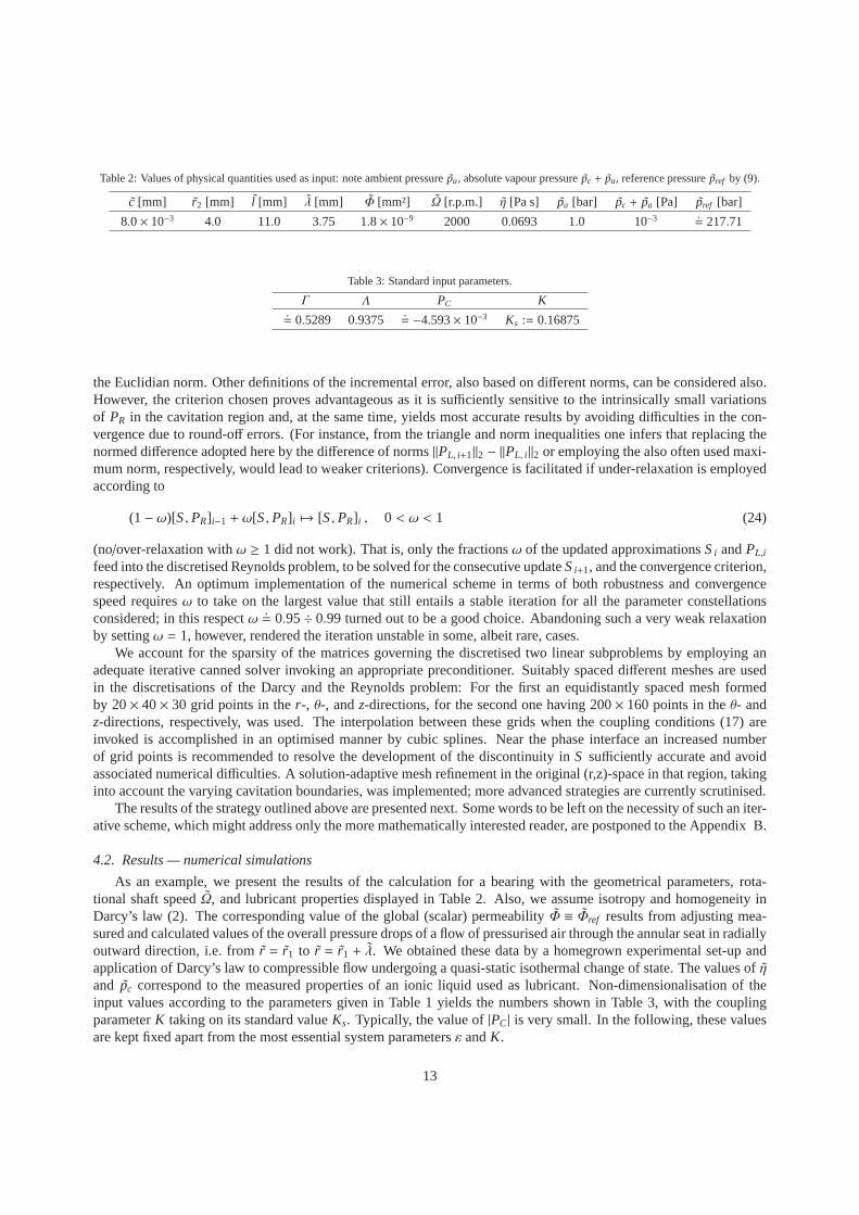
Table 2: Values of physical quantities used as input: note ambient pressure ˜pa, absolute vapour pressure ˜pc + pa, reference pressure ˜pref by (9).
c [mm] r2 [mm] l [mm] λ [mm] Φ [mm²] Ω [r.p.m.] η [Pa s] pa [bar] pc + pa [Pa] pref [bar]
8.0× 10⁻³ 4.0 11.0 3.75 1.8× 10⁻⁹ 2000 0.0693 1.0 10−3 .= 217.71
Table 3: Standard input parameters.
Γ Λ PC K.= 0.5289 0.9375
.= −4.593× 10⁻³ Ks := 0.16875
the Euclidian norm. Other definitions of the incremental error, also based on different norms, can be considered also.However, the criterion chosen proves advantageous as it is sufficiently sensitive to the intrinsically small variationsof PR in the cavitation region and, at the same time, yields most accurate results by avoiding difficulties in the con-vergence due to round-off errors. (For instance, from the triangle and norm inequalities one infers that replacing thenormed difference adopted here by the difference of norms||PL, i+1||2 − ||PL, i ||2 or employing the also often used maxi-mum norm, respectively, would lead to weaker criterions). Convergence is facilitated if under-relaxation is employedaccording to
(1− ω)[S,PR] i−1 + ω[S,PR] i 7→ [S,PR] i , 0 < ω < 1 (24)
(no/over-relaxation withω ≥ 1 did not work). That is, only the fractionsω of the updated approximationsSi andPL,i
feed into the discretised Reynolds problem, to be solved forthe consecutive updateSi+1, and the convergence criterion,respectively. An optimum implementation of the numerical scheme in terms of both robustness and convergencespeed requiresω to take on the largest value that still entails a stable iteration for all the parameter constellationsconsidered; in this respectω
.= 0.95÷ 0.99 turned out to be a good choice. Abandoning such a very weak relaxation
by settingω = 1, however, rendered the iteration unstable in some, albeitrare, cases.We account for the sparsity of the matrices governing the discretised two linear subproblems by employing an
adequate iterative canned solver invoking an appropriate preconditioner. Suitably spaced different meshes are usedin the discretisations of the Darcy and the Reynolds problem: For the first an equidistantly spaced mesh formedby 20× 40× 30 grid points in ther-, θ-, andz-directions, for the second one having 200× 160 points in theθ- andz-directions, respectively, was used. The interpolation between these grids when the coupling conditions (17) areinvoked is accomplished in an optimised manner by cubic splines. Near the phase interface an increased numberof grid points is recommended to resolve the development of the discontinuity inS sufficiently accurate and avoidassociated numerical difficulties. A solution-adaptive mesh refinement in the original (r,z)-space in that region, takinginto account the varying cavitation boundaries, was implemented; more advanced strategies are currently scrutinised.
The results of the strategy outlined above are presented next. Some words to be left on the necessity of such an iter-ative scheme, which might address only the more mathematically interested reader, are postponed to the Appendix B.
4.2. Results — numerical simulations
As an example, we present the results of the calculation for abearing with the geometrical parameters, rota-tional shaft speedΩ, and lubricant properties displayed in Table 2. Also, we assume isotropy and homogeneity inDarcy’s law (2). The corresponding value of the global (scalar) permeabilityΦ ≡ Φref results from adjusting mea-sured and calculated values of the overall pressure drops ofa flow of pressurised air through the annular seat in radiallyoutward direction, i.e. from ˜r = r1 to r = r1 + λ. We obtained these data by a homegrown experimental set-up andapplication of Darcy’s law to compressible flow undergoing aquasi-static isothermal change of state. The values of ˜η
and pc correspond to the measured properties of an ionic liquid used as lubricant. Non-dimensionalisation of theinput values according to the parameters given in Table 1 yields the numbers shown in Table 3, with the couplingparameterK taking on its standard valueKs. Typically, the value of|PC| is very small. In the following, these valuesare kept fixed apart from the most essential system parametersε andK.
13
In a first survey we variedε asK takes on the valueKs. Figures 4, 5 display the solutions for the pressure andsaturation for two distinct values ofε, namely,ε = 0.1 andε = 0.6. HerePR andS and thus the cavitation boundaryresults from interpolation of their data at the grid points.The minimum film thicknesses atθ = π obtained for thesecases, see (10), are 9µm and 4µm, respectively. Cavitation commences shortly downstreamof this location anddevelops in both the circumferential and the axial direction. The increase of the imposed loadL, i.e. ofε towards 1, isreflected essentially by the following four observations:
(A) PR exhibits a more abrupt change to the value ofPC,(B) S takes on considerably smaller values,(C) the cavitation boundary extends more closely to the edgeof the bearing,z= 1, in agreement with the picture
for ε close to 1 presented in Section Appendix A.3, and,(D) characterised by the position of spontaneous recondensation in the area slightly upstream ofθ = 2π, it moves
closer to this boundary from downstream.A local discontinuity or an at least more-or-less pronounced sharp rise ofS, associated with issue (D), is recordedfor all the values ofε andK yielding converged solutions, in perfect support of our theoretical considerations in Sec-tion Appendix A.5 forK = 0, at the least. We note that saturation secludes the regime of cavitation from downstreamin terms of a sudden jump even for any other parameter combination where convergence was achieved. On the basis ofthe present numerical results, this recurrent event can thus be safely considered as inevitable. The observations (A)–(D) also agree with the findings discussed in Section Appendix A.3. The question concerning the existence of thesolutions and a thresholdε∗ < 1 raised there is tied in with a likewise interesting one, namely, whether the reconden-sation front reachesθ = 2π for some value ofε below 1 or only finally in the limitε→ 1−. Currently, solutions areobtained only up to a value ofε situated near 0.9 (depending on the actual grid resolution and other numerical param-eters affecting the convergence behaviour) as by exceeding this value slightly we encounter a failure of convergence.This patently points to the existence of such a thresholdε∗ but the last word is not spoken yet.
In addition, we performed a parameter study where we vary gradually both the key quantitiesε and K. Theranges of their values were chosen so as to achieve the clearly visible separation of the curves along which they areheld constant: see Figs. 6–8. Herein the data indicated by the markers represent the results of the numerical study,interpolated smoothly by cubic splines. The only exceptionis the polar diagram showing the variation of the attitudeangleΨ in Fig. 6(b), where the markers are omitted as a much denser set of data points was used for generatingsufficiently smooth curves. The split of the plots into parts (a) and (b) in Figs. 7 and 8 targets at enhancing theirvisible resolution in terms of the ranges of the respective parameters forming the abscissae.
Table 4 displays the calculated values of the bearing load capacity or, equivalently, the Sommerfeld numberSofor the (otherwise fixed) configurations represented by the values in Table 3. The associated variation ofSo is alsoplotted in Fig. 6(a). Rather unsurprisingly, the load capacity generally decreases for increasing values ofK, wherethe impact of its variation on the load is more pronounced forlower values ofK and medium to high values ofε.The values ofK are chosen such that the load capacity approximately doubles for the most sensitive caseK = Ks.Finally, asK becomes quite large, the bearing loses its capacity of carrying the load, in agreement with the consider-ations put forward in Section Appendix A.6. From Fig. 6(b), one detects how changing the value ofK affectsΨ independence ofε, varied between 0 and the aforementioned threshold below which converged solutions were found.The (expected) rangeπ < Ψ ≤ 3π/2 reflects the occurrence of the pressure maximum and of cavitation in the, re-spectively, convergent (0< θ < π) and divergent (π < θ < 2π) parts of the bearing. In the case of an almost solidbearing (K = 0.001),Ψ exhibits a major change whenε is varied in its entire range, bounded by 0 and 1. We remarkthat for more porous bearings, this change is not so drastic,and the curve globally flattens. On the contrary,Ψ attainssmaller values the smallerK is in the limit ε→ 0, though we concede that the then intersecting curves can locally behardly distinguished from each other. Eventually, the analysis leading to (A.3) givesΨ = 3π/2 for K = 0 asε→ 0.
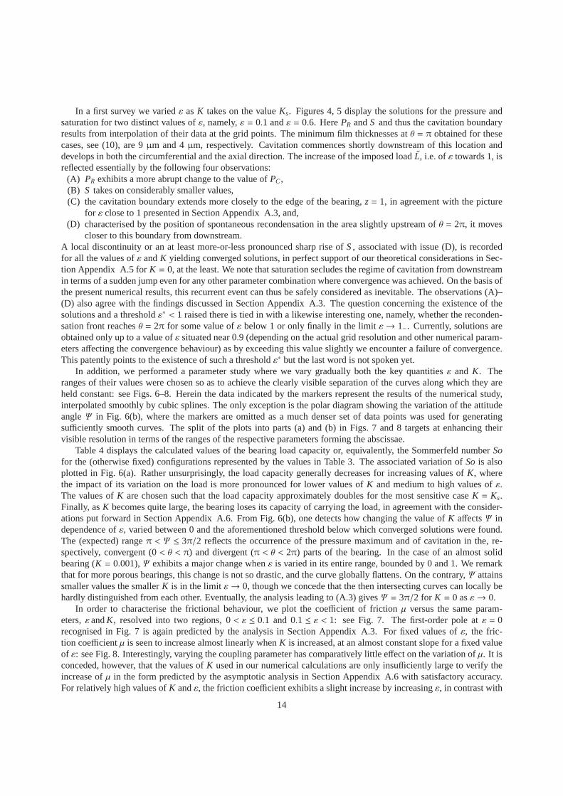
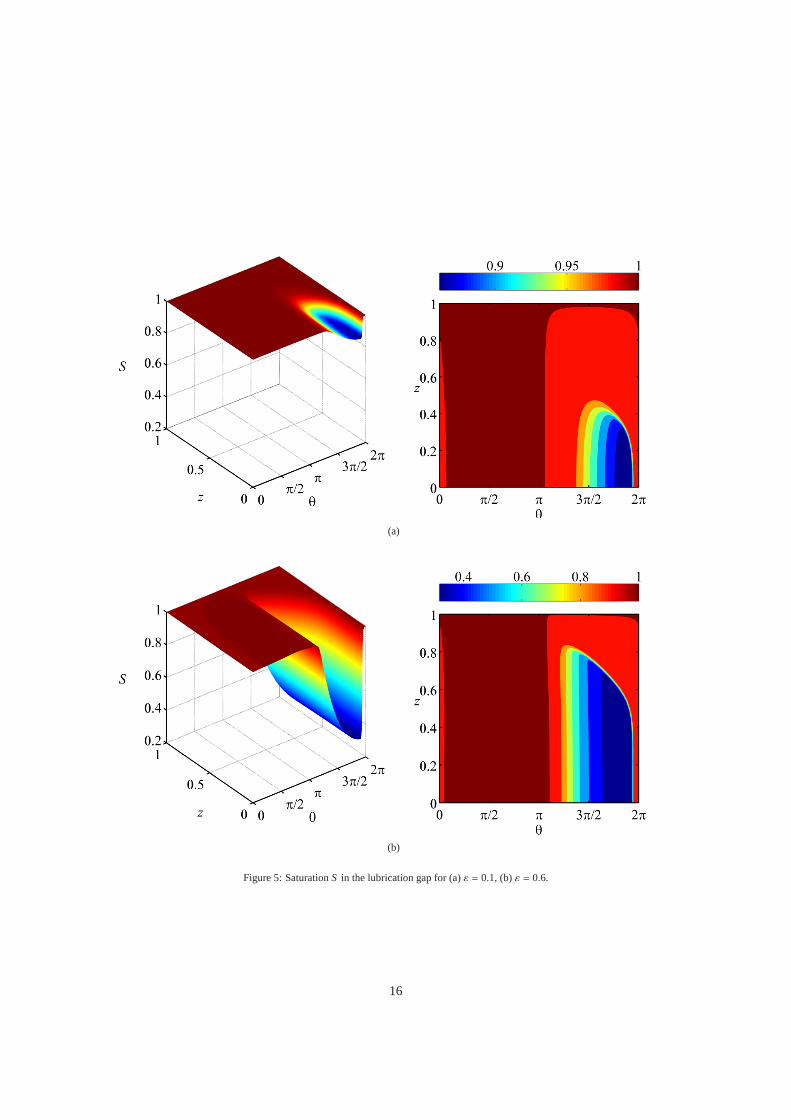
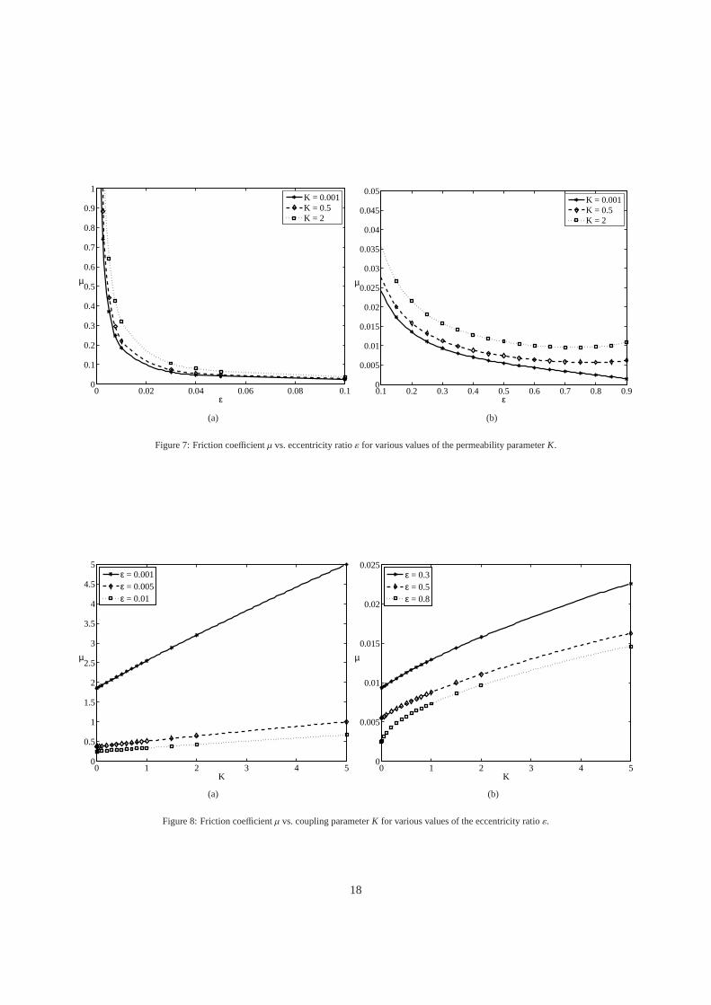
In order to characterise the frictional behaviour, we plot the coefficient of friction µ versus the same param-eters,εandK, resolved into two regions, 0< ε ≤ 0.1 and 0.1 ≤ ε < 1: see Fig. 7. The first-order pole atε = 0recognised in Fig. 7 is again predicted by the analysis in Section Appendix A.3. For fixed values ofε, the fric-tion coefficientµ is seen to increase almost linearly whenK is increased, at an almost constant slope for a fixed valueof ε: see Fig. 8. Interestingly, varying the coupling parameterhas comparatively little effect on the variation ofµ. It isconceded, however, that the values ofK used in our numerical calculations are only insufficiently large to verify theincrease ofµ in the form predicted by the asymptotic analysis in Section Appendix A.6 with satisfactory accuracy.For relatively high values ofK andε, the friction coefficient exhibits a slight increase by increasingε, in contrast with
14

(a)
(b)
Figure 4: PressurePR in the lubrication gap for (a)ε = 0.1, (b)ε = 0.6.
15
(a)
(b)
Figure 5: SaturationS in the lubrication gap for (a)ε = 0.1, (b)ε = 0.6.
16

Table 4: Rounded values of the Sommerfeld numberSo(bearing loadL [N]) for the standard values ofΓ, Λ, PC given in Table 3 and variableε, K.
ε Ks = 0.16875 K = 0.4 K = 0.6 K = 1 K = 1.2
0.1 0.0845 (51.56) 0.0791 (48.28) 0.0755 (46.06) 0.0695 (42.39) 0.0670 (40.87)0.2 0.1529 (93.31) 0.1413 (86.25) 0.1337 (81.58) 0.1213 (74.06) 0.1163 (70.97)0.3 0.2279 (139.09) 0.2075 (126.63) 0.1945 (118.72) 0.1743(106.37) 0.1662 (101.43)0.4 0.3159 (192.83) 0.2816 (171.89) 0.2610 (159.31) 0.2303(140.59) 0.2185 (133.36)0.5 0.4252 (259.55) 0.3676 (224.37) 0.3356 (204.87) 0.2910(177.62) 0.2744 (167.51)0.6 0.5675 (346.43) 0.4695 (286.57) 0.4210 (256.96) 0.3578(218.41) 0.3355 (204.78)0.7 0.7595 (436.58) 0.5920 (361.44) 0.5205 (317.71) 0.4339(264.88) 0.4047 (247.06)0.8 1.0212 (623.34) 0.7448 (454.66) 0.6429 (392.47) 0.5278(322.15) 0.4905 (299.41)
0.1
1.1
1
0.9
0.8
0.7
0.6
0.5
0.4
0.3
0.2
0 0.1 0.2 0.3 0.4 0.5 0.6 0.7 0.8ε
So K = 0.16875K = 0.4K = 0.6K = 1.0K = 1.2
(a)
270
300
330
360
Ψ
ε = 0.2
ε = 0.4
ε = 0.6
ε = 0.8
K = 0.001K = 0.2K = 0.7K = 1.8
(b)
Figure 6: (a) Sommerfeld numberSoand (b) attitude angleΨ [deg] vs. eccentricity ratioε for various values of the permeability parameterK.
the overall decreasing trend. This regime is of particular interest and subject to further investigations in the context ofthe existence of the aforementioned thresholdε∗ < 1.
4.3. Results — comparison with experiments
The study is completed by the presentation of some preliminary experimental results, serving as a starting pointfor a doubtless needful more elaborate validation of the proposed theoretical model and its numerical predictions.
From a traditional engineering point of view, an overview onthe behaviour of journal bearings under the differentconditions of lubrication (from mixed to fully hydrodynamic) is provided by plotting the friction coefficientµ versusthe rotational speedΩ for constant values of the applied bearing loadL, i.e. in terms of the celebrated Stribeck curves.Here only their fully hydrodynamic branch is of interest. Inpractice, the data required for such a plot are obviouslyquite accessible through adequately designed experimentsbut cannot be extracted directly from those obtained bysimulations: the latter are primarily parametrised by the varying eccentricity ratioε, which, however, is incapableof measurements by our experimental setup, rather thanL. Hence, correlating the data presented in Section 4.2 toexperimentally obtained ones requires their interpolation in terms ofL rather thanε by an advanced strategy thatmasters the inversion ofSogiven as a function ofε according to (19). To this end, smooth cubic-spline interpolationwas adopted to represent the functional dependences ofSoandµn on all the five parameters by fitting to their valuesused in both the experiments and the numerical calculations. Here the variation of the kinematic viscosityν := η/ρl
with temperature is implemented numerically on the basis ofthe classical empirical Ubbelohde–Walther formula:
17
0 0.02 0.04 0.06 0.08 0.10
0.1
0.2
0.3
0.4
0.5
0.6
0.7
0.8
0.9
1
ε
µ
K = 0.001K = 0.5K = 2
(a)
0.1 0.2 0.3 0.4 0.5 0.6 0.7 0.8 0.90
0.005
0.01
0.015
0.02
0.025
0.03
0.035
0.04
0.045
0.05
ε
µ
K = 0.001K = 0.5K = 2
(b)
Figure 7: Friction coefficientµ vs. eccentricity ratioε for various values of the permeability parameterK.
0 1 2 3 4 50
0.5
1
1.5
2
2.5
3
3.5
4
4.5
5
K
µ
ε = 0.001ε = 0.005ε = 0.01
(a)
0 1 2 3 4 50
0.005
0.01
0.015
0.02
0.025
K
µ
ε = 0.3ε = 0.5ε = 0.8
(b)
Figure 8: Friction coefficientµ vs. coupling parameterK for various values of the eccentricity ratioε.
18
lg lg(ν + f ) = a− b lg T involving ν [mm²/s], the absolute temperatureT [K] of the lubricant, lubricant-specific con-stants ˜a and b, and a correction factorf ( f
.= 0.7–0.8 for mineral oils). Let us finally emphasise that a comparison
between experimental and numerical data requires a satisfactory (long-term) running-in of the bearing in the regimeof fully hydrodynamic lubrication.
The experiments were carried out on sintered bearings with the geometrical parameters specified in Section 4.2,but with varying porosities, 20% and 25%, combined with two values of the supplied load: 10 N and 100 N. Thecasing weight adds up to the total load, such that the corresponding specific pressures are 0.5 N/mm², and 1.5 N/mm².Standard Stribeck tests involve both an acceleration regime as well as a deceleration one, where the rotational speedis varied gradually. The profiles are: 0–600 r.p.m. in 50 s, 600–3000 r.p.m. in 90 s, a constant regime at 3000 r.p.m.for 25 s, followed by a similar profile for a subsequent deceleration sweep. The measured temperature of the lubricantexhibits a slight monotonic dependence on the speed. For thereason stated at the end of last paragraph, merely theresults obtained during acceleration of the shaft rotationare used for the comparison. Three ionic liquids (ILx) withdifferent viscosity grades (VGy) were chosen as lubricants: IL1(VG32), IL2 (VG150), IL3 (VG220). Here the secondone is a binary volumetric 1:1-mixture of the other two each of which consists of just one salt component.
We discuss all four configurations of interest on the basis ofthe results shown in Figs. 9. The bold curves representthe output of a low-pass Gaussian filter applied to the raw measured data. Accordingly, the thin lines connecting theseoriginal data points are subject to pronounced oscillations indicating deviations from perfect steady-state conditionsin the experimental set-up. The curves referring to the simulations arise from smooth cubic-spline interpolation ofthe markers indicating the data obtained numerically. It appears that the best correlation between experiments andcalculations is observed in the case of lightly loaded bearings: Figs. 9(a,c,e). On the other hand, for quite high loads,the discrepancy between the two sets of data is accentuated:Figs. 9(b,d,f). The numerical results for a prescribedload confirm the findings inferred from (19), (20), (21) and (9) that the Sommerfeld numberSodecreases but thefriction force and, hence, the coefficient of frictionµ increase (almost linearly) when the rotational speedΩ increases:note thatµ decreases at a constant value of the latter for an increasingeccentricityε. The absence of data points insome regimes is due to the failure of the numerical interpolation scheme which for the given parameters yields valuescorresponding to the mixed lubrication domain. Nevertheless, at least for relatively low loads promising agreementis spotted, and the trends of the computed curves matches those of the measured ones satisfactorily well throughout.The apparent offset is most likely due to the serious uncertainty regarding the value of the permeability used in thesimulations and/or non-Newtonian effects. Concerning the role of the porosity in the frictional behaviour, a generalrule cannot be deduced from the rather small range of porosities available: the variation from 20% to 25% shows nonotable impact onµ. Note that Figs. 9(c,d) display the effect of mixing the lubricants used in the cases (a,b) and (e,f).
Complete geometrical similarity between different bearings means equal values ofΓ, Λ, and, as long as capillaryeffects are not considered, also ofK. It can often be assumed within a set of individual bearings of the same typebut different sizes with sufficient reliability. Due to the usually negligibly small variations ofPC, thenSoandµn
depend essentially onε solely. By eliminating this quantity, one ends up with the non-dimensional representationµn
versus 1/So (proportional to the Gümbel–Hersey number) of the Stribeckrelationship in the fully hydrodynamicregime, according to (19) and (9): see Figs. 10. Here only thedata for the pure ionic liquids are used as theirthermophysical properties ( ˜η, pc) are available at a higher accuracy. The collapse of the dataonto a single curveand a point in the (So, µn)-plane would indicate the conditions of complete geometrical and mechanical similarity,respectively. Therefore, future efforts in validation of the results of simulations include their careful evaluation by theirrepresentation in this particular form. As a consequence, the observed deviations of the measured data points fromthis universal relationship will serve as a measure to categorize the influence of additional effects, not yet consideredin our investigations.
5. Concluding remarks and further outlook
A mass-preserving model of vaporisation cavitation in the context of sintered journal bearings is proposed andstudied in terms of the reliability and consequences on a self-consistent description of the lubrication process theoret-ically, numerically, and, even if undeniably at a prematurelevel, also experimentally. By the new numerical techniqueadopted, we solved iteratively the system of equations, essentially consisting of the Reynolds and Darcy equationssupplemented with the Jakobsson–Floberg–Olsson condition for coping with the onset of cavitation and spontaneousrecondensation, with very high accuracy at comparatively little computational time and effort as the method directly
19

500 1000 1500 2000 2500 30000
0.02
0.04
0.06
0.08
0.1
Ω [r.p.m.]
µ
Experiment − originalExperiment − filteredSimulation
(a)
500 1000 1500 2000 2500 30000
0.02
0.04
0.06
0.08
0.1
Ω [r.p.m.]
µ
Experiment − originalExperiment − filteredSimulation
(b)
500 1000 1500 2000 2500 30000
0.05
0.1
0.15
0.2
Ω [r.p.m.]
µ
Experiment − originalExperiment − filteredSimulation
(c)
500 1000 1500 2000 2500 30000
0.05
0.1
Ω [r.p.m.]
µ
Experiment − originalExperiment − filteredSimulation
(d)
500 1000 1500 2000 2500 30000
0.05
0.1
0.15
0.2
0.25
Ω [r.p.m.]
µ
Experiment − originalExperiment − filteredSimulation
(e)
500 1000 1500 2000 2500 30000
0.02
0.04
0.06
0.08
0.1
Ω [r.p.m.]
µ
Experiment − originalExperiment − filteredSimulation
(f)
Figure 9: Data by experiments vs. by simulations for a bearing with a porosity of 20%, lubricated with IL1 (a,b), IL2 (c,d), IL3 (e,f), and under ashaft loadingL of 10 N (a,c,e), 100 N (b,d,f).
20

0 10 20 30 400
10
20
30
40
50
1/So
µn
20−10N
20−100N
25−10N
25−100N
(a)
0 20 40 60 80 100 1200
20
40
60
80
100
120
1/So
µn
20−10N
20−100N
25−10N
25−100N
(b)
Figure 10: Normalised friction coefficientµn vs. 1/S ofor IL1 (a) and IL3 (b); experiments/simulations: markers without/with connecting straightlines.
aims at predicting the steady-state operation of the bearing in straightforward manner, in contrast to previous ap-proaches. The main objective was to gain insight into the development of the lubrication pressure and saturation tiedin with the phase changes taking place inside the lubrication gap. Considering the benefit for engineering applica-tions, we believe that the — albeit showcase — numerical results offer encouraging perspectives into a successfulimprovement of existing tribological design of such bearings. In terms of the frictional behaviour, the comparisonbetween calculated and measured values of the friction coefficient discloses some discrepancies, but nonetheless alsoa promising trend.
Among the current and future demands of research activitiesalready outlined at the respective stages of this study,four tasks, viewed as primarily relevant, deserve to be highlighted as follows.
Measuring the phenomenon of cavitation in a sintered journal bearing is difficult and available data scarce, sothe validation of results by simulations to some extent subject to physical intuition yet. From this point of view, thenumerical study carried out in this work shows that the proposed model predicts satisfactorily well the phenomenonof cavitation for wide and feasible ranges of the varied key quantities in the space of the (five) dimensionless groupsinvolved, namely the eccentricity ratioε and the permeability parameterK. However, it appears that there existsa certain threshold forε for any fixed value ofK beyond which converged solutions of the lubrication problemdescribing stationary bearing operation cannot be achieved. Hence, the first task arises quite naturally: perturbationmethods along with homogenisation techniques can constitute the basis of future efforts meant to either numericallydetermine the associated boundaries in the parameter spacethat confine the regimes where solutions exist or stabilisethese in case their existence can be guaranteed for all values ofε exceeding this threshold, even in the limitε→ 1−. Inparticular,K is required to take on positive values in order to allow for the regularisation of the otherwise unboundedgrowth of the pressure spike near the position of minimum fluid film thickness, where the distinguished limitK → 0asε→ 1− poses the central problem currently under investigation. Eventually, microscopic effects due to surfaceroughness and porosity then come into play at leading order and, therefore, have to be accounted for in a rigorousextension of the current theory.
The second issue is associated with the saturation jump as one of the most notable predictions of the proposedflow description. Here the need for an elaborate effort both analytically and numerically is apparent in order to settlethe intriguing question whether the discontinuities remain or are smoothed out for finite values ofK. Specifically,the thorough investigation of rather weak jumps, associated with infinitesimally small cavitation regions, being thedistinguishing mark of certain parameter configurations and, in the present study, of lubricant flow referred to as amarginally cavitating one, is expected to shed light on the internal structure of the flow, which is of high interest even
21
if described still within the framework of classical lubrication theory.In the latter context the third question of utmost importance is raised, namely, which interfacial physical effects,
not addressed in the present study, have to be taken into account consistently in this regularisation process whenthe thickness of the resulting layer encompassing the cavitation boundary becomes correspondingly small asK → 0:there lubrication theory in the form adopted here needs to bemodified and extended accordingly.
Finally, the fourth subject presently under investigationconcerns the application of the homogenisation process tothe Reynolds problem, which then completes the self-consistent flow description of the two- (micro- and macro-) ormulti-scale approach.
In addition to the more severe shortcomings of the current theoretical approach and associated topics of researchaddressed above, it lacks, amongst other physical aspects of rather minor interest, the inclusion of non-Newtonianbehaviour of the lubricant and a sufficiently reliable prediction of the permeability in dependence of the measuredporosity. Resolving these issues would also contribute substantially to an improved model of cavitation. Unsteadyoperating conditions and/in combination with capillary effects represent further challenges worth to be met.
Notwithstanding the undeniably tremendous progress made towards a comprehensive understanding of the lubri-cant flow through self-lubricated journal bearings in the last decades and considering the vast amount of literature onthis subject, we believe the present work clarifies some of the hitherto unresolved aspects of (vaporisation) cavitationin such devices. Without doubt, much more has to be done in this direction not only analytically/numerically but alsoin terms of an experimental validation. This will certainlycreate added value for theoreticians as well as practitioners.
Acknowledgements
The authors would like to acknowledge the financial support of this research by the FP7 Marie Curie ActionsTraining NetworkMINILUBES and the Austrian Research Promotion Agency (FFG; grant no.:824187, projectacronym:XTribology). It was carried out at theExcellence Center of Tribologyat AC²T research GmbH. Also, welike to thank Dr. Stefan Eder (AC²T research GmbH) for exceptional discussions about the coding of the numericalscheme and his support regarding its implementation and thereviewers for their helpful comments. Special thanksgo to GKN Sinter Metals S.P.A. (Bruneck, Italy) for providing the authors with data referring to real (manufactured)bearings and supply of and technical assistance with an experimental rig.
Appendix A. Theoretical aspects
In the following, we outline the six points as raised in Section 3: Sections A.1–A.6.
Appendix A.1. Cavitation-free sinter flow
The formulation of (10)–(17) is self-consistent insofar asPD > PC is found for 1< r < 1+ Λ — otherwise agaseous phase would also take place in the seat and the application of Darcy’s law (2) and the adopted interpretationof vD,r obviously be in doubt. However, we now prove by considering smooth solutions of (15) in that region subjectto (16) that the above inequality is satisfied inside the seatandPD is equal toPC possibly only at its boundaryr = 1;cf. a related comment in [25].
Proof. Equation (15) is elliptic as the permeability componentsΦr, θ, z are positive, so thatPD assumes its extremalvalues at the outer boundaryr = 1+ Λ and/or in the limit r → 1 towards the inner boundary of the toroidal computa-tional domain that describes the sinter (which just restates the solenoidality of the velocity of the lubricant). That is,the solutionPD exhibits neither closed inner regions nor such confined by one of these boundaries wherePD < PC.As the only remaining possibility, such a region forms a single-connected tube that extends from the inner to theouter boundary and the facing sidesz := ±1 of the torus. ThenPD = PC on the generated surfaces of the tube andits intersection with the inner boundary. Consequently, the normal gradients ofPD at these bounding areas directedoutwards of the tube are positive throughout. Since they vanish identically at its intersection with the outer boundaryby (16), the values ofPD must take on a local minimum smaller thanPC inside that tube. However, this contradictsthe introductory statement and hence confirms that the occurrence of cavitation is restricted to the lubrication gap.
22
Appendix A.2. Mass deficit of active lubricant in loaded bearingInsulation of a fully submerged bearing exhibiting complete impregnation by an incompressible liquid lubricant
has an interesting side effect. The sinter is always soaked by the same amount of lubricant, independent of the specificoperating condition described by certain values of the parameters in Table 1. However, this is not necessarily true forthe lubrication gap: its volume is invariant with respect toa variation ofε, but not so are its fraction where cavitationoccurs, i.e.S < 1, and the specific distribution ofS therein.
The resulting mass deficit relative to the total mass of lubricant in the bearing has a magnitude of the order of theprincipal approximation error given by (4). We then conveniently introduce the ratioξ, ρv/ρl < ξ ≤ 1, of the actuallubricant mass in the gap to the constant one if cavitation was absent,
ξ(Γ, Λ,PC, ε,K) :=∫ 1
0
∫ 2π
0H(θ) S(θ, z) dθ dz
/ ∫ 1
0
∫ 2π
0H(θ) dθ dz=
12π
∫ 2π
0H(θ)
∫ 1
0S(θ, z) dzdθ . (A.1)
According to (8), then the equivalent volume or mass fraction containing the fully liquid phase is calculated from
12π
∫ 1
0
∫ 2π
0H(θ)αl(θ, z) dθ dz=
ξ − ρv/ρl
1− ρv/ρl. (A.2)
Varying the load in terms ofSoor, equivalently,ε as all other parameters in Table 1 are kept fixed allows for amost vivid interpretation of the mass defect in the lubrication gap. Thenξ accounts for the comparison of an unloadedbearing (ε = 0) with one where the applied load finally causes cavitation.Therefore, we haveξ = 1 for values ofthe load orε below certain thresholds indicating marginal cavitation.As confirmed by the numerical study, seeSection 4,ξ decreases if those quantities increase further. Under the assumption of an insulated bearing made in thepresent study, this mass deficit can be only unravelled by thepresence of the liquid rings that seal the bearing ends,as already mentioned in Section 2.2, and very thin liquid films covering the outer surface of the seat, both serving asadditional mass reservoirs: they apparently grow for an increasing load above the aforementioned critical value. Thishas to be confirmed in the course of a local analysis of the formation of these flow phenomena due to capillary andcentrifugal forces.
Appendix A.3. Limits of lightly- and heavily-loaded bearingsWe address some interesting aspects of the lubrication problem formulated in Section 2.2 for these two cases by
asymptotic analysis.
Appendix A.3.1. Very light loadingThe problem reflects the imposition of a sufficiently light bearing loadL in two different ways:1. Operating conditions and lubricant properties affect pref via Ω and η, see (9), and ˜pc. Under usual condi-
tions, this gives numerically rather small values ofPC. However, ˜pref can be so small, primarily due to acorrespondingly low rotational speedΩ, so that|PC| assumes an appreciable magnitude which includes thepossibility PC ≪ −1. But even in the — rather unconventional — latter casePR admits a finite limit that ap-propriately resolves the correspondingly weak variationsof p without provoking nucleation of a vapor cavity(marginal cavitation):S ≡ 1. Accordingly, so do the eccentricity ratioε and henceSo, the complementaryattitude angleΨ − 3π/2, andµn as given by (20), (21). In Section 4.1 it will turn out that this pathologic caserequires a separate numerical treatment (not addressed so far).
2. In contrast, one usually expects|PC| ≪ 1, in particular when novel promising lubricants as the ionic liquidsmentioned in Section 2.1 are in use. Then the common notion of“lightly-loaded” applies, namely the limitof vanishing eccentricity, i.e.ε ≪ 1 and an almost concentric gap by (10). This implies an expansion of theform PR ∼ εPR0(Γ, Λ, PC, K) +O(ε2), but cavitation-free flow, i.e.S ≡ 1, occurs only forε being sufficientlysmaller than|PC|. Accordingly, (20) and (21) then yield the Maclaurin expansion
[So/ε, Ψ, εµn] ∼ [
So0, Ψ0, µn0]
(Γ, Λ, K)+O(ε) with Ψ0(Γ, Λ, 0) = 3π/2 , µn0 = 3πc/(r2So0). (A.3)
Here the explicit expression forΨ0 arises from the familiar antisymmetry ofPR with respect toθ = π/2 for asubmerged massive bearing under the neglect of cavitation.Consequently, neglecting the contribution of thePoiseuille flow toµn yields the form ofµn0. Also, well-known Petroff’s law, cf. [36], pp. 483–484, is recoveredby this asymptotic representation. We add thatIC = π/
(
3√
1− ε2 )
if cavitation is neglected, i.e.αl ≡ 1 in (21).
23
Appendix A.3.2. Very heavy loadingWe appropriately address the opposite case of a heavily-loaded bearing by considering the limitδ := 1− ε→ 0.
For sufficiently small values ofδ, this finally has to take into account the aforementioned microscopic effects ofsurface roughness and surface porosity in the leading-order modification of the Reynolds equation as the homogeni-sation process adopted ceases to be valid in a small vicinityof the position where the gap heightH assumes itsminimum,θ = π/2. Specifically, these effects may become dominant in the region whereX :=
√δ (θ − π/2) = O(1)
and (10) is rewritten asH ∼ δh1(X) +O(δ2) with h1 := 1+ X2/2.In case of a massive bearing, i.e. forK = 0, this yields singular inner and outer expansions of the lubrication
pressure for, respectively,
X = O(1) : PR ∼ δ−3/2p1(X, z) +O(
δ−1/2) , θ − π = O(1) : PR ∼ PR1(θ, z) +O(δ) , (A.4)
with rescaled pressure distributionsp1, PR1 of O(1). Their match accomplishes the regularisation of a pressure spikenearθ = π/2 that grows beyond all bounds asδ→ 0: from (11), we find thatPR1 ∼ (4/3)(π − θ)−3 +O
[
(π − θ)−1] inthe limit θ → π−, whereasPR1 has to be found numerically for 0≤ θ < π andπ < θ ≤ 2π. Due to the disregard of theaforementioned effects, however, the functionp1(X, z) is still governed by the correspondingly reduced form of (11),where we additionally setS = 1. Integrated once, this givesh3
1 ∂p1/∂X = h1 − c1(z). It is the initially unknowncoefficient c1 that accounts for the regularisation and, by repeated integration overX from X = −∞, for the matchwith PR1 in terms of the upstream built-up of the pressure peak. This finally gives the analytical solution
p1(X, z) =[
4−3c1(z)]
X8h1(X)
+
√2
8
(
arctan( X√
2
)
+π
2
)
− c1(z)X4h1(X)2
∼ 43(−X)3
+O(
X−5)
as −X→ ∞ . (A.5)
Regarding theX-dependence ofp1, its deviation from its mean value is skew-symmetric. Forc1 > 1, p1 attains thedesired maximum and a minimum further downstream, atX∓(c1) := ∓
√2(c1 − 1). The minimum is positive/negative
if c1 is smaller/greater than a critical thresholdc∗1.= 1.225763, found by numerical evaluation of (A.5). Therefore,
the match ofp1 with variations ofPR of O(1) downstream ofθ = π demands the existence of an asymptotically smallflow region encompassing the locationX = X∗(c1) defined byp1(X∗, z) = 0 andp1(X, z) > 0 if X < X∗. This in turnrequiresc1 ≥ c∗1, and the aforementioned match is characterised by a zero or or negative gradient (∂P1/∂X)(X∗, z)for c1 = c∗1 with X∗ = X∓(c∗1) or c1 > c∗1 with X∗ < X+(c1), respectively. For the resulting distribution of the positivevalues ofp1 (whereX ≤ X∗) see Fig. 3(a). The maximum ofp1 decreases for increasing values ofc1. For c1 = 4/3,(A.5) reduces to the classical algebraic pressure distribution for a gap of parabolic shape [10]. Needless to say, herethe outer pressure functionPR1 andc1 depend parametrically onΓ, Λ, andPC. The following leading-order resultsare immediately found from (20), (21) and the above analysisfor
K = 0:[
δSo, µn/√δ]
∼ [
So1, µn1]
(Γ, Λ, PC) , Ψ ∼ π with
[
So1, µn1]
=
∫ 1
0
∫ X∗(c1)
−∞p1(X, z) ,
1So1
∫ X∗(c1)
−∞
23h1(X)
− c1(z)
2h21(X)
+1
So1
∫ ∞
X∗(c1)
S(θ, z)6h1(X)
dX dz.
(A.6)
One can easily express the integrals overX in closed forms.It is noted that the physical meaning of the small flow region addressed above lies in the description of the in-
evitable onset of cavitation. However, the associated completion of a perturbation theory coping with the associatedregularisation process in a self-consistent manner can notbe guaranteed for the time being: a preliminary analysisaiming at continuing the description of cavitating flow further downstream and towards the edge of the bearing whenviewed from a position where 0< X∗ − X = O(1) and values ofz> 0 not too close to 1 points to some subtle diffi-culties. This procedure essentially yields the form of the coefficient functionc1(z) and, hence,X∗(c1), as well as thevariation ofS in (A.6), which completes the flow description in the limitδ→ 0 for K = 0. The detailed splitting ofthe flow in the limit defined byK = 0, ε→ 1− as (θ − π)2/(ε + 1) = O(1) is subsumed as follows.
As a starting point of the analysis, one considers the core region defined by thin stripe 0< X∗ − X = O(1), z≥ 0,1− z≫
√δ where (A.5) holds. The functionc1(z) is determined by matching this core layer with the encompassing
flow regions up- and downstream of it, and a small square edge region where 1− z= O(√δ)
such that the left-handside of (11) is retained in full. In these regions (A.4) and (A.5) cease to be valid, and it is the last domain which
24
crucially accounts for the existence of a two-phase interface as cavitation cannot extend towards the bearing edgeif PC < 0, as assumed. Amongst others, then the following steps, here not given in all details, have to be performed:solving the leading-order lubrication problems arising inthese small regions subject to matching conditions in alldirections, then in the adjacent extended core region where0 < X − X∗ = O(1) andPR ∼ PC subject to the match withthe main region further downstream wherePR ∼ PR1, see (A.4). This finally establishes the desired form ofS in (A.6).
The current knowledge of the flow structure for a heavily-loaded, massive, insulated bearing can be condensedinto the statement that the existence of solutions for all values ofε satisfying 0≤ ε < 1 has to be doubted, at leastfor K = 0. At this stage the intriguing question arises whether solutions with S > 0 exist for all values ofε be-tween 0 (PR ≡ PD ≡ 0) and 1 or just forε ≤ ε∗ < 1 whereε∗ denotes a particular threshold. Its existence would pointto the loss of steady-state operation of the bearing even at finite loads or, equivalently, for a finite value ofSo. Onthe other hand, for finite values ofK a preliminary analysis shows that the singular limit studied here does not occur,which raises the expectation that forK > 0 solutions exist within the entire range 0≤ ε ≤ 1, so thatSo, Ψ − 3π/2,andµn attain finite limits asε→ 1−. Therefore, chances are high that the singularity characterising highly-loadedmassive bearings can be regularised by scrutinising a suitably defined distinguished limitK → 0 asǫ → 1−. However,such a local analysis as available at present is still not capable of answering the original question on the existence ofsolutions in the space spanned by the parameters given in Table 1. Settling this issue unambiguously is also beyondthe scope of the present study, but we revert to it in Section 4.2 in view of the numerical findings.
Appendix A.4. Weak singularity at inner corner of seat
The Darcy pressurePD canonically admits a weak logarithmic irregularity at the circle (r, z) = (1,1) where theinner surface of the seat, confining the gap, intersects withits facing side: see Fig. 1(a). As exposed subsequently, itemerges because the Neumann (insulation) boundary conditions in (16) holding at the latter is suddenly superseded bythe Dirichlet-type one, given by (14), at that corner. In turn, this singularity indicates that formulating the condition ofinsulation in such a way is probably too basic as its regularisation, necessitated on obvious physical grounds, requirestheir appropriate refinement, which e.g. takes into accountcapillary effects. However, the singularity is sufficientlyweak to be not considered in the numerical scheme, see Section 4.1.
Let [Φr 0, Φθ0, Φz0] := [Φr , Φθ, Φz](1, θ,1) define the (positive) values the permeability componentstake on at thatapex. We introduce local polar coordinatesR, ϑ by settingr − 1 = Rcosϑ, 1− z= γRsinϑ with γ :=
√
ΓΦz0/Φr 0 sothat the domain of the sinter in the vicinity of this corner isdescribed by 0≤ ϑ ≤ π/2 and Taylor expansions ofΦr, θ, z interms of sufficiently small values ofR. Then the problem (15)–(17) subject to the aforementioned Dirichlet boundarycondition assumes the following form in the coupled limits
R→ 0 , PD → 0:1R∂
∂R
(
R∂PD
∂R
)
+1R2
∂2PD
∂ϑ2∼ −Φθ0Φr 0
∂2PD
∂θ2+O(R) ,
∂PD
∂ϑ
∣
∣
∣
∣
∣
ϑ=0= 0 . (A.7)
The least-degenerate expression forPD is governed by the Laplacian on the left-hand side of the reduced form of (15)in (A.7). Hence,PD ∼ Re
[
(d1 ln ζ + e1)ζ +O(z2 ln ζ)]
+O(R3 ln R) ∼ R[
(d1 ln R+ e1) cosϑ − d1ϑ sinϑ)]
+O(R2 ln R),ζ := Rexp(iϑ), with some real functionsd1(θ), e1(θ) of O(1). At the inner edge of the seat given byr = 1 orϑ = π/2,this yields∂PD/∂r ∼ d1 ln s+ d1 + e1 +O(sln s) ass := 1− z→ 0+. Finally, we confirm the above remainder termsin the form of the Landau symbols by insertion of this expansion into (17) when combined with (11) and noticing theabsence of cavitation for the low pressure values in the limit
s→ 0+ : PR ∼ −πd1(θ) s/(2γ) +(
H′(θ) − K[
d1(θ)(ln s− 1/2)+ e1(θ)]
)
s2/ (
2H(θ)3)
+O(
s3 ln s, s3)
. (A.8)
That is,d1 ande1 appear as coefficients of eigenfunctions in the above expansions ofPD andPR. They have to bedetermined numerically as they depend on the solution of thefull lubrication problem (parametrised byK).
By exploiting the divergence form of the Reynolds equation (11) and the insulation conditions (16) one readily pre-dicts zero net mass fluxes across both ends of the bearing. Specifically, in the present configuration both contributionsvanish separately due to the assumed symmetry of the bearingwith respect toz= 0, giving
∫ 2π
0H(θ)3 ∂PR
∂z(θ, z) dθ =
∫ 2π
0H(θ)3d1(θ) dθ = 0 , (A.9)
25

but not necessarilyby a smooth continuation of the respective Neumann condition in (16) (as proposed by [25], forinstance). In other words, here these together with the global condition (A.9) express the preservation of mass ofthe lubricant impregnating the bearing, whereas no evidence is given for the more restrictive requirementd1 ≡ 0 ofa locally vanishing slope ofPR and hence vanishing mass flux at the bearing edge. That is, theoccurrence of thesingularity expressed by (A.8) is ruled out safely only in the degenerate casePC = 0 as well as the limiting oneK = 0,but where the corresponding one ofPD stays intact. However, since we have numerically 0< −PC ≪ 1 in generalcircumstances, we also expect that|∂PR/∂z(θ,1)| ≪ 1.
Appendix A.5. Does discontinuous recondensation prove unavoidable in self-lubricated journal bearings?
Guided by the local mass balance (18), we elucidated in Section 2.2 that for any constellation 0< ε < 1, 0≤ K ofthe two key parameters involved downstream saturation of the lubricantmaybe accompanied by the formation of asudden jump ofS and, accordingly, the pressure gradient. Without doubt, scrutinising this intriguing phenomenon ofspontaneous recondensation will contribute greatly to a deeper understanding of the mechanisms leading to cavitationin the form of partial vaporisation in general. Here its emergence is described by setting the left-hand side of theReynolds equation (11) identically to zero, according to (13). By taking into account that∂PD/∂r > 0 in this equation,cf. Section Appendix A.1, and that∂S/∂θ ≤ 0 at incipient vaporisation, we infer that the latter takes place in thediverging part of the gap (θ > π) and thatHS increases during cavitation of a fluid particle. Unfortunately, inspectionof (11) does not allow for a conclusive statement about the position or character of recondensation, in particular,whether the occurrence of discontinuities ofS and the gradient ofPR there are compelling.
However, forK = 0 at least, a different rationale given in form of a proof below outreaches itsforerunner pursuedin Section 2.2 which merely relies on the conditions (18) inasmuch it predicts the imperative (rather than just possible)occurrence of discontinuities inS. It is essentially based on the decomposition ofPR into a symmetric and an anti-symmetric part with respect to their dependence on the circumferential coordinateθ − π. We stress that consistentlycontinuous solutions cannot be ruled out for finite values ofK by the possibility of their regularising effect. On theother hand, the current numerical results give preference to inevitable discontinuities ofS even for moderate valuesof K at recondensation. We remark that so far this is found to takeplace slightly upstream ofθ = 2π throughout (seethe discussion of the solutions in Section 4.2).
Altogether, the introductory question raised in the headline of this section is not answered exhaustively at present.More both analytical and numerical efforts in this direction are required. We now come to its partial affirmation bythe aforementioned
Proof for K = 0. Assume the region of cavitation to lie symmetrically withrespect to the locationθ = π of a min-imum film thickness. As the productHS depends onz only, thenS = 1 in (18) holds at both ends of this region,indicating vaporisation and recondensation, due to the respective symmetry ofH(theta) (and, consequently,S(θ, z)).Furthermore, letPRs denote the likewise symmetric contribution toPR, governed accordingly by the homogeneouspart of (11) subject to homogeneous boundary conditions of the type (14). These are consistent with the require-ment of global conservation of mass as given by (A.9) and an analogous condition holding at the boundary of thecavitation zone inside which, due to the symmetry properties of the cavitation region,PRs is to be equated withPC,boundingPR and hencePRs from below. Outside of it, the governing homogeneous problem is elliptic, so it is evi-dent thatPRs exhibits no local extrema there; specifically, no maxima. Wethen arrive at the constraintPC ≤ PRs ≤ 0and, given the vanishing antisymmetric remainder contribution to PR in the region of cavitation, the rather unrealisticlimitationsPR ≡ PC ≡ 0 or, in the non-trivial casePC < 0 of concern,PC ≤ PR < −PC. But even for this situation theupper bound forPRs together with the above global condition of zero net mass fluxacross the bearing edge implieslocally vanishing mass flux there or∂PRs/∂z≡ 0 for z= 1 (and an analogous Neumann condition holding at the cav-itation boundary). Consequently, this gives againPRs ≡ PC ≡ 0. By this contradiction, symmetry and, equivalently,continuity ofS at recondensation on condition thatPC < 0 are ruled out.
The central argument of this proof rests upon the attempt to construct a not-identically vanishing symmetric contri-bution PRs to PR on the double-connected region that consists of the part of theθ, z-plane describing the unwrappedgap less the fully overlapped hole where cavitation occurs.If eitherε is sufficiently small so thatPR > PC throughoutor cavitation is simply neglected at all, that region is single-connected. As a consequence of the exploited extremalproperties ofPRs, this quantity then is identically zero. In this case the resulting antisymmetry ofPR with respect
26
to θ = π is of avail in fixing the solution in the singular limit of a very long bearing. As shown next, a more exhaustiveanalytical progress is possible then even if cavitation is taken into account.
Appendix A.5.1. Very long bearing:Γ ≪ 1ForΛ ≪ 1, we define the core region where 1− z= O(1) and thez-derivatives in (11) are correspondingly weak
and an edge layer characterised by 1− z= O(√Λ) where the full form of (11) is retained so that the solution in this
region can meet the Dirichlet boundary condition forz= 1 in (14). The properties of the resulting solution shall notbeof interest here in detail with the exception that it has to satisfy conditions of matching with its counterpart governingthe core region. Here we expandPR ∼ PR∞(θ) + o(1) where the drop of any (parametric)z-dependence ofPR∞ isargued differently depending on whether cavitation occurs or not. In the second case,PR∞ is easily found as an oddfunction with respect toθ = π by twice integration of (11) subject to the condition of an inθ cyclic solution, expressedthrough the classical Sommerfeld integrals for a fully submerged, infinitely long bearing, cf. [10]:
PR∞(θ) = J2(π, θ) − H∗J3(π, θ) , H∗ := J2(π,2π)/J3(π,2π) , Ji(a,b) :=∫ b
a
dτH(τ)i
(i = 2,3) . (A.10)
Any z-dependent additive contribution toPR∞ arising by integration is discarded in view of its antisymmetry requiredby the above findings concerning a bearing of finite length, here cast into conditions of formal matching with theleading-order solution in the edge layer. The extremal values of PR∞(θ) occur whereH(θ) takes on the valueH∗,which depends onε.
When cavitation shall be accommodated,z-independence ofPR∞ is due to the JFO condition taking on theforms (18). Specifically, inception of cavitation at some position θ = θc > π demandsPR∞(θc) = PC and simul-taneouslyPR
′∞(θc) = 0. This givesHS ≡ H∗ = H(θc) during cavitation further downstream, ending atθ = θr < π,
say. Hence, integrating (11) once recovers the JFO condition for (discontinuous) recondensation in (18) in theform PR
′∞(θr ) = 1/H(θr )2 − H(θc)/H(θr )3. Therefore, a further condition needed to determine bothθc andθr in depen-
dence ofε andPC must again be found by leading-order matching the pressure distributions in the core and the edgeregion. Regarding the latter, inspection of (11) forK = 0 subject to the boundary condition forz= 1 in (14) and (A.9)shows that the integral ofPR from θ = 0 to θ = 2π vanishes. By matching, this also holds for the core region, and theremaining condition is given by averagingPR∞ accordingly. Instead with (A.10), here one is finally concerned with
PR∞(θr ) = 0 ,∫ θc
θr
PR∞(τ) dτ + PC(π + θr − θc) = 0 as PR∞(θ) = J2(θc, θ) − H(θc) J3(θc, θ) , (A.11)
to be solved forθc andθr . We expectπ < θc < 2π and, by allowing recondensation to occur in the converging as wellas in the diverging part of the gap, 0≤ θr < π or −π < θr < 0. Problem (A.11) might also be of interest in the studyof marginal cavitation, by variation ofε.
Appendix A.5.2. Very short bearing:Γ ≫ 1The lubricant flow is less prone to cavitation if the bearing is relatively short. To put this in more precise terms,
in the limit Γ → ∞ inspection of (11) and (15) subject to (16) and (17) suggestsa decrease of the pressure describedby the expansionPD ∼ Γ−1P0(θ, r , z) +O
(
Γ−2) where ¯r := (r − 1)√Γ = O(1). Herein theθ-dependence ofS and the
functionP0 are only parametric as the lubrication problem reduces to
Φr (1, θ, z) ∂2P0/∂r
2 + ∂[
Φz(1, θ, z) ∂P0/∂z]
/∂z= 0 , (A.12)
subject to the periodicity and boundary conditions
[
P0, ∂P0/∂θ]
θ=0 =[
P0, ∂P0/∂θ]
θ=2π , ∂P0/∂z∣
∣
∣
z=0= P0
∣
∣
∣
z=1= P0
∣
∣
∣
r=∞ = 0 ,[
H(θ)3 ∂2(SP0)∂z2
− ∂(HS)∂θ
+ KΦr (1, θ, z)∂P0
∂r
]
r=1
= 0 ,
(A.13)
the last representing the correspondingly truncated form of (11), and constraints as given by (12) or (13). The analysisof the problem given by (A.12), A.13) has not been accomplished in full detail yet, but its route is outlined as follows.
27
Apart from the possiblez-dependence ofΦz, (A.12) represents Laplace’s equation. Therefore,its solution in termsof a Fourier series with respect toθ predicts exponential decay ofP0 when ¯r is large, so thatPS is correspondinglysmall in the main part of the seat wherer − 1 = O(1) as the thickness rationΛ is kept fixed. Accordingly, matchingof exponentially small terms then gives a reduced form of (15) subject to the Neumann boundary conditions in (16).We are thus confronted with a singular perturbation problem, which is regularised in case of a relatively slender seatwhere specificallyΛ = O
(
1/√Γ
)
. Then the conditions of insulation to be satisfied for a finitevalue of ¯r supersede theboundary condition at infinity in (A.13).
The flow described by (A.12), (A.13) is cavitation-free if 0< −PC ≪ 1/Γ (asS ≡ 1). Hence, a careful examina-tion of this problem in another distinguished limit, namelyPC = O
(
1/Γ)
, will shed light on the question addressedabove whether discontinuous recondensation occurs even for finite values ofK. This task is much easier to accom-plish than solving the full lubrication problem, even though still numerically to a major extent. Efforts in this directionare currently under way. The solutions then exhibit regionsof marginally cavitated flow if the value ofK is below acritical threshold. Hence, their systematic investigation is essentially attended by the variation ofK, besides that ofε.
Appendix A.6. Degenerate case of highly permeable seat: K≫ 1
A decoupling of the Reynolds from the Darcy problem (both problems then to be solved consecutively) accom-panies the regular limit processes governed byK → 0 as well as byK → ∞. In contrast to the former discussedalready extensively, however, in the latter the Darcy problem is solved first, as inferred from the predominance of thesource term, proportional toK, and the (forS ≡ 1 inhomogeneous) Couette term in the Reynolds equation (11)overits left-hand side. More precisely, we end up with the expansion [PD,PR] ∼ [P∞(r, θ, z),P∞(1, θ, z)]/K +O
(
1/K2) forlarge values ofK, where the accordingly reduced form of (11) provides an inhomogeneous type of Neumann bound-ary conditions complementing those of the form given in (16)for the leading-order problem governingP∞. In theso predicted flattening of the pressure variation the occurrence of (marginal) cavitation is conveniently described interms of a distinguished limit, namely, by varying the coupling parameterKPC, to be considered as a quantity ofO(1).Still the problem remains an involved nonlinear one as we allow S in the aforementioned Couette term entering theboundary condition to take on values smaller than 1 and thus being part of the solution by (13). The solution forP∞ isunique apart from a constant determined by the ambient pressure asP∞(r, θ,1) = 0. Finally, due to the pressure dropat a rate of 1/K and the then predominant Couette contribution to the gap flowthe bearing looses its load carryingcapability, whereas the friction factor remains finite as Petroff’s law is again valid, see (20), (21) and cf. (A.3), for
K ≫ 1: So∼ So∞(Γ, Λ,KPC, ε)/K +O(
1/K2) , µn ∼ 3π/So∞ +O(
1/K)
. (A.14)
The specific form of the functionSo∞ is determined by the parametric dependences ofP∞. Relations (A.14) demon-strate the usefulness of tackling the caseK ≫ 1 by perturbation methods.
The analysis of degenerate cases where the problems for the separate flow regions decouple is completed by men-tioning the assumption of a rather thin but at same time highly permeable seat, found to be described formally byanother distinguished limit process, different from that considered in Section Appendix A.5.2: letK := KΛ = O(1)when we haveΛ ≪ 1. We furthermore assume weak variations of the permeability components across the thick-ness of the seat in terms of their Maclaurin expansions with respect tor. In a specific extension of the analy-sis just outlined, we here cater to not only retaining the Couette term but also the left-hand side of (11) in itsleading-order approximation. Considering this last-degenerate limit, we find the lubrication pressurePR as repre-sented byP0(θ, z) + o(1). By the first of the conditions (17), the Darcy problem then suggests a regular expansion ofthe formPD ∼ P0(θ, z) + Λ2P2(r , θ, z) +O
(
Λ3) with r := (r − 1)/Λ and the coefficient functionsP0, P2 satisfying thesecond-order approximation of (15) readingΦr (1, θ, z) ∂r r P2 = D(θ, z) := −∂θ
[
Φθ(1, θ, z)∂θP0]
+ ∂z[
Φz(1, θ, z)∂zP0]
of (15). Integration with respect to ˆr by considering the conditions (16) of insulation yieldsΦr (1, θ, z) ∂r P2 = (r − 1)D.Now the above distinguished limit is suggested by insertingthe second of the conditions (17) into (11) as the lubrica-tion problem is finally cast into the following modification of the Reynolds problem:
∂
∂θ
[
Cθ(θ, z)∂P0
∂θ
]
+Γ∂
∂z
[
Cz(θ, z)∂P0
∂z
]
=∂(HS)∂θ
, Cθ, z := H(θ)3+ KΦθ, z(1, θ, z) ,∂P0
∂z
∣
∣
∣
∣
∣
z=0= P0
∣
∣
∣
∣
z=1= 0 , (A.15)
with P0 also subject to conditions of the type (13). Apart fromK, here the control parameters areΓ, ε, andKPC,advantageously considered as anO(1)-quantity. Then the problem posed by (A.15) may again serve as the outset for
28
studying marginal cavitation in a systematic manner. For isotropic and homogeneous permeability this problem wasalready considered in [37, 38] under the neglect of cavitation (S ≡ 1); in the latter study analytical progress possiblein the case of an infinitely long bearing and initiating an approximative solution in that of a three-dimensional onewas achieved. Hence, the need for intensified effort in studying (A.15) is apparent: condensing the Reynoldsand theDarcy problem into a single equation with essentially only two parameters governing the system behaviour involved(Kandε) is attractive. At first, it is interesting to see that the lubrication pressure and, consequently, the load bearingcapacity, i.e.So, remain finite when the seat becomes accordingly thin, in definite contrast to the prediction (A.14),which holds for (moderately) thick seats. It is remarked that the caseK ≫ 1 addressed above and that of a ratherimpermeable seat are formally included by this analysis when K ≫ 1 and 0≥ K ≪ 1, respectively. Therefore, theidea of studying (A.15) thoroughly definitely proves instructive from a more general viewpoint. Specifically, thisincludes answering the intriguing question whether solutions exists even in the limitε→ 1−.
For the implications and a discussion of specific results referring to the here addressed special cases we also referto the numerical study [2].
Appendix B. On the failure of an iterative scheme based on Gümbel-type boundary conditions
In a first manifest attempt to solve the lubrication problem for an incompressible liquid phase, the cavitationboundary is coped with iteratively in the spirit of the basicGümbel boundary conditions. It is instructive to focus onthe inherent failure of such a procedure.
Here pointed out without the inclusion of the Darcy problem for the sake of clarity, this approach suggests thefollowing steps: as a start, one solves the Reynolds problemby disregarding (12) and (18) and then, in the so foundregions wherePR > PC andPR ≤ PC, equatesS with 1 andPR with PC, respectively. Subsequently, the (downstream)portion describing recondensation of the closed boundary confining this region is updated by solving (11) under theneglect of its left-hand side. This is followed by the consecutive step, where the Reynolds problem is solved again butby prescribingPR = PC at that updated downstream confinement; the iteration in terms of repetitive steps becomesobvious at this point. However, convergence is doomed to fail for mainly two reasons: at first, (12) and (18) imposea weak ellipticity on the advection problem governingS in the cavitation region that cannot be accounted for bysolving the associated first-order degenerate form of (11) by downstream (or upstream) integration. Secondly, andeven more severe, the solution of an elliptic problem on a double-connected domain is intrinsically tied in with asingularity emerging in the extension of that region to a single-connected one. However, this cannot be coped with bythe numerical solution of the Reynolds problem based upon the above iterative scheme.
Let us underpin the last finding by considering the followingstandard Dirichlet problem in the Euclidian planeexpressed in polar coordinatesr, θ rather than giving a strict mathematical proof (employing Green’s function) for afunctionχ(r, θ) having periodicity 2π in θ,
0 < ρ < r < 1: ∆χ ≡ r−1 ∂(
r ∂χ/∂r)
/∂r + r−2 ∂2χ/∂θ2 = 0 ,
r = [1, ρ] : χ = [A0,a0] +∑∞
i=1rn
[An,an] cos(nθ) + [Bn,bn] sin(nθ)
.
(B.1)
Here the coefficientsAi , ai (i = 0,1, ...) andBi , bi (i = 1,2, ...), are assumed to be known. Then the unique solutionof (B.1) is given by
χ = A0+ (a0−A0)ln rln ρ+
∞∑
n=1
αn cos(nθ) + βn sin(nθ)ρ−n − ρn
, [αn, βn] :=
( rρ
)n
−(
ρ
r
)n
[An, Bn]− (
rn− r−n)[an,bn] . (B.2)
In the view of the lubrication problem considered here, the inner and outer boundariesr = ρ andr = 1 of the annu-lus 0≤ ρ < r ≤ 1 model the facing of the bearing and the cavitation interface. The corresponding boundary conditionsin (B.1) and the solution in (B.2) are expressed in terms of their Fourier representations and the resultant multi-poleexpansion (according to a Laurent series) around the originr = 0, respectively. This solution then captures the afore-mentioned difficulty as by revealing the presence of an essential singularity in the origin. In potential theory, thecoefficients of the logarithmic contribution and the term 1/r in (B.2) are interpreted as the integral flux 2πr∂χ/∂rand the strength of the dipole resulting from Green’s function. It is evident that analogous statements can be made forNeumann, Rubin, or accordingly mixed boundary conditions.
29

References
[1] Kumar V. Porous metal bearings — a critical review. Wear, 1980; 63(2):271–287.[2] Balasoiu AM, Braun MJ, Moldovan SI. A parametric study of aporous self-circulating hydrodynamic bearing. Tribology International, 2013;
61:176-193.[3] Morgan VT, Cameron A. Mechanics of lubrication in porous metal bearings. Proc. Conference on Lubrication and Wear, 1957; 151–157.[4] Neumann SP. Theoretical derivation of Darcy’s law. Acta Mechanica, 1977; 25(3/4):153–170.[5] Larson RG. Derivation of generalized Darcy equation forcreeping flow in porous media. Industrial & Engineering Chemical Fundamentals,
1981; 20(2):132–137.[6] Whitaker S. Flow in porous media I: a theoretical derivation of Darcy’s law. Transport in Porous Media, 1986; 1(1):3–25.[7] Kozeny J. Über kapillare Leitung des Wassers im Boden. Sitzungsbericht der Akademie der Wissenschaften, Wien, 1927;136(2a):271–306
(in German).[8] Scheidegger A. The physics of flow through porous media. University of Toronto Press, 1974.[9] Brinkman HC. A calculation of the viscous force exerted bya flowing fluid on a dense swarm of particles. Applied Scientific Research, 1949;
1A(1): 27–34.[10] Cameron A., Mc Ettles CM. Basic Lubrication Theory. Ellis Horwwood series in engineering science, West Sussex, 3rd revised ed., 1981.[11] Taylor GI. Cavitation of viscous fluid in narrow passages. Journal of Fluid Mechanics, 1963; 16(4):595–619.[12] Dowson D, Taylor CM. Cavitation in bearings. Annual Review of Fluid Mechanics, 1979; 11:35–66.[13] Swift HW. The stability of lubricating films in journal bearings. Proc. Institution of Civil Engineers (London), Minutes of the Proceedings,
Part 1, 1932; 233(1932):267–288.[14] Stieber W. Das Schwimmlager: Hydrodynamische Theorie desGleitlagers. V.D.I. Verlag GMBH, Berlin, 1933 (in German).[15] Floberg L. On Hydrodynamic Lubrication with Special Reference to Sub-cavity Pressures and Number of Streamers in Cavitation Regions.
Acta Polytechnica Scandinavica, Mechanical Engineering Series, vol. 19, The Royal Swedish Academy of Engineering Sciences, Stockholm,1965.
[16] Braun MJ, Hendricks RC. An experimental investigation of the vaporous/gaseous cavity characteristics of an eccentric journal bearing.ASLE Transactions, 1982; 27(1):1–14.
[17] Braun MJ. Cavitation formation and modelling for fluid filmbearings: a review. Proc. Institution of Mechanical Engineers, Part J: Journal ofEngineering Tribology, 2010; 224(9):839–863.
[18] Floberg L. Sub-cavity Pressures and Number of Oil Streamers in Cavitation Regions with Special Reference to the Infinite Journal Bearing.Acta Polytechnica Scandinavica, Mechanical Engineering Series, vol. 37, The Royal Swedish Academy of Engineering Sciences, Stockholm,1968.
[19] Cuvelier C. A free boundary value problem in hydrodynamic lubrication including surface tension. Lecture Notes in Physics (Proc. SixthInt’l Conference on Numerical Methods in Fluid Dynamics), 1979; 90:143–148.
[20] Savage MD. Cavitation in lubrication. Part 1. On boundary conditions and cavity–fluid interfaces. Journal of FluidMechanics, 1977;80(4):743–755.
[21] Savage MD. Cavitation in lubrication. Part 2. Analysisof wavy interfaces. Journal of Fluid Mechanics, 1977; 80(4):757–767.[22] Elrod HG. A cavitation algorithm. Journal of Lubrication Technology (Trans. ASME), 1981; 103:350–354.[23] Doerr N, Gebeshuber IC, Holzer D, Wanzenböck HD, Ecker A, Pauschitz A, Franek F. Evaluation of ionic liquids as lubricants. Journal of
Microengineering and Nanoelectronics (JMN), 2010; 1(1):29–34.[24] Elrod HG, Adams ML. A computer program for cavitation and starvation problems. Proc. 1st Leeds-Lyon Symposium on Tribology, Leeds
University, England, 1974; 37–41.[25] Meurisse MH, Giudicelli B. A 3D conservative model for self-lubricated porous journal bearings in hydrodynamic steady state. Journal of
Tribology (Trans. ASME), 1999; 121(3):529–537.[26] Neacsu IA, Scheichl B, Kluwick A. Nonlinear effects due to cavitation in self-lubricated bearings. Proc. Applied Mathematics and Mechan-
ics (PAMM), 2011; 11(1): 581–582.[27] Vázquez C. Existence and uniqueness of solution for a lubrication problem with cavitation in a journal bearing withaxial supply. Advances
in Mathematical Sciences and Applications, 1994; 4(2):313–331.[28] Bayada G, Chambat M, Vázquez C. Characteristics method for the formulation and computation of a free boundary cavitation problem.
Journal of Computational and Applied Mathematics, 1998; 98(2):191–212.[29] Bayada G, Martin S, Vázquez C. Two-scale homogenizationof a hydrodynamic Elrod–Adams model. Asymptotic Analysis, 2005; 44(1/2):
75–110.[30] Bayada G., Chambat M. On Interface Conditions for a Thin Film Flow Past a Porous Medium. SIAM Journal on Mathematical Analysis,
1995; 26(5):1113–1129.[31] Boukrouche M, Bayada G. Mathematical model, existence and uniqueness of cavitation problems in porous journal bearing. Nonlinear
Analysis: Theory, Methods & Applications, 1993; 20(8):895–920.[32] Sahlin F, Almqvist A, Larsson R, Glavatskih S. A cavitation algorithm for arbitrary lubricant compressibility. Tribology International, 2007;
40(8):1294–1300.[33] Dowson D, Higginson, GR. Elasto-hydrodynamic lubrication. Pergamon Press, Oxford, 1966.[34] Brewe, DE. Theoretical Modeling of the Vapor Cavitation in Dynamically Loaded Journal Bearings. Journal of Tribology (Trans. ASME),
1986; 108(4):628–638.[35] Mistry K, Biswas S, Athre K. Study of thermal profile and cavitation in a circular journal bearing. Wear, 1992; 159(1):79–87.[36] Shigley JE, Mischke CR. Mechanical Engineering Design. McGraw–Hill, New York, 1989.[37] Kumar A. Conical whirl instability of turbulent flow hybrid porous journal bearings. Tribology International, 1998; 31(2):235–243.[38] D’Agostino V, Senatore A. Analytical solution for two-dimensional Reynolds equation for porous journal bearings.Industrial Lubrication
and Tribology, 2006; 58(2):110–117.
30