a non-metallic casing spacer system
TRANSCRIPT

Leaders in Sealing Integrity
Ranger II®A Non-Metallic Casing Spacer System

Ranger II®
Leaders in Sealing Integrity2
NEW - RANGER II® GKO-XL Segments can support outside diameters up to 98.43". All Ranger II® casing spacers including Ranger II® GKO-XL are cost effective, completely non-metallic, being made entirely of polypropylene and can isolate the carrier pipe for a variety of applications. This includes being able to design Ranger II® casing spacers into a cathodic protection system.
APPLICATIONRoad crossing with casing pipe Carbon Steel and FRP, carrier pipe pre-insulated Carbon Steel and FRP.
TECHNICAL DESCRIPTION Carrier Pipe: Carbon Steel, FRP
Size of Carrier Pipe: DN 1200mm CS pipe - DN 750mm FRP pipe (pre-insulated)
Casing Pipe: FRP
Size of Casing Pipe: FRP casing pipe I.D. 1520mm, FRP casing pipe size I.D.
Go big with Ranger II® Casing Spacers
Ranger II®
Leaders in Sealing Integrity3
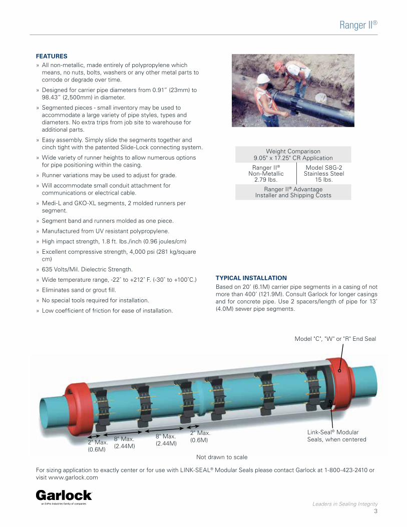
FEATURES » All non-metallic, made entirely of polypropylene which means, no nuts, bolts, washers or any other metal parts to corrode or degrade over time.
» Designed for carrier pipe diameters from 0.91” (23mm) to 98.43” (2,500mm) in diameter.
» Segmented pieces - small inventory may be used to accommodate a large variety of pipe styles, types and diameters. No extra trips from job site to warehouse for additional parts.
» Easy assembly. Simply slide the segments together and cinch tight with the patented Slide-Lock connecting system.
» Wide variety of runner heights to allow numerous options for pipe positioning within the casing.
» Runner variations may be used to adjust for grade.
» Will accommodate small conduit attachment for communications or electrical cable.
» Medi-L and GKO-XL segments, 2 molded runners per segment.
» Segment band and runners molded as one piece.
» Manufactured from UV resistant polypropylene.
» High impact strength, 1.8 ft. lbs./inch (0.96 joules/cm)
» Excellent compressive strength, 4,000 psi (281 kg/square cm)
» 635 Volts/Mil. Dielectric Strength.
» Wide temperature range, -22˚ to +212˚ F. (-30˚ to +100˚C.)
» Eliminates sand or grout fill.
» No special tools required for installation.
» Low coefficient of friction for ease of installation.
Weight Comparison9.05" x 17.25" CR Application
Ranger II® Non-Metallic
2.79 lbs.
Model S8G-2Stainless Steel
15 lbs.
Ranger II® AdvantageInstaller and Shipping Costs
TYPICAL INSTALLATION Based on 20’ (6.1M) carrier pipe segments in a casing of not more than 400’ (121.9M). Consult Garlock for longer casings and for concrete pipe. Use 2 spacers/length of pipe for 13’ (4.0M) sewer pipe segments.
Model "C", "W" or "R" End Seal
Not drawn to scale
Link-Seal® Modular Seals, when centered2" Max.
(0.6M)
8" Max.(2.44M)
8" Max.(2.44M)
2" Max.(0.6M)
For sizing application to exactly center or for use with LINK-SEAL® Modular Seals please contact Garlock at 1-800-423-2410 or visit www.garlock.com
Ranger II®
Leaders in Sealing Integrity4
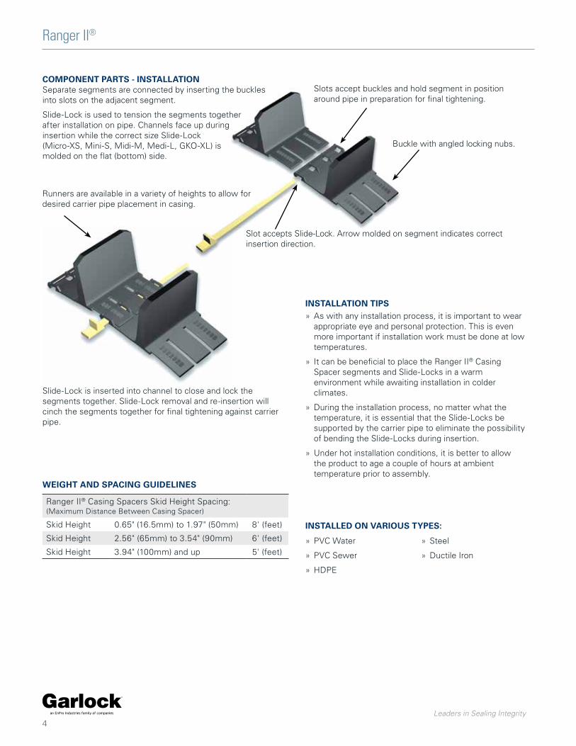
COMPONENT PARTS - INSTALLATIONSeparate segments are connected by inserting the buckles into slots on the adjacent segment.
Slide-Lock is used to tension the segments together after installation on pipe. Channels face up during insertion while the correct size Slide-Lock (Micro-XS, Mini-S, Midi-M, Medi-L, GKO-XL) is molded on the flat (bottom) side.
Slots accept buckles and hold segment in position around pipe in preparation for final tightening.
Buckle with angled locking nubs.
Slot accepts Slide-Lock. Arrow molded on segment indicates correct insertion direction.
Runners are available in a variety of heights to allow for desired carrier pipe placement in casing.
Slide-Lock is inserted into channel to close and lock the segments together. Slide-Lock removal and re-insertion will cinch the segments together for final tightening against carrier pipe.
INSTALLATION TIPS » As with any installation process, it is important to wear appropriate eye and personal protection. This is even more important if installation work must be done at low temperatures.
» It can be beneficial to place the Ranger II® Casing Spacer segments and Slide-Locks in a warm environment while awaiting installation in colder climates.
» During the installation process, no matter what the temperature, it is essential that the Slide-Locks be supported by the carrier pipe to eliminate the possibility of bending the Slide-Locks during insertion.
» Under hot installation conditions, it is better to allow the product to age a couple of hours at ambient temperature prior to assembly.
Ranger II® Casing Spacers Skid Height Spacing:(Maximum Distance Between Casing Spacer)
Skid Height 0.65" (16.5mm) to 1.97" (50mm) 8' (feet)
Skid Height 2.56" (65mm) to 3.54" (90mm) 6' (feet)
Skid Height 3.94" (100mm) and up 5' (feet)
WEIGHT AND SPACING GUIDELINES
INSTALLED ON VARIOUS TYPES:
» PVC Water
» PVC Sewer
» HDPE
» Steel
» Ductile Iron

Ranger II®
Leaders in Sealing Integrity5
Ranger II® Casing Spacers Skid Height Spacing:(Maximum Distance Between Casing Spacer)
Micro-XS Mini-S Midi-M Medi-L GKO-XL
Skid Height 0.65" (16.5mm) to 1.97" (50mm) 175 lb. 500 lb. 1,250 lb. 3,300 lb. 5,000 lb.
Skid Height 2.56" (65mm) to 2.95" (75mm) 135 lb. 400 lb. 1,000 lb. 2,600 lb. 4,000 lb.
Skid Height 3.54" (90mm) to 3.94" (100mm) 120 lb. 350 lb. 875 lb. 2,300 lb. 3,500 lb.
Skid Height 4.92" (125mm) to 5.91" (150mm) 250 lb. 625 lb. 1,650 lb. 2,500 lb.
Skid Height 6.89" (175mm) 500 lb. 1,400 lb.
RANGER II® CASING SPACERS SKID HEIGHT MAX LOAD PER SPACER
1.50(38)
1.42(36)
1.75(44)
1.97(50)
2.56(65)
2.95(75)
3.54(90)
5.91(150)
3.94(100)
4.92(125)
6.89(175)
1.10(28)
.65(16.5)
4.33(110)
Carrier Pipe O.D. Range Inches (mm)
Number of Segments Runner Height Options Inches (mm)
0.91 - 1.21 (23 - 31) 3
1.21 - 1.54 (31 - 39) 4
1.54 - 1.85 (39 - 47) 5
1.85 - 2.24 (47 - 57) 6
2.24 - 2.48 (57 - 63) 7
2.48 - 3.07 (63 - 78) 8
1.50(38)
1.97(50)
2.56(65)
2.95(75)
3.54(90)
3.94(100)
RANGER II® - MICRO-XS FOR 0.91 - 3.07” (23 - 78MM) DIAMETER CARRIER PIPE BAND WIDTH = 2.13” (54MM)
Carrier Pipe O.D. Range Inches (mm)
Number of Segments Runner Height Options Inches (mm)
2.61 - 3.26 (66 - 83) 4
3.26 - 3.93 (83 - 100) 5
3.93 - 4.57 (100 - 116) 6
4.57 - 5.51 (116 - 140) 7
RANGER II® - MINI-S FOR 2.61 - 5.51” (66 - 140MM) DIAMETER CARRIER PIPE BAND WIDTH = 3.15” (80MM)
1.50(38)
1.97(50)
2.56(65)
2.95(75)
3.54(90)
3.94(100)
4.92(125)
Verify that Slide-Locks match segment size by checking to ensure the segment name (Mini) matches the name molded on bottom of the Slide-Lock. Note: Micro & Mini segments both use the Mini Slide-Lock.
Verify that Slide-Locks match segment size by checking to ensure the segment name (Mini) matches the name molded on bottom of the Slide-Lock. Note: Micro & Mini segments both use the Mini Slide-Lock.
1.10(28)
.65(16.5)
Carrier Pipe O.D. Range Inches (mm)
Number of Segments Runner Height Options Inches (mm)
5.51 - 6.89 (140 - 175) 4
6.89 - 8.3 (175 - 211) 5
8.3 - 9.68 (211 - 246) 6
9.68 - 11.05 (246 - 281) 7
11.05 - 12.45 (281 - 316) 8
12.45 - 13.78 (316 - 350) 9
13.78 - 16.65 (350 - 423) 10
RANGER II® - MIDI-M FOR 5.51 - 16.65” (140 - 423MM) DIAMETER CARRIER PIPE BAND WIDTH = 5.12” (130MM)
Verify that Slide-Locks match segment size by checking to ensure the segment name (Midi) matches the name molded on bottom of the Slide-Lock.
1.50(38)
1.75(44)
1.97(50)
2.56(65)
2.95(75)
3.54(90)
5.91(150)
3.94(100)
4.92(125)
6.89(175)
1.10(28)
.65(16.5)
1.75(44)
4.33(110)
PROUDLYMADE IN THE
USA
PROUDLYMADE IN THE
USA

Ranger II®
Leaders in Sealing Integrity6
Carrier Pipe O.D. Range Inches (mm)
Number of Segments Runner Height Options Inches (mm)
16.77 - 20.00 (426 - 508)
4
20.00 - 25.98 (508 - 660)
5
RANGER II® - MEDI-L FOR 16.77 - 25.98” (426 - 660MM) DIAMETER CARRIER PIPE BAND WIDTH = 6.87” (174MM)
1.50(38)
1.97(50)
2.56(65)
2.95(75)
3.54(90)
3.94(100)
4.92(125)
5.91(150)
6.89(175)
Carrier Pipe O.D. Range Inches (mm)
Number of Segments Runner Height Options Inches (mm)
25.98 - 29.49 (660 - 749) 6
29.49-33.62 (749-854) 7
33.62-37.76 (854-959) 8
37.76-42.01 (959-1067) 9
42.01-47.20 (1067-1199) 10
47.20-52.36 (1199-1330) 11
52.36-56.69 (1330-1440) 12
56.69-60.63 (1440-1540) 13
60.63-65.35 (1540-1660) 14
65.35-70.87 (1660-1800) 15
70.87-75.20 (1800-1910) 16
75.20-80.39 (1910-2042) 17
80.39-84.65 (2042-2150) 18
84.65-89.37 (2150-2270) 19
89.37-94.49 (2270-2400) 20
94.49-98.43 (2400-2500) 21
RANGER II® - GKO-XL FOR 25.98 - 98.43” (660 - 2500MM) DIAMETER CARRIER PIPE BAND WIDTH = 8.86” (225MM)
1.42(36)
1.97(50)
2.56(65)
2.95(75)
3.54(90)
4.33(110)
4.92(125)
Verify that Slide-Locks match segment size by checking to ensure the segment name (Medi) matches the name molded on bottom of the Slide-Lock.
Verify that Slide-Locks match segment size by checking to ensure the segment name (GKO-XL) matches the name molded on bottom of the Slide-Lock.
1.10(28)
PROUDLYMADE IN THE
USA

Ranger II®
Leaders in Sealing Integrity7
SIZE YOUR INSTALLATION APPLICATIONAll Ranger II® Casing Spacers require more than one segment to complete a spacer. In addition, all Ranger II® Casing Spacers are available with a number of different runner height options which are used to guarantee clearance of the mechanical joint, provide for options in carrier pipe positioning within the casing or to compensate for grade elevation adjustments. Following are examples on how to size Ranger II® Casing Spacers for various applications. Detailed Ranger II® casing spacers weight & spacing guidelines on page 5. For exact centering and adjusting for grade elevation changes contact GPT.
EXAMPLE - CENTERED & RESTRAINED WITH EQUAL LENGTH RUNNERS20” Ductile Iron pipe (21.60” O.D. barrel & 28.63” O.D. bell) inside a 36” casing with a 0.375” wall thickness.A. Find carrier pipe O.D. (21.60”) from adjacent chart and choose the proper size and number of segments.One spacer would require 5 - Medi-L segments.B. Determine maximum runner height with equal length runners.
Casing I.D.Less Carrier Pipe O.D.
Less Space Allowance
35.25”-21.60”13.65”-1.00”12.65”
Divide this number (12.65”) by 2 to obtain the total maximum runner height = 6.325”C. Choose a runner height of this value or less. Solution: Use 5 - Medi-L (150) segments with runner heights of 5.91”.
NOTE: This combination will restrain the pipe from flotation within the casing pipe by allowing only about 1.8” of clearance be-tween the top runners and the casing I.D. This will center the carrier pipe within approximately 0.9” of exact center.
Bel
l O.D
.
Cas
ing
Pip
eI.D
.
Cas
ing
Pip
eO
.D.
EXAMPLE - TO CLEAR THE BELL(suggested minimum clearance is at least 0.8” (0.4” on both sides)20” Ductile Iron pipe (21.60” O.D. barrel & 28.63” O.D. bell) inside a 36” casing with a 0.375” wall thickness.Determine runner height. (Clear Bell)
Bell O.D.Add 0.8” Clearance
Less Barrel O.D.
28.63”+0.8”
29.43”-21.60”
7.83”
Divide this number (7.83”) by 2 to obtain the minimum runner height to clear the bell = 3.92” Choose a runner height between 3.92” and the maximum allowable runner height (6.32”) determined in the above example.Solution: Use 5 - Medi-L (100) segments with runner heights of 3.94”. Ordering Codes: See Back Page for Ordering Code Sequence.
Standard To Clear Bell Centered / Restrained
Min. 1” (25.4mm) clearance typical
For sizing application to exactly center or for use with LINK-SEAL® Modular Seals please contact Garlock at 1-800-423-2410 or visit www.garlock.com

Ranger II®
Leaders in Sealing Integrity8
NON-METALLIC CASING SPACER & END SEAL SPECIFICATIONS FOR CARRIER PIPE UP TO 98.43" O.D.Molded non-metallic technology enables Ranger II® casing spacers to replace existing specified stainless steel casing spacers.
A. Casing SpacersUpon installation of the steel pipe encasement, the contractor shall furnish and install a Ranger II® boltless casing spacer on the carrier pipe as described below. Casing spacers shall be spaced a maximum of eight (8)* feet apart along the length of the carrier pipe. Casing Spacers shall be used within two (2) feet of each end of the casing. For Bell Joints & other compression couplings, two additional spacers may be required per pipe joint. One spacer is required on either side of the pipe joint not to exceed 2ft from the joint itself. Wood skids are not an acceptable method of supporting the carrier pipe.
*Maximum spacing determined by skid height, reference table on page 4 for maximum spacing per skid height
1. Casing spacers shall be all non-metallic virgin polypropylene, molded in segments for field assembly without any special tools. Spacer segments shall be secured around carrier pipe by insertion of a Slide-Lock. The casing spacer polymer shall contain ultraviolet inhibitors and shall have a minimum compressive strength of 4,000 psi, 635 Volts/mil dielectric strength and impact strength of 1.8 ft-lbs./inch. Each casing spacer shall have full length, integrally molded skids extending beyond the bell or mechanical joint of the carrier pipe.
2. Spacers shall be at least as wide as listed below:
3. The casing spacers shall be the boltless/all non-metallic GPT Ranger II® Casing Spacers as manufactured by Garlock.
B. End SealsAfter insertion of the carrier pipe into the casing, the ends of the casing shall be closed by installing 1/8” thick synthetic rubber end seals equal to the Garlock Model C, W or R end seal as manufactured by Garlock.
CARRIER PIPE DIAMETER INCHES (MM) RANGER II® MODEL WIDTH INCHES (MM)
0.91 to 3.07” (23 to 78) Micro-XS 2.13” (54)
2.61 to 5.51” (66 to 140) Mini-S 3.15” (80)
5.51 to 16.65” (140 to 423) Midi-M 5.12” (130)
16.00 to 25.98” (406 to 660) Medi-L 6.87” (174)
25.98 to 98.43” (660 to 2500)
GKO-XL 8.86” (225)
BAND/RUNNER SEGMENTUV RESISTANT POLYPROPYLENE
SPECIFICATIONSCompressive Strength
VALUE4,000 psi (281 kg/sq. cm)
Temperature -22˚F to 212˚F (-30˚C to 100˚C)
Impact strength 1.8 ft. lb./in. (0.96 joules/cm)
Dielectric strength 635 volts/mil. min.
Color Black
Liner None
SPECIFIC MATERIAL CHART:

Ranger II®
Leaders in Sealing Integrity9
BASIC INSTALLATION PROCEDUREAlways wear protective safety glasses, especially in low temperatures.
1. Size the Ranger II® casing spacer to make sure you have all the segments and Slide-Locks.
3. Locate the directional arrows on the segment and insert Slide-Lock until the tip exits the end of the segment.
4. Continue the process from the previous step until all segments are put together. You’re now ready to wrap the Ranger II® around the pipe.
6. Insert all Slide-Locks as far as possible by hand. Complete tightening by tapping each Slide-Lock with a light rubber headed hammer.
7. To tighten Ranger II® securely to carrier pipe, back Slide-Lock completely out of the slot. If needed, push segments together by hand.
9. Repeat steps 7 and 8 until Ranger II® is secure against the carrier pipe and unable to move.
NOTE: Properly installed slide-locks will rarely be driven all the way in. To secure a tight fit drive as far as possible, but if all are driven completely, (bottomed out) it may not be tight enough. Verify Ranger II® casing spacer cannot slide on carrier pipe.
2. Take the segments and align the buckles. Insert the buckles 1/4 of the way into the slots. For GKO-XL position of the buckles (wedges) per element can be located in the table on following page.
5. Align the buckles and lock into place. Take the final Slide-Lock and slide into place.
NOTE: Make sure buckles are uniformly aligned and inserted into slots.
8. Re-insert Slide-Locks completely into segments by lightly tapping Slide-Lock back into position.
NOTE: Make sure buckles are uniformly aligned and inserted into slots.

Ranger II®
Leaders in Sealing Integrity10
RANGER II® GKO-XL WEDGE POSITIONING
PIPE OD GKO-XL NUMBER OF SEGMENTS
PER SPACER
POSITION OF WEDGES IN CONNECTING SECTION
FROM TO P1 P2 P3 P4
25.98 26.18 6 3 3
27.99 28.19 6 5 1
29.06 29.45 6 4 2
30.00 30.20 7 2 5
31.34 31.57 7 7
32.01 32.24 7 3 4
33.15 33.54 7 1 6
34.02 34.25 8 1 7
35.98 36.22 8 1 7
37.20 37.60 8 6 2
40.00 40.24 9 7 2
41.26 41.65 9 4 5
41.61 41.85 9 6 3
44.02 44.29 10 6 4
47.99 48.27 11 6 5
52.01 52.28 11 1 10
55.98 56.30 12 9 3
60.00 60.31 13 7 6
64.02 64.33 14 5 9
67.99 68.35 15 3 12
72.01 72.36 16 1 15
75.98 76.34 17 16 1
80.00 80.35 17 16 1
84.02 84.41 18 14 4
87.99 88.39 19 12 7
92.01 92.40 20 10 10
95.98 96.38 21 8 13
The recommendation position of GKO-XL wedges are suggestions only and can differ according to outside temperature.
GKO-XL WEDGE POSITION EXAMPLE
For a pipe O.D. of 30" put 2 wedges in position 3 and 5 wedges in position 2.
Ranger II®
Leaders in Sealing Integrity11
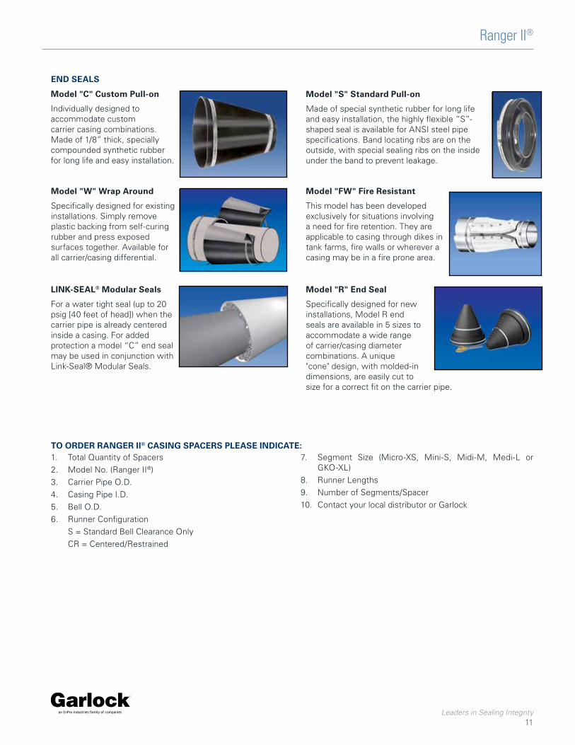
END SEALS
Model "C" Custom Pull-on
Individually designed to accommodate custom carrier casing combinations. Made of 1/8” thick, specially compounded synthetic rubber for long life and easy installation.
Model "W" Wrap Around
Specifically designed for existing installations. Simply remove plastic backing from self-curing rubber and press exposed surfaces together. Available for all carrier/casing differential.
Model "S" Standard Pull-on
Made of special synthetic rubber for long life and easy installation, the highly flexible “S”-shaped seal is available for ANSI steel pipe specifications. Band locating ribs are on the outside, with special sealing ribs on the inside under the band to prevent leakage.
Model "FW" Fire Resistant
This model has been developed exclusively for situations involving a need for fire retention. They are applicable to casing through dikes in tank farms, fire walls or wherever a casing may be in a fire prone area.
LINK-SEAL® Modular Seals
For a water tight seal (up to 20 psig [40 feet of head]) when the carrier pipe is already centered inside a casing. For added protection a model “C” end seal may be used in conjunction with Link-Seal® Modular Seals.
TO ORDER RANGER II® CASING SPACERS PLEASE INDICATE:1. Total Quantity of Spacers2. Model No. (Ranger II®)3. Carrier Pipe O.D.4. Casing Pipe I.D.5. Bell O.D.6. Runner Configuration
S = Standard Bell Clearance OnlyCR = Centered/Restrained
7. Segment Size (Micro-XS, Mini-S, Midi-M, Medi-L or GKO-XL)
8. Runner Lengths9. Number of Segments/Spacer10. Contact your local distributor or Garlock
Model "R" End Seal
Specifically designed for new installations, Model R end seals are available in 5 sizes to accommodate a wide range of carrier/casing diameter combinations. A unique "cone" design, with molded-in dimensions, are easily cut to size for a correct fit on the carrier pipe.

Tel: 1-877-GARLOCK / 315.597.4811 Fax: 800.543.0598 / 315.597.3216www.garlock.com
GARLOCKan EnPro Industries family of companies
GarlockGarlock AustraliaGarlock de Canada, LTDGarlock China
Garlock TaiwanGarlock SingaporeGarlock GermanyGarlock India Private Limited
Garlock de Mexico, S.A. De C.V.Garlock New ZealandGarlock Great Britain Limited
PSI 1-21_12.2020
ISO 9001 RegistrationEach casing spacer and end seal shall be manufactured at a facility that has a Registered ISO 9001 Quality Management System. Copy of current ISO 9001. Registration shall be provided with material submittal.
Warranty:All products are warranted against failure caused by manufacturing defects for a period of one year. Any product found to be so defective and returned within one year from date of shipment will be replaced without charge. The above warranty is made in lieu of, and we disclaim, any and all other warranties, expressed or implied, including the warranties of merchantability and fitness for a particular purpose, and buyer agrees to accept the products without any such warranties. We hereby disclaim any obligation or liability for consequential damages, labor costs or any other claims or liabilities of any kind whatsoever.