a new form of equations for rigid body rotational dynamics
TRANSCRIPT

A. A. Tikhonov i dr. Novi oblik jednadžbi rotacijskog gibanja krutog tijela
ISSN 1330-3651 (Print), ISSN 1848-6339 (Online) UDC/UDK 531.382:517.9
A NEW FORM OF EQUATIONS FOR RIGID BODY ROTATIONAL DYNAMICS Alexey A. Tikhonov, Cemal Dolicanin, Todor A. Partalin, Ivan Arandjelovic
Original scientific paper In the paper, a new form of differential equations for rigid body attitude dynamics is obtained. Three s-parameters (modified Rodrigues-Hamilton parameters) and three angular velocity parameters are used as unknown variables. Built equations are particularly useful for analytical and numerical study of rotational motion of a rigid body. The topological structure of configurational s-manifold for a balanced rigid body is investigated. An example of the use of constructed equations to describe the rotational motion of a rigid body in a resisting medium is considered. Keywords: dynamics, modified Rodriguez-Hamilton parameters, rigid body, rotational motion Novi oblik jednadžbi rotacijskog gibanja krutog tijela
Izvorni znanstveni članakU ovom je radu izveden novi oblik diferencijalnih jednadžbi koje opisuju dinamiku rotacijskog gibanja krutog (čvrstog) tijela oko središta njegove mase. Kao varijable koriste se tri s-parametra (modificirani parametri Rodriga-Hamiltona) i tri parametra kutne brzine tijela. Izvedene jednadžbe su osobito korisne za analitičko i numeričko izučavanje rotacijskog gibanja čvrstog tijela. Istražena je topološka struktura konfiguracijskog s-prostranstva za uravnoteženo kruto tijelo. Razmotren je primjer uporabe izvedenih jednadžbi koje opisuju rotacijsko gibanje krutog tijela u otpornoj sredini. Ključne riječi: dinamika, kruto tijelo, modificirani parametri Rodriga-Hamiltona, rotacijsko gibanje 1 Introduction
The studying of attitude motion of rigid body under the action of principle moment M
of external forces is
usually realized in terms of Euler angles, various variants of "aircraft" angles or direction cosines. The wide range of mechanical problems is connected with the studying of rotational motion of rigid body that is such attitude motion of the body with respect to the centre of mass C, when the work of moment M
of external disturbing
forces is small with respect to the kinetic energy of the body’s rotational motion.
These problems are usually investigated with the use of special variables. For example, the Andoyer (1862 ÷ 1929) dynamical equations of rigid body attitude motion are used widely in Beletsky-Chernousko variables
ϑψϕσρ ,,,,,L [1]:
,sin
sincoscossin1cosdd 21
22
ϑψψϕϕϑϕ
LMM
BACL
t+
+
−−=
,ctanctansincoscossind
d 22122
ρϑψψϕϕψL
ML
MMBA
Lt
−+
−
+=
,sincoscos sin sin11dd 12
LMM
BAL
tψψ
ϕϕϑϑ −+
−=
.sind
d ,dd ,
dd 21
3 ρσρ
LM
tLM
tM
tL
===
Here A, B, C are the body’s principal central
moments of inertia, L is the absolute value of kinetic moment L
, the angles σρ , determine the position of
vector L
and connected with it orthogonal Cartesian coordinate system 321C LLL with respect to the Koenig coordinate system XYZC according to Fig. 1, the Euler angles ϑψϕ ,, determine the orientation of the body’s
principal central axes of inertia zyx ,, with respect to the coordinate system 321C LLL , and M1, M2, M3 are the
projections of the moment M
on the axes of moving coordinate system 321C LLL .
The usability of these equations is connected with the constancy of vector L
(that is the values L, σρ, ) in
undisturbed motion of the body. But the computer simulation of mathematical models constructed with the use of Euler angles meets the following difficulties: 1) the kinematic equations degenerate at certain values
of angles; 2) the right parts of differential equations occur complex
trigonometric functions of angles, so the integration of these equations leads to significant increasing of computing time.
Figure 1 The coordinate system connected with vector L
The Euler-Poisson model based on the use of
direction cosines, is free of these disadvantages, but the closed system of equations in these variables has much higher order, so it is not convenient for computer modelling.
The above mentioned difficulties may be avoided by introducing new parameters. Among all kinematic
Tehnički vjesnik 21, 6(2014), 1221-1227 1221

A new form of equations for rigid body rotational dynamics A. A. Tikhonov et al.
parameters the significant place belongs to the Rodriguez-Hamilton parameters iλ (i = 0, 1, 2, 3) [2, 3]. They represent the components of 4-dimensional number
)( 3210 λλλλΛ ,,,= , called quaternion, and connected by
the normalization condition 123
22
21
20 =+++ λλλλ .
Choosing these parameters and dimensionless projections of angular velocity on principal central axes of inertia as variables we obtain in the normal form the system of seven differential equations (3 dynamical and 4 kinematic equations) for finding seven unknowns.
But the Rodriguez-Hamilton parameters are not minimal in number. The new parameters s1, s2, s3 (s-parameters) are introduced in the paper [4] for construction of the mathematical model of the body’s attitude motion. They possess the same advantages as the Rodriguez-Hamilton parameters and at the same time they are minimal in number. S-parameters may be considered as the result of stereographic projection of 4-dimensional sphere of quaternions, normalized with the condition
123
22
21
20 =+++ λλλλ , on 3-dimensional hyper plane,
orthogonal to the axis 0Oλ (Fig. 2).
Figure 2 S-vector as a result of stereographic projection
At the same time parameters si may be expressed in
terms of Rodriguez-Hamilton parameters according to the formula )1( 0λλ −= iis . The differential equations of the body’s attitude motion suitable for the investigation of the rotary motion were constructed in the paper [5] with the use of s-parameters. Later these equations were successfully used for the investigation of secular evolution of rotary motion of a charged satellite in a decaying orbit [6].
In this paper the new equations of the body’s attitude motion are deduced. They differ from analogous equations obtained in [5] with the use of variables
321 ,,,,, sssL σρ because instead of variables σρ ,,L we use the variables βαω ,, which determine the value and direction of the body’s angular velocity vector and more obvious in interpretation of the results of investigation. 2 The equations of motion
Let us determine the orientation of the body with the use of moving coordinates 321C ωωω (Fig. 3), where the axis 3Cω is directed along the vector ω of body’s angular velocity and CXYZ is the Koenig coordinate system.
Let us introduce the direction cosines matrix K of the axes ω1, ω2, ω3 with respect to the axes X, Y, Z:
βααβαββ
βααβαωωω
sin cossincos coscos0sin
sin sincoscos sin321
−−
ZYX
,
and the direction cosines matrix A of the body’s principle central axes of inertia x, y, z with respect to the axes ω1, ω2, ω3.
Figure 3 The coordinate system connected with vector ω The elements of matrix A can be expressed in terms of s-parameters s1, s2, s3 [4]:
0
22
210
0
1132
0
12313
0
1132
0
23
210
0
13212
0
1231
0
1321
0
23
220
1
)(8)2(4)2(4
)2(4)(8)2(4
)2(4)2(4)(8
ussu
uusss
uusss
uusss
ussu
uusss
uusss
uusss
ussu
zyx
+−+−
−+−+
+−+−
ω
ω
ω
, (1)
where
23
22
21
2 ssss ++= , ,)1( 220 += su 12
1 −= su . The following equations are valid:
,)()00( TTzyx ,,,, ωωωω A= (2)
.),,(),,( T321
TZ ωωω MMMMMM YX K=
The absolute angular velocity vector we represent in the form:
,re ωωω
+= (3)
where vector βαω
+=e is the angular velocity of the
coordinate system 321C ωωω , and vector rω
is the angular velocity of the body relative to the coordinate system 321C ωωω . Since T
3e2e1e )( ωωω ωωω ,, = T)cossin( βαββα ,,− then on the basis of (2) and (3) we
obtain: TTTrrr )cos sin ()( βαωββαωωω −−= ,,,, zyx A .
1222 Technical Gazette 21, 6(2014), 1221-1227
A. A. Tikhonov i dr. Novi oblik jednadžbi rotacijskog gibanja krutog tijela
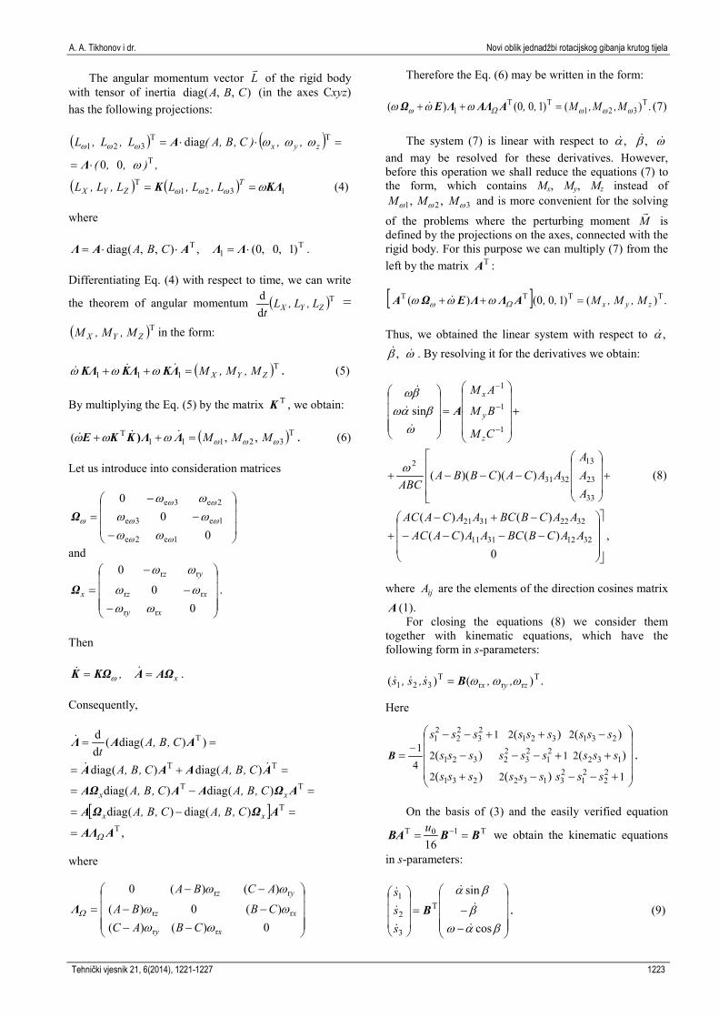
The angular momentum vector L
of the rigid body with tensor of inertia ),,(diag CBA (in the axes Cxyz) has the following projections: ( ) ( )
,),,(
,,)C,B,A(L,L,L zyx
T
TT321
00
diag
ω
ωωωωωω
⋅=
=⋅⋅=
Λ
A
( ) ( ) 1321T KΛK ωωωω == T
ZYX L,L,LL,L,L (4) where
T1
T )1,0,0(,),,(diag ⋅=⋅⋅= ΛΛAAΛ CBA . Differentiating Eq. (4) with respect to time, we can write
the theorem of angular momentum ( )Tdd
ZYX L,L,Lt
=
( )TZYX M,M,M in the form:
( )T111 ZYX M,M,M=++ ΛKΛKKΛ ωωω . (5) By multiplying the Eq. (5) by the matrix TK , we obtain:
( )T32111T ,,( ωωωωωω MMM=++ ΛΛKKE ) . (6)
Let us introduce into consideration matrices
−−
−=
00
0
1e2e
1e3e
2e3e
ωω
ωω
ωω
ω
ωωωωωω
Ω
and
−−
−
=0
0
0
rr
rr
rr
xy
xz
yz
x
ωωωω
ωω
Ω .
Then
x, AΩAKΩK == ω .
Consequently,
[ ],
)(diag)(diag
)(diag)(diag
)(diag)(diag
))(diag(dd
T
T
TT
TT
T
AAΛ
AΩΩA
AΩAAAΩ
AAAA
AAΛ
Ω=
=−=
=−=
=+=
==
xx
xx
C,B,AC,B,A
C,B,AC,B,A
C,B,AC,B,A
C,B,At
where
−−−−
−−
=0)()(
)(0)(
)()(0
rr
rr
rr
xy
xz
yz
CBACCBBA
ACBA
ωωωω
ωω
ΩΛ
Therefore the Eq. (6) may be written in the form:
.)()100()( T321
TT1 ωωωΩω ωωω M,M,M,, =++ AAΛΛEΩ (7)
The system (7) is linear with respect to ,α ,β ω
and may be resolved for these derivatives. However, before this operation we shall reduce the equations (7) to the form, which contains Mx, My, Mz instead of
,1ωM ,2ωM 3ωM and is more convenient for the solving
of the problems where the perturbing moment M
is defined by the projections on the axes, connected with the rigid body. For this purpose we can multiply (7) from the left by the matrix TA :
[ ] .)()100()( TTTTzyx M,M,M,, =++ AΛΛEΩA Ωω ωωω
Thus, we obtained the linear system with respect to ,α
,β ω . By resolving it for the derivatives we obtain:
, 0
)()()()(
))()((
sin
32123111
32223121
33
23
13
3231
2
1
1
1
−−−−
−+−+
+
−−−+
+
=
−
−
−
AACBBCAACAACAACBBCAACAAC
AAA
AACACBBAABC
CM
BM
AM
z
y
x
ω
ωβαω
βωA
(8)
where ijA are the elements of the direction cosines matrix A (1).
For closing the equations (8) we consider them together with kinematic equations, which have the following form in s-parameters:
.)()( Trrr
T321 zyx ,,s,s,s ωωωB=
Here
+−−−+
++−−−
−++−−
=−
122
212
221
41
22
21
23132231
13221
23
22321
23132123
22
21
)()(
)()(
)()(
sssssssss
sssssssss
sssssssss
B .
On the basis of (3) and the easily verified equation
T10T
16BBBA == −u we obtain the kinematic equations
in s-parameters:
−−=
βαωβ
βα
cos
sinT
3
2
1
Bsss
. (9)
Tehnički vjesnik 21, 6(2014), 1221-1227 1223

A new form of equations for rigid body rotational dynamics A. A. Tikhonov et al.
Thus, the system (8), (9) represents the differential system for description of the rotational motion of rigid body. This system is convenient for computer modelling because it has the unique singular point – the pole of function, mapping the unit sphere in 4-dimensional quaternion space onto the 3-dimensional hyperplane of s-parameters. But the direct hit of image point into the pole of mapping function during the motion is the exception case, demanding special initial conditions. The set of such initial conditions in the space of s-parameters has the zero measure and so the possibility of hitting the image point into the pole of mapping function practically does not realize.
3 The configurational manifold of s-parameters for
balanced rigid body
Let us consider the attitude motion of rigid body under the balanced external impact ( 0=M
). Such
attitude motion is characterized by the constant vector of angular momentum
TT )()(diag)( zyxzyx ,,C,B,AL,L,LL ωωω⋅==
and the constant value of kinetic energy
( ) . 00
0000
21
=
z
y
x
zyx
CB
A,,T
ω
ωω
ωωω (10)
On the basis of equation
, 00
T
=
ωω
ωω
A
z
y
x
(11)
we can express zyx L,L,L through ω :
=
=
33
32
31T
100
),,(diagCABAAA
CBAL ωω A
.
Consequently
)( 233
2232
2231
222 ACABAAL ++= ω . (12) Using (11) we can write (10) in the form:
. )(diag)(
100
)(diag)100(2
33
32
31
3332312
T2
=
=
=
AAA
C,B,AA,A,A
C,B,A,,T
ω
ω AA
Consequently
)(2 233
232
231
2 CABAAAT ++= ω . (13) Dividing (12) by (13) we obtain:
==++++
= DCABAAA
ACABAAT
L233
232
231
233
2232
2231
22
2const. (14)
We can write equation (14) in the form:
0)()()( 2233
2232
2231 =−+−+− CDCADBBADAAA . (15)
After substituting in Eq. (15) the elements of matrix
A , expressed through s1, s2, s3 , we obtain
.081
1216
1216
22
22
21
0
2221322
0
2222312
0
=−
+−+
+−−++
+−−−
)CDC()ss(u
)BDB())s(sss(u
)ADA())s(sss(u
(16)
The equation (16) represents itself the energy integral
of balanced rigid body, expressed in s-parameters. The fixed values of L and T determine the surface with implicit form (16) in the space of s-parameters. The constancy of angular momentum and kinetic energy of rotating balanced rigid body denotes that vector of s-parameters, defining the attitude position of the body at arbitrary moment, is on the mentioned surface. Consequently the surface (16) is the configurational manifold of balanced rigid body. It should be mentioned that the qualitative dependence of equation (16) on parameters s1, s2, s3 is just the same as that in analogous equation obtained in [5] (but the meaning of variables s1, s2, s3, is naturally another). In the paper [5] the configurational manifold of balanced rigid body was described by the equation
CA
BA
AA
LT 2
33232
231
22
++=
or, that is the same, by the equation
02121212
2332
2322
231 =
−+
−+
−
LT
CA
LT
BA
LT
AA .
Figure 4 Configurational manifold in s-parameters
1224 Technical Gazette 21, 6(2014), 1221-1227

A. A. Tikhonov i dr. Novi oblik jednadžbi rotacijskog gibanja krutog tijela
On the basis of (15) it follows that all conclusions made in [5] concerning the topological structure of configurational manifold and the s-vector boundedness remain in force. The example of trajectory obtained by numerical integration of equations (8), (9) at 0=M
is
shown in Fig. 4. It is evident that the trajectory coils on the bounded toroidal surface in the space of s-parameters.
In particular case then CBA ≠= , the system (8) - (9) is the following
−−
+−
=
0
)(sin 32123111
322231212AAAA
AAAA
ACAω
ωβαω
βω
, (17)
−−=
βαωβ
βα
cos
sinT
3
2
1
Bsss
. (18)
At that, as one might expect, we immediately obtain =ω const. from the third of equations (17). The energy
integral (15) takes the form:
0)())(( 2233
232
231
2 =−++− DCCAAADAA . In this case the configurational manifold is the regular tore, which has the following parametric representation with respect to the angles λ and γ :
.sinctan
),coscos1(sinsin
),coscos1(sincos
03
00
2
00
1
γθ
γθθλ
γθθλ
=
+=
+=
s
s
s
Here
[ ] [ ],,,, π20ππ ∈−∈ λγ and parameter [ ]2π00 /,∈θ is
defined by the equation ))((
)(2sin 02
DCACACDC
−+−−
=θ .
The example of trajectory coiling on the surface of such tore is obtained by numerical integration of equations (17), (18) and is shown in Fig. 5:
Figure 5 Configurational s-manifold for the case A=B
Figure 6 The trace of vector ω
on the unit sphere
The trace of vector ω
on the unit sphere, fixed in the
coordinate system XYZC , represents the circle (Fig. 6).
4 The example of the use of constructed equations
Let the body move in resisting medium, creating the disturbing moment ω
hM −= , proportional to the rigid
body angular velocity with coefficient 0>h . In projections on the axes zyx ,, we have
).(
),(),(
33
32
31
tAhM
tAhMtAhM
z
y
x
ω
ωω
−=
−=−=
(19)
where iA3 are the elements of direction cosine matrix A .
Consider the case CBA ≠= . Then the system (8), (9) take the form:
. cos
sin
,0
)(
sin
T
3
2
1
32123111
322231212
1
1
1
−−=
−−
+−
+
+
=
−
−
−
βαωβ
βα
ω
ωβαω
βω
B
A
sss
AAAAAAAA
ACA
CM
BM
AM
z
y
x
(20)
Below there are the results of numeric integration of
differential system (19) - (20) at initial conditions ,1)0(1 =s ,0)0(2 =s ,1)0(3 =s ,2)0( =ω ,0)0( =α
2π0 /)( =β and the parameters values ,3== BA 2=C . The trajectory of vector ω
in space of parameters
βαω ,, is shown in Fig. 7. The trajectory of vector ω
in coordinates zyx ,, is
shown in Fig. 8. In Fig. 9 we can see the trajectory of s-vector in space
s1, s2, s3. It is obvious that parameters 321 ,,,,, sssβαω are
convenient for computer modelling of rigid body motion
Tehnički vjesnik 21, 6(2014), 1221-1227 1225

A new form of equations for rigid body rotational dynamics A. A. Tikhonov et al.
Figure 7 Trajectory of vector ω in space βαω ,,
Figure 8 Trajectory of vector ω in space x, y, z
Figure 9 Trajectory of s-vector
5 Conclusions
In this paper a new form of differential equations for rigid body attitude dynamics is deduced. Three s-parameters (modified Rodrigues-Hamilton parameters) and three parameters which determine the value and direction of the body’s angular velocity vector are used as unknown variables.
The new equations are reminding the earlier obtained equations from [5] since both forms are based on the use of s-parameters, but the meanings of s-parameters are quite different. Another difference between these equations is that here we use the angular velocity variables instead of the angular momentum variables.
Such approach seems to be expedient as the angular velocity variables are more obvious in interpretation of the results of investigation. Built equations are particularly useful for analytical and numerical study of rotational motion of a rigid body.
The topological structure of configurational s-manifold for a balanced rigid body is investigated. The boundedness of s-vector in configurational space is shown. An example of the use of constructed equations to describe the rotational motion of a rigid body in a resisting medium is considered.
In future research, the authors will pay attention to the study of rotational motion of complex elements, such as [8, 9]. Also, in future work, the authors will be given to the study of new procedures and new effects [7, 10], that may be associated with the problems presented in this paper. Acknowledgement
The reported study was partially supported by the Russian Foundation for Basic Research, research projects No. 13-01-00347-a, No. 13-01-00376-a.
Parts of this research were supported by the Ministry of Sciences, Technologies and Development of Republic Serbia through State University of Novi Pazar and No. ON 44007. 6 References [1] Beletsky, V. V. The satellite’s attitude motion in
gravitational field, Moscow, 1975. [2] Branets, V. N.; Shmyglevsky, I. P. The use of quaternions
in the problems of rigid body orientation. Moscow, Nauka, 1973.
[3] Dolicanin, C.; Soloviev, Yu. P. Differential geometry. Prishtina, Grachanitsa, 1993.
[4] Marandi, S. R.; Modi, V. J. A preferred coordinate system and the associated orientation representation in attitude dynamics. // Acta Astronautica. 15, 11(1987), pp. 833-843.
[5] Petrov, K. G.; Tikhonov, A. A. The equations of rigid body rotational motion, based on quaternion parameters. // Proceedings of the Russian Academy of Sciences. Mechanics of Rigid Body. 3, (2000), pp. 3-16.
[6] Tikhonov, A. A. Secular evolution of rotary motion of a charged satellite in a decaying orbit. // Cosmic Research. 43, 2(2005), pp. 111-125.
[7] Dolićanin, C. B.; Antonevic, A. B.; Nikolic-Stanojevic, V. B.; Stanic, B. V. Contribution to the Orthogonal projection of H3 Space on to Orisphere and Introduction of Distance Method. // Scientific publications of the State University of Novi Pazar, Seria A. 3, 1(2011).
[8] Nikolić, V.; Dolićanin, Ć.; Dimitrijević, D. Dynamic Model for the Stress and Strain State Analysis of a Spur Gear Transmission. // Strojniški vestnik - Journal of Mechanical Engineering. 58, 1(2012), pp. 56-67.
[9] Nikolic-Stanojevic, V.; Veljovic, Lj.; Dolicanin, C. A New Model of the Fractional Order Dynamics of the Planetary Gears. // Hindawi Publishing Corporation, Mathematical Problems in Engineering. 2013, Article ID 932150, 15 pages, http://dx.doi.org/10.1155/2013/932150.
[10] Atanackovic, T. M.; Pilipovic, S.; Zorica, D. Vibrations of a System: Viskoelasic Rod of Fractional Type and a Body Attached to the Rod. // Scientific publications of the State University of Novi Pazar, Seria A. 4, 2(2012).
1226 Technical Gazette 21, 6(2014), 1221-1227

A. A. Tikhonov i dr. Novi oblik jednadžbi rotacijskog gibanja krutog tijela
Authors' addresses:
Alexey A. Tikhonov, Ph.D., Full professor (corresponding author) Saint-Petersburg State University 7-9, Universitetskaya nab. 199034 Saint-Petersburg, Russia E-mail: [email protected]
Ćemal Dolićanin, Ph.D., Full professor State University of Novi Pazar Vuka Karadzica bb, 36300 Novi Pazar, Serbia E-mail: [email protected]
Todor A. Partalin, Ph.D., associate professor Sofia University "St. Kliment Ohridski" 15 Tsar Osvoboditel Blvd., 1504 Sofia, Bulgaria E-mail: [email protected]
Ivan Arandjelovic, Ph.D., full professor Faculty of Mechanical Engineering Kraljice Marije 77, 11000 Belgrade, Serbia E-mail: [email protected]
Tehnički vjesnik 21, 6(2014), 1221-1227 1227