a new application of potassium nitrate as an
TRANSCRIPT

A NEW APPLICATION OF POTASSIUM NITRATE AS AN
ENVIRONMENTALLY FRIENDLY CLAY STABILIZER IN WATER-BASED
DRILLING FLUID
A Thesis
by
JING ZHOU
Submitted to the Office of Graduate and Professional Studies of
Texas A&M University
in partial fulfillment of the requirements for the degree of
MASTER OF SCIENCE
Chair of Committee, Hisham A. Nasr-El-Din
Committee Members, Mahmoud M. El-Halwagi
Sam Noynaert
Head of Department, A. Daniel Hill
May 2015
Major Subject: Petroleum Engineering
Copyright 2015 Jing Zhou

ii
ABSTRACT
The application of potassium chloride (KCl) as a temporary clay stabilizing
additive in water-based drilling fluids is problematic in chloride-sensitive formations.
However, failure to utilize clay stabilization leads to additional costs to drilling
operations due to wellbore stability and drilling fluid residual problems. In addition, the
chloride ions can be defined as a contaminant in land operations, with the potential to
inhibit the growth of vegetation and the potential to pollute aquifers. The purpose of this
study is to propose a new, high performance water-based fluid system using potassium
nitrate instead of potassium chloride as the clay stabilizing additive for drilling
applications.
Water-based drilling fluids using potassium nitrate and potassium chloride,
respectively, were prepared with a density of 1.3 S.G. using various weighting materials.
Capillary suction time (CST) test was used to optimize the potassium salt concentration
in drilling fluids for effective clay swelling inhibition. HPHT filtration tests under static
and dynamic conditions were conducted at 250°F and 300 psi. Berea sandstone cores
with an average porosity of 23 vol% and an average permeability of 50 md were used in
the filtration tests. The rheological properties, the volume of filtrate, and the filter cake
thickness of the water-based drilling fluids were determined and compared.
The CST tests show that potassium nitrate performs comparably to potassium
chloride as a clay stabilizer. However, the water-based drilling fluid containing
potassium nitrate has better rheological properties than that containing potassium

iii
chloride. The HPHT filtration press tests show that water-based drilling fluid with
potassium nitrate has a low filtration volume, less than 1 mL out of a total solution of
200 - 250 mL, when using barite as the weighting material. This paper not only
highlights the successful replacement of KCl by KNO3 to achieve good rheological
properties in water-based drilling fluids, but also shows that KNO3-based drilling fluids
are more economical as well as environmentally friendly than KCl-based drilling fluids
in drilling waste management.

iv
DEDICATION
To my family.

v
ACKNOWLEDGEMENTS
I would like to thank my committee chair, Dr. Nasr-El-Din, and my committee
members, Dr. El-Halwagi and Dr. Noynaert, for their guidance and support throughout
the course of this research.
Thanks also go to my friends and colleagues and the department faculty and staff
for making my time at Texas A&M University a great experience. I also want to extend
my gratitude to the survey instrument, and to all the Texas elementary teachers and
students who were willing to participate in the study.
Finally, thanks to my family for their encouragement, patience and love.

vi
NOMENCLATURE
CSC Critical Salt Concentration
CST Capillary Suction Time
HU Hounsfield Units
HPHT High Pressure/High Temperature
PHPA Partially Hydrolyzed Polyacrylamide/Polyacrylate
PV Plastic Viscosity
S.G. Specific Gravity
YP Yield Point

vii
TABLE OF CONTENTS
Page
ABSTRACT .......................................................................................................................ii
DEDICATION ..................................................................................................................iv
ACKNOWLEDGEMENTS ...............................................................................................v
NOMENCLATURE ......................................................................................................... vi
TABLE OF CONTENTS ................................................................................................ vii
LIST OF FIGURES .......................................................................................................... ix
LIST OF TABLES ......................................................................................................... xii
1. INTRODUCTION AND LITERATURE REVIEW .................................................. 1
1.1 Water-Sensitive Problems in Clay-Rich Reservoirs ................................................ 1 1.2 Clay Migration and Swelling Mechanism ................................................................ 1 1.3 Drilling Fluids and Clay Reactions .......................................................................... 3 1.4 Function of Potassium Salts in Drilling Fluids ........................................................ 4
1.5 Application of Potassium Chloride as Clay Stabilizer in Drilling Fluids ................ 6 1.6 Application of KNO3 to Replace KCl .................................................................... 12
1.6.1 Nitrate Used as Tracer Ion ............................................................................... 13 1.6.2 High Solubility of KNO3 at High Temperature ............................................... 13 1.6.3 Environmentally Friendly Drilling Fluids Using KNO3 ................................. 14 1.6.4 Drawbacks of KNO3 as an Alternative of KCl ................................................ 15
2. EXPERIMENTAL SETUP ...................................................................................... 16
2.1 Capillary Suction Test ............................................................................................ 16 2.2 Drilling Fluid Properties Test ................................................................................. 17 2.3 High-Pressure/High-Temperature (HPHT) Filtration Test .................................... 19 2.4 X-Ray Computed Tomography (CT) Scanning ..................................................... 20
3. EXPERIMENTAL PROCEDURES ........................................................................ 22
3.1 Capillary Suction Test ............................................................................................ 22 3.2 Drilling Fluid Properties Test ................................................................................. 23
3.3 HPHT Filtration Tests ............................................................................................ 26 3.4 X-Ray CT Scanning ............................................................................................... 27

viii
4. RESULTS AND DISCUSSION .............................................................................. 28
4.1 CST Test Results .................................................................................................... 28 4.2 Drilling Fluid Properties......................................................................................... 30 4.3 Filter Loss and Filter Cake Properties .................................................................... 33 4.4 CT Images Analysis ............................................................................................... 38 4.5 Land Farming of KNO3 Drilling Residuals............................................................ 46 4.6 Potassium Nitrate in a Double Salt Mixture .......................................................... 50
5. CONCLUSIONS ...................................................................................................... 53
REFERENCES ................................................................................................................. 55

ix
LIST OF FIGURES
Page
Fig. 1—Mechanisms of permeability reduction. (a) Migration, (b) Swelling, (c)
Swelling-Induced Migration. After Mohan et al. (1993). ................................... 3
Fig. 2—Effect of cation concentration and species on linear swelling. ............................. 9
Fig. 3—Effect of KCl and polymer solutions on linear swelling. .................................... 10
Fig. 4—Solubility of KNO3 and KCl. .............................................................................. 14
Fig. 5—Schematic diagram of a capillary suction timer. ................................................. 16
Fig. 6—CST timer (OFI Testing Equipment, Inc. 2014) ................................................. 17
Fig. 7—Fluid balance. ...................................................................................................... 17
Fig. 8—M3600 grace viscometer (Grace Instrument Industries LLC 2014) ................... 18
Fig. 9—HPHT filtration press (Fann Instrument Company 2015) .................................. 19
Fig. 10—X-Ray computerized tomography (CT) scanning. ............................................ 21
Fig. 11— The CST values change with the concentration of salt solutions. ................... 29
Fig. 12—Filter cake of KCl-based drilling fluid using barite as the weighting material
(Formula 1). ...................................................................................................... 35
Fig. 13—Filter cake of KCl-based drilling fluid using barite as the weighting material
(Formula 2). ...................................................................................................... 35
Fig. 14—Filter cake of KCl-based drilling fluid using Mn3O4 as the weighting
material (Formula 3). ........................................................................................ 36
Fig. 15—Filter cake of KCl-based drilling fluid using Mn3O4 as the weighting
material (Formula 4). ........................................................................................ 36
Fig. 16—Filter cake of KCl-based drilling fluid using ilmenite as the weighting
material (Formula 5). ........................................................................................ 36
Fig. 17—Filter cake of KCl-based fluid using ilmenite as the weighting material
(Formula 6). ...................................................................................................... 36

x
Fig. 18—Filter cake of KNO3-based drilling fluid using barite as the weighting
material (Formula 7). ........................................................................................ 37
Fig. 19—Filter cake of KNO3-based drilling fluid using barite as the weighting
material (Formula 8). ........................................................................................ 37
Fig. 20—Filter cake of KNO3-based drilling fluid using Mn3O4 as the weighting
material (Formula 9). ........................................................................................ 37
Fig. 21—Filter cake of KNO3-based drilling fluid using Mn3O4 as the weighting
material (Formula 10). ...................................................................................... 38
Fig. 22—Filter cake of KNO3-based drilling fluid using ilmenite as the weighting
material (Formula 11). ...................................................................................... 38
Fig. 23—Filter cake of KNO3-based drilling fluid using ilmenite as the weighting
material (Formula 12). ...................................................................................... 38
Fig. 24—CT scanned image for filter cake KCl-based drilling fluid using barite as the
weighting material (Formula 1). ....................................................................... 40
Fig. 25—CT scanned image for filter cake KCl-based drilling fluid using barite as the
weighting material (Formula 2). ....................................................................... 41
Fig. 26—CT scanned image for filter cake KCl-based drilling fluid using Mn3O4 as
the weighting material (Formula 3). ................................................................. 41
Fig. 27—CT scanned image for filter cake KCl-based drilling fluid using Mn3O4 as
the weighting material (Formula 4). ................................................................. 42
Fig. 28—CT scanned image for filter cake KCl-based drilling fluid using ilmenite as
the weighting material (Formula 5). ................................................................. 42
Fig. 29—CT scanned image for filter cake KCl-based drilling fluid using ilmenite as
the weighting material (Formula 6). ................................................................. 43
Fig. 30—CT scanned image for filter cake KNO3-based drilling fluid using barite as
the weighting material (Formula 7). ................................................................. 43
Fig. 31—CT scanned image for filter cake KNO3-based drilling fluid using barite as
the weighting material (Formula 8). ................................................................. 44
Fig. 32—CT scanned image for filter cake KNO3-based drilling fluid using Mn3O4 as
the weighting material (Formula 9). ................................................................. 44

xi
Fig. 33—CT scanned image for filter cake KNO3-based drilling fluid using Mn3O4 as
the weighting material (Formula 10). ............................................................... 45
Fig. 34—CT scanned image for filter cake KNO3-based drilling fluid using ilmenite
as the weighting material (Formula 11). ........................................................... 45
Fig. 35—CT scanned image for filter cake KNO3-based drilling fluid using ilmenite
as the weighting material (Formula 12). ........................................................... 46
Fig. 36—Steps for land farming of KNO3 drilling residuals. .......................................... 48
Fig. 37—The CST values of double salt mixtures (concentration, 4 wt%). .................... 52

xii
LIST OF TABLES
Page
Table 1— KCl-based drilling fluids with various formulas ............................................. 25
Table 2— KNO3-based drilling fluids with various formulas ......................................... 25
Table 3—CT scanning settings ........................................................................................ 27
Table 4—CST values of KCl and KNO3 ......................................................................... 29
Table 5—Rheological properties of KCl-based drilling fluids with various formulas .... 31
Table 6—Rheological properties of KNO3-based drilling fluids with various formulas . 32
Table 7—Experimental results of KCl-based drilling fluid HPHT static filter press ...... 34
Table 8—Experimental results of KNO3-based drilling fluid HPHT static filter press ... 34
Table 9—Average CT numbers of filter cakes ................................................................ 46
Table 10—Properties of some potential double salt mixtures. ........................................ 50

1
1. INTRODUCTION AND LITERATURE REVIEW
1.1 Water-Sensitive Problems in Clay-Rich Reservoirs
Water-sensitive clays undergo an ion-exchange process when insufficient
concentration of salt is present in the water. This salt insufficiency results in an
imbalance in their ionic stability leading to clay swelling, clay migration and even
breakdown of the rock structure (Bakly and Samir 2007). Conway et al. (2011) showed
that there are two factors, stabilizer type and concentration, which have a major impact
on the extent of clay stabilization. Investigation of water sensitive reservoir rocks began
nearly sixty years ago. The term “water sensitivity” refers to the phenomenon of
reduction in permeability caused by the swelling of indigenous clays or by the dispersion
and movement of indigenous particles.
1.2 Clay Migration and Swelling Mechanism
The majority of hydrocarbon producing formations contain clay minerals, and the
reaction of water (low salinity fluids) with these clay minerals tends to cause fines
dispersion and clay swelling.
Fines can be said to be small or tiny components of rock that can move within or
through pores of the rock. The characteristics of the fines migration vary with
mineralogy, morphology, abundance, and distribution. The phenomenon of colloidal

2
induced fines migration has significance in the petroleum industry as the release of these
fines can migrate and block pore throats causing formation damage thereby leading to
reduced production (Khilar et al. 1990). Clay minerals are especially susceptible to
migration because of their physical size and surface properties. According to Zhou et al.
(1995), most clay minerals (including silica and/or silicate sands) carry a negative
surface charge when immersed in aqueous solution of pH 5 or above. As a result of this
negative charge, clay particles detach themselves from the matrix, inducing migration
under hydrodynamic drag. Further experimental studies showed that fines migration is
affected by salt concentration, type and valence of cations, pH, flow rate, mineral
composition, and wetting status of fines.
As stated by Zhou et al. (1995), the hydration of interlayer cations and the
formation of diffuse double layers result in the expansion of structural layers, thereby
resulting in clay swelling. From many laboratory tests and field cases, clay swelling has
been continually proven to cause extreme damage to reservoir permeability. A concept
known as critical salt concentration (CSC) is found to exist in the water sensitivity of all
sandstones. In reservoir formations containing significant amounts of clay particles such
as smectite/montmorillonite, swelling of these clay particles is noticeable and causes
formation damage.

3
Fig. 1—Mechanisms of permeability reduction. (a) Migration, (b) Swelling, (c)
Swelling-Induced Migration. After Mohan et al. (1993).
1.3 Drilling Fluids and Clay Reactions
Historically, wellbore instability problems have occurred because of an
insufficient understanding the interaction between the drilling fluid and the clay
reactions (Bakly and Samir 2007).
Drilling fluids are a mixture of solids, liquids, and chemicals, with the liquid
being the continuous phase to stabilize the wellbore (Elkatatny et al. 2012). Various
drilling fluids have been suggested for dealing with troublesome water-sensitive
reservoirs. The nature of the clay/drilling fluids interface is strongly influenced by

4
physical and chemical interaction of solute species in the drilling fluid with the clay
surface and/or dilution of bound water by drilling fluid solvent (Schlemmer et al. 2003).
Unlike when drilling with oil-based drilling fluids, water-based drilling fluids
react with the formations (Kjøsnes et al. 2003). When drilling is expected to encounter
water-sensitive zones, the selection of the fluid becomes even more important. To
maintain a stable borehole through such zones, inhibitive drilling fluids will often be
required (O'Brien and Chenevert 1973).
1.4 Function of Potassium Salts in Drilling Fluids
The development of a water based drilling fluid that could effectively minimize
operational problems while drilling these wells was and continues to be a major
challenge (Donham and Young 2009). Oil-base fluids have been used to drill water-
sensitive formations, however, the use of oil-based drilling fluids is expensive and
present environmental problems, particularly for offshore use (Clark et al. 1976). The
use of oil-based drilling fluids also results in the discharge of contaminated cuttings
overboard, causing damage to benthic communities (Reid and Minton 1992).
Recently, potassium-based drilling fluids have become widely accepted for
drilling water-sensitive reservoirs which contain large quantities of smectite or
interleaved clays in the total clay fraction. Clay stabilizers are additives used in water-
based drilling fluid to prevent the swelling or migration reactions between water and
clay in pay zones. Cation exchange reactions can usually achieve an adequate degree of

5
clay stabilization. In the case of potassium enabled inhibition this is achieved by the
replacement of native sodium (Na+) and calcium (Ca+) by K+. The low hydration energy
and small size of the potassium ions enable K+ to fit into the gaps in the silica layers
within the clay crystal. K+ replaces Na+ and Ca+, becomes tightly fixed by attractive
forces, and binds the clay sheets together, thus reducing interlayer swelling. Compared
to available alternatives, lower cost, greater availability, and better thermal stability
favor the use of potassium salts.
The benefits of potassium ions in suppressing the hydration and swelling of clay
minerals have long been recognized and applied in drilling (Mondshine 1973). The
native potassium ions (K+) attach to clay surfaces and lend stability to reservoir rocks
exposed to drilling fluids by the bit. The ions also help hold the cuttings together,
minimizing dispersion into finer particles.
Potassium ions retard the expansion of swelling clay (smectites) and, hence, of
shales containing these minerals. High salt levels also promote clay flocculation by
collapsing extended electrical double layers. The superiority of potassium in this role is
due to the size and low hydration energy of the potassium ion. Potassium can enter into
the clay lattice, forcing ejection of connate water, become tightly fixed by attractive
forces, and thus bind the clay sheets together. The use of potassium as an exchange ion
to stabilize drilled shales has been accepted worldwide. Potassium is an effective clay
swelling/hydration inhibitor, where the concentration of potassium to achieve the desired
result is often a function of the shale being drilled. The potassium ion replaces native
sodium and calcium ions in clay to prevent hydration of the clay. Potassium is widely

6
used internationally, and comes from many sources, including potassium chloride,
potassium carbonate, potassium acetate, and potassium hydroxide. However, the
formation will be damaged from filtrate invasion of potassium formate drilling fluids.
1.5 Application of Potassium Chloride as Clay Stabilizer in Drilling Fluids
Potassium chloride (KCl) is often used as the supply of potassium in water-based
drilling fluids. The chloride ion however can be defined as a contaminant in land
operations, with the potential to inhibit the growth of vegetation, and it can also be
considered a potential pollutant to aquifers (Dow et al. 2012).
The KCl/polymer system was developed to stabilize water-sensitive shales by
means of potassium ion inhibition. The inhibitive nature of this system minimizes the
hydration of shales, which minimizes hole enlargement, stabilizer balling, sloughing
shale, and reduction of permeability in productive zones. KCl is much more effective for
stabilizing the shale specimens than equal concentrations of sodium chloride. This
system works best when polymers are used for encapsulation. KCl replaces Na+ with K+
to thus prevent swelling of clay in pay zones.
Since some shales are more water-sensitive than others, the concentration of KCl
required to inhibit these shales varies. During drilling operations, shale cuttings should
be monitored continuously for inhibition. If the concentration of KCl in the system is
insufficient, shale cuttings will be soft and mushy. If the concentration of KCl is
sufficient, they will retain their integrity. Older shales which contain nonswelling clay

7
usually require 10 to 15 lb/bbl KCl while younger shales containing hydratable clay may
require 30 to 50 lb/bbl.
Most data to date indicate that a 3 to 5 wt% KCl concentration is sufficient to
provide inhibition of clay swelling and hydration. Attempts have been made to increase
the inhibitive effect by increasing the KCl concentration up to 15% (57.6 lbm/bbl), but
improved clay stability has not always been achieved. Commercially available organic
and inorganic potassium salts have been used at a concentration of 0.67 mole/liter
(corresponding to 5% w/w concentrations of potassium chloride).
The polyacrylamide/KCl fluids can be formulated in freshwater and seawater
using 0.25 to 0.75 lb/bbl of polyacrylamide and 10 to 60 lb/bbl of potassium chloride
depending on the shale to be drilled. In addition, glycols are effective in increasing shale
strength and reducing pressure propagation only when the potassium ion is also present.
KCl fluids not only use a wide variety of KCl concentration from 3 to 15 wt%,
but also a wide variety of types and concentrations of polymers. To be economical,
concentration of drilling solids should be low and efficient solids control practices must
be used. Determining the concentration of inhibitors is not straightforward. It depends on
in-situ stresses, sand pore pressure, shale mineralogy, permeability, diffusion coefficient,
strength, stiffness, borehole pressure, other drilling fluid constituents, time exposure, etc.
Many laboratory tests and field case histories have shown increased clay
swelling/hydration inhibition with the addition of a partially hydrolyzed
polyacrylamide/polyacrylate (PHPA) copolymer to a KCl fluid. The performance of
PHPA polymers is significant in encapsulating cuttings and improving solids removal

8
efficiency. High-molecular-weight linear polymers, such as PHPA, adsorb on mineral
surfaces to form a slick, robust coating that provides a degree of mechanical integrity to
shale softened by the ingress of fluids filtrate.
By bonding on sites that would otherwise react with water, these polymers inhibit
the dispersion (physiochemical breakdown) of cuttings and formation solids into the
fluid system. For their high molecular weight, these molecules are considerably longer
than they are wide or thick. At small concentrations (0.2 to 3.0 lbm/bbl), they impart a
high level of cuttings encapsulation to water-base fluids (even in freshwater). This
system is adequate for drilling in many areas but still causes severe hole problems when
used in very reactive shales.
An adequate degree of shale stabilization can usually be achieved by cation
exchange reactions, usually the replacement of Na+ by K+. KCl is more effective at
reducing linear swelling than equivalent concentrations of other salts as shown in Figure
2. The same phenomenon is shown in volumetric swelling tests on confined specimens
of Pierre shale. The potassium ion is more effective because of its low hydration energy
and its small size, which enable it to fit into the holes in the silica layers in the clay
crystal, thus reducing interlayer swelling.
The concentration of KCl required to suppress swelling depends on the cation
exchange capacity of the shales, and the exchange constants of the ions involved. Steiger
(1982) found that shales high in montmorillonite required up to 90 lb/bbl (256 kg/m3),
whereas illitic shales required only 20 lb/bbl (57 kg/m3). Because of its stability in high-

9
salinity brines, polyanionic cellulose is commonly used to provide filtration control in
KCl fluids.
Fig. 2—Effect of cation concentration and species on linear swelling.
The performance of KCl fluids is greatly increased by the addition of certain
long-chain anionic polymers that coat the shale surface, and thus protect the walls of the
hole from disintegration (Figure 3). The most likely explanation of the coating action is
that the negative sites on the polymer chain are attracted to the positive sites on the clay
crystal edges. Tests in a model bore hole have shown that PHPA is the best polymer for

10
maintaining hole stability in an illitic (Atoka) shale. And 10.5 lb/bbl (3%) KCl was
added to prevent swelling.
A similar test showed that PHPA was the best polymer to prevent erosion of
amontmorillonitic shale, but 10% KCl was necessary to prevent swelling. Strain-gauge
tests have shown that PHPA does not inhibit swelling—that function was fulfilled by the
KCl. As already mentioned, the optimum concentration of KCl depends on the CSC
required by the shale. Hole stability can often be maintained with KCl alone, but
considerably higher concentrations are required if the PHPA is omitted.
Fig. 3—Effect of KCl and polymer solutions on linear swelling.

11
The cuttings stability problem, however, is well-understood and has been tackled
successfully using ‘inhibitive’ fluids which incorporate salts that minimize clay
hydration such as KCl (van Oort 1994). Potassium chloride is used at 2 to 60 lb/bbl. It is
used to mitigate fines migration and clay swelling (Al-Yami and Nasr-El-Din 2007).
KCl is used extensively for its capacity to inhibit shales. It is available
commercially as a high-purity, dry, crystalline inorganic salt. The superior performance
and low cost of KCl make it by far the best common inorganic salt to use in an inhibitive
fluids system.
For more than the past five decades, high concentration of potassium chloride
through a variety of mechanisms might be claimed to somehow retard swelling. In the
late 1960s and early 1970s, KCl/polymer fluids became popular. A variety of polymers
in combination with KCl has been evaluated to achieve a higher level of shale inhibition
as compared with KCl alone. The disadvantage of these KCl/polymer-based drilling
fluids is their dependency on electrolytes for optimum shale inhibition. Glycol and
polyglycol in combination with KCl and a KCl/polymer system were applied in the field
in the 1990s with limited success. Until the mid-1990s, the fully formulated silicate-
based drilling fluids using high concentrations of potassium/silicate were applied. In
2007, high performance water-based fluids using ammonium performed like an oil-based
fluids in laboratory testing as well as in offset wells was applied.

12
1.6 Application of KNO3 to Replace KCl
KCl is a common industrial material which is relatively inexpensive. Due to the
potential environmental issues in chloride-sensitive zones as well as the logistics of
using KCl and the cost of treating residual drilling fluids for this application, many
operators have begun to search for alternative clay stabilizer products. Another
drawback to the standard KCl-based drilling fluid system is that general hole conditions
related to torque/drag and excessive time tripping in and out have affected overall
efficiency (Huadi et al. 2010). The first requirement for improving plant growth on
drilling fluid and soil mixtures are to remove soluble salts and reduce excessive amounts
of exchangeable ions (Miller et al. 1976). Drilling wastes are commonly associated with
the use of KCl/polymer fluids and are difficult to treat and remove (Brady et al. 1998).
KNO3 could also be used in water-based fluids as the clay inhibitor to avoid
active shale swelling. Nitrate (NO3-) was chosen to eliminate the negative environmental
impact of the chloride ion (Cl-) seen with the common use of KCl.
Potassium nitrate (KNO3) can be used with water-based drilling fluid as the clay
inhibitor to avoid active clay swelling. Nitrate is better for the environment than
chloride; this substitution is highly desirable especially in areas where high chloride ions
may be objectionable. KNO3 also provides the advantages of high water solubility under
high temperature conditions as well as the capacity to be used as a tracer ion in drilling
fluids. KNO3 could be used as the K+ source for possible plant growth enhancement,
particularly in nitrogen deficient soils. Environmentally friendly drilling fluid using

13
NO3‾ as plant fertilizer allows for the drilling of wells in delicate ecological
environments.
1.6.1 Nitrate Used as Tracer Ion
Nitrate as a tracer ion in drilling fluids offers a simple and inexpensive method to
distinguish filtrate from formation water, and provides the information needed to
calculate the absolute formation water salinity from drill stem and wireline formation
test recoveries. The utility of the nitrate ion as a tracer is partly due to the fact that nitrate
in subsurface formations and formation water is rare. Thus, the nitrate concentration in
the drilling fluids needs not be very high to be an effective tracer.
1.6.2 High Solubility of KNO3 at High Temperature
The water solubility of KCl is a weak function of temperature as shown in
Figure 4, whereas that of KNO3 is a strong function. Based on this fact, KNO3 could be
more effectively used in water-based drilling fluid under high temperature condition
when treated safely.

14
Fig. 4—Solubility of KNO3 and KCl.
At 20ºC, KCl is more soluble; but at 40ºC, KNO3 has greater solubility. Although
the solubility of both salts increased with temperature, a given temperature rise enhances
the solubility of the nitrate much more than that of the chloride.
When a mixture of salts is present, the most soluble one suppresses the solubility
of the other components, for example KCl is much less soluble in concentrated MgCl2
solution.
1.6.3 Environmentally Friendly Drilling Fluids Using KNO3
KNO3 could be used as the K+ source for possible plant growth enhancement,
particularly in nitrogen deficient soils. It could be used in agriculture as fertilizing

15
because KNO3 aids vegetable development. It is important to take into account
environmentally friendly drilling fluids that allow drilling wells in the delicate ecological
environments.
1.6.4 Drawbacks of KNO3 as an Alternative of KCl
KNO3 is a strong oxidization agent. It may cause or contribute to combustion by
yielding oxygen as a result of redox chemical reaction. Considering the HSE impact,
KNO3 is combustible and could result in toxic fumes and vapor.
It is incompatible with combustible materials and strong reducing agents and
finely powdered metals such as boron, chromium nitride, aluminum, titanium,
germanium, zinc, zirconium, calcium disilicide, metal sulfides, carbon, sulfur,
phosphorus, phosphides, sodium, phosphate, sodium thiosulfate, citric acid, tin chloride,
sodium acetate, and throium carbide.
KNO3 contained within water-based muds provided good inhibition and
considerably reduced environmental impact. However, high concentrations of KNO3
required to successfully inhibit the problematic shales led to new requirements in water
treatment. The use of these salts raises a different set of problems which include
eutrophication of water courses and lakes and the health implications of high nitrate
levels in drinking waters.

16
2. EXPERIMENTAL SETUP
2.1 Capillary Suction Test
The oil and gas industry has adopted several methods to obtain insight as to how
a fluid may affect reservoir material, and the capillary suction time (CST) test has
become a standard test method (Pagels et al. 2012). This test was developed in the 1970s
to evaluate dewatering of sludges. It was adapted to oil field originally to evaluate water-
sensitive (clay-rich) formations to drilling.
The CST setup consists of two electrodes located 0.5 and 1.0 cm from the edges
of the funnel. The setup is connected to a timer. The fluid in contact with the first
electrode starts the timer while the fluid in contact with the second electrode stops the
timer. Figures. 5 and 6 show the schematic diagram and picture of the CST setup.
Fig. 5—Schematic diagram of a capillary suction timer.

17
Fig. 6—CST timer (OFI Testing Equipment, Inc. 2014).
2.2 Drilling Fluid Properties Test
A fluid balance (Figure 7) was used to measure the density of the drilling fluids.
The density is measured in pounds per barrel (ppb) unit. This is necessary because the
density of the drilling fluid is an important parameter which determines whether there
will be a need for weighting up or further analysis.
Fig. 7—Fluid balance.

18
The rheological properties of drilling fluids were measured using the Grace
M3600 Viscometer (Figure 8). The viscometer was calibrated in revolutions per minute
(RPM) and the results are in centipoise (cp). This equipment calculated values for the
plastic viscosity (PV), yield point (YP), and gel strengths. These three rheological
properties are of primary concern in the design and formulation of any type of drilling
fluid. Sufficiently low plastic viscosity (PV) values were achieved with appropriate yield
point (YP) numbers that aid in the minimization of particled sag and enhanced overall
hole cleaning. The gel strength of drilling fluid determines the drilling fluid’s carrying
capacity, which determines if it can carry cuttings to the surface (Olatunde et al. 2012).
The temperature condition for density measurement is 75F and the rheological
properties measurements were conducted at 120F. Multiple measurements were
conducted to ensure that accurate values could be obtained.
Fig. 8—M3600 grace viscometer (Grace Instrument Industries LLC 2014).

19
2.3 High-Pressure/High-Temperature (HPHT) Filtration Test
HPHT static filtration tests were used to determine filter cake quality and filtrate
volume loss for a drilling fluid under specific testing conditions. Filtration characteristics
are affected by the types and quantity of solids and their physical and chemical
interactions. Temperature and pressure further affect these solids and their interactions.
HPHT filtration tests were performed using a standard HPHT filter press (Figure
9) under static conditions (the temperature was adjusted to 250F and 300 psi differential
pressure) and the filter cakes were allowed to build in a quiescent fluid.
Fig. 9—HPHT filtration press (Fann Instrument Company 2015).

20
2.4 X-Ray Computed Tomography (CT) Scanning
X-ray computerized tomography (CT) scanning (Figure 10) combines a series of
X-ray views taken from many different angles and computer processes to create cross-
sectional images of the filter cake samples. CT scanning is a radiological imaging
technique that measure density (Wellington and Vinegar 1987). The objective of the X-
ray computed tomography process is to obtain descriptive images of density variations
within a sample. CT numbers are normalized values of the calculated X-ray absorption
coefficient of a pixel (picture element) in a computed tomogram that provides radio
density which is expressed in Hounsfield Units (HU). Because X-ray attenuations are
related to density, the CT image gives the density distribution within every point of the
object scanned. The radio density refers to a relative inability of X-rays to pass through
the material and is proportional to its density (Novelline 2004; Wellington and Vinegar
1987). The average CT numbers increases with the increase intensity. For reference, the
CT number of water is 0 HU and air is -1,000 HU (Akin and Kovscek 2003).

21
Fig. 10—X-Ray computerized tomography (CT) scanning.

22
3. EXPERIMENTAL PROCEDURES
3.1 Capillary Suction Test
The CST test indicated the time of movement of the water front between the two
electrodes. The time of movement of the water front is related to the ability of the fluid
to disperse clays in the samples. For the same clay sample in different fluids, the longer
the time of liquid front movement, the poorer the clay is controlled by the fluid (the
greater dispersion). The objective of this experiment is to compare the abilities of
potassium nitrate and potassium chloride as the temporary clay stabilizers in drilling and
production operations.
Different concentrations of KCl and KNO3 solutions were first prepared by
dissolving a certain amount of salts into deionized water. The volume of each solution
was kept constant as 100 mL and the concentrations of salt solutions varied from 0.05 to
12 wt%. Next, 3 g bentonite were added to each solution and mixed thoroughly. Finally,
5 mL aliquot of the mixed solution was transferred with pipette into the CST tester and
the reading was recorded. The CST value of each solution and CST value in the DI water
were measured 5 times and averaged to obtain accurate results.

23
3.2 Drilling Fluid Properties Test
The water-based drilling fluids prepared in the experiment contained:
1. DI water (280 g): DI water acted as the continuous phase.
2. Bentonite (6 g): the bentonite clay used in the drilling fluid was
montmorillonite [(Na, Ca)0.33(Al, Mg)2(Si4O10)(OH)2·nH2O]. It was added to
provide a colloidal solid that could improve filter cake quality, increase the
hole cleaning properties, reduce water seepage or filtration into permeable
formation, form a thin filter cake of low permeability, promote borehole
stability in poorly cemented formations, and avoid or overcome loss of
circulation.
3. Modified starch derivative (6 g): modified starch (treated with a biocide) was
used as a fluid loss agent. It has a thermal stability of approximately 250F.
4. Polyanioinic cellulose (0.75 g): polyanioinic cellulose (PAC-R) was used as a
secondary fluid loss agent, and it also acted as viscosity modifier.
5. Potassium salts (49 g): potassium salts, either KCl or KNO3, were used for
controlling clay swelling and for hydration. KNO3 may be used with little or
no effect on performance if there are environmental restrictions on chloride.
6. Potassium hydroxide (0.6 g): potassium hydroxide (KOH) was used for
alkalinity control rather than caustic soda because it provides pH control
without introducing potentially destabilizing sodium ions.

24
7. Calcium carbonate (15 g fine and 5 g medium): Calcium carbonate (CaCO3)
was particularly beneficial for reducing fluid loss and used to form more-
stable external filter cakes. The weighting ratio of calcium carbonate fine size
and medium size was 1:3 because this ratio was recommended to rapidly
bridge the formation (Cargnel and Luzardo 1999).
8. API standard weighting materials (205 g): weighting materials, such as barite
(BaSO4), manganese tetraoxide (Mn3O4), and ilmenite (FeTiO4), were added
as needed to increase density and bridge the formation to prevent massive
loss circulation. The bridging mechanism will help to create a thin filter cake
and prevent thick cake buildup that could cause several operational problems
such as torque and drag of string.
Water-based drilling fluids were made up in accordance with the formulas shown in
Tables 1 and 2 with the final stage being the weighting up of fluids to 13 lb/gal. The
fluid properties were measured according to the API 13B standard protocol.

25
Table 1— KCl-based drilling fluids with various formulas
Formula
1
Formula
2
Formula
3
Formula
4
Formula
5
Formula
6
Water, g 280 280 280 280 280 280
Deformer, g 0.05 0.05 0.05 0.05 0.05 0.05
Bentonite , g 6 6 6 6 6 6
M-starch, g 6 6 6 6 6 6
PAC-R, g 0.75 0.75 0.75 0.75 0.75 0.75
KCl, g 49 49 49 49 49 49
KOH, g 0.6 0.6 0.6 0.6 0.6 0.6
CaCO3(fine), g - 15 - 15 - 15
CaCO3(medium), g - 5 - 5 - 5
Barite, g 205 205 - - - -
Mn3O4, g - - 205 205 - -
Ilmenite, g - - - - 205 205
Table 2— KNO3-based drilling fluids with various formulas
Formula
1
Formula
2
Formula
3
Formula
4
Formula
5
Formula
6
Water, g 280 280 280 280 280 280
Deformer, g 0.05 0.05 0.05 0.05 0.05 0.05
Bentonite , g 6 6 6 6 6 6
M-starch, g 6 6 6 6 6 6
PAC-R, g 0.75 0.75 0.75 0.75 0.75 0.75
KCl, g 49 49 49 49 49 49
KOH, g 0.6 0.6 0.6 0.6 0.6 0.6
CaCO3(fine), g - 15 - 15 - 15
CaCO3(medium),
g - 5 - 5 - 5
Barite, g 205 205 - - - -
Mn3O4, g - - 205 205 - -
Ilmenite, g - - - - 205 205

26
The density was measured at a temperature of 75F using a fluid balance and
rheological property measurements were conducted at 120F using a Grace M3600
viscometer. Properties of drilling fluids were determined by repeating the measurements
and taking the average to minimize errors.
3.3 HPHT Filtration Tests
As shown in Tables 1 and 2, the fluids were selected for static filtration tests to
investigate the filtration characteristics. To simulate reservoir rock, Indiana limestone
cores with an average porosity of 23 vol% and an average permeability of 100 md were
used in the filtration tests.
The drilling fluids were put in the filter press cell, and the cell was placed in the
heating jacket. The drilling fluid leak off was measured at 250F and 300 psi differential
pressure over a 30 minutes period. The static HPHT fluid loss was measured using
ceramic discs with 10-µm pore throat size. The cumulative filtrate volume was plotted
versus time with the dependent variable being the spurt loss volume.

27
3.4 X-Ray CT Scanning
CT scan settings are provided in Table 3. Filter cake that form from the drilling
fluid is first dried. It is then placed horizontally on the couch of the CT scanner, the X-
ray source and detector rotated continuously, and images were taken using the traversing
slice method (Carretero-Carralero et al. 2007). Imagej software was used to reconstruct
the images of the core from the multidirectional transmission date. The CT scanning
tests were repeated five times to confirm the experimental results.
Table 3—CT scanning settings
X-Ray Power 150 keV
Camera Exposure 1.8 seconds
Rotation Increment 1.0°
Vertical Step 9.5 mm
Image Display Region 1024 × 1024 pixels
CT Image Resolution 1 pixel = 0.00138 mm2
X-Ray Beam Thickness 6 pixels (0.00828 mm)

28
4. RESULTS AND DISCUSSION
4.1 CST Test Results
Table 4 shows the CST values of the clay suspensions spiked with progressively
increasing concentrations of KCl or KNO3. Figure 11 is the plot of those CST values
versus time in second. Without the addition of KCl or KNO3, the CST value of clay
suspended in only deionized water is as high as 382 s, indicating highly dispersed clay
minerals in suspension. As the salt concentration increases, the CST values decrease
greatly. The phenomenon of clays swelling and water sensitivity has been controlled
significantly when the concentration of potassium salts increases up to 4 wt%. At this
point, the CST values decreases from 382 to 8.4 and 9.4 s respectively. Beyond this
point, additional salt in solution does not markedly decrease CST value. In fact, at salt
concentration of 4 wt% and above, the CST values of KCl and KNO3 solutions are quite
similar and the maximum difference of the CST values between KCl and KNO3
solutions is only 1 s. Those confirm that the addition of potassium salts as a temporary
clay stabilizer in water-based drilling fluids can effectively prevent the swelling of clay
minerals. The function of KNO3 acts similar to that of KCl and can be treated as a
potential substitute of KCl in chloride-sensitive formations.

29
Table 4—CST values of KCl and KNO3
Brine Concentration, wt% CST, s
KCl KNO3
0 382 382
0.05 360.5 377.9
0.3 61.6 72.7
0.5 49.4 61.2
0.8 39.2 53.3
1 26.9 36.5
2 12.0 16.3
3 10.1 11.9
4 8.4 9.4
5 9.3 9.5
6 8.9 9.1
7 9.15 8.6
8 9.5 8.9
9 9.1 8.75
10 8.9 8.8
11 8.8 9.78
12 9.16 9.18
Fig. 11— The CST values change with the concentration of salt solutions.
0
50
100
150
200
250
300
350
400
450
0 2 4 6 8 10 12 14
CS
T,
s
Concentration of Salt Solution, wt%
Potassium Chloride
Potassium Nitrate

30
4.2 Drilling Fluid Properties
CST results showed that KNO3 can be an effective substitute for KCl as a
temporary clay stabilizer in a simple clay-salt-diH2O suspension medium. However, it is
also necessary to test whether KNO3 water-based drilling fluids can maintain necessary
rheological properties. Various water-based drilling fluids with different formulas were
firstly designed with KCl and replaced with KNO3 as the potassium source. Various
weighting materials together with either KCl or KNO3 were tested to examine impact of
the type of weighting materials on rheological properties of water-based drilling fluids.
Tables 5 and 6 show the test results of all water-based drilling fluid with various
formulas.
The addition of sized CaCO3 particles in water-based drilling fluids is a common
practice in the field and its main function is to act as the bridging agent to seal
formations with low to moderate porosity and permeability to enhance filtration
characteristics. Table 5 is the results of water-based drilling fluids with KCl and Table 6
is for the fluids with KNO3.

31
Table 5—Rheological properties of KCl-based drilling fluids with various formulas
Formula
1
Formula
2
Formula
3
Formula
4
Formula
5
Formula
6
Water, g 280 280 280 280 280 280
Deformer, g 0.05 0.05 0.05 0.05 0.05 0.05
Bentonite , g 6 6 6 6 6 6
M-starch, g 6 6 6 6 6 6
PAC-R, g 0.75 0.75 0.75 0.75 0.75 0.75
KCl, g 49 49 49 49 49 49
KOH, g 0.6 0.6 0.6 0.6 0.6 0.6
CaCO3 (fine), g - 15 - 15 - 15
CaCO3 (medium), g - 5 - 5 - 5
Barite, g 205 205 - - - -
Mn3O4, g - - 205 205 - -
Ilmenite, g - - - - 205 205
Density, lb/gal 13 13 13 13 13 13
PV, cp 21.88 24 31.11 20 26 20.5
YP, lb/100ft2 27.55 15 18.21 17 17.88 15.26
10 s gel strength, lb/100ft2 4 2 4 1 3 4
10 min gel strength,
lb/100ft2 6 8 12 4 7 9

32
Table 6—Rheological properties of KNO3-based drilling fluids with various
formulas
Formula
7
Formula
8
Formula
9
Formula
10
Formula
11
Formula
12
Water, g 280 280 280 280 280 280
Deformer, g 0.05 0.05 0.05 0.05 0.05 0.05
Bentonite , g 6 6 6 6 6 6
M-starch, g 6 6 6 6 6 6
PAC-R, g 0.75 0.75 0.75 0.75 0.75 0.75
KNO3 , g 49 49 49 49 49 49
KOH, g 0.6 0.6 0.6 0.6 0.6 0.6
CaCO3 (fine), g - 15 - 15 - 15
CaCO3 (medium), g - 5 - 5 - 5
Barite, g 205 205 - - - -
Mn3O4, g - - 205 205 - -
Ilmenite, g - - - - 205 205
Density, lb/gal 13 13 13 13 13 13
PV, cp 24.66 28 28.14 20 30 27.87
YP, lb/100ft2 19.29 11 17.34 13 16 13.54
10 s gel strength, lb/100ft2 1 1 2 2 2 4
10 min gel strength,
lb/100ft2 3 5 8 4 6 9
Comparing Formula 1 and 7, with barite is as the weighting material and no
CaCO3 added, the YP of the fluids decreased substantially from 27.55 to 19.29 lb/100 ft2
when KCl is replaced with KNO3 in the fluids. YP in Newtonian fluids is related to
resistance of initiation of fluid flow or the stress required in moving the fluid, so it is
desirable to have drilling fluids of relatively low YP value to circulate drilling fluids
easily. The gel strengths measured at 10 s and 10 min were also decreased substantially
from the KCl formula to the KNO3 formula. The same trend was also observed with the

33
addition of CaCO3 into the system, as shown in the data for Formula 2 and 8. The PV
value of the fluids slightly increased from 21.88 to 24.66 cp with Formula 1 to Formula
7 and from 24 to 28 cp with Formula 2 to Formula 8. In this case, the replacement of
KCl with KNO3 slightly enhanced the rheological properties of water-based drilling
fluids.
When Mn3O4 is used as the weighting agent the PV, YP, and gel strengths
decreased intermediately in value with the addition of CaCO3 to the fluid system. In the
case of ilmenite as the weighting material, the YP slightly decreased and the PV slightly
increased from without CaCO3 in fluid to with CaCO3 in fluid. Overall, the addition of
KNO3 as a replacement for KCl can achieve lower YP values and slightly higher value
of PV and thus can maintain or even enhance the rheological properties of water-based
fluids.
4.3 Filter Loss and Filter Cake Properties
In the previous section, the rheological properties of all tested formulas of water-
based drilling fluids show that KNO3 can be a good replacement for KCl in the fluids.
This section examines whether these drilling fluids achieve high qualify filter cake
quality or good filtration characteristics. Tables 7 and 8 are the filtration characteristics
of the water-based drilling fluids with KCl or KNO3 respectively obtained from HPHT
filtration press tests. These results including the spurt loss, total filtrate volume, and the
thickness of filter cake.
34
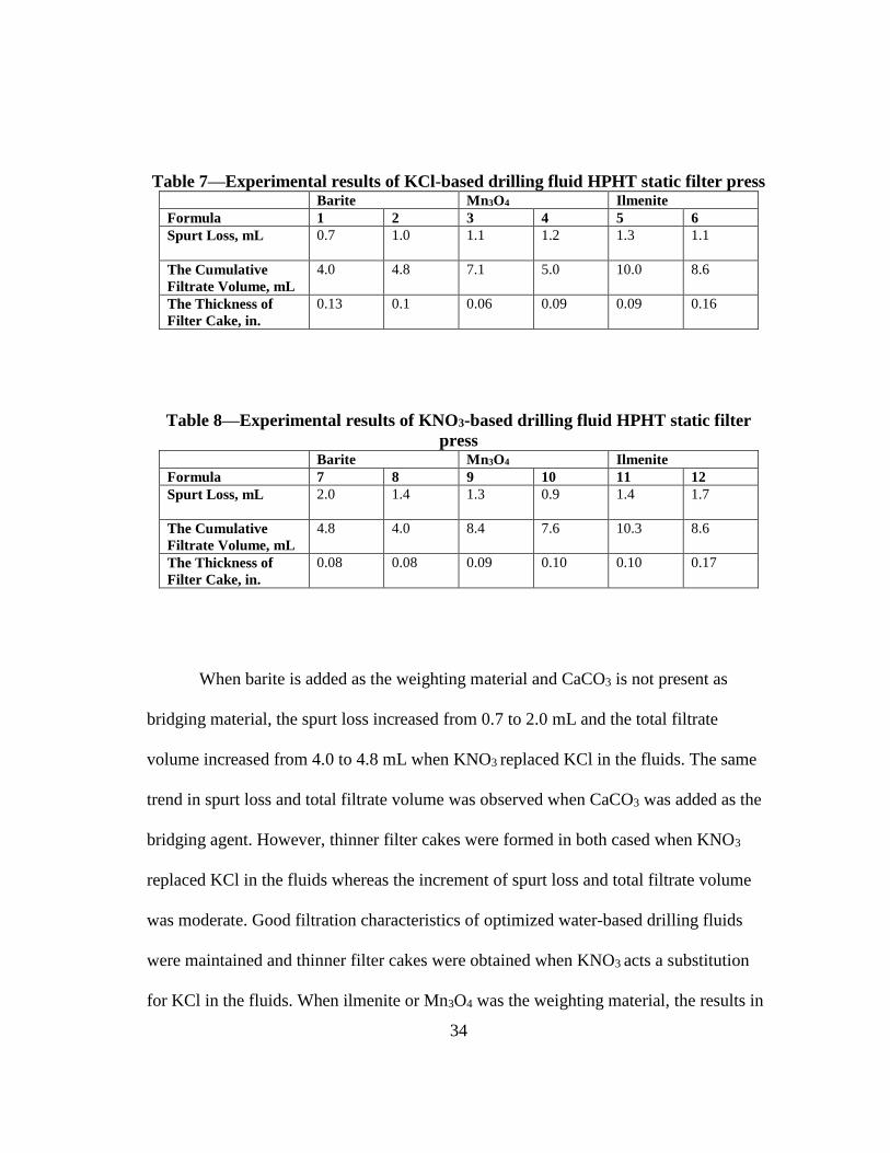
Table 7—Experimental results of KCl-based drilling fluid HPHT static filter press Barite Mn3O4 Ilmenite
Formula 1 2 3 4 5 6
Spurt Loss, mL
0.7 1.0 1.1 1.2 1.3 1.1
The Cumulative
Filtrate Volume, mL
4.0 4.8 7.1 5.0 10.0 8.6
The Thickness of
Filter Cake, in.
0.13 0.1 0.06 0.09 0.09 0.16
Table 8—Experimental results of KNO3-based drilling fluid HPHT static filter
press Barite Mn3O4 Ilmenite
Formula 7 8 9 10 11 12
Spurt Loss, mL
2.0 1.4 1.3 0.9 1.4 1.7
The Cumulative
Filtrate Volume, mL
4.8 4.0 8.4 7.6 10.3 8.6
The Thickness of
Filter Cake, in.
0.08 0.08 0.09 0.10 0.10 0.17
When barite is added as the weighting material and CaCO3 is not present as
bridging material, the spurt loss increased from 0.7 to 2.0 mL and the total filtrate
volume increased from 4.0 to 4.8 mL when KNO3 replaced KCl in the fluids. The same
trend in spurt loss and total filtrate volume was observed when CaCO3 was added as the
bridging agent. However, thinner filter cakes were formed in both cased when KNO3
replaced KCl in the fluids whereas the increment of spurt loss and total filtrate volume
was moderate. Good filtration characteristics of optimized water-based drilling fluids
were maintained and thinner filter cakes were obtained when KNO3 acts a substitution
for KCl in the fluids. When ilmenite or Mn3O4 was the weighting material, the results in

35
Tables 7and 8 show that the spurt loss, the total filtrate volume, and the thickness of
filter cake all slightly increased but were kept at very low values. Good filtration
characteristics and thin filter cake of optimized water-based drilling fluids were achieved
when KNO3 acts a substitution for KCl in the fluids.
Tables 7 and 8 also show the effect of CaCO3 on the filtration characteristics of
the fluids. It is seen that when using barite as the weighting material, the presence of
CaCO3 contributed to slightly higher cumulative filtrate volume. On the contrary, lower
cumulative filtrate volume was obtained when using Mn3O4 and ilmenite as the
weighting material. Photos of the resultant filter cakes from all formulas are provided in
Figures 12 through 23.
Fig. 12—Filter cake of KCl-based drilling fluid using barite as the weighting
material (Formula 1).
Fig. 13—Filter cake of KCl-based drilling fluid using barite as the weighting
material (Formula 2).

36
Fig. 14—Filter cake of KCl-based drilling fluid using Mn3O4 as the weighting
material (Formula 3).
Fig. 15—Filter cake of KCl-based drilling fluid using Mn3O4 as the weighting
material (Formula 4).
Fig. 16—Filter cake of KCl-based drilling fluid using ilmenite as the weighting
material (Formula 5).
Fig. 17—Filter cake of KCl-based fluid using ilmenite as the weighting material
(Formula 6).

37
Fig. 18—Filter cake of KNO3-based drilling fluid using barite as the weighting
material (Formula 7).
Fig. 19—Filter cake of KNO3-based drilling fluid using barite as the weighting
material (Formula 8).
Fig. 20—Filter cake of KNO3-based drilling fluid using Mn3O4 as the weighting
material (Formula 9).

38
Fig. 21—Filter cake of KNO3-based drilling fluid using Mn3O4 as the weighting
material (Formula 10).
Fig. 22—Filter cake of KNO3-based drilling fluid using ilmenite as the weighting
material (Formula 11).
Fig. 23—Filter cake of KNO3-based drilling fluid using ilmenite as the weighting
material (Formula 12).
4.4 CT Images Analysis
Results of filtration tests show use of KNO3 temporary clay stabilizer in the
fluids made comparable or better filter cakes in terms of thickness when compared to

39
filter cakes made by use of KCl. CT scan was conducted to further examine the quality
of the formed filter cake in above tests. In field conditions, thin and impermeable filter
cakes are desirable.
Figures 24-35 show the CT images obtained from the CT scanner. The upper
layer and lower layer correspond, relatively, to filter cake and the limestone core. The
change in color (from green to red) in the upper layer (filter cake) reveals the change of
the density of the filter cake. The radio density refers to a relative inability of X-rays to
pass through the material and is proportional to its density. The combination of the CT
images and HPHT filtration test provides an efficient method to quantify filtration
quality and explain the mechanisms involved (van Overveldt et al. 2012). Table 9 shows
the average CT numbers of the filter cakes for all the tests.
In summary, when barite was the weighting material and CaCO3 as bridging
material was not added, the CT number increased from 7096 to 7844 when KNO3
replaced KCl in the fluids. Previous results show that the thickness of filter cake
decreased from 0.13 to 0.08 in. in the same comparison. Thus, thinner and denser filter
cake was formed in KNO3-based drilling fluid. When CaCO3 was added as the bridging
agent, the same trend was observed but with a higher CT number as the addition of
CaCO3 enhanced the quality of filter cake. In the case of Mn3O4 as the weighting agents,
the CT number decrease a little bit probably because a less dense and slightly thicker
filter cake formed. The same trend as the case of barite was observed when ilmentie was
the weighting material. Filter cake formed from KNO3-based drilling fluid has the
highest density indicated by the highest CT number (its average CT number is 7844)

40
among these drilling fluids that been prepared. When combined with the filtration
results, CT results provides strong evidence that barite is the appropriate weighting
material due to the superiority of its results compared to manganese tetraoxide and
ilmenite.
Fig. 24—CT scanned image for filter cake KCl-based drilling fluid using barite as
the weighting material (Formula 1).

41
Fig. 25—CT scanned image for filter cake KCl-based drilling fluid using barite as
the weighting material (Formula 2).
Fig. 26—CT scanned image for filter cake KCl-based drilling fluid using Mn3O4 as
the weighting material (Formula 3).

42
Fig. 27—CT scanned image for filter cake KCl-based drilling fluid using Mn3O4 as
the weighting material (Formula 4).
Fig. 28—CT scanned image for filter cake KCl-based drilling fluid using ilmenite as
the weighting material (Formula 5).

43
Fig. 29—CT scanned image for filter cake KCl-based drilling fluid using ilmenite as
the weighting material (Formula 6).
Fig. 30—CT scanned image for filter cake KNO3-based drilling fluid using barite as
the weighting material (Formula 7).

44
Fig. 31—CT scanned image for filter cake KNO3-based drilling fluid using barite as
the weighting material (Formula 8).
Fig. 32—CT scanned image for filter cake KNO3-based drilling fluid using Mn3O4
as the weighting material (Formula 9).

45
Fig. 33—CT scanned image for filter cake KNO3-based drilling fluid using Mn3O4
as the weighting material (Formula 10).
Fig. 34—CT scanned image for filter cake KNO3-based drilling fluid using ilmenite
as the weighting material (Formula 11).

46
Fig. 35—CT scanned image for filter cake KNO3-based drilling fluid using ilmenite
as the weighting material (Formula 12).
Table 9—Average CT numbers of filter cakes
Filter Cakes formed from KCl-Based
Drilling Fluid
Filter Cakes formed from KNO3-Based
Drilling Fluid
Formula 1 2 3 4 5 6 7 8 9 10 11 12
CT
Numbers 7096 7795 4553 4624 2756 2895 7844 7914 4153 4455 2826 2989
4.5 Land Farming of KNO3 Drilling Residuals
Land farming is a process in which wastes are incorporated into a soil surface to
degrade, transform, or immobilize the waste constituents by biological, chemical and
physical reactions. Many wells are drilled in agricultural areas, posing concerns to the
public with respect to disposal methods for drilling wastes.

47
Land farming provides a favorable combination of disposal cost, short and long
term liability to the generator, and potential environmental impact. It has the following
benefits: low capital cost and simple technology, multiple applications on same piece of
land, and improved soil characteristics. However, it usually has high maintenance costs
(periodic land tilling, fertilizer use). The soluble salts and cation mobility can affect the
germination and plant growth, and heavy metals uptake by the plants could be passed
along the food chain.
As land farming is an economical technique of drilling waste management, we
can make the nontoxic, safer, and more environmentally residuals by using potassium
nitrate instead of potassium chloride.
However considering the drawbacks of potassium nitrate, such as combustibility,
higher price than potassium chloride, and so on, socioeconomic analyses and technical
experiments are needed.
To evaluate the properties of KNO3 drilling residuals, the following steps should
be ordered in Figure 36 (Wilton et al. 1992):

48
Fig. 36—Steps for land farming of KNO3 drilling residuals.
The conclusion is that downhole wastes, when generated with a properly
formulated drilling fluid, may be land farmed and have no adverse effects on growth
potential when applied at specific loadings.
Drilling waste management practices are subject to all applicable federal and state
regulatory requirements:
The Wyoming Oil and Gas Conservation Commission (WOGCC): Land
farming must be approved by the DEQ (Wyoming Department of
Environmental Quality).
The New Mexico Energy, Minerals and Natural Resources Department:
Disposal method of land farming for drill cuttings and drilling fluids
should meet the new rules. (19.15.2.51 through -55).
The Railroad Commission of Texas (RCC) and the Texas Commission on
Environmental Quality (TCEQ): These institutions provide for various

49
disposal methods that do not require a permit, including the disposal of
certain categories of low-chloride drilling fluid by land farming.
The Utah Department of Environmental Quality (DEQ): Land farming
must be permitted by the Division of Oil, Gas and Mining.
The Florida Department of Environmental Protection (FDEP): No
subsurface formation or zone will be approved for fluid disposal if total
dissolved solids of the formation fluid do not equal or exceed 10,000
parts per million (ppm) and chloride content does not equal or exceed
5,000 ppm.

50
4.6 Potassium Nitrate in a Double Salt Mixture
The optimum concentrations of KCl and KNO3 are 4 and 7 wt% respectively
according to the CST tests. However, the differences between KCl and KNO3 are
relatively small and can be neglected for a concentration of above 4 wt%.
Therefore, KNO3 can be used as the substitute for KCl at concentration of above
4 wt%, functioning comparably to KCl as the temporary clay stabilizer. Potassium
nitrate, as an environmental substitute of KCl, has a higher price than KCl. Considering
this, the optimum double salt mixture which contains KNO3 should be studied to make
the KNO3 more economical as clay stabilizers in drilling and production operations.
To be more economical, an optimum use of potassium nitrate in a double salt
mixture should be found, which will undoubtedly make the potassium safer, more
environmentally friendly, and even more economical. The properties of some potential
double salt mixtures are shown in Table 10:
Table 10—Properties of some potential double salt mixtures. Salt Comments
Calcium Chloride Increase the density of solids-free brines; Provide inhibition of swelling
clays in water phase of invert emulsion drilling fluids.
Calcium Nitrate Nitrate fertilizer.
Calcium Hydroxide Manufactures of additives to oils in petroleum refining industry.
Potassium Sulfate and
Potassium Carbonate Potassium fertilizers, but they are not combustible.
Potassium Formate Potential environmentally deicing salt for use on roads.
Potassium Silicate A corrosion inhibitor.
Magnesium Sulfate,
Magnesium Chloride and
Magnesium Nitrate
Be used widely as fertilizer, but they are not combustible.

51
The properties of double or triple salts can be measured by doing the CST tests.
For the same sample in different fluids, the longer the time of liquid front movement, the
poorer the clay control by the fluid (the greater dispersion). Therefore the optimum
mixture of double or triple salts has the shortest CST time. The CST values of some
double salt mixtures are shown in Figure 37.
The mixture of potassium nitrate and another salt performs better than its
crystallized form of double salt solution. KCl (4 wt%) and a mixed solution of KNO3
and Ca(OH)2 (the molar proportion KNO3 and Ca(OH)2 is 1:1) act similar when treating
3 g bentonite in 100 mL solution as the clay stabilizer. The reason is that the Ca2+ ion
can be exchanged with Na+ (that is usually naturally in the clays before a treatment) or
K+.
The CST time of the 4 wt% mixture solution of the KNO3 and Ca(OH)2 solution
is shorter than 4 wt% KNO3 solution. The reason for this is that in the concentration of 4
wt%, the potassium nitrate is better clay stabilizer in alkaline conditions than in acid or
neutral condition. Further research should be done to determine whether the pH is a
significant factor affecting the swelling control function of clay stabilizers.
K+ double salts should be tested in the future experiments, which means the cations of
both salts are all K+. Only in that way can it be determined whether there are sufficient
amounts of K+ that can treat the clay swelling well, and decrease the cost of KNO3.

52
Fig. 37—The CST values of double salt mixtures (concentration, 4 wt%).

53
5. CONCLUSIONS
Potassium nitrate with the proper K+ concentration matched to the clay’s hydration
characteristics can be used to inhibit the swelling of bentonite in water media as well as
the KCl. KNO3 based drilling fluid is an excellent environmental alternative to KCl-
based drilling fluid and can protect water-sensitive formations and minimize or reduce
clay-related borehole problems. Environmentally friendly drilling fluid using NO3‾ as
plant fertilizer allows drilling wells in the delicate ecological environments.
The following are some highlights of the application:
1. Comparison of twelve formulas of drilling fluids examined show that the KNO3-
based drilling fluid prepared by formula 8 not only has a desirable rheological
properties and appropriate density, but also formed a suitable filter cake
thickness.
2. Considering the formation damage of filter loss, especially to those water-
sensitive reservoirs, and based on cost-equalized concentrations of additive in
water-based drilling fluid, the HPHT filtration test in this study show that barite
is the optimum weighting material to perform potassium-based drilling fluids
system, which can produce one time lower cumulative volume in 30-minute
filtration test than other two weighting materials.
3. When using the barite as the weighting material, although the cumulative filtrate
volume of KCl-based drilling fluids is lower than KNO3-based drilling fluids (in

54
fact, the maximum difference between these two kind of cumulative filtrate
volume is only 0.8 mL), the filter cake thickness formed by the KNO3-based
drilling fluids can be 0.05 in. smaller than the filter cake thickness formed by the
KCl-based drilling fluids after a 30-minute HPHT filtration test.

55
REFERENCES
Akin, S. and Kovscek, A.R. 2003. Computed Tomography in Petroleum Engineering
Research. Geological Society, London, Special Publications 215 (1): 23-38.
http://dx.doi.org/10.1144/GSL.SP.2003.2015.01.03.
Al-Yami, A.S. and Nasr-El-Din, H.A. 2007. An Innovative Manganese Tetroxide/Kcl
Water-Based Drill-in Fluid for HT/HP Wells. Presented at the SPE Annual
Technical Conference and Exhibition, Anaheim, California, 11-14 November.
SPE-110638-MS. http://dx.doi.org/10.2118/110638-MS.
Bakly, O. and Samir, A. 2007. Custom Designed Water-Based Mud Systems Help
Minimize Hole Washouts in High Temperature Wells- Case History from
Western Desert, Egypt. Presented at the SPE/IADC Middle East Drilling and
Technology Conference, Cairo, Egypt, 22-24 October. SPE-108292-MS.
http://dx.doi.org/10.2118/108292-MS.
Brady, M.E., Craster, B., Getliff, J.M. et al. 1998. Highly Inhibitive, Low-Salinity
Glycol Water-Base Drilling Fluid for Shale Drilling in Environmentally Sensitive
Locations. Presented at the SPE International Conference on Health, Safety, and
Environment in Oil and Gas Exploration and Production, Caracas, Venezuela, 7-
10 June. SPE-46618-MS. http://dx.doi.org/10.2118/46618-MS.
Cargnel, R.D. and Luzardo, J.P. 1999. Particle Size Distribution Selection of CaCO3 in
Drill-in Fluids: Theory and Applications. Presented at the Latin American and
Caribbean Petroleum Engineering Conference, Caracas, Venezuela, 21-23 April.
SPE-53937-MS. http://dx.doi.org/10.2118/53937-MS.
Carretero-Carralero, M.D., Farajzadeh, R., Du, D. et al. 2007. Modeling and Ct Scan
Study of Foams for Acid Diversion. Presented at the European Formation
Damage Conference, Scheveningen, The Netherlands, 30 May-1 June. SPE-
107795-MS. http://dx.doi.org/10.2118/107795-MS.
Clark, R.K., Scheuerman, R.F., Rath, H. et al. 1976. Polyacrylamide/Potassium-Chloride
Mud for Drilling Water-Sensitive Shales. Journal of Petroleum Technology 28
(6): 719-727. SPE-5514-PA. http://dx.doi.org/10.2118/5514-PA.
Conway, M.W., Venditto, J.J.J., Reilly, P.B. et al. 2011. An Examination of Clay
Stabilization and Flow Stability in Various North American Gas Shales.
Presented at the SPE Annual Technical Conference and Exhibition, Denver,
Colorado, USA, 30 October-2 November. SPE-147266-MS.
http://dx.doi.org/10.2118/147266-MS.

56
Donham, F. and Young, S. 2009. High Performance Water Based Drilling Fluids
Design. Presented at the Offshore Mediterranean Conference and Exhibition,
Ravenna, Italy, 25-27 March. OMC-2009-111.
Dow, M., Florence, A.S., and Babu, J.V. 2012. Chloride-Free Inhibitive Water-Based
Fluid Significantly Improves Environmental Acceptability for Rain Forest
Locations. Presented at the International Conference on Health, Safety and
Environment in Oil and Gas Exploration and Production, Perth, Australia, 11-13
September. SPE-156824-MS. http://dx.doi.org/10.2118/156824-MS.
Elkatatny, S., Mahmoud, M.A., and Nasr-El-Din, H.A. 2012. Characterization of Filter
Cake Generated by Water-Based Drilling Fluids Using Ct Scan. SPE Drilling &
Completion 27 (2): 282-293. SPE-144098-PA. http://dx.doi.org/10.2118/144098-
PA.
Fann instrument Company. 2015. Filter Press HPHT 500 ML,
http://www.fann.com/fann/products/drilling-fluids-testing/filtration-hpht/fp-hpht-
500ml.page (accessed 8 April 2015).
Grace Instrument Industries LLC. 2014. M3600 VIscometer,
http://www.graceinstrument.com/M3600_Viscometer.shtml (accessed 8 April
2015).
Huadi, F., Aldea, C., MacKereth, B.M. et al. 2010. Successful Kcl Free Highly Inhibitve
and Cost Effective Wbm Applications, Offshore East Kalimantan, Indonesia.
Presented at the IADC/SPE Asia Pacific Drilling Technology Conference and
Exhibition, Ho Chi Minh City, Vietnam, 1-3 November. SPE-132690-MS.
http://dx.doi.org/10.2118/132690-MS.
Khilar, K.C., Vaidya, R.N., and Fogler, H.S. 1990. Colloidally-Induced Fines Release in
Porous Media. Journal of Petroleum Science and Engineering 4 (3): 213-221.
http://dx.doi.org/10.1016/0920-4105(90)90011-Q.
Kjøsnes, I., Løklingholm, G., Saasen, A. et al. 2003. Successful Water Based Drilling
Fluid Design for Optimizing Hole Cleaning and Hole Stability. Presented at the
SPE/IADC Middle East Drilling Technology Conference and Exhibition, Abu
Dhabi, United Arab Emirates, 20-22 October. SPE-85330-MS.
http://dx.doi.org/10.2118/85330-MS.
Miller, R.W., Pesaran, P., and Honarvar, S. 1976. The Effects of Drilling Fluid Mixtures
on Soils and Plant. Presented at the Annual Meeting Papers, Division of
Production, Los Angeles, California, 4-7 April. API-76-F001.

57
Mohan, K.K., Vaidya, R.N., Reed, M.G. et al. 1993. Water Sensitivity of Sandstones
Containing Swelling and Non-Swelling Clays. Colloids and Surfaces A:
Physicochemical and Engineering Aspects 73 (0): 237-254.
Mondshine, T.C. 1973. A New Potassium Based Mud System. Presented at the Fall
Meeting of the Society of Petroleum Engineers of AIME. SPE-4516-MS, Las
Vegas, Nevada, 30 September-3 October. http://dx.doi.org/10.2118/4516-MS.
Novelline, R.A. 2004. Squire's Fundamentals of Radiology. 6th. Harvard University
Press.
O'Brien, D.E. and Chenevert, M.E. 1973. Stabilizing Sensitive Shales with Inhibited,
Potassium-Based Drilling Fluids. Journal of Petroleum Technology 27 (3): 283-
293. SPE-4232-PA. http://dx.doi.org/10.2118/4232-PA.
Olatunde, A.O., Usman, M.A., Olafadehan, O.A. et al. 2012. Improvement of
Rheological Properties of Drilling Fluid Using Locally Based Materials.
Petroleum & Coal 54 (1): 65-75.
OFI Testing Equipment, Inc. 2014. Capillary Suction Timer,
http://www.ofite.com/products/wastewater/product/2117-capillary-suction-timer
(access 8 April 2015).
Pagels, M., Hinkel, J.J., and Willberg, D.M. 2012. Moving Beyond the Capillary Suction
Time Test. Presented at the SPE International Symposium and Exhibition on
Formation Damage Control, Lafayette, Louisiana, USA, 15-17 February. SPE-
151832-MS. http://dx.doi.org/10.2118/151832-MS.
Reid, P.I. and Minton, R.C. 1992. New Water-Based Muds for Tertiary Shale Control.
SPE Drilling Engineering 7 (4): 237-240. SPE-23077-PA.
http://dx.doi.org/10.2118/23077-PA.
Schlemmer, R., Friedheim, J.E., Growcock, F.B. et al. 2003. Chemical Osmosis, Shale,
and Drilling Fluids. SPE Drilling & Completion 18 (4): 318-331. SPE-86912-PA.
http://dx.doi.org/10.2118/86912-PA.
van Oort, E. 1994. A Novel Technique for the Investigation of Drilling Fluid Induced
Borehole Instability in Shales. Presented at the Rock Mechanics in Petroleum
Engineering, Delft, Netherlands, 29-31 August. SPE-28064-MS.
http://dx.doi.org/10.2118/28064-MS.
van Overveldt, A.S., Guo, H., de Blok, G. et al. 2012. A Ct Scan Study of the Leakoff of
Oil-Based Drilling Fluids. Presented at the SPE International Symposium and

58
Exhibition on Formation Damage Control, Lafayette, Louisiana, USA, 15-17
February. SPE-151856-MS. http://dx.doi.org/10.2118/151856-MS.
Wellington, S.L. and Vinegar, H.J. 1987. X-Ray Computerized Tomography. Journal of
Petroleum Technology 39 (8): 885-898. SPE-16983-PA.
http://dx.doi.org/10.2118/16983-PA.
Wilton, B.S., Bloys, J.B., Watts, R.D. et al. 1992. Drilling Wastes Evaluated in Plant
Growth Study. Presented at the SPE Annual Technical Conference and
Exhibition, Houston, Texas, 10-12 February. SPE-24566-MS.
http://dx.doi.org/10.2118/24566-MS.
Zhou, Z.J., Gunter, W.O., and Jonasson, R.G. 1995. Controlling Formation Damage
Using Clay Stabilizers: A Review. Presented at the Annual Technical Meeting,
Calgary, Alberta, 7-9 June. PETSOC-95-71. http://dx.doi.org/10.2118/95-71.