a more flooding-tolerant oxygen electrode in alkaline
TRANSCRIPT
HAL Id: hal-00552351https://hal.archives-ouvertes.fr/hal-00552351
Submitted on 6 Jan 2011
HAL is a multi-disciplinary open accessarchive for the deposit and dissemination of sci-entific research documents, whether they are pub-lished or not. The documents may come fromteaching and research institutions in France orabroad, or from public or private research centers.
L’archive ouverte pluridisciplinaire HAL, estdestinée au dépôt et à la diffusion de documentsscientifiques de niveau recherche, publiés ou non,émanant des établissements d’enseignement et derecherche français ou étrangers, des laboratoirespublics ou privés.
A More Flooding-Tolerant Oxygen Electrode in AlkalineElectrolyte
M. B. Ji, Zidong Wei, S. G. Chen, Q Zhang, Y.Q. Wang, X. Q. Qi, L. Li
To cite this version:M. B. Ji, Zidong Wei, S. G. Chen, Q Zhang, Y.Q. Wang, et al.. A More Flooding-TolerantOxygen Electrode in Alkaline Electrolyte. Fuel Cells, Wiley-VCH Verlag, 2010, 10 (2), pp.289.�10.1002/fuce.200800150�. �hal-00552351�

For Peer Review
A More Flooding-Tolerant Oxygen Electrode in Alkaline
Electrolyte
Journal: Fuel Cells
Manuscript ID: FUCE.200800150.R3
Wiley - Manuscript type: Original Research Paper
Date Submitted by the Author:
13-Dec-2009
Complete List of Authors: JI, M. B. WEI, Zidong; Chongqing Univ., Chemistry CHEN, S. G. ZHANG, Q Wang, Y.Q.
QI, X. Q. LI, L.
Keywords: AIR ELECTRODE, Alkaline Fuel Cell, FLOODING, METAL/AIR BATTERY, WATER MANEGEMENT
Wiley-VCH
Fuel Cells
For Peer Review
1
A More Flooding-Tolerant Oxygen Electrode in Alkaline
Electrolyte
M. B. Ji1,2, Z. D. Wei*1,2, S. G. Chen2, Q. Zhang1,2, Y. Q. Wang2, X. Q. Qi1,2, L. Li1,3
1State Key Laboratory of Power Transmission Equipment & System Security and New Technology, School of
Chemistry and Chemical Engineering, Chongqing University, Chongqing, 400044; China
2School of Material Science and Engineering, Chongqing University, Chongqing, 400044; China
*Corresponding author’s E-mail: [email protected] (Wei), Tel: +86 23 60891548, Fax: +86 23 65106253.
Abstract
Owing to the inherent performance and cost advantages alkaline fuel cells (AFC) have been being a highlight in
fuel cells research. However the degradation of the performance coming from the cathode due to the oxygen
diffusion limit leaded by the flooding is a critical issue to overcome. The objective of this study is thus devoted
to mitigate the water flooding happening in the pores of a porous oxygen electrode by using a more
flooding-tolerant electrode (FTE) which contains water-proof oil, dimethyl-silicon-oil (DMS). The FTE
performance was checked in two cases, the whole FTE completely immersed in 1 mol L-1 KOH, and its catalyst
layer side exposed to 1 mol L-1 KOH but its back side to gas chamber, in order to simulate the situation of
electrode flooded and electrode at normal operation condition, respectively. The results indicate that the FTE
displays outstanding flooding-tolerant capability, especially in the case of a large current density, in which mass
transport of gas reactant is in a dominant position.
Key Words: flooding-tolerant, AFC, metal/air batteries, water flooding, water-proof oil
1. Introduction
Page 1 of 39
Wiley-VCH
Fuel Cells
123456789101112131415161718192021222324252627282930313233343536373839404142434445464748495051525354555657585960
For Peer Review
2
Fuel cells allow an environmentally friendly and highly efficiently conversion of
chemical energy to electricity. Therefore, they have a high potential to become important
components of an energy-efficient and sustainable economy. The main challenges in the
development of fuel cells are cost reduction and long-term durability [1]. In recent years,
there has been the reemergence of interest in alkaline fuel cells (AFCs), as the development
of low cost polymer electrolyte membrane fuel cells (PEMFCs) took much more efforts than
expected [2,3]. Whereas the cost can be significantly reduced by the use of non-noble and
less costly catalysts [3-5] for the faster oxygen reduction kinetics in liquid alkaline
electrolyte over acidic media, the poor lifetime, mainly due to the hydrophobic area of the
gas diffusion electrode flooded by water and electrolyte, desiderates to be overcome, which
has become the decisive factor for their commercialization [6]. In practical applications, not
more than 5000 operating hours [3] could be obtained. It is obvious that most efforts of any
research group dealing with AFCs is not to decrease the cost as the cost is low compared to
other fuel cell systems anyway, but to increase the lifetime [2], especially for the oxygen
electrode ( i.e. the cathode of AFCs and metal/air batteries).
Gas diffusion oxygen electrodes, where molecular oxygen is reduced, are vital to AFCs
and metal/air batteries performance. As shown in Figure 1, the oxygen reduction reaction
(ORR) takes place in the three-phase zone formed by the catalyst, the electrolyte and
reactants. For the transport of the oxygen to the three-phase zone in the electrodes and the
transport of OH- ions out of the electrodes a porous structure is needed, whereby a
hydrophilic pore system is required for the transport of water with hydroxide group and a
hydrophobic pore system for the transport of the oxygen or air. Therefore, the balance of
Page 2 of 39
Wiley-VCH
Fuel Cells
123456789101112131415161718192021222324252627282930313233343536373839404142434445464748495051525354555657585960

For Peer Review
3
hydrophobic and hydrophilic properties of the materials determines the operation conditions
and the electrochemical performance. For the stability of the output performance, it is
necessary that hydrophobicity does not change during the fuel cell operation. Generally,
polytetrafluoroethylene (PTFE) is used to provide a hydrophobic character to the electrodes
and the hydropobicity of the electrodes is adjusted by the concentration of the PTFE [7, 8]. In
principle, PTFE is not only strongly hydrophobic, but it has a very high stability in
aggressive chemical environmental conditions. However there are many investigations have
observed the decomposition [1,3,6,7,9,10] and partial removal [7,11,12] of PTFE during both
the AFCs and metal/air batteries operation, which reduces the hydrophobic property and
results in the excessive oxygen electrode wettability. As a result, the built up of liquid
electrolyte in the gas pores prevents the efficient diffusion of oxygen to the reactive sites and
also reduces the effective area of the three-phase gas–solid–liquid interface, thereby leading
to the final flooding of the oxygen electrode [13] as shown in Figure 1.
Moreover, as the current demand increases during operation, it is believed that the
reaction front moves outward toward the air side of the electrode, and more of the electrode
surface area participates in the reaction. The liquid electrolyte would film over or flood the
electrode surface, thereby blocking oxygen access and reducing the active (available)
three-phase interfacial area for reaction [14]. Besides, the imperfections in the wet proofing
coating in which the pressure of the static KOH (5-10 kPa over ambient) forces the KOH into
the dry pores can lead to a slow and constant physical flooding phenomenon [3].
Indeed the negative impact of carbon dioxide on the porous structure of the oxygen
electrode is also an unavoidable factor if the system uses air as the oxidant instead of pure
Page 3 of 39
Wiley-VCH
Fuel Cells
123456789101112131415161718192021222324252627282930313233343536373839404142434445464748495051525354555657585960
For Peer Review
4
oxygen. As the result of poisoning reaction of carbon dioxide and alkaline electrolyte the
formation of carbonate may precipitate and block the micro pores and thus limit the gas
diffusion inside the catalytic layer to the active sites. The phenomenon will be more serious
at lower temperature [15] and in higher concentration electrolyte [3, 16]. Thus the carbonate
precipitation in the porous system significantly enhances the ‘‘flooding’’ of the gas electrode
and interferes with the electrode kinetics, affects the durability and activity of gas diffusion
electrodes.
The most common method to alleviate the negative influence of carbon dioxide is the
use of chemical scrubbers, (i.e. soda lime [2, 3, 17-21]) or regenerative scrubbers, which
function on the principles of pressure-swing adsorption, temperature-swing-absorption, and
the steam-regeneration of amines [3] for scrubbing CO2 from the air-stream. But this is
cumbersome and comparatively costly not a strong option for commercial systems [21].
The net result of all cathode flooding phenomena is that the supply of oxidant to the
system lags behind the demand causing a shortage of oxygen and possible local starvation of
oxygen for the reaction thus increasing the concentration overpotential of the cathode. Worse
still, the oxygen electrode cannot sustain the current density from the stack, resulting in
premature battery failure and the final cell reversal [2]. As long as the cell reversal appears,
the output and mechanical damage of the stack and the electrode will be seriously impaired.
In order to make the oxygen electrode more resilient to the effect of flooding, the current
methods include improving the waterproofing of the electrode via the use of more
hydrophobic carbons [13], binary carbon supports [22, 23], more PTFE [24-26], and
appropriate heat treatments of the finished electrodes [3]. However, higher PTFE loading
Page 4 of 39
Wiley-VCH
Fuel Cells
123456789101112131415161718192021222324252627282930313233343536373839404142434445464748495051525354555657585960
For Peer Review
5
increases the resistance and decreases the performance of the cell [27], besides the denaturing
of the PTFE binder with time is an irreversible degradation process. Moreover, the reduction
of the electrode surface area and the increase in the wetting of the electrode is also a function
of hours the electrode is operated [28].
So it very important to design a gas diffusion oxygen electrode with stabile three phase
interface that electrolyte can penetrate into but not over-flood. The objective of this study is
thus devoted to mitigate the flooding problem with the development of a novel oxygen
electrode containing water-proof oil, dimethyl-silicon-oil (DMS), which was added into parts
of cathode pores of the conventional MnO2/C electrode. The solubility of oxygen in DMS is
over 10 times higher than that in water. Thus, the pores occupied by DMS form permanent
channels for oxygen transportation, in which the DMS is not easily extruded by water, no
matter whether the cathode is flooded or not. The channels for oxygen transportation and
OH- ions are orderly allotted between the channels/pores occupied by DMS and electrolyte,
respectively, with the addition of the water-proof oil DMS as shown in Figure 1, where the
oxygen and OH- hold their own fixed and stabile transport channels, respectively. Because
carbonate precipitation only happens in the alkaline aqueous phase rather than in the
water-proof oil phase, we suppose that the addition of DMS may alleviate the electrolyte
carbonation. The electrode containing such water-proof oil is called flooding-tolerant
electrode (FTE) hereafter. The electrode without such water-proof oil is named a
conventional MnO2/C electrode (CME) for the sake of contrast.
2. Experimental
Page 5 of 39
Wiley-VCH
Fuel Cells
123456789101112131415161718192021222324252627282930313233343536373839404142434445464748495051525354555657585960
For Peer Review
6
2.1 Preparation of the FTE
The catalyst 7 wt.% MnO2/C was obtained by calcining the mixture of SL-30 carbon
black (Zigong carbon black, China), Mn(NO3)2 at 340 °C for 0.5 h according to the method
reported in Reference [29]. Conventional MnO2/C electrode (CME) was composed of a gas
diffusion layer and a catalyst layer. The gas diffusion layer was prepared on wet-proofed
carbon paper as described in Reference [12]. In short, The carbon powder (Vulcan XC-72,
Cabot Corp.), 30 wt.% of PTFE and ethanol was ultrasonically mixed with a ratio 13:7 of
carbon to solid PTFE loading. The viscous mixture was coated onto the wet-proofed carbon
paper (Toray Co, Jap.) with PTFE and then heated at 340 °C for 30 minutes to prepare the
micro-porous layer (MPL). The thickness of the carbon paper and the MPL is 260 µm and
20µm, respectively. The PTFE content in carbon paper is 40 wt.% and the loading of the
carbon in MPL is 1 mg cm-2. A suspension consisting of catalysts 7 wt.% MnO2/C, 30 wt.%
of PTFE and/or 0.5 wt.% Nafion solution (Du Pont) and ethanol was first ultrasonically
mixed for about 15 min, respectively. The weight ratios of MnO2/C to solid PTFE or Nafion
were maintained at both 17:3. The suspension was pipetted onto the gas diffusion layer and
finally heated at 340 °C and/or 145 °C, respectively. Thus the PTFE-bonded CME and
Nafion-bonded CME were obtained; the latter was used to simulate the completely
hydrophilic CME after decomposition or partial removal of PTFE. The MnO2 loading was
0.5 mg cm-2 for all electrodes and the thickness of the catalyst layer was ca. 170 µm by
estimation.
The FTE was obtained based upon the CME according to the following steps. First, the
50 vol.% DMS solution with iso-propanol as solvent was sprayed onto the catalyst side of the
Page 6 of 39
Wiley-VCH
Fuel Cells
123456789101112131415161718192021222324252627282930313233343536373839404142434445464748495051525354555657585960
For Peer Review
7
above CME, and then extracted with a water pump from the opposite of the electrode to
make DMS pass through the porous electrode and remove the surplus DMS under a pressure
of 10 kPa. And finally, the electrode with some residues of DMS was heated at 120 °C for 5
minutes to remove the solvent used for diluting DMS. The DMS loading was calculated by
weighing the mass difference of the CME before and after the DMS treatment. The DMS
containing CME is the FTE. The loading of the DMS is 2.5 mg cm-2 for all FTE discussed in
this work.
2.2 Electrochemical characterization
A FTE or CME together with an Hg/HgO reference electrode and a Pt wire counter
electrode were completely immersed in 1mol L-1 KOH to simulate the situation of an
electrode flooding. In this “completely immersed” case, the whole electrode was dipped in
the electrolyte solution, i.e., the two sides, catalyst layer side and back side of the electrode,
were covered by electrolyte. The active area of the immersed electrodes is 1.5 cm2. Pure
oxygen was bubbled into the electrolyte solution near the back of the electrodes during the
test. Even so, the FTE electrode is only considered in partial flooding situation owing to
some oxygen bubbles impinged on the cathode getting O2 gas directly into some of the more
hydrophobic pores in the electrode. The results are shown in Figures 3, 4 and 5. The
performance of the FTE was tested using an Autolab PGSYAT302 instrument (IECO
CHEMIE B.V., The Netherlands) with General Purpose Electrochemical System (GPES) and
frequency response analysis software (FRA).
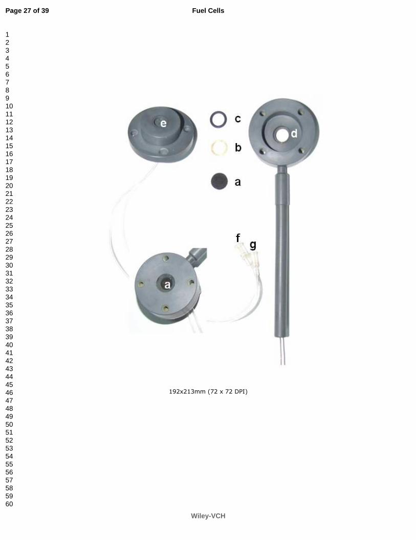
A half cell as shown in Figure 2 was employed to simulate AFCs in a real operation
Page 7 of 39
Wiley-VCH
Fuel Cells
123456789101112131415161718192021222324252627282930313233343536373839404142434445464748495051525354555657585960
For Peer Review
8
situation in which the FTE or CME is served as an oxygen cathode. In this case, only the
catalyst layer side was exposed to 1 mol L-1 KOH but its back side to gas chamber. The
results are shown in Figures 6 to 13, among which Figures 9 and 10 are the results based on
the self-breathing air cathode, i.e., no force was used to drive air or oxygen flow into the
cathode. In the case of Figures 6, 7, 8, 11, 12 and 13 oxygen was fed at rate of at 60 mL min-1
by pump. In this “half immersed” case, the catalyst layer side with 1.0 cm2 active area
exposed to KOH solution while the back side of the air electrode exposed to a gas chamber
connected to oxygen source fed with ambient pressure, i.e., 101.3 kPa.
All electrochemical measurements were conducted at 25 °C. Hg/HgO electrode was
employed as reference electrode in measurement. However, all potentials given in this paper
have been transferred to ones vs. the RHE according to the relationship of E (RHE) = E
(Hg/HgO) + 0.926 V [30].
2.3 Porosity change with introduction of DMS
The change in internal structure of the CME before and after introduction of DMS was
assessed using a N2 adsorption specific surface area analyzer (ASAP2010, Micromeritics
Instrument Corp., USA).
3. Criteria for selection of water-proof oil
Water-proof oil if used successfully in an AFC or metal/air battery system must meet the
following requirements:
(1) Chemically inert and thermally stable;
(2) Non-polarity molecule structure. According to the principle "Like dissolves like",
Page 8 of 39
Wiley-VCH
Fuel Cells
123456789101112131415161718192021222324252627282930313233343536373839404142434445464748495051525354555657585960
For Peer Review
9
oxygen will dissolve better in a non-polar solvent than in a polar solvent;
(3) Freezing point being as low as possible but flash point as high as possible, which
should cover all temperature of AFC and metal/air batteries operation;
(4) A low vapor pressure over a large temperature scope to guarantee high oxygen
solubility at any temperature, low or high;
(5) Low viscosity required for efficient diffusion of dissolved oxygen;
(6) Small surface tension that is helpful for the oil itself to permeate into the deep pores
in a porous electrode.
There is contradiction among the above criteria, for example, macromolecule with a
small molecular weight usually has a low freezing point and low viscosity but not high flash
point or low vapor pressure or large surface tension , and vice versa. With hard compromise,
dimethyl-silicon-oil (DMS) with mole molecular weight of 2000 g mol-1 comes into sight,
which is a kind of transparent liquid with colorless, flavorless and nontoxic property. Its
viscosity is as low as 15 mPa·s (25 °C). The concentration of dissolved oxygen in DMS is
0.168~0.190 ml.ml-1 (101.3 kPa, 25 °C) [31], which is 10 times higher than that in 1 mol L-1
KOH (0.0184 ml.ml-1) (101.3 kPa, 25 °C) [32]. Moreover, according to Henry’ law, the O2
partial pressure at a constant total pressure decreases significantly with increase of
temperature and water vapor partial pressure, thus, the concentration of dissolved oxygen in
water, which is directly proportional to the O2 partial pressure in gas phase, will decreases to
0.0067 ml.ml-1 at 80 °C [32]. While DMS vapor pressure keeps as small as ~10-6 k Pa in a
temperature range of 0 ~ 100 °C, thus, the concentration of dissolved oxygen in DMS almost
maintains unchanged in a temperature range of AFC and metal/air batteries operation. Thus,
Page 9 of 39
Wiley-VCH
Fuel Cells
123456789101112131415161718192021222324252627282930313233343536373839404142434445464748495051525354555657585960
For Peer Review
10
the concentration of dissolved oxygen in DMS will be 30 times higher than in 1 mol L-1
KOH at 80 °C. The relatively low freezing point (-80 °C) and quite high flash point (195 °C)
of DMS are also very favorable to AFC and metal/air batteries operation. The surface tension
of DMS (~19 mN m-1) is approximately 1/3 of that of water (~66 mN m-1). It means that
DMS has much better penetrability into the deeper pores than water and can bring the
dissolved oxygen into the deeper pores in a porous electrode, which extends the liquid/solid
interface more effective for the ORR. The loss in O2 diffusion coefficient with substitution of
DMS for water due to increase in viscosity from 1 of water to 15 mPa·s of DMS can be
estimated according Wilke-Chang’s equation [33]
( )6.0
2180 104.7
bAB
BAB
V
TMD
µ
φ−×= (1)
Where 0ABD is diffusion coefficient of solute A in solvent B. MB and µB are mole molecular
weight and viscosity (mPa·s) of solvent B, respectively. T is absolute temperature (K). VbA is
mole volume of solute A (for O2: 25.6 cm3 g-1 mol-1) at normal boiling point. φ is a factor
associated with solvent B, which is 2.6 for water and 1 for DMS. Thus, the diffusion
coefficient of oxygen is 2.1×10⁻⁵ cm2 s-1 in water and 1.0×10⁻⁵ cm2 s-1 in DMS at 298 K. This
computed result indicates that there is a half sacrifice in oxygen diffusion coefficient for
DMS compared to that in liquid water. When the catalyst layer is severely flooded, according
to the flooded agglomerates model [34], the oxygen diffusion limiting current density il is
directly proportional to the dissolved oxygen concentration cl
OC2 in water or DMS [35-37]:
il = (nFcl
OC2Dcl)/L (2)
Where Dcl is the oxygen diffusion coefficient in solution of the catalyst layer; L is the
Page 10 of 39
Wiley-VCH
Fuel Cells
123456789101112131415161718192021222324252627282930313233343536373839404142434445464748495051525354555657585960
For Peer Review
11
thickness of the catalyst layer; the dissolved oxygen concentration cl
OC2
and diffusion
coefficient Dcl are 8.43 ×10⁻⁷ mol cm-3 and 1.43×10⁻⁵ cm2 s-1 in 1 mol L-1 KOH solution [36]
and 7.77 ×10⁻⁶ mol cm-3 and 1.0×10⁻⁵ cm2 s-1 in DMS [31] at 25 °C and 101.3 kPa,
respectively. Thus, based upon the above numbers the calculated oxygen diffusion limiting
current densities vs the effective diffusion thickness L in liquid phase of the catalyst layer
(170 µm) are listed in the Table 1. The effective diffusion coefficient is corrected by
multiplying void-volume fraction, generally, 50 % for the catalyst layer. From Table 1,
regardless the effective diffusion thickness L in liquid phase of the catalyst layer, we get at
least 6.6 times higher oxygen diffusion limiting current densities with substitution of DMS
for KOH solution at 25 °C. Such an increase in limiting current densities will be further
strengthened at a temperature greater than 25 °C due to the decrease of dissolved oxygen
concentration in higher temperature KOH solution. For example, at 80 °C and 101.3 kPa, the
dissolved oxygen concentration cl
OC2 is only 3.0 × 10⁻⁷ mol cm-3 in 1 mol L-1 KOH solution
[32], but in DMS maintains nearly 7.77 ×10⁻⁶ mol cm-3 as same as that at 25 °C. Thus, in the
case of 80 °C operation temperature, the oxygen diffusion limiting current density will be
enhanced to at least 18 times with substitution of DMS for KOH solution. Furthermore, the
AFC is mostly operated at 80 °C. Therefore, the novel FTE with DMS will play a significant
role for an AFC in application. The effective diffusion thickness L in the liquid phase of the
catalyst layer estimated according to the data disclosed in Figures 3 to 10 is in a range of 1
~2 µm. It means the electrodes discussed in this work are only partially flooded by
electrolyte even though they were completely immersed into the electrolyte as compared with
the total thickness 170 µm of the catalyst layer. As a matter of fact, we can not completely
Page 11 of 39
Wiley-VCH
Fuel Cells
123456789101112131415161718192021222324252627282930313233343536373839404142434445464748495051525354555657585960
For Peer Review
12
impede some O2 gas directly getting into some of the more hydrophobic pores owing to some
oxygen bubbles impinging on the cathode. The severe flooding situation may be achieved by
using more hydrophilic material as the bonder of the FTE and CME. In this case, it’s more
easily for KOH electrolyte to fill in the more hydrophilic pores. Thus, the real diffusion
thickness for those pores that are completely flooded is much longer than the mean effective
diffusion thickness 1 ~2 µm as estimated above because we cannot deduct the mass transport
contribution through hydrophobic pores that are not flooded at all.
4. Results and discussion
4.1 Performance of the FTE and CME in a severe water-flooding situation
An experiment in which the both faces of the electrodes FTE and CME were entirely
immersed in O2-saturated KOH was designed to simulate severe flooding of oxygen
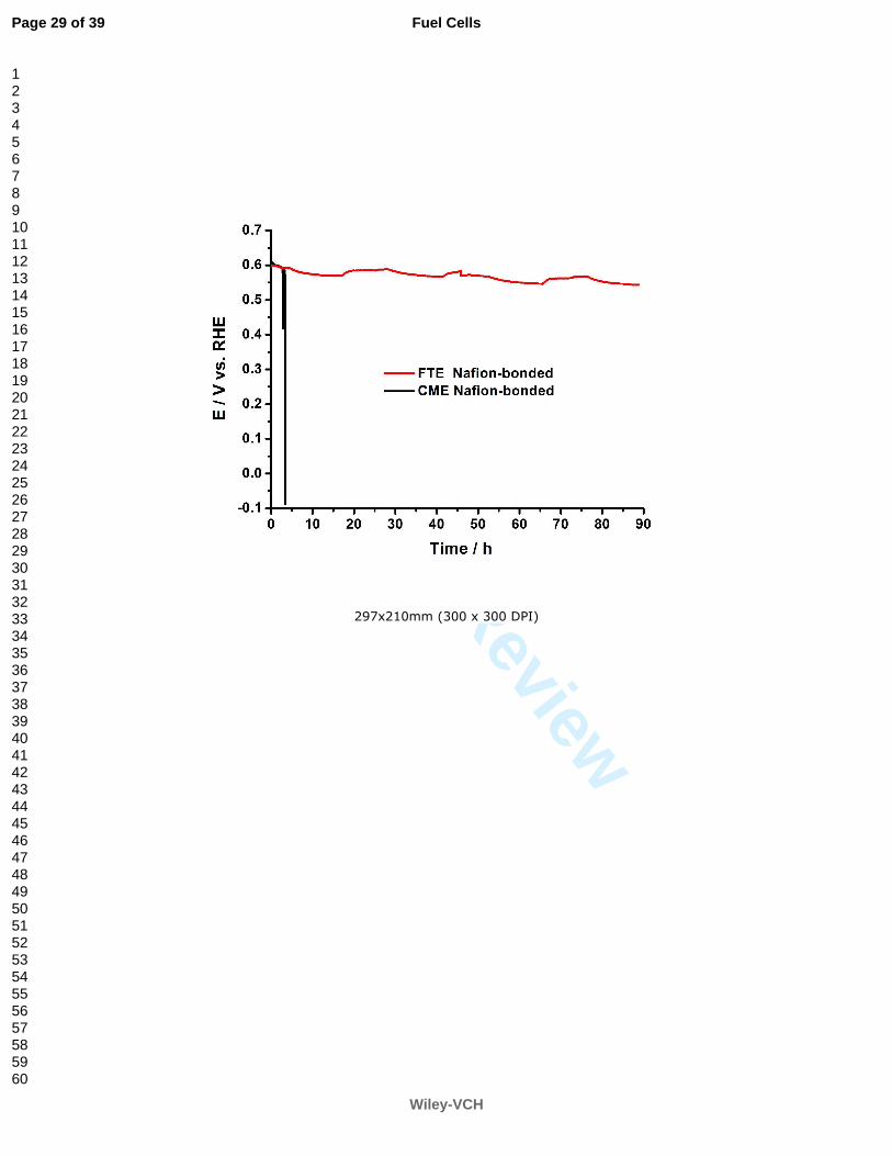
electrodes, Figures 3 and 4 record chronopotentiometry of electrodes FTE and CME as
dipped in 1 mol L-1 KOH, in which a gradually increased cathode current (Figure 3) and a
constant cathode current (Figure 4) were imposed on the electrodes, respectively. Figure 5
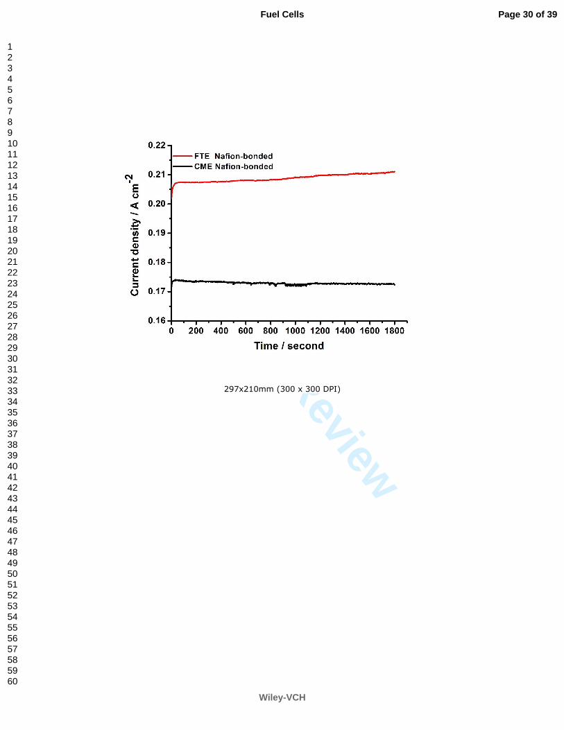
records chronoamperometry of electrodes FTE and CME completely dipped in 1 mol L-1
KOH. Oxygen was fed at 10 mL min-1 near the back of the electrodes during the whole
measurement.
With current flow through the electrode/electrolyte interface, the electrode potential will
depart from the balance value. Electrode potential is going to shift toward the negative
direction for cathode polarization and toward the positive direction for anode polarization.
Figures 3, 4 and 5 tell us that, the FTE can sustain a larger polarization current (Figures 3 and
Page 12 of 39
Wiley-VCH
Fuel Cells
123456789101112131415161718192021222324252627282930313233343536373839404142434445464748495051525354555657585960
For Peer Review
13
5) and a longer time at a fixed polarization current (Figure 4) than the CME can. It suggests
that the DMS in the FTE can provide channels with higher O2 transport through the liquid oil
than through liquid water, and thus more O2 is brought into the catalyst surface through the
liquid oil than through liquid water. Figure 4 tells that the CME cannot sustain longer than 3
hours at polarization current density of 60 mA cm-2 before the electrode potential drops to
-0.1 V. However, the FTE can sustain nearly 90 hours without obvious deterioration in
electrode potential. The marked drop in electrode potential is a symbol of O2 depletion in the
electrode. With oxygen starvation, the cell reversal will soon appear in succession. Generally,
at too high current densities, the electrode is going to be under mass transfer control,
meaning that mass transport becomes the rate-determining step. The better flooding-tolerant
capability of the FTE than the CME as they are completely dipped in KOH electrolyte is no
doubt contributed to that for the FTE some of its channels filled by the liquid oil have higher
O2 transport but for the CME some of its channels filled by the liquid water have lower O2
transport.
4.2 Half-cell tests
An experiment that can simulate the situation of a real half-cell in AFC and metal/air
batteries is necessary for assessing electrode performance. There are two types of oxygen
electrodes. One is made from PTFE-bonded catalysts, and the other from Nafion-bonded
catalysts. The later was especially used to simulate a complete hydrophilic CME as reported
after decomposition and partial removal of PTFE [1, 3, 6, 7, 9-12]. Poor mass transport of
oxygen, which can be caused by low electrode porosity or by excessive wetting of the
electrode, significantly increases polarization and reduces operating voltage. Generally, as
Page 13 of 39
Wiley-VCH
Fuel Cells
123456789101112131415161718192021222324252627282930313233343536373839404142434445464748495051525354555657585960

For Peer Review
14
the current demand increases during operation, it is believed that the reaction front moves
outward toward the air side of the electrode, and more of the electrode surface area
participates in the reaction. The liquid electrolyte can film over or flood the electrode surface,
thereby blocking oxygen access and reducing the available three-phase interfacial area for
reaction. Therefore, compared with the CME, because the DMS in the FTE can supply the
channels with higher O2 transport through the liquid oil than through liquid water in the CME,
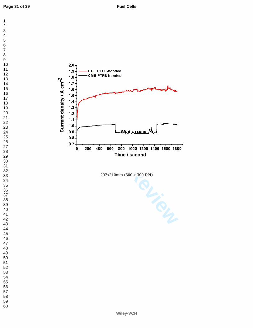
the half-cell consisting of FTE cathode outputs higher cathode current density at a certain
potential (Figure 6) or higher cathode potential (Figure 7) at a certain current density than the
half-cell consisting of CME. Figure 6 indicates that the half-cell with CME cathode could
output 1 A cm-2 current but the half-cell with FTE cathode as large as 1.5 A cm-2 as the
half-cell potential jumps from 1.126 to 0.326 V. To fully demonstrate the flooding-tolerant
capability of the FTE, we intentionally made the half-cell operate at a larger current density.
In this case, the half-cell will suffer from the serious oxygen starvation and oxygen transport
troubles. Of course, this will make the half-cells potential go down. Besides, the O2 reduction
reaction (ORR) on MnO2 electro-catalysts undergoes a two-electron process to produce HO2-
[38-42], thus, the use of low-cost MnO2 electro-catalysts means a partial sacrifice of cathode
potential relative to the direct four-electron process of ORR on noble metal of Pt [42]. Thus
1.5 A cm-2 and 1.0 A cm-2 of the current output for the half-cell with FTE or with CME is a
quite large number in consideration of poor catalysis of MnO2. Figure 7 discloses that with
the gradual increase of cathode current, the cathode potential decline of the half-cell with
FTE is not as steep as that of the cell with CME. At an acceptable current output, for example
0.4 A cm-2, the electrode potential is 0.6 V for the half-cell with FTE but 0.47 V for CME.
Page 14 of 39
Wiley-VCH
Fuel Cells
123456789101112131415161718192021222324252627282930313233343536373839404142434445464748495051525354555657585960

For Peer Review
15
Such an increase over 100 mV in voltage output of the half-cell is naturally assigned to the
channels with higher O2 transport through the liquid oil than through liquid water in
company with DMS substituting for water.
In Figure 7, a gradually increased cathode current was imposed on the electrode with a
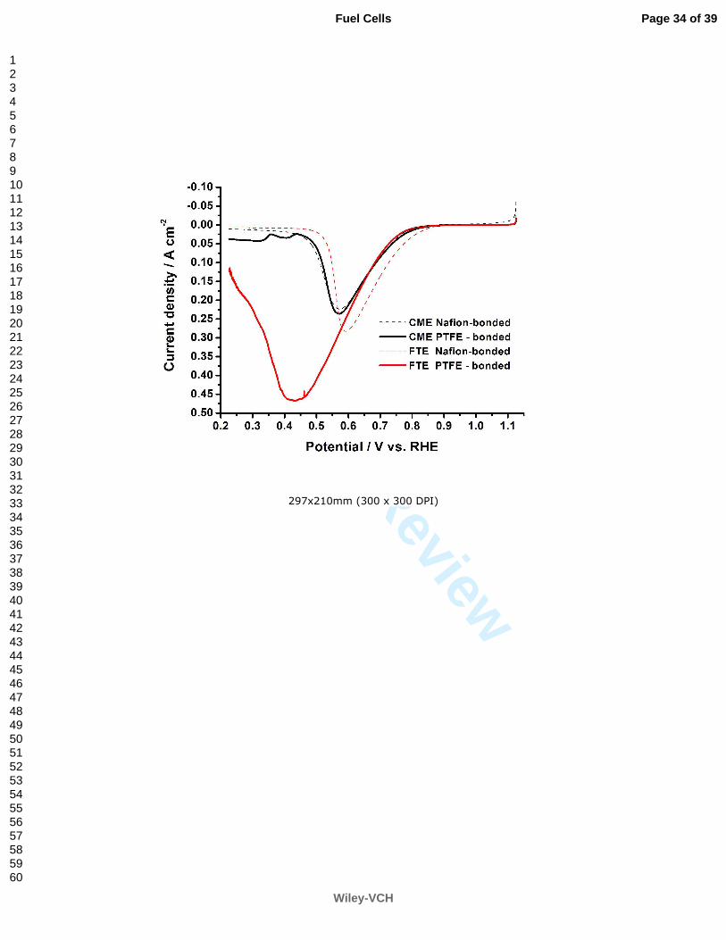
time interval of 120 s. On the contrary, the polarization curves in Figure 8 are obtained by
potentiodynamic scan with a scan rate of 2 mV s-1. Therefore, it takes 20 min for the former
but less than 10 min for the latter to finish the whole test. The flooding is getting more severe
as an electrode is maintained at a larger current density for a long length of time [28]. That is
why the performance of PTFE-bonded cathode, CME or FTE, seems not as good in Figure 7
as in Figure 8.
In addition, the differences in current density between the “PTFE-bonded CME”
electrode and the “PTFE-bonded FTE” electrode shown in Figure 8 at a high cathode
potential, for instance, 0.7 V, is not as great as that at low cathode potential, for instance, 0.3
V. It means that the performance improvement of the half-cell with FTE at small polarization
is not as noticeable as at large polarization. The large polarization means the large current
density and lower cathode potential. In this case mass transport is dominant over other
processes. Thus, the half-cell with good mass transport cathode, such as FTE, will
accordingly exhibit a better performance. However, at small polarization, the
rate-determining step may be the electron transport step rather than the mass transfer step.
Thus the measurement used for improving the mass transport would not improve the whole
performance of the electrode.
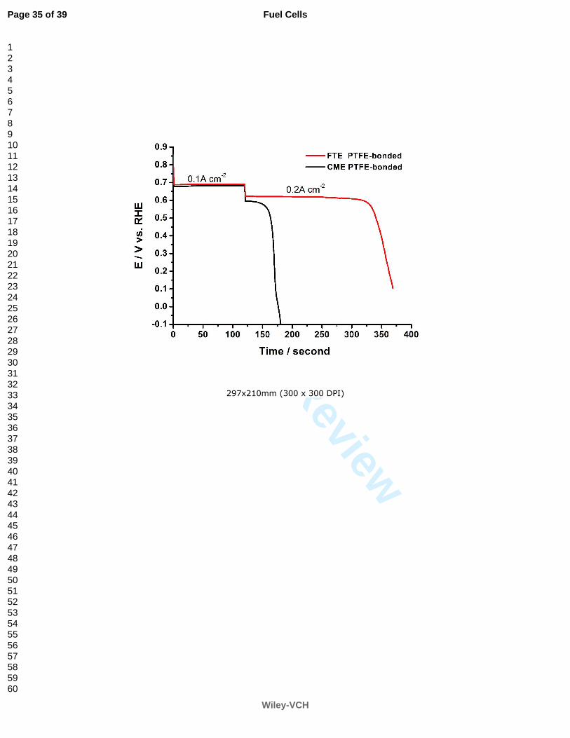
Figures 9 and 10 are results based on the self-breathing cathodes. O2 was fed at 60 mL
Page 15 of 39
Wiley-VCH
Fuel Cells
123456789101112131415161718192021222324252627282930313233343536373839404142434445464748495051525354555657585960
For Peer Review
16
min-1 via the gas chamber as shown in Figure 2 before measurement and then stopped after
measurement. The oxygen needed during experiment comes from (1) the oxygen stored in
the pores of FTE and CME, and (2) air through the self-breathing of the cathode side exposed
to the air. Figures 9 and 10 tell that more O2 was stored in the FTE than the CME. The
half-cell with FTE can sustain a larger polarization current (Figure 9) and longer time at a
fixed polarization potential (Figure 10) than the CME in 1 mol L-1 KOH. It is worth noting
that in comparison with the Nafion-bonded FTE, the PTFE-bonded FTE demonstrated much
better catalysis to the ORR as shown in Figure 9. It is owing to the difference in
hydrophobicity between PTFE and Nafion. The former is more hydrophobic but the latter
less. The DMS is also hydrophobic. Thus, the pores in a PTFE-bonded FTE are more suitable
for DMS storage than those of a Nafion-bonded FTE. Therefore there are more channels
filled by the DMS in the PTFE-bonded FTE than in the Nafion-bonded FTE. In addition,
Nafion-bonded FTE should be more easily subject to electrolyte penetration than the
PTFE-bonded FTE. Therefore, more pores in Nafion-bonded FTE would be filled by KOH
than in PTFE-bonded FTE. Thus, the PTFE-bonded FTE air electrode will own more oxygen
transport channels and higher O2 storage capacity than the Nafion-bonded FTE. And a better
performance could be expected for the PTFE-bonded FTE.
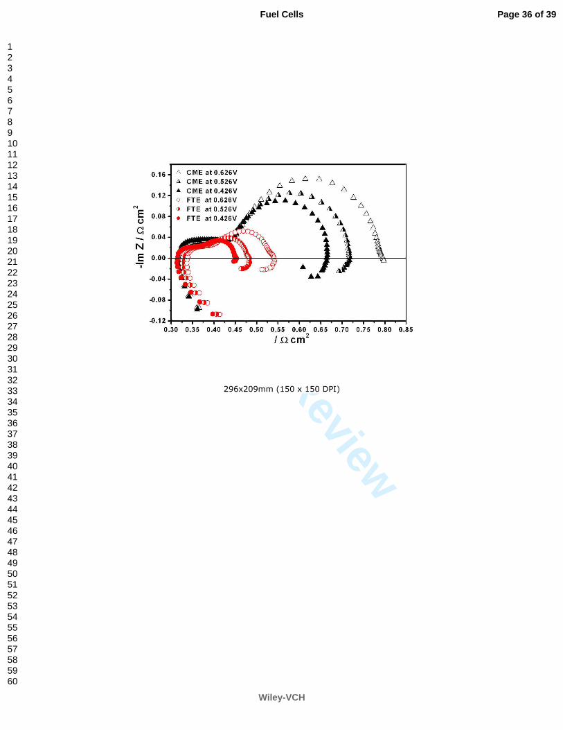
Electrochemical impedance spectroscopy (EIS) of electrodes FTE and CME shown in
Figure 11 further confirms the above analysis in another vision. The EIS analysis is used to
resolve the frequency domain into the individual contributions of the various factors, ohmic,
kinetic and mass transport. The small arcs at the high frequencies shown in Figure 11 are
related to the outer electrode porosity over the electroactive region [43, 44] independent of
Page 16 of 39
Wiley-VCH
Fuel Cells
123456789101112131415161718192021222324252627282930313233343536373839404142434445464748495051525354555657585960
For Peer Review
17
the applied potentials, which are in agreement with its ohmic nature. Then inverted deduction,
if the whole real surface area of FTE is same as that of CME, the smaller arcs at the high
frequency for the FTE imply that the electroactive region of FTE is larger than that of CME
in the case of flooding, as a result compared with the CME the FTE can obtain a much larger
polarization current, which is in agreement with the above analysis.
The diameter of the medium and partial low frequencies arcs in Figure 11 is referred to
the polarization resistances (Rp), which is usually associated with the charge transfer across
the electrode/electrolyte interface. However, if the time scale of the charge-transfer process is
close to that of the slow oxygen diffusion processes responsible for the surface concentration
of the electroactive species, Rp may contain contributions from all types of processes, which
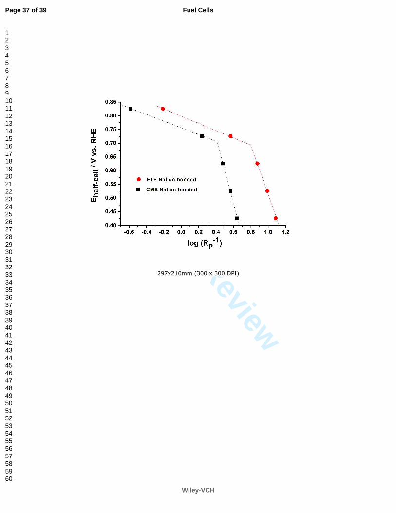
can be established through an analysis of the dependence of Rp on the cathode potential. In
Figure 12, the cathode potential (half-cell voltage) was represented as a function of log Rp-1
following the eq. (3) [45].
Vcath = E0 - b log Rp-1 (3)
The values of the intercept E0 and slope b are obtained from the linear plots in Figure 12.
There are two cases can be observed for the potential dependence of the resistance: (1) in a
range of the high half-cell voltages (e.g. 0.826V to 0.726 V) the slopes of the straight lines is
0.12 and 0.13 V/decade for the CME and FTE, respectively, which implies that the oxygen
diffusion is controlling the reaction kinetics [22] and should attribute to the agglomerate
diffusion (the progressive depletion of oxygen within a pore) according to the
thin-flim/flood-agglomerate model of gas diffusion electrodes developed by Raistrick [46,47];
(2) in a range of the low half-cell voltages (e.g. 0.626V to 0.426 V) the slopes of the straight
Page 17 of 39
Wiley-VCH
Fuel Cells
123456789101112131415161718192021222324252627282930313233343536373839404142434445464748495051525354555657585960
For Peer Review
18
lines is 1.2 and 0.95 V/decade for the CME and FTE, respectively, which means the oxygen
diffuses across an electrolyte film to the catalyst surface (thin film diffusion) [45,48].
Furthermore, the slope of the straight lines for the FTE is less than that for CME, which
implies that FTE can obtain a higher cathode potential (half-cell voltage) than CME at the
same condition.
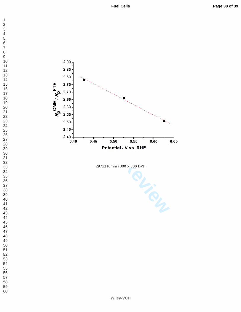
At lower cathode potentials the electrode kinetics may be controlled by mass transfer,
the main contribution of Rp comes from the oxygen diffusion resistance [49]. Therefore, the
higher oxygen solubility in DMS extremely reduces the Rp of half-cell with FTE than that in
CME at the same polarization potential. Moreover, the ratio of RpCME/Rp
FTE increases with the
cathode potential decrease in a form of linear relation as shown in Figure 13. It means that
the superiority capability of oxygen transfer and flooding-tolerant of FTE is more
outstanding at lower cathode potential.
4.3 Distribution of the DMS in the FTE
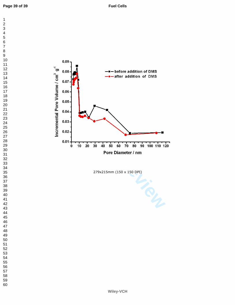
Figure 14 shows the difference in pore volumes of a CME before and after introduction
of the DMS. The main difference in pore volumes appears in the pores from 20 to 70 nm. It
suggests that the DMS mainly fills in the pores with meso-diameter from 20 nm to 70 nm. It
is the liquid electrolyte excessive condensation in the pores with a diameter from 20 to 70 nm
that cause so-called flooding of the electrode. The pores with a diameter below 20 nm may
always be occupied by water due to water capillary condensation in such small pores. The
pores with a diameter over 70 nm may primarily belong to the gas, and water can be easily
excluded by gas even though the large pores are occupied by water. Besides, due to the
smaller capillary pressure in pores larger than 70 nm, it is slightly more difficult for water to
Page 18 of 39
Wiley-VCH
Fuel Cells
123456789101112131415161718192021222324252627282930313233343536373839404142434445464748495051525354555657585960
For Peer Review
19
condense down in such large pores even though they become more hydrophilic owing to the
PTFE degradation. The water in the pores with a diameter from 20 to 70 nm, however, may
be not easily excluded because water capillary condensation in such pores is not as small as
that in large pores. Therefore, the liquid electrolyte prefers to flood oxygen electrode via the
pores with a diameter from 20 to 70 nm rather than that larger than 70 nm. The situation will
be different if the pores with a diameter from 20 to 70 nm were in advance occupied by oil,
such as DMS, which has a zero contact angle with carbon and Teflon, but 117° contact angle
with water [50]. It can be expected that DMS can well penetrate into the pores configured by
carbon and Teflon. Once the pores are occupied by DMS, the water-insoluble DMS is
unlikely to be washed out of the electrode by product water.
It should be noted that we can’t find any liquid medium which is better than void pores
for oxygen transport. A compromising way is how to make the pathway of the oxygen
transport as short as possible even though this pathway is filled by oil favorable to gas
dissolution and transport. The DMS should be limited in the pores that are subject to water
flooding rather than those void pores always belonging to gas phase, such as pores in the
back layer of a porous electrode.
4 Conclusions
A more flooding-tolerant electrode (FTE) for the oxygen reduction reaction in alkaline
was prepared by adding water-proof oil DMS into the conventional MnO2/C electrode
(CME). The FTE displays outstanding flooding-tolerant capability, especially in the case of a
large current density, in which mass transport of reaction gas is in a dominant position. The
success of FTE in flooding-tolerant is due to (1) DMS, in which the concentration of
Page 19 of 39
Wiley-VCH
Fuel Cells
123456789101112131415161718192021222324252627282930313233343536373839404142434445464748495051525354555657585960
For Peer Review
20
dissolved oxygen is over 10 and 30 times higher than that in 1 mol L-1 KOH at 25 and 80 °C,
respectively, supplies an channel with higher O2 transport through the liquid oil than through
liquid water and the higher solubility of oxygen in such DMS-filled channels as well as
higher penetration of gaseous O2 via the DMS into the electrode, (2) it partially mitigates the
effects of water flooding to the catalyst layer of oxygen electrode used in AFC and metal/air
batteries due to the PTFE degradation and physical wetting phenomenon in alkaline
electrolyte and (3) it appears to provide an oxygen pathway through pores with a diameter of
20 to 70 nm, in which flooding often happens and is not easy to overcome.
Acknowledgements
This work was financially supported by NSFC of China (Grant Nos. 20476109, 20806096,
20936008 and 20906107), by program 863 of the Chinese Ministry of Science and
Technology (Grant No. 2007AA05Z124), by Innovative Talent Training Project, Chongqing
University (S-09013), and by Science Research Foundation of SKL-PES
(2007DA10512708208).
References
[1]. M. Schulze, N. Wagner, T. Kaz, K. A. Friedrich, Electrochim. Acta 2007, 52, 2328.
[2]. M. Cifrain, K. V. Kordesch, J. Power Sources 2004, 127, 234.
[3]. P. Gouérec, L. Poletto, J. Denizot, E. Sanchez-Cortezon, J. H. Miners, J. Power Sources 2004, 129, 193.
[4]. E. Gülzow, N. Wagner, M. Schulze, Fuel cells 2003, 3, 67.
[5]. D. R. Sena, E. R. Gonzalez, E. A. Ticianelli, Electrochim. Acta 1992, 37, 1855.
[6]. N. Wagner, M. Schulze, E. Gülzow, J. Power Sources 2004, 127, 364.
Page 20 of 39
Wiley-VCH
Fuel Cells
123456789101112131415161718192021222324252627282930313233343536373839404142434445464748495051525354555657585960

For Peer Review
21
[7]. M. Schulze, C. Christenn, Appl. Surf. Sci. 2005, 252, 148.
[8]. M. Schulze, M. Lorenz, T. Kaz, Surf. Interf. Anal. 2002, 34, 646.
[9]. M. Schulze, K. Bolwin, E. Gülzow, W. Schnurnberger, Fresenius J. Anal. Chem. 1995, 353, 778.
[10]. E. Gülzow, M. Schulze, Degradation of nickel anodes during operation in alkaline fuel cells, in:
Proceedings of the Fuel Cell Seminar, Palm Springs, November, 2002.
[11]. M. Schulze, E. Gu¨lzow, G. Steinhilber, Appl. Surf. Sci. 2001, 179, 251.
[12]. S. D. Song, H. M. Zhang, X. P. Ma, Z.-G. Shao, Y. N. Zhang, B. L. Yi, Electrochem. Commun. 2006, 8,
399.
[13]. M. Maja, C. Orecchia, M. Strano, P. Tosco, M. Vanni, Electrochim. Acta 2000, 46, 423.
[14]. G.-Q. Zhang, X.-G. Zhang, Y.-G. Wang, Carbon 2004, 42, 3097.
[15]. MA Al-Saleh, S Gultekin, AS Al-Zakri, H Celiker, J. Appl. Electrochem. 1994, 24, 575.
[16]. D. R. Lide, Handbook of Chemistry and Physics , ed. 81st, CRC Press, Boca Raton, FL, 2000–2001, pp.
8–103.
[17]. K. V. Kordesch, Brennstoffbatterien, Springer–Verlag, Wien, New York, 1984.
[18]. PD Michael, An assessment of the prospects for fuel cell-powered cars, ETSU, United Kingdom, 2000.
[19]. K Kordesch, S Gunter,Fuel cells and their applications, Wiley-VCH, Berlin, Germany, 1996.
[20]. AJ Appleby, FR Foulkes, Fuel cell handbook, Krieger Publishing Company, Malabar, Florida, 1993.
[21]. G. F. McLean, T. Niet, S. Prince-Richard, N. Djilali, Int. J. Hydrogen Energy 2002, 27, 507.
[22]. H. Huang, W. K. Zhang, M. C. Li, Y. P. Gan, J. H. Chen, Y. F. Kuang, J. Colloid Interface Sci. 2005, 284,
593.
[23]. Ch.-Ch. Yang, S.-T. Hsu, W.-Ch. Chien, M. Ch. Shih, Sh.-J. Chiu, K.-T. Lee, Ch. L. Wang, Int. J.
Hydrogen Energy 2006, 31, 2076.
Page 21 of 39
Wiley-VCH
Fuel Cells
123456789101112131415161718192021222324252627282930313233343536373839404142434445464748495051525354555657585960

For Peer Review
22
[24]. M. Bursell, M. Pirjamali, Y. Kiros, Electrochim. Acta 2002, 47, 1651.
[25]. W. H. ZHU, B. A. POOLE, D. R. CAHELA, B. J. TATARCHUK, J Appl Electrochem 2003, 33, 29.
[26]. Y. Kiros, S. Schwartz, J. Power Sources 1991, 36, 547.
[27]. G. Velayutham, J. Kaushik, N. Rajalakshmi, K. S. Dhathathreyan, Fuel cells 2007, 7, 314.
[28]. E. Gülzow, Fuel cells 2004, 4, 251.
[29]. Z. D. Wei, W. Z. Huang, S. T. Zhang, J. Tan, J. Power Sources 2000, 91, 83.
[30]. D.J.G. Ives, G.J. Janz, Reference Electrodes: Theory and Practice, Academic Press, New York, 1961.
[31]. S. M Xing, Y. L. Wang, Synthetic Technics and Product Application of Organic Silicon, Chemical Industry
Press, Beijing, 2000.
[32]. S.K. Shoor, R.D. Walker, K.E. Gubbins, J. Phys. Chem. 1969, 73, 312.
[33]. R.H. Li, Elements of Mass Transfer, Beijing Aviation College Press, Beijing, 1987.
[34]. J. Giner, C. Hunter, J. Electrochem. Soc. 1969, 116, 1124.
[35]. A. J. Bard, L. R. Faulkner, Electrochemical Methods, Wiley & Sons, New York, 1980.
[36]. I. Roche, E. ChaÎnet, M. Chatenet, J. Vondrák, J. Phys. Chem. C 2007, 111, 1434.
[37]. V. S. Murthi, R. C. Urian, S. Mukerjee, J. Phys. Chem. B 2004, 108, 11011.
[38]. M. L. Calegaro, F. H. B. Lima, E. A. Ticianelli, J. Power Sources 2006, 158, 735.
[39]. L. Q. Mao, D. Zhang, T. Sotomura, K. Nakatsu, N. Koshiba, T. Ohsaka, Electrochim. Acta 2003, 48, 1015.
[40]. F. H. B. Lima, M. L. Calegaro, E. A. Ticianelli, J. Electroanal. Chem. 2006, 590, 152.
[41]. T. Ohsaka, L. Q. Mao, K. Arihara, T. Sotomura, Electrochem. Commun. 2004, 6, 273.
[42]. L. Jörissen, J. Power Sources 2006, 155, 23.
[43]. F. Alcaide, E. Brillas, P.-L. Cabot, J. Electroanal. Chem. 2003, 547, 61.
[44]. S. Ahn, BJ. Tatarchuk, J. Electrochem. Soc. 1995, 142, 4169.
Page 22 of 39
Wiley-VCH
Fuel Cells
123456789101112131415161718192021222324252627282930313233343536373839404142434445464748495051525354555657585960

For Peer Review
23
[45]. M. Ciureanu, R. Roberge, J. Phys. Chem. B 2001, 105, 3531.
[46]. T. E. Springer, I. D. Raistrick, J. Electrochem. Soc. 1989, 136, 1594.
[47]. I. D. Raistrick, Electrochim. Acta 1990, 25, 1579.
[48]. L. Genies, Y. Bultel, R. Faure, R. Durand, Electrochim. Acta 2003, 48, 3879.
[49]. L. Giorgi, E. Antolini, A. Pozio, E. Passalacqua, Electrochim. Acta 1998, 43, 3675.
[50]. R. H. Wu, M. J. Sun, Surface and Interface of High Polymer, Science Press, Beijing, 1998.
Page 23 of 39
Wiley-VCH
Fuel Cells
123456789101112131415161718192021222324252627282930313233343536373839404142434445464748495051525354555657585960
For Peer Review
24
Figure Captions
Fig. 1 Schematic diagram of anti-flooding in catalyst layer of conventional electrode (CME) and
flooding-tolerant electrode (FTE).
Fig. 2 The structure of oxygen electrode and half-cell. (a) Two sides of oxygen electrode, (b) gold ring current
collector, (c) rubber cushion, (d) Teflon holder, (e) gas chamber, (f) inlet and (g) outlet of gas reactant.
Fig. 3 Chronopotentiometry of electrodes Nafion-bonded FTE and CME under modulation of gradually
increased current in O2-saturated 1 mol L-1 KOH (O2 fed at 10 mL min-1).
Fig. 4 Chronopotentiometry of electrodes Nafion-bonded FTE and CPE at fixed cathode current of 60 mA cm-2
in O2-saturated 1 mol L-1 KOH (O2 fed at 10 mL min-1).
Fig. 5 Chronoamperometry of electrodes Nafion-bonded FTE and CME as the electrode potential jumps from
1.126 to 0.326 V in O2-saturated 1 mol L-1 KOH (O2 fed at 10 mL min-1).
Fig. 6 Chronoamperometry of half-cell with cathodes PTFE-bonded FTE and CME as cathode potential jumps
from 1.126 to 0.326 V in 1 mol L-1 KOH (O2 fed at 60 mL min-1).
Fig. 7 Chronopotentiometry of half-cell with cathodes PTFE-bonded FTE and CME as cathode under
modulation of gradually increased current in 1 mol L-1 KOH (O2 fed at 60 mL min-1).
Fig. 8 Cell voltage vs. Current density of a half-cell with cathodes CME and an FTE as cathode at scan rate of 2
mV s-1 in 1 mol L-1 KOH (O2 fed at 60 mL min-1).
Fig. 9 Cell voltage vs. Current density of a half-cell with cathodes CME and an FTE as cathode at scan rate of 2
mV s-1 in 1 mol L-1 KOH (Air self-breathing).
Fig. 10 Chronopotentiometry of a half-cell with cathodes PTFE-bonded FTE and CME as cathode under
modulation of gradually increased current in 1 mol L-1 KOH (Air self-breathing).
Fig. 11 Potential dependence of the Nyquist plots obtained for an half-cell with cathodes Nafion-bonded FTE
and CME as cathode in 1 mol L-1 KOH (1×10⁴ to 1×10⁻² Hz;O2 fed at 60 mL min-1).
Fig. 12 Cathode potential vs log(Rp-1) for an half-cell with Nafion-bonded CME and Nafion-bonded FTE in 1
mol L-1 KOH (O2 fed at 60 mL min-1).
Fig. 13 Rp ratio of Nafion-bonded CME to Nafion-bonded FTE as a function of the cathodic potential for an
half-cell in 1 mol L-1 KOH (O2 fed at 60 mL min-1).
Fig. 14 Change in pore volume of a CME before and after addition of 2.5 mg cm-2 DMS (the CME has apparent
area of 4 cm2).
Page 24 of 39
Wiley-VCH
Fuel Cells
123456789101112131415161718192021222324252627282930313233343536373839404142434445464748495051525354555657585960

For Peer Review
25
Table
Table 1 Oxygen diffusion limiting current densities il (mA cm-2) of the ORR vs the effective diffusion
thickness L in the liquid phase of the catalyst layer (170 µm) at 25 and 80 °C, respectively.
L / µm 0.1 0.2 0.5 0.8 1.0 1.5 2.0
°C 25 80 25 80 25 80 25 80 25 80 25 80 25 80
CME 465 165 232.5 82.5 93 33 58 20.6 46.5 16.5 31 11 22.3 8.2
FTE 3000 3000 1500 1500 600 600 375 375 300 300 200 200 150 150
Page 25 of 39
Wiley-VCH
Fuel Cells
123456789101112131415161718192021222324252627282930313233343536373839404142434445464748495051525354555657585960

For Peer Review
151x194mm (72 x 72 DPI)
Page 26 of 39
Wiley-VCH
Fuel Cells
123456789101112131415161718192021222324252627282930313233343536373839404142434445464748495051525354555657585960
For Peer Review
192x213mm (72 x 72 DPI)
Page 27 of 39
Wiley-VCH
Fuel Cells
123456789101112131415161718192021222324252627282930313233343536373839404142434445464748495051525354555657585960

For Peer Review
297x210mm (300 x 300 DPI)
Page 28 of 39
Wiley-VCH
Fuel Cells
123456789101112131415161718192021222324252627282930313233343536373839404142434445464748495051525354555657585960
For Peer Review
297x210mm (300 x 300 DPI)
Page 29 of 39
Wiley-VCH
Fuel Cells
123456789101112131415161718192021222324252627282930313233343536373839404142434445464748495051525354555657585960
For Peer Review
297x210mm (300 x 300 DPI)
Page 30 of 39
Wiley-VCH
Fuel Cells
123456789101112131415161718192021222324252627282930313233343536373839404142434445464748495051525354555657585960
For Peer Review
297x210mm (300 x 300 DPI)
Page 31 of 39
Wiley-VCH
Fuel Cells
123456789101112131415161718192021222324252627282930313233343536373839404142434445464748495051525354555657585960

For Peer Review
297x210mm (300 x 300 DPI)
Page 32 of 39
Wiley-VCH
Fuel Cells
123456789101112131415161718192021222324252627282930313233343536373839404142434445464748495051525354555657585960

For Peer Review
297x210mm (300 x 300 DPI)
Page 33 of 39
Wiley-VCH
Fuel Cells
123456789101112131415161718192021222324252627282930313233343536373839404142434445464748495051525354555657585960
For Peer Review
297x210mm (300 x 300 DPI)
Page 34 of 39
Wiley-VCH
Fuel Cells
123456789101112131415161718192021222324252627282930313233343536373839404142434445464748495051525354555657585960
For Peer Review
297x210mm (300 x 300 DPI)
Page 35 of 39
Wiley-VCH
Fuel Cells
123456789101112131415161718192021222324252627282930313233343536373839404142434445464748495051525354555657585960
For Peer Review
296x209mm (150 x 150 DPI)
Page 36 of 39
Wiley-VCH
Fuel Cells
123456789101112131415161718192021222324252627282930313233343536373839404142434445464748495051525354555657585960
For Peer Review
297x210mm (300 x 300 DPI)
Page 37 of 39
Wiley-VCH
Fuel Cells
123456789101112131415161718192021222324252627282930313233343536373839404142434445464748495051525354555657585960
For Peer Review
297x210mm (300 x 300 DPI)
Page 38 of 39
Wiley-VCH
Fuel Cells
123456789101112131415161718192021222324252627282930313233343536373839404142434445464748495051525354555657585960
For Peer Review
279x215mm (150 x 150 DPI)
Page 39 of 39
Wiley-VCH
Fuel Cells
123456789101112131415161718192021222324252627282930313233343536373839404142434445464748495051525354555657585960