a model based on preview mechanism of driver … · a model based on preview mechanism of driver...
TRANSCRIPT

U.P.B. Sci. Bull., Series D, Vol. 80, Iss. 2, 2018 ISSN 1454-2358
A MODEL BASED ON PREVIEW MECHANISM OF DRIVER
FOR THE ELECTRONIC STABILITY PROGRAM
Gu JUN1, Lin XIAONING2, Huang MANHONG3
Reference model is the benchmark for vehicle dynamics control. However, the
time delay from the driving intention to the reference model output will aggravate
the instability of vehicle under limit working conditions. Therefore, a reference
model based on preview mechanism of driver is proposed to reduce the influence of
the time delay. Firstly, the preview mechanism of driver is used to compute the
predicted steering wheel angle, which can enhance the driving intention. Then, the
reference model is established by combining the steering angle of driver input and
the predicted steering wheel angle. Secondly, the yaw moment controller is designed
according to the sliding control theory and the required yaw moment is allocated
according to the quadratic programming theory. Finally, simulation results show
that the vehicle stability control system based on the proposed reference model has a
better performance than the traditional control system, and the proposed method is
able to improve the control intervention instant.
Keywords: Electronic Vehicle, ESP System, Reference Model, Driving Intention
1. Introduction
Electronics Stability Program (ESP) system is one kind of new active
security technology. Recently, ESP system has been a new vehicle safety standard
for all light vehicle. During the transient steering process, the output value of
reference model is regarded as the most important driving intention variable to
realize the driving operation, which is the tracking goal for ESP system.
In order to obtain a good maneuverability, the reference model has been
studied and different models were put forward by the researchers [1-3]. According
to human drivers are familiar with the linear handling characteristics, Nagai et al.
[1] proposed a reference model for ESP system, which is based on the Tow
Degree of Freedom (2DOF) vehicle model. Moreover, Geng C et al. [2] modified
1 College of Information and Mechanical and Electrical Engineering, Jiangsu Open University,
Nanjing Jiangsu 210019, China; E-mail:[email protected] 2 College of Information and Mechanical and Electrical Engineering, Jiangsu Open University,
Nanjing Jiangsu 210019, China.E-mail:[email protected] 3 College of Energy and Power Engineering, Nanjing University of Aeronautics and Astronautics,
Nanjing Jiangsu 210016, China.E-mail:[email protected]

128 Gu Jun, Huang Manhong
the 2DOF reference model by considering the road adhesion to limit the lateral
acceleration. But these reference models cannot stabilize the vehicle adequately
under limited working conditions. Therefore, Jonasson et al. [3] proposed a
reference model that is constrained by side slip angle to improve the vehicle
stability.
However, as the reference models continuous improvement, the vehicle
has still happened to instability under limited working conditions. The reasons for
this situation are the fuzziness of driving intention, the parameter uncertainty with
the vehicle and so on. Therefore, the research scholars proposed the other
reference models aiming to solve these problems [4-5]. Raksincharoensak et al. [4]
used Hidden Markov Model to predict the driver’s steer intention, and enhanced
the reference model’s driving intention via this information. Xiong et al. [5]
proposed a tire cornering stiffness estimation method to ensure the control
robustness against environmental disturbances as well as parameter uncertainty,
which can modify the output value of reference model. However, even if the
reference model could be properly modified, a vehicle dynamics stability
controller might still not achieve a satisfactory result, because there is a delay
while the output value of reference model response to the driving intention.
A number of tests have shown the existence of that delay. The delay
mainly caused by the neural response of driver and steering system of vehicle, and
varies from 100ms to 300ms depending on the driver’s reaction time,
maneuvering conditions and the road conditions [6]. However, the control
intervention instant can be brought forward to some degree with a driver model.
Chen et al. [7] proposed a new method to enhance the driving intention of
reference model based on a single point preview driver model [8], which can
predict the driver’s intention. However, papers about the driver model to improve
the control intervention are seen rarely. Thus, this paper proposes a novel
reference model based on the driver’s preview mechanism. The reference model
can enhances its driving intention by introducing prediction of steering wheel
angle, which can be obtained via a direction preview driver model [9]. In order to
minimize the influence on the driver’s operation, it uses fuzzy control method to
establish the reference model.
This paper is arranged as follows. The second section describes the
specific method of the proposed ESP system. Simulation results of the two ESP
systems are shown, and a comparison is made between these two kinds of ESP
system in the third section. Finally, conclusions are drawn in the fourth section.
A model based on preview mechanism of driver for the electronic stability program 129
2. ESP System
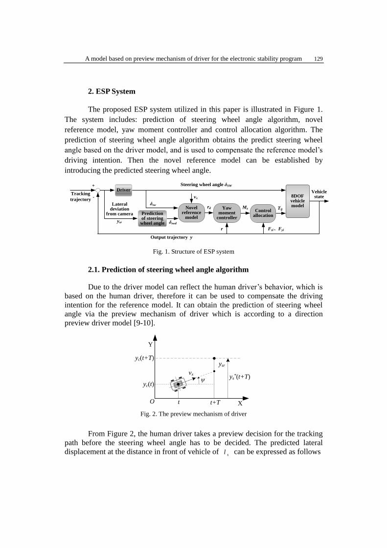
The proposed ESP system utilized in this paper is illustrated in Figure 1.
The system includes: prediction of steering wheel angle algorithm, novel
reference model, yaw moment controller and control allocation algorithm. The
prediction of steering wheel angle algorithm obtains the predict steering wheel
angle based on the driver model, and is used to compensate the reference model’s
driving intention. Then the novel reference model can be established by
introducing the predicted steering wheel angle.
-Tracking
trajectory
Driver
Mz
Steering wheel angle δSW
8DOF vehicle model
+
Vehicle state
Lateral deviation
from camera
TijControl allocation
δsw
Output trajectory y
r Fzi、Fyi
Yaw moment
controller
Novel reference
model
rd
Prediction of steering
wheel angle δswd
vx
ysr
Fig. 1. Structure of ESP system
2.1. Prediction of steering wheel angle algorithm
Due to the driver model can reflect the human driver’s behavior, which is
based on the human driver, therefore it can be used to compensate the driving
intention for the reference model. It can obtain the prediction of steering wheel
angle via the preview mechanism of driver which is according to a direction
preview driver model [9-10].
X
Y
yc(t)
yc(t+T)
vx
ysr
ψ
O t+Tt
ys*(t+T)
Fig. 2. The preview mechanism of driver
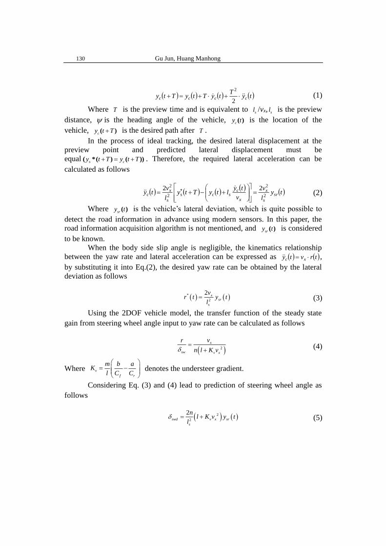
From Figure 2, the human driver takes a preview decision for the tracking
path before the steering wheel angle has to be decided. The predicted lateral
displacement at the distance in front of vehicle of s
l can be expressed as follows
130 Gu Jun, Huang Manhong
( ) ( ) ( ) ( )tyT
tyTtyTty cccc ++=+
2
2
(1)
Where T is the preview time and is equivalent to s
l /vx, sl is the preview
distance, is the heading angle of the vehicle, c
y t( ) is the location of the
vehicle, c
y t T+( ) is the desired path after T .
In the process of ideal tracking, the desired lateral displacement at the
preview point and predicted lateral displacement must be
equals c
y t T y t T+ = +( *( ) ( )) . Therefore, the required lateral acceleration can be
calculated as follows
( ) ( ) ( )( )
( )tyl
v
v
tyltyTty
l
vty sr
s
x
x
cscs
s
xc 2
2
2
2 22=
+−+=
(2)
Where sr
y t( ) is the vehicle’s lateral deviation, which is quite possible to
detect the road information in advance using modern sensors. In this paper, the
road information acquisition algorithm is not mentioned, and sr
y t( ) is considered
to be known.
When the body side slip angle is negligible, the kinematics relationship
between the yaw rate and lateral acceleration can be expressed as ( ) ( )trvty xc = ,
by substituting it into Eq.(2), the desired yaw rate can be obtained by the lateral
deviation as follows
( ) ( )*
2
2 x
sr
s
vr t y t
l= (3)
Using the 2DOF vehicle model, the transfer function of the steady state
gain from steering wheel angle input to yaw rate can be calculated as follows
( )2
x
sw v x
vr
n l K v=
+ (4)
Where v
f r
m b aK
l C C
= −
denotes the understeer gradient.
Considering Eq. (3) and (4) lead to prediction of steering wheel angle as
follows
( ) ( )2
2
2swd v x sr
s
nl K v y t
l = + (5)

A model based on preview mechanism of driver for the electronic stability program 131
2.2. Proposed reference model
vx
EC
δ*SW
Fuzzy controller
-
δsw
+ E
d
dt
δswd
(b)
+
+
2DOF model with
restric conditions
rd
Δδ
(a)
δsw
2DOF model with
restric conditions
rd
vx
(a) the traditional reference model; (b) the novel reference model
Fig. 3. Difference between two reference models
The role of the reference model is to calculate the desired yaw rate, which
can provide the tracking goal for the yaw moment controller. In Figure 3(a),
2DOF model is widely used as a traditional reference model because human
drivers are very familiar with the linear handling characteristics [1]. Based on this
model, the desired yaw rate rd can be derived from the steering wheel angle δsw
and longitudinal vehicle velocity x
v as
( )2
x sw
d
v x
vr
nl K v
=
+ (6)
Besides, assuming the friction coefficient is μ, and in order to avoid large
lateral acceleration that exceeds tire cornering capability, the desired yaw rate is
constrained as
0.85d
x
gr
v
(7)
In fact, the yaw rate response to the steering angle is the first-order delay
system. Therefore, the desired yaw rate can be described as follows
( )2
1min , 0.85 sgn
1
x sw
d sw
x rv x
v gr
n v sl K v
=
++ (8)
Where r
the delay is time and sgn is a sign function.
The traditional reference models depend on the driver’s output steering
wheel angle, which characterizes the driving intention. Although this steering
wheel angle has strong robustness and adapts to different road conditions, it limits
the driver’s physiological conditions and vehicle structure. This means that sw
doesn’t reflect the driver’s intention adequately. Compared with sw
, the predicted
steering wheel angle swd
is not constrained by these conditions and is an ideal

132 Gu Jun, Huang Manhong
tracking goal for the vehicle, which can reduce the influence of these conditions.
However, if the predicted steering wheel angle can combine with the
steering wheel angle by human driver, it could not only enhance the driving
intention of reference model, but also improve the stability of vehicle. Therefore,
the novel reference model proposed in this article uses fuzzy control method as it
is shown in Figure 3(b). Due to fuzzy logic control can be used to deal with
complicated non-linear dynamic control problems, which is a non-linear control
method [11-12]. There are two main advantages of fuzzy models in comparison
with conventional mathematical models. The one is the possibility of elaborating
them on the basis of far fewer amounts of information about a system. The other
one is that fuzzy logic enables the heuristic rule-based techniques to be extended
for use in the continuously variable situation without significantly. In this context,
the number of applications of fuzzy logic to vehicle has increased significantly
over the last years with good results [13].
The architecture of fuzzy logic controller consists of three steps:
(i) Fuzzification
Two input variables for the fuzzy logic control are the error between the
human driver’s steering wheel angle and predicted steering wheel angle, i.e.
sw swdE = − , and the error between the human driver’s steering wheel angle rate
and predicted steering wheel angle rate, i.e. swdswEC −= . The output variable is
the steering wheel angle adjustment .
To provide enough rule coverage, seven fuzzy sets are used for input
variables: PB (positive big), PM (positive medium), PS (positive small), ZO
(zero), NB (negative big), NM (negative medium), and NS (negative small).
Similarly, the output variables are also fuzzified into seven fuzzy sets: {NB, NM,
NS, ZO, PS, PM, PB}.
(ii) Fuzzy decision process
It processes a list of rules from the knowledge base using fuzzy input from
the previous step to produce the fuzzy output. Table 1 shows rules for the
proposed fuzzy logic controller. These rules are introduced based on expert
knowledge and extensive simulations performed in this study. The steering wheel
angle adjustment mainly influences on steering wheel angle sw
. For this
reason, the rules follow the next criteria:
If sw swd
E = − is positive that means the vehicle is oversteer, it occurs
that:
sw
> 0 and swd
> 0 with sw
>swd
. In this case, it is necessary to
generate a negative that swd
to decrease sw
.
sw
< 0 and swd
< 0 with sw
<swd
. In this case, it is necessary to
generate a positive that swd
to increase sw
.

A model based on preview mechanism of driver for the electronic stability program 133
If sw swd
E = − is negative that means the vehicle is understeer, it occurs
that:
sw
> 0 and swd
> 0 with sw
<swd
. In this case, it is necessary to
generate a positive that swd
to increase sw
.
sw
< 0 and swd
< 0 with sw
>swd
. In this case, it is necessary to
generate a negative that swd
to decrease sw
.
The higher the difference between the steering wheel angle and predicted
steering angle, the higher the steering wheel angle is adjusted. Meanwhile the
error rate EC will be considering into the adjusting process, which is
characterized the degree of steering urgency. Table 1.
Fuzzy control rule for
EC E
PB PM PS ZO NS NM NB
PB NB NB NB NB NM NS ZO
PM NB NB NB NM NM NS PS
PS NB NB NM NS ZO PS PS
ZO NB NM NS ZO PS PM PB
NS NS NS ZO PS PM PB PB
NM NS PS PM PM PB PB PB
NB ZO PS PM PB PB PB PB
Rules based on the criteria above, we can tune considering the effect on
the vehicle state’s response lots of simulations. The fuzzy controller uses the
Mamdani Fuzzy Inference System (FIS), which is characterized by the following
fuzzy rule schema:
IF E is A and EC is B THEN is C
Where A and B are fuzzy sets defined on the input and output domains
respectively.
(iii) Defuzzification
It scales and maps the fuzzy out from fuzzy decision process to produce an
output, which is the input to the system controller. In this case, the steering wheel
angle adjustment. The defuzzification method used in this project is the center of
area. This method determines the center of the area below the combined
membership function.
Figure 4 shows the membership functions and ranges of values of E, EC
and respectively. The universe of discourse of inputs and output are

134 Gu Jun, Huang Manhong
normalized in the range of [-7 7].
-6 -4 -2 0 2 4 6
0
0.2
0.4
0.6
0.8
1
Steering wheel angle error E
Deg
ree
of
mem
ber
ship
NB NM NS ZO PS PM PB
-6 -4 -2 0 2 4 6
0
0.2
0.4
0.6
0.8
1
Steering Wheel angle error rate EC
Deg
ree
of
mem
ber
ship
NB NM NS ZO PS PM PB
(a) Input E (b) Input EC,
-6 -4 -2 0 2 4 6
0
0.2
0.4
0.6
0.8
1
Steering wheel angle adjustment U
Deg
ree
of
mem
ber
ship
NB NM NS ZO PS PM PB
(c) Output
Fig. 4. Membership functions of input and output variables:
After the Fuzzy controller outputs the steering wheel angle adjustment, the
desired steering wheel angel can be written as
*
sw sw = + (9)
Combined with Eq. (9) and (8), the desired yaw rate described as follows
( )*
* *
2
1min , 0.85 sgn
1
x sw
d sw
x rv x
v gr
n v sl K v
=
++ (10)
2.3 Yaw Moment Controller
The yaw moment controller is to ensure that the desired yaw rate is
realizable. Considering the nonlinear characteristics of vehicle, the sliding control
theory is beneficial to solve this problem [14]. Therefore, this paper uses the
sliding control theory to design the controller.The sliding surface S is defined as
dS r r= − , differentiating it and combining Eq. (10) yields, it can be written as
( ) dzsw
fx
rffr
zd rM
nbc
v
bcacacbc
IrreS −
++
+−−=−==
221
(11)
To make the system slide to the sliding surface S , the exponential
converging velocity is defined as ( )SKSS sgn−−= , where K and ε are the

A model based on preview mechanism of driver for the electronic stability program 135
positive gains.
Then, implementing the convergence condition of sliding mode control, the
required yaw moment z
M is obtained from Eq. (11) as follows
( )
−−+−
++
−−= SKSr
nI
ac
vI
bcac
I
acbcIM d
sw
z
f
z
rf
z
frzz sgn
22
(12)
According to Lyapunov stability criterion, the stability of control system
needs to be proved. The Lyapunov function is structured as 2 2
2L
V S= / , then make
a derivation to it and combine dS r r= − yields
−++
+−
−== d
z
zsw
z
f
xz
rf
z
frL r
I
M
nI
bc
vI
bcac
I
acbcSSSV
22
2 (13)
Substituting Eq. (12) into Eq. (13) with proper simplification as follows
( )( )SKSSSSVL sgn2 −−== (14)
Because S , ssgn( ) , K and are the positive, therefore the 2L
V is a
negative and this can be proved the control system is stable.
Besides, the controller uses a saturation function to alleviate clutch
chattering and improve its robustness by substituting sign function. In a similar
way, Eq. (12) can be written as follows
( )
−−+−
++
−−= SKSr
nI
ac
vI
bcac
I
acbcIM d
sw
z
f
z
rf
z
frzz sat
22
(15)
The saturation function is designed as follows
( )( )sgn
sat
S SS
S S
=
(16)
Where Δ is the boundary layer thickness.
2.4. Control allocation algorithm
The control allocation algorithm is designed to generate the total
longitudinal force xd
F and yaw moment zd
M . It requires for the controlled
vehicle to follow the reference model responses as well as to meet with the
driving intention. In order to allocate reasonable to realize the control target, this
paper uses the quadratic programming method to design the optimal allocation,
which is an effectively method to solve the controlled problem of over-actuated
systems [15].
136 Gu Jun, Huang Manhong
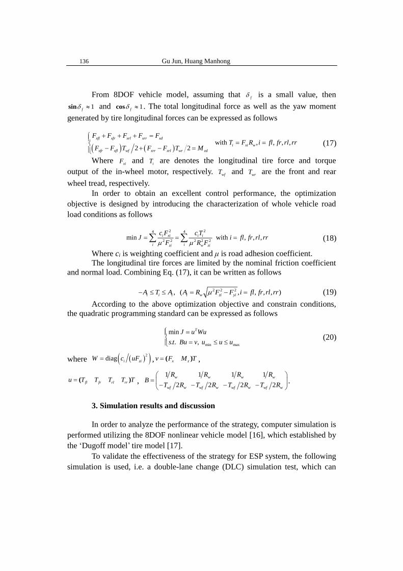
From 8DOF vehicle model, assuming that f is a small value, then
1f
sin and 1f
cos . The total longitudinal force as well as the yaw moment
generated by tire longitudinal forces can be expressed as follows
( ) ( ) with , , , ,
2 2
xfl xfr xrl xrr xd
i xi w
xfr xfl wf xrr xrl wr zd
F F F F FT F R i fl fr rl rr
F F T F F T M
+ + + == =
− + − =
(17)
Where xi
F and i
T are denotes the longitudinal tire force and torque
output of the in-wheel motor, respectively. wfT and
wrT are the front and rear
wheel tread, respectively.
In order to obtain an excellent control performance, the optimization
objective is designed by introducing the characterization of whole vehicle road
load conditions as follows
2 24 4
2 2 2 2 2min with , , ,i xi i i
i izi w zi
c F c TJ i fl fr rl rr
F R F = = = (18)
Where ci is weighting coefficient and μ is road adhesion coefficient.
The longitudinal tire forces are limited by the nominal friction coefficient
and normal load. Combining Eq. (17), it can be written as follows
2 2 2, ( , , , , )i i i i w zi yiA T A A R F F i fl fr rl rr− = − = (19)
According to the above optimization objective and constrain conditions,
the quadratic programming standard can be expressed as follows
min max
min
. . ,
TJ u Wu
s t Bu v u u u
=
= (20)
where ( )( )2diag i ziW c uF= , x z
v F M T= ( ) ,
fl fr rl rru T T T T T= ( ) ,
1 1 1 1
2 2 2 2
w w w w
wf w wf w wf w wf w
R R R RB
T R T R T R T R
=
− − − − .
3. Simulation results and discussion
In order to analyze the performance of the strategy, computer simulation is
performed utilizing the 8DOF nonlinear vehicle model [16], which established by
the ‘Dugoff model’ tire model [17].
To validate the effectiveness of the strategy for ESP system, the following
simulation is used, i.e. a double-lane change (DLC) simulation test, which can

A model based on preview mechanism of driver for the electronic stability program 137
reflect that the driver under the emergency operation of obstacle avoidance to the
response characteristics of vehicle. The responses of a vehicle with the proposed
ESP system is compared with the traditional ESP system, which is used the
traditional reference model as shown in Figure 5(a).
-0.5
0
0.5
1
1.5
2
2.5
3
3.5
4
y c
oo
rdin
ate
(m
)
0 20 40 60 80 100 120 140 160 180 200 220
x coordinate (m)
Proposed ESP
Traditional ESP
Desired Trajectory
-20
-15
-10
-5
0
5
10
15
Yaw
Rate
(deg
/s)
0 20 40 60 80 100 120 140 160 180 200 220
x coordinate (m)
Proposed ESP
Traditional ESP
(a)Trajectory tracking, (b)Yaw rate,
-2
-1.5
-1
-0.5
0
0.5
1
1.5
2
Sid
e S
lip
An
gle
(d
eg
)
0 20 40 60 80 100 120 140 160 180 200 220
x coordinate (m)
Proposed ESP
Traditional ESP
78
78.5
79
79.5
80
80.5
Lo
ngit
udin
al
Velo
cit
y (
km
/h)
0 20 40 60 80 100 120 140 160 180 200 220
x coordinate (m)
Proposed ESP
Traditional ESP
(c)Side slip angle, (d) Longitudinal velocity,
-60
-40
-20
0
20
40
60
Ste
eri
ng W
heel
Angle
(deg
)
0 20 40 60 80 100 120 140 160 180 200 220
x coordinate (m)
Proposed ESP
Traditional ESP
0 20 40 60 80 100 120 140 160 180 200 220
-60
-40
-20
0
20
40
60
x coordinate (m)
Refe
rence M
odel
Input
(deg)
s
Proposed ESPTraditional ESP
Adjustment quantity
(e) Steering wheel angle, (f) Reference model input
Fig. 5. Simulation comparison (V = 80 km/m, μ = 0.8)
Fig. 5 displays the proposed and traditional ESP control results at an initial
velocity of 80km/h and nominal friction coefficient μ is 0.8. From Fig. 5, both the
proposed ESP and traditional system can stabilize the vehicle to pass the DLC
path, the former obviously better than the latter such as Figure 5(a)~(c). Especially,

138 Gu Jun, Huang Manhong
in Figure 5(d) and (e), the vehicle final speed of the proposed ESP system is
higher than that of the traditional ESP system and the driver manipulate the
vehicle under the proposed ESP control with a smoother and smaller steering
wheel angle than the traditional ESP control, which can help the driver to relieve
the driving fatigue. It illustrates that proposed ESP had better performance than
the tradition ESP by the timely intervention to control vehicle.
-2
-1
0
1
2
3
4
y c
oo
rdin
ate
(m
)
0 20 40 60 80 100 120 140 160 180 200 220
x coordinate (m)
Proposed ESP
Traditional ESP
Desired Trajectory
-15
-10
-5
0
5
10
15
Yaw
Rate
(deg/s
)
0 20 40 60 80 100 120 140 160 180 200 220
x coordinate (m)
Proposed ESP
Traditional ESP
(a)Trajectory tracking, (b)Yaw rate,
-1.5
-1
-0.5
0
0.5
1
1.5
Sid
e S
lip
An
gle
(d
eg)
0 20 40 60 80 100 120 140 160 180 200 220
x coordinate (m)
Proposed ESP
Traditional ESP
36.5
37
37.5
38
38.5
39
39.5
40
40.5
Lo
ng
itu
din
al
Velo
cit
y (
km
/h)
0 20 40 60 80 100 120 140 160 180 200 220
x coordinate (m)
Proposed ESP
Traditional ESP
(c)Side slip angle, (d) Longitudinal velocity,
-100
-50
0
50
100
0 20 40 60 80 100 120 140 160 180 200 220
x coordinate (m)
Ste
eri
ng W
heel
Angle
(deg)
Proposed ESP
Traditional ESP
0 20 40 60 80 100 120 140 160 180 200 220-150
-100
-50
0
50
100
150
200
x coordinate (m)
s
Refe
ren
ce M
od
el
Inp
ut
(deg
)
Proposed ESPTraditional ESP
Adjustment quantity
(e) Steering wheel angle, (f) Reference model input
Fig. 6. Simulation comparison (V = 40 km/m, μ = 0.3)
Fig. 6 is the simulation results with an initial longitudinal velocity of
A model based on preview mechanism of driver for the electronic stability program 139
40km/h and nominal friction coefficient μ is 0.3. In this DLC condition, the
proposed ESP system is evidently better than the traditional ESP system from
Figure 6. As Figure 6(a)-(d) shown, the proposed ESP can have better
maneuverability and more potential to stabilize the vehicle. In the low friction
coefficient condition, the timely intervention made the great help for the vehicle to
stabilized vehicle. And it shows that the proposed ESP system not only solves the
time delay problem, but also improves the control intervention time.
4. Conclusions
(1) In this paper, a novel reference model is proposed based on the preview
mechanism of driver. In order to enhance the traditional reference model’s driving
intention, it used the prediction of steering wheel angle to compensate the driving
intention. The proposed reference model is established by the fuzzy control
method, which introduced the predicted steering wheel angle.
(2) Simulation results of the ESP system based on the proposed reference
model show a more responsive and better performance than a traditional method.
The proposed reference model and the new ESP control system are able to
improve the vehicle stability under critical situations.
Acknowledgements
This work was supported by the Natural Science Foundation of the Jiangsu
Higher Education Institutions of China [Grant Number 13KJB510005].
R E F E R E N C E S
[1]. Van Zanten A T. Bosch ESP systems: 5 years of experience. SAE Technical Paper, 2000.
[2]. Geng C, Mostefai L, Denaï M, et al. Direct yaw-moment control of an in-wheel-motored
electric vehicle based on body slip angle fuzzy observer, J. Industrial Electronics, IEEE
Transactions on, 2009, 56(5): 1411-1419.
[3]. Jonasson M, Andreasson J, Solyom S, et al., Utilization of actuators to improve vehicle
stability at the limit: From hydraulic brakes toward electric propulsion. Journal of Dynamic
Systems, Measurement, and Control, 2011, 133(5): 051003.
[4]. Raksincharoensak P, Mizushima T, Nagai M. Direct yaw moment control system based on
driver behavior recognition, J. Vehicle System Dynamics, 2008, 46(S1): 911-921.
[5]. Xiong L, Yu Z, Wang Y, et al., Vehicle dynamics control of four in-wheel motor drive electric
vehicle using gain scheduling based on tire cornering stiffness estimation. Vehicle System
Dynamics, 2012, 50(6): 831-846.
[6]. Zhu H, Li L, Jin M, et al. Real-time yaw rate prediction based on a non-linear model and
feedback compensation for vehicle dynamics control[J]. Proceedings of the Institution of
Mechanical Engineers Part D-Journal of Automobile Engineering, 2013, 227(10):
1431-1445.
140 Gu Jun, Huang Manhong
[7]. Chen Y, Hedrick J K, Guo K, A novel direct yaw moment controller for in-wheel motor electric
vehicles[J]. Vehicle System Dynamics, 2013, 51(6): 925-942.
[8]. Guo K, Guan H, Modelling of driver/vehicle directional control system. Vehicle System
Dynamics, 1993, 22(3-4): 141-184.
[9]. Y.S. Tan, H. Shen, M.H. Huang, Internal model control driver model with direction preview.
China Science paper. 2014, 9(11): 1275-1278.
[10]. Le T P, Stiharu I. An optimal preview driver model applied to a non-linear vehicle and an
impaired driver. Proceedings of the Institution of Mechanical Engineers, Part D: Journal of
automobile engineering, 2013, 227(4): 536-548.
[11]. Li Y, Tong S, Li T. Observer-based adaptive fuzzy tracking control of MIMO stochastic
nonlinear systems with unknown control directions and unknown dead zones. IEEE
Transactions on Fuzzy Systems, 2015, 23(4): 1228-1241.
[12]. Zhang RY, Huang H, Chen WW, et al., Coordinated control of ESP Based on Function
Allocation and Multi-objective Fuzzy Decision. Chinese Journal of Mechanical Engineering,
2014, 50(6): 99-106.
[13]. Aksjonov A, Augsburg K, Vodovozov V. Design and Simulation of the Robust ABS and ESP
Fuzzy Logic Controller on the Complex Braking Maneuvers. Applied Sciences, 2016, 6(12):
382.
[14]. Liu X, Xiong L, Yu ZP, et al. Experiment Research on Control Algorithm of ESP
System[C]//Applied Mechanics and Materials. Trans Tech Publications, 2013, 427:
838-841.
[15]. Klomp M. Longitudinal force distribution using quadratic ally constrained linear
programming. Vehicle System Dynamics, 2011, 49(12): 1823-1836.
[16]. Hsiao T. Robust wheel torque control for traction/braking force tracking under combined
longitudinal and lateral motion. IEEE Transactions on Intelligent Transportation Systems,
2015, 16(3): 1335-1347.
[17]. Liu W, He H, Peng J. Driving control research for longitudinal dynamics of electric vehicles
with independently driven front and rear wheels. Mathematical Problems in Engineering,
2013(2013)