a mechanical cell model and its application to cellular ...cdn.intechweb.org/pdfs/18660.pdf · the...
TRANSCRIPT

19
A Mechanical Cell Model and Its Application to Cellular Biomechanics
Yoshihiro Ujihara, Masanori Nakamura and Shigeo Wada Osaka University,
Japan
1. Introduction
1.1 Importance of understanding the mechanical behavior of cells
Cells are the structural and functional units of all living organisms. Cells are continually subjected to mechanical loads from a wide variety of sources. It is known that normal cellular functions, including motility (Haga et al. 2000), differentiation (Titushkin et al. 2007), and gene expression (Shieh and Athanasiou 2007) involve mechanical properties. To date, studies have provided a biochemical framework for understanding the mechanotransduction processes and responses of cells to mechanical stimuli (Cohen et al., 1997). Nevertheless, it remains controversial as to how cells sense mechanical stimuli and trigger subsequent biochemical reactions. Understanding these cellular behaviours and their underlying mechanisms could be advanced by exploring the mechanical properties of cells and the intracellular components that confer such mechanical properties.
1.2 Previous studies on cellular mechanics
To date, numerous studies have investigated the relationships between the mechanics of subcellular components and either the local (Wang, 1998; Titushkin et al. 2007) or the entire mechanical properties of the cell (Miyazaki et al., 2000; Nagayama et al., 2006). Although these studies have provided valuable information for understanding cellular mechanics, the highly complex and heterogeneous structures of the subcellular components, such as cytoskeletal filaments, result in difficulties in understanding their behaviour. For example, the diameter of actin filaments is of the order of submicrometers, actin filaments are connected to the cell membrane and other cytoskeletal filaments, and the subcellular components frequently interact. Despite recent advances in imaging techniques, visualizing structural changes in actin filaments during cell deformation remains a challenging task. In this regard, no reported study has successfully measured the mechanical properties of cells while simultaneously observing the behaviour of subcellular components through quantification of their mechanical properties as a cell deforms. Thus, it is not yet feasible to understand the mechanical properties of cells from the level of subcellular components, solely on the basis of these experiments. Computational approaches can complement the experimental studies of cell mechanics. The currently developed computational approaches are classified into continuum and discrete approaches. Continuum approaches assume that the smallest length scale of interest is larger than the dimensions of the microstructure. Continuum approaches have been widely used to
www.intechopen.com

Biomedical Engineering – From Theory to Applications
470
describe how strains and stresses are distributed within a cell (Karcher et al., 2003; Vaziri et al., 2007). The disadvantage of a continuum model lies in its ability to deal with discrete components, such as cytoskeletons, making it difficult to interpret the mechanical behaviours and interactions with discrete components, and their contribution to the mechanical properties of a cell. In contrast to the continuum approaches, discrete approaches treat the cytoskeleton as the main structural component and have been developed, in particular, to investigate the cytoskeletal mechanics in adherent cells (Satcher and Dewey, 1996; Stamenović et al., 1996). The microscopic spectrin-network model was developed for suspended cells, such as erythrocytes, to investigate the contribution of the cell membrane and spectrin network to the large deformation of red blood cells (Boey et al., 1998; Li et al., 2005). The tensegrity model consists of stress-supported struts, which play the role of microtubules, and cable-like structures, which play the role of actin filaments (Ingber, 2003). The tensegrity model depicts the cytoskeleton as a prestressed network of interconnected filaments, investigating the effects on cellular shape and stiffness (Stamenović et al., 1996). Because the tensegrity model is quite conceptual and does not consider other cellular components, such as the cell membrane and cytoplasm, difficulties arise when relating its findings to the physical relationships between the mechanical properties of a whole cell and its subcellular components.
1.3 Basic concept of the mechano-cell model The mechanical properties of a cell are the result of the structural combination of subcellular components, such as the cell membrane, nuclear envelope, and cytoskeleton. To understand the underlying process of how these subcellular components contribute to the cell as a whole, it is essential to develop a cell model that displays continuum behaviour as a whole. Although one way to express the continuum nature of a cell is to use the continuum model, this has difficulties considering discrete elements, such as the cytoskeleton, which may reorient passively concomitant with cell deformation. Thus, we depict a cell as an assembly of discrete elements, including a cellular membrane, in an attempt to express the continuum behaviour of the cell as a whole. Using computational biomechanics in conjunction with experimental measurements, it should be possible to establish a new platform that helps to provide a more complete picture of cellular remodelling rather than the collection of information being solely dependent on the measurement technology.
2. Development of the mechano-cell model
2.1 Overview
We have developed a cell model, termed the "mechano-cell," that is capable of simulating the mechanical behaviour of a cell (Ujihara et al. 2010a). As shown in Fig. 1, the model
Cell membrane (CM)
Nuclear envelope (NE)
Cytoskeleton (CSK)
Fig. 1. Overview of the mechano-cell model.
www.intechopen.com

A Mechanical Cell Model and Its Application to Cellular Biomechanics
471
consists of the cell membrane (CM), nuclear envelope (NE), and cytoskeletons (CSKs). The model changes shape such that the sum of the various elastic energies generated during cell deformation converges towards a minimum.
2.2 Modelling of a cell membrane and a nuclear envelope
The CM and NE are lipid layers, reinforced with cytoskeletal networks (Fig. 2). The cytoskeletal networks are firmly anchored to the CM and NE via various transmembrane proteins and/or membrane-associated proteins. It was thus assumed that the cytoskeletal network would not tear from the CM and NE.
Lipid bilayer
Transmembrane proteinCytoskeleton
Fig. 2. Phase-contrast micrograph of a floating cell and schematic of the cell membrane structure. Scale bar = 10 μm.
In this study, the mechanical nature of the cytoskeletal network was included in the model of the CM and NE. The cytoskeletal networks beneath the CM and NE are known to resist in-plane deformation (stretch and area change), whereas the lipid bilayer is relatively permissive to in-plane deformation (Mohandas and Evans, 1994). Moreover, the CM and NE within cytoskeletal networks resist bending because of their thickness. Spring network modelling was adopted to express the mechanical nature of the CM and NE (Wada and Kobayashi, 2003). Figure 3(a) shows the networks of the CM and NE and Figure 3(b) illustrates a magnified view of the triangular meshes. The black dots on the vertexes of the mesh are nodes, and are linked by a spring of spring constant ks. Neighbouring elements are connected with a bending spring of spring constant kb to prevent membrane folding. ri is the positional vector of the node i, nl1 and nl2 are normal vectors to individual neighbouring meshes, and θl is the angle between nl1 and nl2. The stretching energy Ws and bending energy Wb generated are modelled as
sN
ijjss LLkW
1
2
0 )(2
1 (1)
2
1
1tan
2 2
bNl
b b ll
W k L
(2)
where Ns and Nb are the number of springs for stretching and bending, and L0j and Lj are the lengths of the spring in the natural state after deformation. The tangent function is adopted in eq. (2) to infinitize the energy when the membrane is completely folded (θl = π). By vector analysis, we rewrote eq. (2) as
www.intechopen.com

Biomedical Engineering – From Theory to Applications
472
1 2
1 21
11
2 1
bNl l
b b ll ll
W k L
n n
n n (3)
The resistances to changes in the surface area of the whole membrane and to an area change of a local element are both modelled. The former corresponds to the situation whereby lipid molecules can move freely over the cytoskeletal network, while the latter corresponds to the situation where movement of the lipid molecules is confined to a local element. The area expansion energy WA is thus formulated as a summation of the energy due to a change in the whole membrane area and due to a change in the local area:
22
0 00 0
0 01
1 1
2 2
eNe e
A A a eee
A A A AW k A k A
A A (4)
where A is the area of the whole membrane, subscript 0 denotes the natural state, and kA is a coefficient for the whole area constraint, Ae is the area of the element, ka is a coefficient for the local area constraint, and Ne is the number of elements. The total elastic energy stored is thus expressed as:
j jj j
s AbW W W W (5)
where j denotes CM (j = c) and NE (j = n).
nl1
i ri
ks
θl
kb
nl2
e
l
(b)(a)nl1
i ri
ks
θl
kb
nl2
e
l
(b)(a)
Fig. 3. (a) Mesh of the cellular membrane and nuclear envelope and (b) mechanical model of the cell membrane.
2.3 Modelling of CSK
As demonstrated in various studies (Wang, 1998; Nagayama et al., 2006), CSKs play a pivotal role in cellular mechanics. The CSK consists primarily of actin filaments, microtubules, and intermediate filaments (see Fig. 4). Here, these were modelled as CSK regardless of the type of cytoskeletal filament. For simplicity, a CSK is expressed as a straight spring that generates a force as a function of its extension. The energy WCSK generated is thus modelled as
20
1
1( )
2
CSKN
CSK CSK i ii
W k l l
(6)
where kCSK is the spring constant of the CSK, l0i and li are the length of CSKi at the natural state and after deformation, and NCSK is the total number of CSKs.
www.intechopen.com

A Mechanical Cell Model and Its Application to Cellular Biomechanics
473
(a) (b) (c)
Fig. 4. Confocal laser scanning micrographs of (a) actin filaments, (b) microtubules and (c) intermediate filaments in adherent fibroblasts. Scale bar = 50 μm.
2.4 Interaction between the cell membrane and nuclear envelope
The organelles and cytosol are present between the CM and NE. The interaction between the CM and NE is expressed by a potential function with respect their distance apart. Figure 5 shows a conceptual diagram and potential function of the interaction between the CM and NE. We define the potential energy ┐ij between node i on the CM and node j on the NE as
ij
tan ( 1 0)2 2┐
0 (0 )
ij ij
n ij
ij
y yk y
y
(7)
where kn is a parameter to express the interaction between the CM and NE, and yij = (dij – d0)/d0, dij is the distance between node i on the CM and node j on the NE, and d0 is the difference in the radius between the CM and NE at their natural state. The total potential energy ┐ is calculated by taking a summation of ┐ij as
1 1
┐ ┐c nn nN N
iji j
(8)
where cnN and n
nN are the number of nodes on the CM and NE, respectively.
-1 0 1
Po
ten
tia
l en
erg
y Ψ
ij
Distance ratio yij
Nuclear envelope
dijj i
Cell membrane
Nodes
Cell membrane
Nuclear envelope
Fig. 5. Interaction between the cell membrane and nuclear envelope.
www.intechopen.com

Biomedical Engineering – From Theory to Applications
474
2.5 Minimum energy problem
The shape of the CM and NE can be determined from the elastic energies of the CM, NE,
and CSKs, and from the interaction between the CM and NE if we provide constraints on
the volumes encapsulated by CM cV and NE nV . By vector analyses, energies (5), (6), and
(8) are rewritten as functions of the positional vector of nodal points ri. Thus, the shape of
the CM and NE were determined as a minimum energy problem under a volume constraint.
Mathematically, this is phrased as calculating the positional vectors that satisfy a condition
such that the total elastic energy Wt is minimum, under the constraint that the volume cV
and nV are equal to 0cV and 0
nV
Minimize Wt with respect to ri
┐c nt CSKW W W W (9)
subject to cV = 0cV and nV = 0
nV
where superscript c and n denote the CM and NE, and subscript 0 denotes the natural state. A volume elastic energy WV is introduced as
2
00
0
1
2
j jj j j
V V j
V VW k V
V
(10)
where j denotes the CM (j = c) and NE (j = n), and kV is the volume elasticity. Including eq. (10) in the minimum energy problem, eq. (9) is rewritten as
Minimize W with respect to ri
┐c n c nCSK V VW W W W W W (11)
2.6 Solving method
A cell shape is determined by moving the nodal points on CM and NE such that the total elastic energy W is minimized. Based on the virtual work theory, an elastic force Fi applied to node i is calculated from
ii
W Fr
(12)
where ri is the position vector of i. The motion equation of a mass point with mass m on node i is described as
i i im r r F (13)
where a dot indicates the time derivative, and is the artificial viscosity. Discretization of eq. (13) and some mathematical rearrangements yield
1N N
N i ii
m
m
v Fv
(14)
where v is the velocity vector, N is the computational step number, and is an increment of
time. The position of node i 1Ni
r is thus calculated from
www.intechopen.com

A Mechanical Cell Model and Its Application to Cellular Biomechanics
475
1 1N N Ni i i r r v (15)
2.6 Procedure for computation
A flowchart for the simulation is illustrated in Fig. 6. The flowchart has two iterative processes. The external loop is a real-time process, while the internal loop is instituted to minimize the elastic energy by a quasi-static approach. Based on the virtual work theory, an elastic force Fi applied to node i is obtained from eq. (12). It is followed by updating the positional vector r of the nodal points by eq. (15) and calculating the total elastic energy W.
If a changing ratio of the total elastic energy W is smaller than a tolerance , the boundary conditions are renewed to proceed to the next real-time step. If not satisfied, force F and positional vector rN of the nodal points are repeatedly calculated under the same boundary conditions.
START
Update node position rN
Calculate the total elastic energy WN
Calculate F
Yes
No
t = t+δ
Update boundary conditions
Define parameters
N = 0
N = N+1
?1
N
NN
W
WW
Internal loop
(Quasi-static process)
Define the initial position of all nodes
External loop
(Real-time process)
Fig. 6. Flowchart for the mechanical test simulation.
2.7 Parameter settings
The CM and NE were assumed as spheres at their natural state, with a diameter of 20 m and
10 m, respectively. In the model, Ns and Nb = 519, cnN and n
nN = 175, Ne = 346,
NCSK = 200 and = 1.0106 g/s. For the CM, m = 1.010-9 g, ks = 5.6105 g/s2,
kb = 9.0103 gm/s2, kA = 2.7107 g/s2, ka = 3.0106 g/s2, kV = 5.0106 g/(ms2). For the
NE, the mass was set to half of the CM, while the other parameters were set to double the CM.
www.intechopen.com

Biomedical Engineering – From Theory to Applications
476
The spring constants ks, kA, and ka were estimated by the tensile test simulations such that the elastic energy generated in the mechano-cell equaled the strain energy WD obtained when the CM was modelled as a continuum. According to the theory of continuum mechanics, the strain energy WD is defined as
1
1
2
eN
D ee
W A h
T
e eε Dε (16)
where Ne is the number of elements, Ae is the area of each element, and h is the thickness of
the CM, eT = (Xe, Ye, XYe) is the strain vector of each element. D is the elastic modulus
matrix under a plane strain condition. The parameters in eq. (16) were set to h = 0.5 m, elastic modulus of the CM ECM = 1000 Pa, and Poisson’s ratio v = 0.3 by reference to Feneberg et al. (2004) McGarry et al. (2004), and Mahaffy et al. (2004). Note that the elastic modulus and Poisson’s ratio appear in the elastic modulus matrix D.
0 2 4 6 8 100
0.1
0.2
0.3
0.4
0.5
Cell deformation D (μm)
En
erg
y
W(p
J) Ws + WA
WD
Fig. 7. Elastic energy of the in-plane deformations (Ws + WA) stored in the mechano-cell (solid line) and the strain energy WD obtained when the CM was modelled as a continuum (dashed line).
The spring constant of the bending spring kb was determined such that the bending energy Wb calculated from eq. (2) at the initial state of the cell equaled the bending energy WB analytically calculated (Wada and Kobayashi, 2003). Analytically, the bending energy WB of a sphere is given by
21 2
1( )
2BW B C C dA (17)
where B is the bending stiffness and C1 and C2 are the principal curvatures. Applying eq.
(17) to the cell, allowing ┑ to be CM and given that B = 2.010-18 J (Zhelev et al., 1994) and
C1 = C2 = 1/R0 (R0 = 10 m, initial radius of a cell), it follows that kb = 9.0103 gm/s2.
The spring constant of the CSK kCSK was set to 1.5106 g/s2, based on the elastic modulus of an actin bundle (Deguchi et al., 2005). The CSKs were assumed to have a natural length when the cell was in its natural state. The CSKs were chosen randomly from all possible candidates of CSKs that were made by connecting two nodes on the CM. The spring
www.intechopen.com

A Mechanical Cell Model and Its Application to Cellular Biomechanics
477
constants of the volume elasticity (kV) were determined to assure cell incompressibility. Because no data is presently available for kn, it was determined that the load-deformation curves obtained by the simulation, fit the range of the experimental data.
3. Tensile tests
3.1 Tensile tests
The mechanical behavior of a cell during a tensile test was simulated. The tensile test was simulated by fixing the nodes of CM at one side, while moving those at the opposite side in the direction of cell stretching.
3.2 Simulation results
Figure 8 shows the deformation behaviour of a cell in the tensile test where a fibroblast is stretched, obtained by simulation of the model (left) and experimentally (right). Similar to the experimental data, the simulation showed that the cell and nucleus were elongated in the stretched direction. CSKs were randomly oriented prior to loading and were passively aligned in the stretched direction as the cell was stretched.
Computational Experimental
Nucleus
CellNucleus
CSK
Cell
(µm)0 10 20 30 40 (µm)0 10 20 30 40
Fig. 8. Snapshots of a cell during the tensile test simulation (left) and experimental system (right). The scale is indicated at the bottom of the figure.
Load-deformation curves obtained from the simulation and experimental systems are presented in Fig. 9. Note that, in addition to the model with randomly oriented CSKs (Fig. 8), the data obtained from the models with parallel-oriented, oriented, and perpendicularly oriented CSKs, in addition to with no CSK are presented for comparison. The curve obtained from the simulation of the model with randomly oriented CSKs appeared to increase non-linearly. The curve of the model with randomly oriented CSKs lay within the variation of the experimentally obtained curves (simulation = 0.48 μN, experimental = 0.43-1.24 μN at 20 μm cell deformation). Moreover, the curves obtained from the experiments were between the curve of the parallel-oriented model and that of perpendicularly oriented model.
www.intechopen.com

Biomedical Engineering – From Theory to Applications
478
L
oa
d
F(μ
N)
Cell deformation D (μm)
0 10 200
0.2
0.4
0.6
0.8
1.0
155
Parallel-oriented
model
Perpendicularly oriented model
Randomly oriented model
No CSK model
Experiments (n = 10)
Fig. 9. Load-deformation curves obtained from the simulation and experimental system (n = 10).
0
0.01
0.02
0.03
0.04
0-5 5-10 10-15 15-20
Stiff
ne
ss
S(N
/m)
Cell deformation D (μm)
Fig. 10. Changes in cell stiffness of a model with randomly oriented CSKs with cell deformation.
An increase in the cell stiffness with cell elongation is manifested from Fig. 10 that illustrates the cell stiffness (S) of a model with randomly oriented CSKs between 0–5, 5–10, 10–15, and 15–20 μm deformation (D). The cell stiffness (S) increased by ~1.5-fold as the cell deformation (D) increased from 0 to 15 µm, while decreases were evident if the cell was stretched further. The increase in cell stiffness with cell elongation is explained by the realignment of CSKs. Figure 11 provides a histogram of the existence probability of the orientation angles (Pθ)
www.intechopen.com

A Mechanical Cell Model and Its Application to Cellular Biomechanics
479
of the CSKs of a randomly oriented model at a cell deformation (D) of 0, 10, and 20 µm. The CSKs at D = 0 µm were distributed uniformly over all angles. With elongation of the cell, the distribution of the orientation angle of the CSK became skewed towards 0° (Fig. 11), demonstrating that the CSKs tend to become passively aligned in the stretched direction. This passive re-alignment gradually increased the elastic resistance of the whole cell against the stretched direction, causing the load-deformation curve to be non-linear (Fig. 9).
0
0.1
0.2
0.3
30 60 900
CSK orientation angle
θ (deg)
Pro
ba
bili
ty
Pθ
0
0.1
0.2
0.3
30 60 900
CSK orientation angle
θ (deg)
Pro
ba
bili
ty
Pθ
0
0.1
0.2
0.3
30 60 900
CSK orientation angle
θ (deg)
Pro
ba
bili
ty
Pθ
(a) (b) (c)
Fig. 11. Histogram of the existence probability of the orientation angles Pθ of the CSK the randomly oriented model during a cell deformation (D) value of (a) 0, (b) 10, and (c) 20 µm.
Not all the CSKs were stretched as the cell elongated. Figure 12 shows a histogram of stretch ratios Pλ of the CSK of the randomly oriented model at a deformation D of 0, 10, and
Pro
ba
bili
ty
Pλ
0
0.2
0.4
0.6
0.8
1.0
CSK stretch ratio λ
Pro
ba
bili
ty
Pλ
0
0.2
0.4
0.6
0.8
1.0
CSK stretch ratio λ
Pro
ba
bili
ty
Pλ
0
0.2
0.4
0.6
0.8
1.0
CSK stretch ratio λ
(a) (b)
(c)
Fig. 12. Histogram of the stretch ratio Pλ of the CSK of the randomly oriented model at a cell deformation (D) value of (a) 0, (b) 10, and (c) 20 µm.
www.intechopen.com

Biomedical Engineering – From Theory to Applications
480
20 µm. As evident in Fig. 12 (a), the stretch ratio of all CSKs was 1 at a deformation D of 0 µm. Elongation of the cell resulted in the broadening of the distribution towards both positive and negative values of the stretch ratio, indicating that compressed, as well as stretched CSKs were present while the cell was stretched. A combination of these stretched and compressed CSKs, in addition to the shapes of the CM and NE, determine the mechanical properties of the whole cell. Thus, although all subcellular components, including CSKs, are expressed by a linear elastic element, the cell as a whole appears to display clear non-linear deformation properties.
3.3 Summary
In this section, a cellular tensile test was simulated, using the cellular model, to investigate the effects of mechanical behaviours of the subcellular components on the mechanical properties of the cell. Analysis of the mechanical behaviours of the CSKs showed that they were randomly oriented prior to loading, and tended to become passively aligned in the stretched direction. These results attribute the non-linearity of the load-deformation curve to a passive reorientation of the CSKs in the stretched direction.
4. Compressive tests
4.1 Compressive tests
A compressive test was simulated on the basis of the compressive experiment (Ujihara et al., 2010b). Contact between the plate and cell was assumed when a node on the CM came to within 0.01 μm of the plate. Once contacted, the node was assumed to move together with the plate. Spring constants to express the interaction between the CM and NE and the
volume elasticity were set to 8.0105 gm/s2 and 5.0105 g/(ms2), respectively. Other parameters were identical to those defined in Section 2.7.
4.2 Simulation results
Figure 13 presents snapshots of a cell during cell deformation, with values of D = 0, 4, and 8 μm. While the cell was initially spherical, as it compressed, it elongated vertically due to the Poisson’s effect by which a cell retains its volume. The CSKs that were oriented randomly prior to loading appeared to be passively aligned in a direction perpendicular to the compression.
D = 0 μm D = 4 μm D = 8 μm
Fig. 13. Snapshots of the mechano-cell model with CSKs during the compressive test.
www.intechopen.com
A Mechanical Cell Model and Its Application to Cellular Biomechanics
481
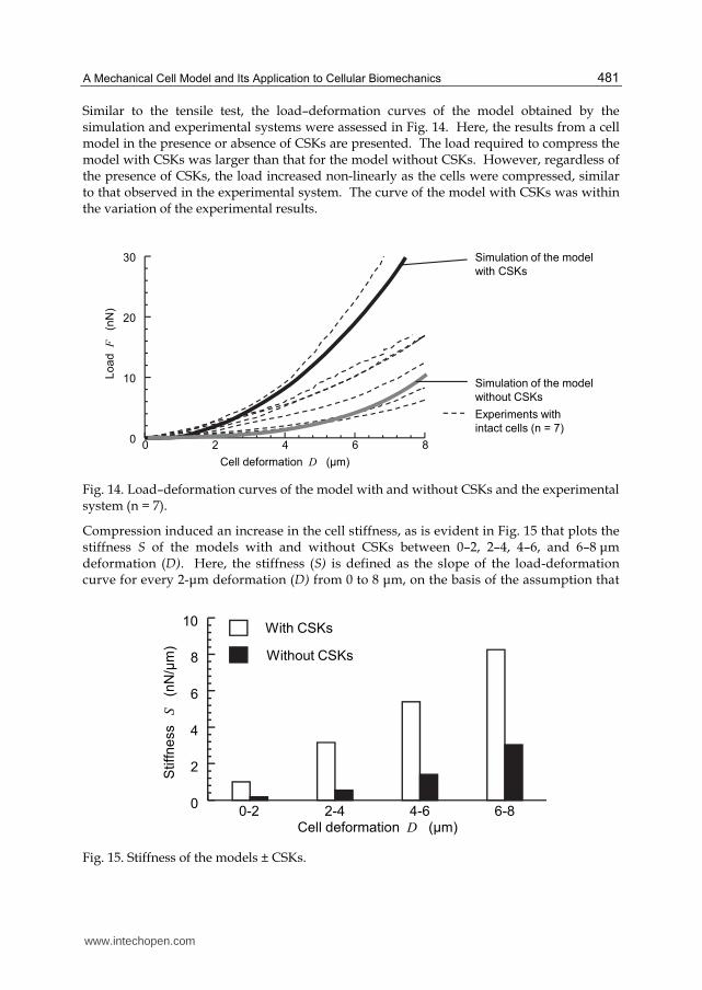
Similar to the tensile test, the load–deformation curves of the model obtained by the simulation and experimental systems were assessed in Fig. 14. Here, the results from a cell model in the presence or absence of CSKs are presented. The load required to compress the model with CSKs was larger than that for the model without CSKs. However, regardless of the presence of CSKs, the load increased non-linearly as the cells were compressed, similar to that observed in the experimental system. The curve of the model with CSKs was within the variation of the experimental results.
0 2 4 6 80
10
20
30
Cell deformation D (μm)
Loa
d
F(n
N)
Experiments with
intact cells (n = 7)
Simulation of the model
with CSKs
Simulation of the model
without CSKs
Fig. 14. Load–deformation curves of the model with and without CSKs and the experimental system (n = 7).
Compression induced an increase in the cell stiffness, as is evident in Fig. 15 that plots the stiffness S of the models with and without CSKs between 0–2, 2–4, 4–6, and 6–8 μm deformation (D). Here, the stiffness (S) is defined as the slope of the load-deformation curve for every 2-μm deformation (D) from 0 to 8 μm, on the basis of the assumption that
Stiff
ne
ss
S(n
N/μ
m)
Cell deformation D (μm)0-2 2-4 4-6 6-8
0
2
4
6
8
10With CSKs
Without CSKs
Fig. 15. Stiffness of the models ± CSKs.
www.intechopen.com

Biomedical Engineering – From Theory to Applications
482
the curve is piecewise linear. Regardless of the presence of the CSKs, the stiffness was markedly elevated during cell compression. The stiffness of the model with the CSKs at an interval of 2 μm was larger than that of the model without CSKs. Such an increase in cell stiffness correlated with the elevation of the mean orientation angle θ of all CSKs. Figure 16(a) shows that the mean θ elevated with cell deformation, indicating that the CSKs were passively oriented perpendicularly to the compressed direction. Concomitantly, the CSKs that were vertical were stretched as a result of the vertical elongation of the cell. Consequently, the CSKs exerted a contractile force and gave rise to an increase in the resistance against the vertical elongation of the cell. This increase in resistance is reflected in the elevation of the stiffness of the whole cell. With the progress of compression, a larger number of CSKs were inclined in the vertical direction, causing a gradual increase in the cell stiffness. In support of this, a positive relationship between the mean orientation angle of the CSKs and the cell stiffness during cell compression is illustrated in Fig. 16(b).
0 2 4 6 842
44
46
48
50
52
Me
an
of
CS
K o
rien
tation
ang
le
θ(d
eg
)
Cell deformation D (μm)
Stiff
ne
ss
S(n
N/μ
m)
42 44 46 48 500
2
4
6
8
10
Mean of AF orientation angle θ (deg)
(a) (b)
Fig. 16. Plot of (a) the mean orientation angle θ of CSKs against the cell deformation D, and (b) the stiffness against the mean CSK orientation angle θ.
4.3 Discussion and summary
In this section, the mechano-cell model was used in a compression test. The results
addressed the significant contribution of the CSKs to the global compressive properties of a
cell. The passive reorientation of CSKs in a direction perpendicular to the compression gave
rise to an increase in the elastic resistance against the vertical elongation of the cell, thereby
increasing the stiffness of the entire cell against the compression.
5. Other applications of the mechano-cell model
In addition to the tensile and compressive tests, the mechano-cell model is capable of expressing the cell behaviour in mechanical tests to examine the local mechanical properties of a cell, including micropipette aspiration and atomic force microscopy, as exemplified in Figs. 17(a) and (b). Moreover, the model can simulate the behaviour of an
www.intechopen.com

A Mechanical Cell Model and Its Application to Cellular Biomechanics
483
adherent cell on a substrate (Fig. 17(c)). Such a simulation may be useful in grasping the mechanical status of a cell during culture under mechanical loads, such as cyclic stretch of the substrate. Further applications of the mechano-cell model are illustrated in Fig. 17(d) where the mechano-cell model was embedded in a tissue. Here, tissue behavior was described with continuum mechanics under the assumption of an isotropic linear elastic material, and the behaviours of the CSKs within a cell upon the stretch of a tissue were examined. The combined use of the mechano-cell model with the continuum model will help achieve structural integration across the physical scales of biomechanical organization from CSKs to tissue.
(a) Micropipette
aspiration
(c) Substrate
stretch
(b) Nano indentation
Tissue Cell Cytoskeleton
(d) Analysis of mechanical behaviors of cell and cytoskeleton in tissue
Fig. 17. Applications of the mechano-cell model.
6. Summary
In this study, we aimed to develop a cell model that mechanically describes cellular
behaviour as an assembly of subcellular components, and its applications in exploring the
relationship between the mechanics of the subcellular components and the global
mechanical properties of a cell. The model revealed how subcellular components alter their
structure during cell deformation and demonstrated how such changes reflect the
mechanical properties of the cell. The model provided a physical interpretation of the
relationships between cellular deformation, the mechanical properties of a cell, and the
mechanical behaviour of the subcellular components.
A deep understanding of the mechanical characteristics of the subcellular components
will offer valuable insight into the structure-function paradigm. However, it is hindered
by the complex and heterogeneous structures of the subcellular components. Despite the
recent advances in imaging techniques, the visualization methods of the structural
changes in the CSKs of living cells during mechanical tests have not been well established.
Furthermore, it is challenging to quantify the contribution of individual subcellular
components to the overall mechanical response of a cell, solely from experimental data.
The mechano-cell model is expected to help overcome these experimental drawbacks.
www.intechopen.com

Biomedical Engineering – From Theory to Applications
484
The results described here address the use of the mechano-cell model in aiding our
understanding of the behaviour of heterogeneous intracellular structures and the cell as a
whole.
7. Acknowledgment
This work was supported in part by a Grant-in-Aid for JSPS Fellows (21�1007) from the
Japan Society for the Promotion of Science (JSPS) and “The Next-Generation Integrated
Simulation of Living Matter”, part of the Development and Use of the Next-Generation
Supercomputer Project of the Ministry of Education, Culture, Sports, Science and
Technology (MEXT). We thank Dr. Hiroshi Miyazaki, Dr. Kenichiro Koshiyama and Mr.
Ray Noguchi for their useful comments on this work.
8. References
Boey, S.K.; Boal, D.H. & Discher, D.E. (1998). Simulations of the Erythrocyte Cytoskeleton at
Large Deformation. I. Microscopic Models. Biophysical Journal, Vol.75, No.3,
(September, 1998), pp. 1573-1583, ISSN 0006-3495
Cohen, C. R.; Mills, I. Du, W. Kamal, K. & Sumpio B. E. (1997). Activation of the Adenylyl
Cyclase/Cyclic AMP/Protein Kinase A Pathway in Endothelial Cells Exposed to
Cyclic Strain. Experimental Cell Research, Vol.231, No.1, (February, 1997), pp. 184-
189, ISSN 0013-4827
Deguchi, S.; Ohashi, T. & Sato, M. (2005). Evaluation of Tension in Actin Bundle of
Endothelial Cells Based on Preexisting Strain and Tensile Properties Measurements.
Molecular and Cellular Biomechanics, Vol.2, No.3, (September, 2005), pp. 125-133,
ISSN 1556-5297
Feneberg, W.; Aepfelbacher, M. & Sackmann, E. (2004). Microviscoelasticity of the Apical
Cell Surface of Human Umbilical Vein Endothelial Cells (HUVEC) within
Confluent Monolayers. Biophysical Journal, Vol.87, No.2, (August, 2004), pp. 1338-
1350, ISSN 0006-3495
Haga, H.; Nagayama, M. Kawabata, K. Ito, E. Ushiki, T. & Sambongi, T. (2000). Time-
lapse Viscoelastic Imaging of Living Fibroblasts Using Force Modulation Mode
in AFM. Journal of Electron Microscopy, Vol.49, No.3, pp. 473-481, ISSN 0022-
0744
Ingber, D.E. (2003). Tensegrity II. How Structural Networks Influence Cellular Information
Processing Networks. Journal of Cell Science, Vol.116, No.8, (April, 2003), pp. 1397-
1408, ISSN 0021-9533
Karcher, H.; Lammerding, J. Huang, H. Lee, R.T. Kamm, R.D. & Kaazempur-Mofrad MR.
(2003). A Three-dimensional Viscoelastic Model for Cell Deformation with
Experimental Verification. Biophysical Journal, Vol.85, No.5, (November, 2003), pp.
3336-3349, ISSN 0006-3495.
Li, J.; Dao, M. Lim, C.T. & Suresh, S. (2005). Spectrin-level Modeling of the Cytoskeleton and
Optical Tweezers Stretching of the Erythrocyte. Biophysical Journal, Vol.88, No.5,
(May, 2005), pp. 3707-3719, ISSN 0006-3495
www.intechopen.com

A Mechanical Cell Model and Its Application to Cellular Biomechanics
485
Mahaffy, R.E.; Park, S. Gerde, E. Kas, J. & Shih, C.K. (2004). Quantitative Analysis of the
Viscoelastic Properties of Thin Regions of Fibroblasts Using Atomic Force
Microscopy. Biophysical Journal, Vol.86, No.3, (March, 2004), pp. 1777-1793, ISSN
0006-3495
McGarry, J.G. & Prendergast, P.J. (2004). A Three-dimensional Finite Element Model of an
Adherent Eukaryotic Cell. European Cells and Materials, Vol.7, (April, 2004), pp. 27-
33, ISSN 1473-2262
Miyazaki, H.; Hasegawa, Y. & Hayashi, K. (2000). A Newly Designed Tensile Tester for Cells
and Its Application to Fibroblasts. Journal of Biomechanics, Vol.33, No.1, (January,
1999), pp. 97-104, ISSN 0021-9290
Mohandas, N. & Evans, E. (1994). Mechanical Properties of the Red Cell Membrane in
Relation to Molecular Structure and Genetic Defects. Annual Review of Biophysics and
Biomolecular Structure, Vol.23, pp. 787-818, ISSN 1056-8700
Nagayama, K.; Nagano, Y. Sato, M. & Matsumoto, T. (2006). Effect of Actin Filament
Distribution on Tensile Properties of Smooth Muscle Cells Obtained From Rat
Thoracic Aortas. Journal of Biomechanics, Vol.39, No.2, pp. 293-301, ISSN 0021-
9290
Satcher, R.L. Jr. & Dewey, C.F. Jr. (1996). Theoretical Estimates of Mechanical Properties of
the Endothelial Cell Cytoskeleton. Biophysical Journal, Vol.71, No.1, (July, 1996), pp.
109-118, ISSN 0006-3495
Shieh, A.C. & Athanasiou, K.A. (2007). Dynamic Compression of Single Cells. Osteoarthritis
Cartilage, Vol.15, No.3, (March, 2007), pp. 328-334, ISSN 1063-4584
Stamenović, D.; Fredberg, J.J. Wang, N. Butler, J.P. & Ingber, D.E. (1996) A
Microstructural Approach to Cytoskeletal Mechanics Based on Tensegrity.
Journal of Theoretical Biology, Vol.181, No.2, (July, 1996), pp. 125-136, ISSN 0022-
5193
Titushkin, I. & Cho, M. (2007). Modulation of Cellular Mechanics during Osteogenic
Differentiation of Human Mesenchymal Stem Cells. Biophysical Journal, Vol.93,
No.10, (November, 2007), pp. 3693-3702, ISSN 0006-3495
Ujihara, Y.; Nakamura, M. Miyazaki, H. & Wada, S. (2010a). Proposed Spring Network Cell
Model Based on a Minimum Energy Concept, Annals of Biomedical Engineering,
Vol.38, No.4, (April, 2010), pp. 1530-1538, ISSN 0090-6964
Ujihara, Y.; Nakamura, M. Miyazaki, H. & Wada, S. (2010b).Effects of Actin Filaments on the
Compressive Properties of a whole cell, 6th World Congress of Biomechanics Abstract,
pp. 478, Singapore, August 1-6, 2010
Vaziri, A. & Mofrad, M.R. (2007). Mechanics and Deformation of the Nucleus in
Micropipette Aspiration Experiment. Journal of Biomechanics, Vol.40, No.9, pp. 2053-
2062, ISSN 0021-9290
Wada, S. & Kobayashi, R. (2003) Numerical simulation of various shape changes of a
swollen red blood cell by decrease of its volume. Transactions of the Japan Society of
Mechanical Engineers A, Vol.69, No.677, (January, 2003), pp. 14-21, ISSN 0387-5008,
(in Japanese)
Wang, N. (1998) Mechanical Interactions among Cytoskeletal Filaments. Hypertension,
Vol.32, No.1, (July, 1998), pp. 162-165, ISSN 0194-911X
www.intechopen.com

Biomedical Engineering – From Theory to Applications
486
Zhelev, D.V.; Needham, D. & Hochmuth, R.M. (1994). Role of the Membrane Cortex in
Neutrophil Deformation in Small Pipets. Biophysical Journal, Vol.67, No.2, (August,
1994), pp. 696-705, ISSN 0006-3495
www.intechopen.com

Biomedical Engineering - From Theory to ApplicationsEdited by Prof. Reza Fazel
ISBN 978-953-307-637-9Hard cover, 486 pagesPublisher InTechPublished online 29, August, 2011Published in print edition August, 2011
InTech EuropeUniversity Campus STeP Ri Slavka Krautzeka 83/A 51000 Rijeka, Croatia Phone: +385 (51) 770 447 Fax: +385 (51) 686 166www.intechopen.com
InTech ChinaUnit 405, Office Block, Hotel Equatorial Shanghai No.65, Yan An Road (West), Shanghai, 200040, China
Phone: +86-21-62489820 Fax: +86-21-62489821
In all different areas in biomedical engineering, the ultimate objectives in research and education are toimprove the quality life, reduce the impact of disease on the everyday life of individuals, and provide anappropriate infrastructure to promote and enhance the interaction of biomedical engineering researchers. Thisbook is prepared in two volumes to introduce a recent advances in different areas of biomedical engineeringsuch as biomaterials, cellular engineering, biomedical devices, nanotechnology, and biomechanics. It is hopedthat both of the volumes will bring more awareness about the biomedical engineering field and help incompleting or establishing new research areas in biomedical engineering.
How to referenceIn order to correctly reference this scholarly work, feel free to copy and paste the following:
Yoshihiro Ujihara, Masanori Nakamura and Shigeo Wada (2011). A Mechanical Cell Model and Its Applicationto Cellular Biomechanics, Biomedical Engineering - From Theory to Applications, Prof. Reza Fazel (Ed.), ISBN:978-953-307-637-9, InTech, Available from: http://www.intechopen.com/books/biomedical-engineering-from-theory-to-applications/a-mechanical-cell-model-and-its-application-to-cellular-biomechanics