a master class on wood lateral-resisting systems
TRANSCRIPT
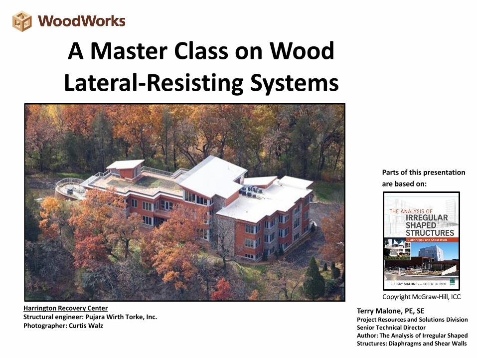
A Master Class on Wood Lateral-Resisting Systems
Terry Malone, PE, SEProject Resources and Solutions DivisionSenior Technical DirectorAuthor: The Analysis of Irregular Shaped Structures: Diaphragms and Shear Walls
Copyright McGraw-Hill, ICC
Parts of this presentation
are based on:
Harrington Recovery CenterStructural engineer: Pujara Wirth Torke, Inc.Photographer: Curtis Walz
“The Wood Products Council” is a Registered Provider with The American Institute of Architects Continuing Education Systems (AIA/CES), Provider #G516.
Credit(s) earned on completion of this course will be reported to AIA CES for AIA members. Certificates of Completion for both AIA members and non-AIA members are available upon request.
This course is registered with AIA CES for continuing professional education. As such, it does not include content that may be deemed or construed to be an approval or endorsement by the AIA of any material of construction or any method or manner ofhandling, using, distributing, or dealing in any material or product.
__________________________________
Questions related to specific materials, methods, and services will be addressed at the conclusion of this presentation.
Course Description
Creative structures are becoming increasingly common. Their
aesthetically pleasing shapes create new demands and challenges
on finding engineering solutions.
This presentation will provide the necessary analytical tools to solve
complex lateral load paths across areas of discontinuities in
irregular shaped diaphragms. A complete lateral plan review will be
conducted on a two-story hotel to see how these design tools can
be applied.
Learning Objectives
• Answer some of the more commonly asked
questions regarding complex diaphragm design.
• Review the analysis methods available to transfer
shear forces across areas of discontinuities.
• Examine the important role of collectors for
distributing forces through the diaphragm.
• Provide a comprehensive lateral Plan Review of a
complex diaphragm.
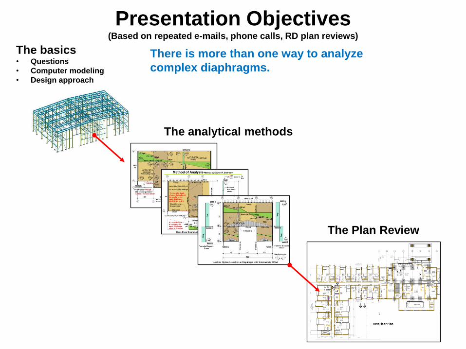
Presentation Objectives(Based on repeated e-mails, phone calls, RD plan reviews)
The basics• Questions
• Computer modeling
• Design approach
The analytical methods
The Plan Review
There is more than one way to analyze
complex diaphragms.
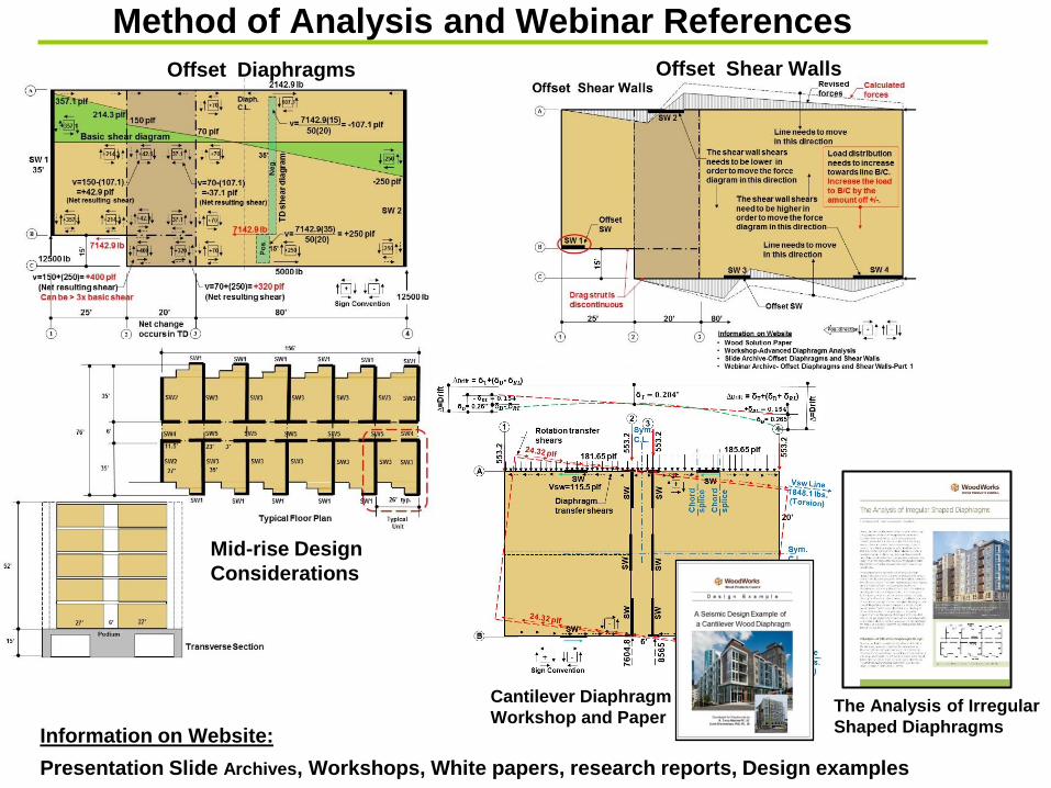
Cantilever Diaphragm
Workshop and Paper
Method of Analysis and Webinar References
Offset Shear WallsOffset Diaphragms
Presentation Slide Archives, Workshops, White papers, research reports, Design examples
Information on Website:
Mid-rise Design
Considerations
The Analysis of Irregular
Shaped Diaphragms
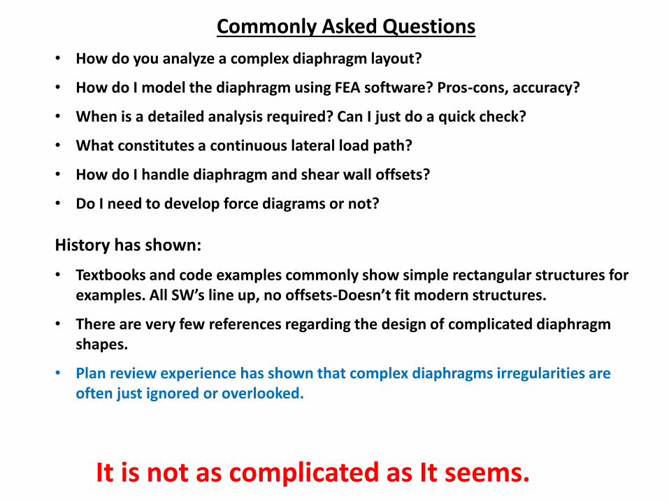
Commonly Asked Questions
• How do you analyze a complex diaphragm layout?
• How do I model the diaphragm using FEA software? Pros-cons, accuracy?
• When is a detailed analysis required? Can I just do a quick check?
• What constitutes a continuous lateral load path?
• How do I handle diaphragm and shear wall offsets?
• Do I need to develop force diagrams or not?
History has shown:
• Textbooks and code examples commonly show simple rectangular structures for examples. All SW’s line up, no offsets-Doesn’t fit modern structures.
• There are very few references regarding the design of complicated diaphragm shapes.
• Plan review experience has shown that complex diaphragms irregularities are often just ignored or overlooked.
It is not as complicated as It seems.
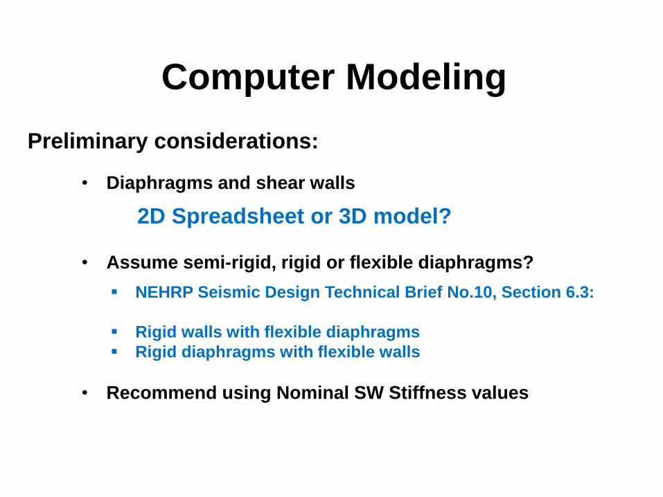
Preliminary considerations:
• Diaphragms and shear walls
2D Spreadsheet or 3D model?
• Assume semi-rigid, rigid or flexible diaphragms?
▪ NEHRP Seismic Design Technical Brief No.10, Section 6.3:
▪ Rigid walls with flexible diaphragms
▪ Rigid diaphragms with flexible walls
• Recommend using Nominal SW Stiffness values
Computer Modeling
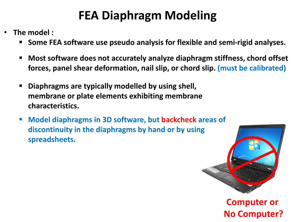
Computer or No Computer?
FEA Diaphragm Modeling• The model :
▪ Some FEA software use pseudo analysis for flexible and semi-rigid analyses.
▪ Most software does not accurately analyze diaphragm stiffness, chord offset forces, panel shear deformation, nail slip, or chord slip. (must be calibrated)
▪ Diaphragms are typically modelled by using shell, membrane or plate elements exhibiting membrane characteristics.
▪ Model diaphragms in 3D software, but backcheck areas of discontinuity in the diaphragms by hand or by using spreadsheets.
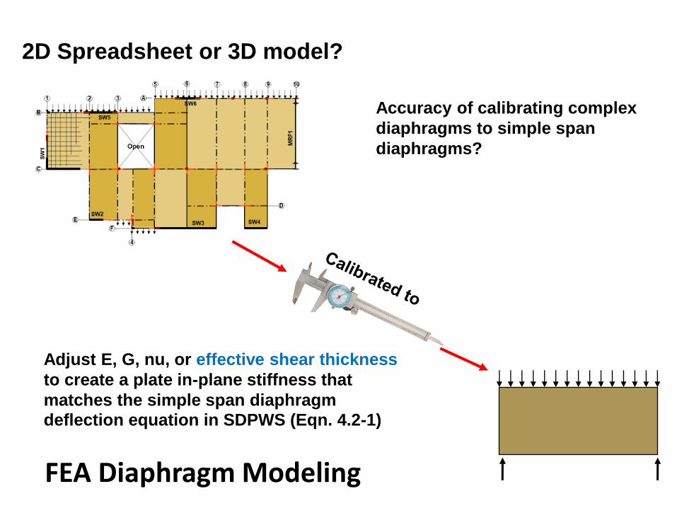
FEA Diaphragm Modeling
Adjust E, G, nu, or effective shear thickness
to create a plate in-plane stiffness that
matches the simple span diaphragm
deflection equation in SDPWS (Eqn. 4.2-1)
Accuracy of calibrating complex
diaphragms to simple span
diaphragms?
2D Spreadsheet or 3D model?
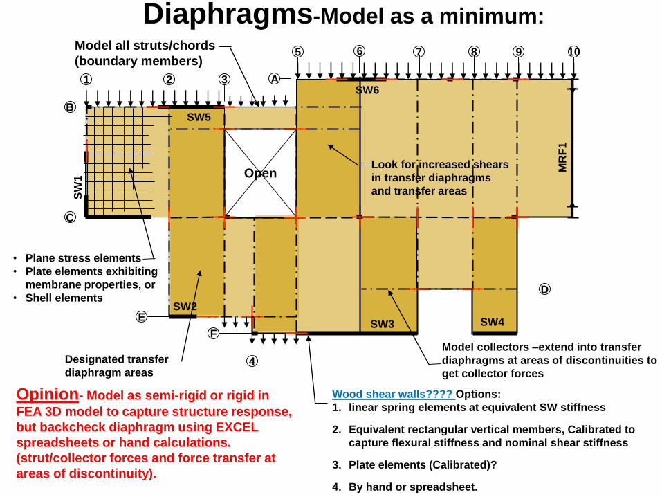
Model all struts/chords
(boundary members)
Open
3
4
5
21
F
E
D
C
B
6 9 107 8
Look for increased shears
in transfer diaphragms
and transfer areas
Model collectors –extend into transfer
diaphragms at areas of discontinuities to
get collector forces
SW
1
SW5
SW2
SW3
SW6
SW4
MR
F1
A
• Plane stress elements
• Plate elements exhibiting
membrane properties, or
• Shell elements
Designated transfer
diaphragm areas
Wood shear walls???? Options:
1. linear spring elements at equivalent SW stiffness
2. Equivalent rectangular vertical members, Calibrated to
capture flexural stiffness and nominal shear stiffness
3. Plate elements (Calibrated)?
4. By hand or spreadsheet.
Opinion- Model as semi-rigid or rigid in
FEA 3D model to capture structure response,
but backcheck diaphragm using EXCEL
spreadsheets or hand calculations.
(strut/collector forces and force transfer at
areas of discontinuity).
Diaphragms-Model as a minimum:
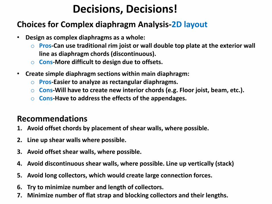
Decisions, Decisions!Choices for Complex diaphragm Analysis-2D layout
• Design as complex diaphragms as a whole:o Pros-Can use traditional rim joist or wall double top plate at the exterior wall
line as diaphragm chords (discontinuous).o Cons-More difficult to design due to offsets.
• Create simple diaphragm sections within main diaphragm:o Pros-Easier to analyze as rectangular diaphragms.o Cons-Will have to create new interior chords (e.g. Floor joist, beam, etc.).o Cons-Have to address the effects of the appendages.
Recommendations1. Avoid offset chords by placement of shear walls, where possible.
2. Line up shear walls where possible.
3. Avoid offset shear walls, where possible.
4. Avoid discontinuous shear walls, where possible. Line up vertically (stack)
5. Avoid long collectors, which would create large connection forces.
6. Try to minimize number and length of collectors.7. Minimize number of flat strap and blocking collectors and their lengths.
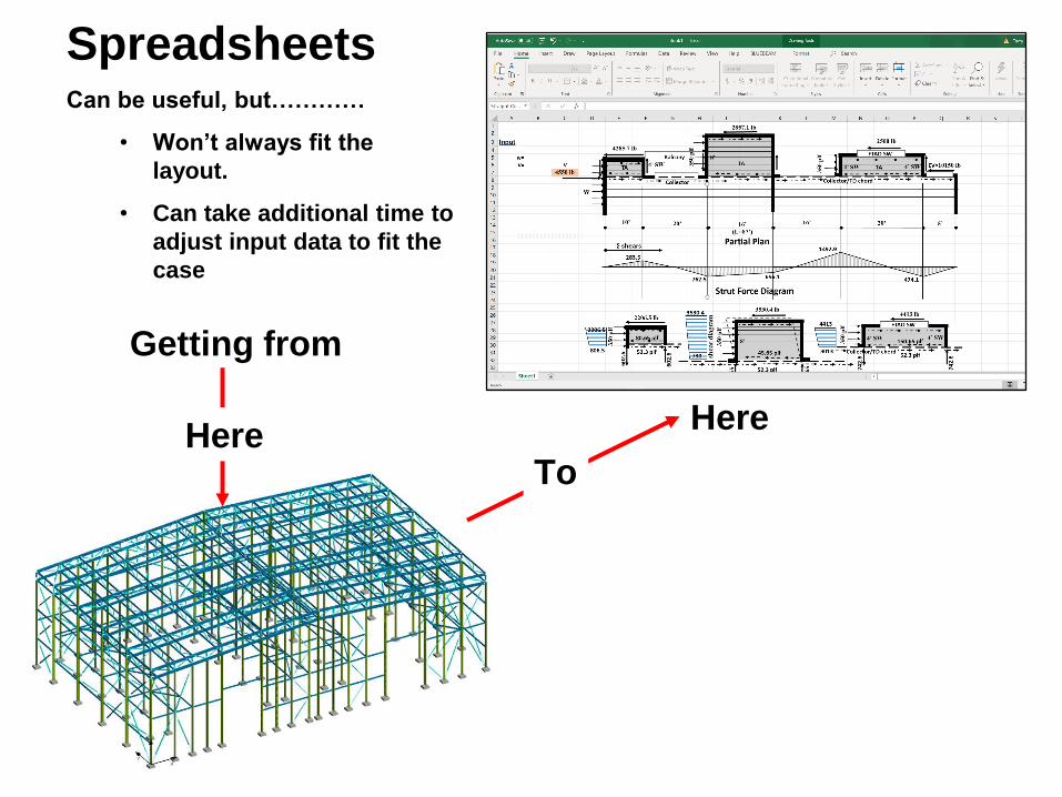
SpreadsheetsCan be useful, but…………
• Won’t always fit the
layout.
• Can take additional time to
adjust input data to fit the
case
Getting from
HereHere
To
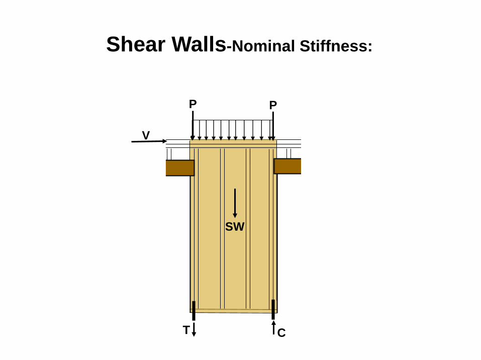
SW
T C
P
V
P
Shear Walls-Nominal Stiffness:
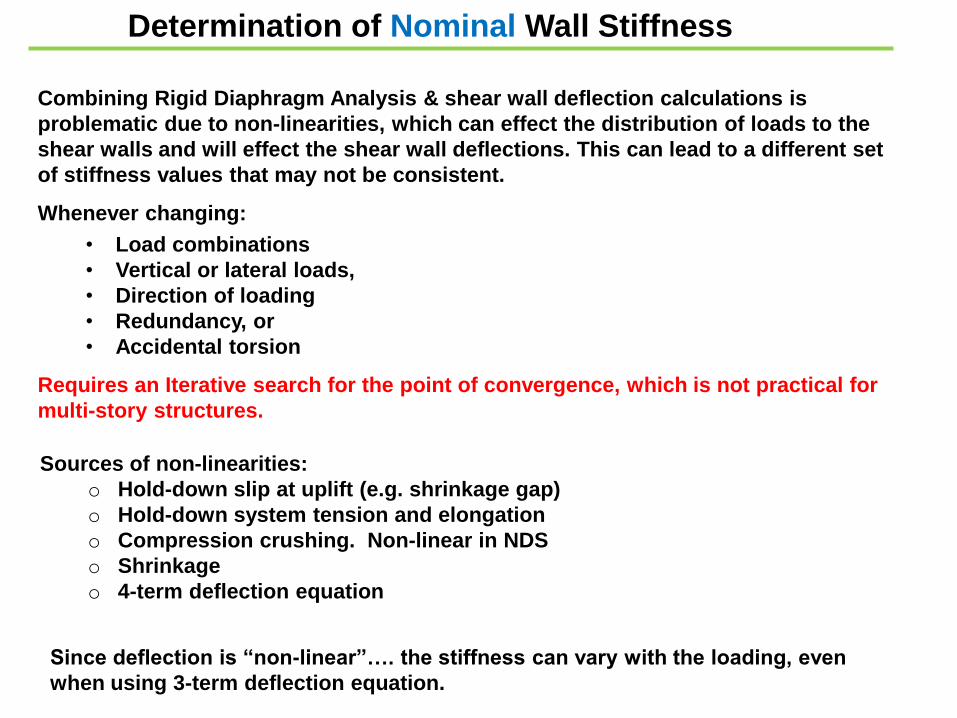
Combining Rigid Diaphragm Analysis & shear wall deflection calculations is
problematic due to non-linearities, which can effect the distribution of loads to the
shear walls and will effect the shear wall deflections. This can lead to a different set
of stiffness values that may not be consistent.
Whenever changing:
Sources of non-linearities:
o Hold-down slip at uplift (e.g. shrinkage gap)
o Hold-down system tension and elongation
o Compression crushing. Non-linear in NDS
o Shrinkage
o 4-term deflection equation
• Load combinations
• Vertical or lateral loads,
• Direction of loading
• Redundancy, or
• Accidental torsion
Requires an Iterative search for the point of convergence, which is not practical for
multi-story structures.
Determination of Nominal Wall Stiffness
Since deflection is “non-linear”…. the stiffness can vary with the loading, even
when using 3-term deflection equation.
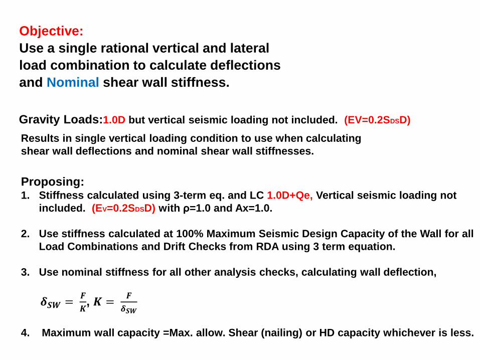
Gravity Loads:1.0D but vertical seismic loading not included. (EV=0.2SDSD)
Results in single vertical loading condition to use when calculating
shear wall deflections and nominal shear wall stiffnesses.
Objective:
Use a single rational vertical and lateral
load combination to calculate deflections
and Nominal shear wall stiffness.
Proposing:1. Stiffness calculated using 3-term eq. and LC 1.0D+Qe, Vertical seismic loading not
included. (EV=0.2SDSD) with ρ=1.0 and Ax=1.0.
2. Use stiffness calculated at 100% Maximum Seismic Design Capacity of the Wall for all
Load Combinations and Drift Checks from RDA using 3 term equation.
3. Use nominal stiffness for all other analysis checks, calculating wall deflection,
𝜹𝑺𝑾 =𝑭
𝑲, 𝑲 =
𝑭
𝜹𝑺𝑾
4. Maximum wall capacity =Max. allow. Shear (nailing) or HD capacity whichever is less.
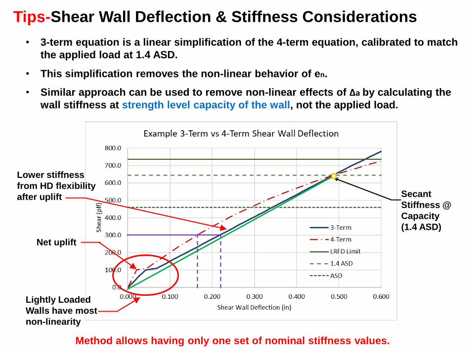
Tips-Shear Wall Deflection & Stiffness Considerations
Secant
Stiffness @
Capacity
(1.4 ASD)
Net uplift
Lower stiffness
from HD flexibility
after uplift
Lightly Loaded
Walls have most
non-linearity
Method allows having only one set of nominal stiffness values.
• 3-term equation is a linear simplification of the 4-term equation, calibrated to match
the applied load at 1.4 ASD.
• This simplification removes the non-linear behavior of en.
• Similar approach can be used to remove non-linear effects of ∆a by calculating the
wall stiffness at strength level capacity of the wall, not the applied load.
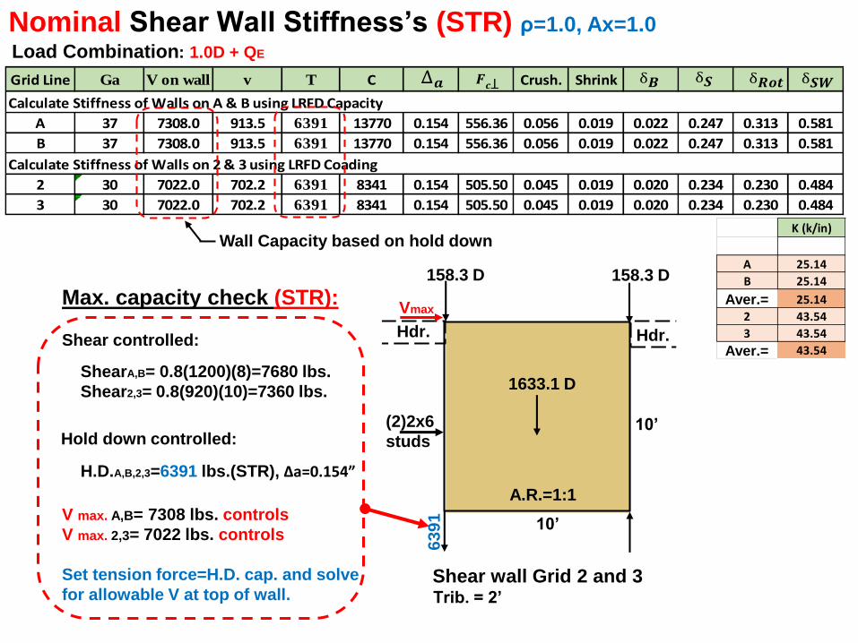
Nominal Shear Wall Stiffness’s (STR) ρ=1.0, Ax=1.0
Load Combination: 1.0D + QE
Aver.=
Aver.=
Shear wall Grid 2 and 3
10’
10’
A.R.=1:1
1633.1 D
158.3 D158.3 D
(2)2x6
studs
Hdr.Hdr.
Wall Capacity based on hold downK (k/in)
A 25.14
B 25.14
25.14
2 43.54
3 43.54
43.54
Grid Line Ga V on wall v T C Crush. Shrink
Calculate Stiffness of Walls on A & B using LRFD Capacity
A 37 7308.0 913.5 6391 13770 0.154 556.36 0.056 0.019 0.022 0.247 0.313 0.581
B 37 7308.0 913.5 6391 13770 0.154 556.36 0.056 0.019 0.022 0.247 0.313 0.581
Calculate Stiffness of Walls on 2 & 3 using LRFD Coading
2 30 7022.0 702.2 6391 8341 0.154 505.50 0.045 0.019 0.020 0.234 0.230 0.484
3 30 7022.0 702.2 6391 8341 0.154 505.50 0.045 0.019 0.020 0.234 0.230 0.484
𝑺𝑾 𝑺 𝑭
Trib. = 2’
Vmax
6391
Max. capacity check (STR):
Shear controlled:
ShearA,B= 0.8(1200)(8)=7680 lbs.
Shear2,3= 0.8(920)(10)=7360 lbs.
H.D.A,B,2,3=6391 lbs.(STR), ∆a=0.154”
V max. A,B= 7308 lbs. controls
V max. 2,3= 7022 lbs. controls
Set tension force=H.D. cap. and solve
for allowable V at top of wall.
Hold down controlled:
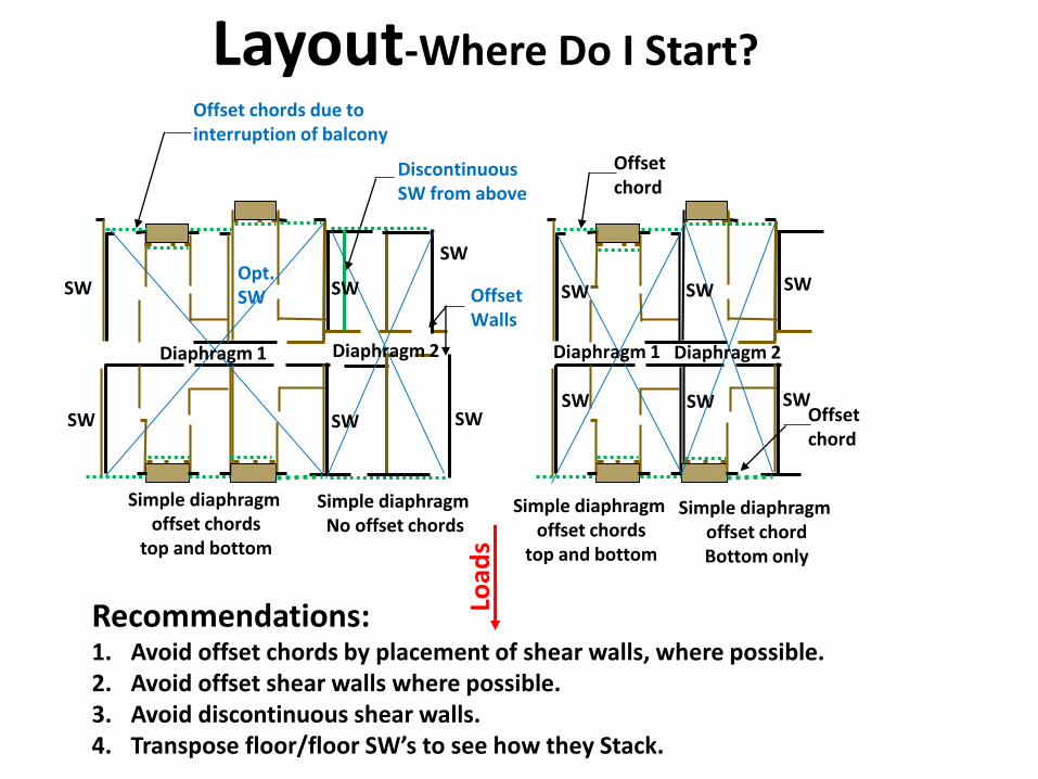
Layout-Where Do I Start?
Offset Walls
Offset chords due to interruption of balcony
Offset chord
Simple diaphragm offset chords
top and bottom
Simple diaphragm No offset chords
Offset chord
Simple diaphragm offset chords
top and bottom
Simple diaphragm offset chordBottom only
SW SW
SWSWSW
SW
SW
SW
SW
SW
Discontinuous SW from above
Diaphragm 1 Diaphragm 2Diaphragm 1 Diaphragm 2
Load
s
Recommendations:1. Avoid offset chords by placement of shear walls, where possible.2. Avoid offset shear walls where possible.3. Avoid discontinuous shear walls.4. Transpose floor/floor SW’s to see how they Stack.
SW
SW
Opt.SW
26’
76’ 66’
25’ 40’
120’
20’
W=400 plf
W=400 plf
Flexible
Semi-rigidRigid
16’10’
16’
4’
10’
4’533 #
16,000 # 15’
53
3 #
53
3 #
533 #
Nai
ling
to
dev
elo
p
forc
e in
to
tru
ss
Nai
ling
for
tru
ss t
o
de
velo
p f
orc
e f
ull
dep
th o
f d
iap
hra
gm
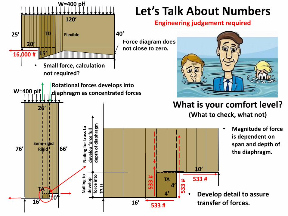
Let’s Talk About NumbersEngineering judgement required
TD
TA
What is your comfort level?(What to check, what not)
• Magnitude of force is dependent on span and depth of the diaphragm.
Rotational forces develops into diaphragm as concentrated forces
TA
Force diagram does
not close to zero.
• Small force, calculation not required?
• Develop detail to assure transfer of forces.
L= 150.0 ft.
w= 200.0 plf
L1= 20.0 ft.
L2= 20.0 ft. Sum O.K.
L3= 10.0 ft. <=L/2 500.0 100.0 155.6 155.6 230.8
L4= 20.0 ft. F= 8653.8
H1= 30.0 ft. F= 8666.7 F= 11111.1
H2= 15.0 ft. F= 9777.8 2888.9 3418.8 533.3
H3= 20.0 ft.
- 170.9402 461.5
F= 8666.7 - 144.4
MB2= 260000.0 ft. lbs. A/R A/R
FB2= 8666.7 Lbs. 2.3 3.3
MC3= 500000.0 ft. lbs. F= 4333.3
FC3= 11111.1 Lbs.
Net Shears Above line B B F= 11111.1
V1= 500.0 plf F= 8000.0 8666.7
V2L= 366.7 plf
V2R= 100.0 plf 288.9
V3L= 11.1 plf RL= 15000.0
V3R= 155.6 plf 11111.1
+ 384.6154
Net Shears Below line B 5777.8
V2R= 533.3 plf F= 7692.3
V3L= 444.4 plf F= 9230.8 7692.3
V3R= 155.6 plf 500.0
Horizontal Members
Net Shears Above line C 366.7 F= 8653.8 F2A= 8666.7 Lbs.
V4L= 111.1 plf 244.4 F3A= 9777.8 Lbs.
V4R= -94.0 plf 155.6 RR= 15000.0 F4A= 11111.1 Lbs.
V5L= 155.6 plf 111.1 Fcl= 8653.8 Lbs.
V5R= 15.4 plf 76.9
15.4 F2B= 8666.7 Lbs.
Net Shears below line C F4C= 11111.1 Lbs.
V4R= 461.5 plf Vertical Membersbers
V5L= 400.0 plf F2B= 8000.0 Lbs.
V5R= 15.4 plf F3B= 4333.3 Lbs.
F4C= 9230.8 Lbs.
V6= 230.8 plf F5C= 7692.3 Lbs.
230.8
54
Input Data
Ouput Data
6
L1 L2
L4
H1
H2
+
-
C
321
B
A
w (plf)
Basic Shear Diagram (plf)
+
-
+ +
+
+
+ +
+ +
+
+
+
-+
Transfer
Diaphragm
TD1
See sheet 2 for
multiple shear
wall segments
+ -
Sign Convention
Sheathing Elements
+ +
+
+
+
+
+
+
+
+
Transfer
Diaphragm
TD2
+
+
+
+
+
L3
H3
D
Maximum Shears (plf) per Area
1. Cells highlighted in green require input.
2. Numbers (420) are net shears in
diaphragm.
3. Outputs (F=4500) are strut / chord forces.
4. "Maximum Shears per area " is the
required
diaphragm nailing per area shown.
5. Diaphragm deflections are not included in
this
analysis, but must be checked.
6. L1+L2+L3+L4 must<= Ldiaph./2+
_
-
+
-
Neg
Pos +
Double Offset Diaphragm-Transverse Direction
Instructions
+
TAF= 2687.5 F= -1312.5
Lsw1= 10.0 Lsw2= 0.0 Lsw3= 10.0 Lsw4= 40.0 Lsw5= 4.0 F= 3200.0
F= -1312.5 F= -4625.0 F= 2125.0 F= 0.0
Vnet= 268.8 Vnet= 268.8 Vnet= 268.8 Vnet= 268.8 Vnet= 268.8
Ltotal= 150.0 4687.5 0.0 4687.5 18750.0 1875.0 V= 30000.0 Lb
Lsw= 64.0
Vsw= 468.8 Vd= -200.0 F= -1312.5 F= 1375.0 F= 6125.0
Vd= 200.0 Summing
L1= 20.0 L2= 0.0 L3= 30.0 L4= 20.0 L5= 16.0
VL 10000.0 20000.0 VR VL 10000.0 20000.0 VR VL 10000.0 20000.0 VR
Summing Summing Summing Summing
F= -4411.8 L1= 20.0
Lsw1= 40.0
Vd= -220.6
Vnet= 318.9 Ltotal= 90.0
Lsw= 40.0
Vsw= 750.0 L1= 50.0 Ltotal= 136.0 Summing
Vd(left)= 111.1 Vd= -333.3 Lsw= 56.0
25000.0 Vd(rt.)= 222.2 Lsw1= 16.0 Vsw= 535.7
Vd(left)= 73.5
Vnet= 315.1 Vd(rt.)= 147.1 F=3560
F= 12755.1 8571.4 Legend
Lsw2= Length Input Required
Ltotal= 98.0 F= -16666.7 Diaphragm Shear to Wall
Lsw= 48.0 Input Required
Vsw= 625.0 Vd= -306.1 L1= 50.0 F= 630.3 Resulting Shear Force to
Vd(left)= 102.0 Vd= -220.6 L2= 40.0 Wall Section
Vd(rt.)= 204.1 F= -8193.3 F=3560 Resulting Strut Force
30000.0
21428.6
F= -2551.0 Vnet= 416.7 Lsw2= 40.0 Vnet= 315.1
Lsw1= 40.0
F= 0.0
5000.0 F= 0.0 F= 4411.8
Vd= -220.6 L3= 20.0
Lsw2= 8.0 Vnet= 318.9 F= 0.0
Strut/Collector Forces Exterior Shear Wall Lines
Interior Shear Wall Lines
Instructions:
1. Input wall lengths and distances between walls.
2. Input 0 if wall sections and
separations do not exist.
3. Input diaphragm reactions to wall lines.
Most of the commonly used layouts
have been presented for convenience.
Vd(right)
Vsw Vsw
Vd(net)
Vnet Vnet
Vd(net)
Vd(left)
Net Shears
Direct Shears
Strut Forces
Method
1
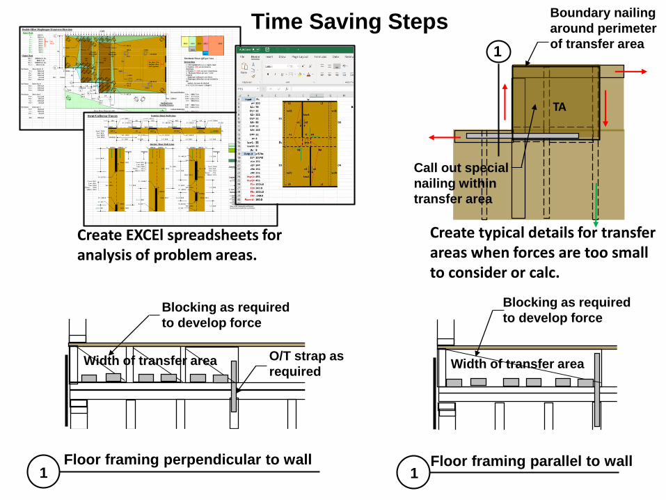
Floor framing perpendicular to wall Floor framing parallel to wall
Time Saving Steps
Blocking as required
to develop force
O/T strap as
required
1 1
1
Create EXCEl spreadsheets for analysis of problem areas.
Create typical details for transfer areas when forces are too small to consider or calc.
Blocking as required
to develop force
Width of transfer areaWidth of transfer area
Boundary nailing
around perimeter
of transfer area
Call out special
nailing within
transfer area
Q & A
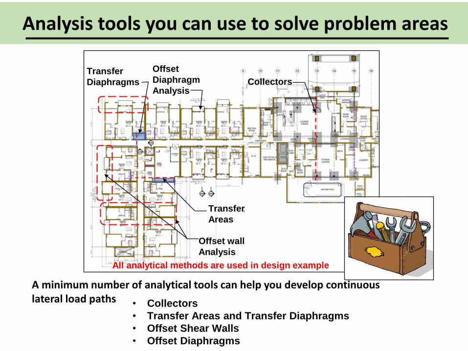
• Collectors
• Transfer Areas and Transfer Diaphragms
• Offset Shear Walls
• Offset Diaphragms
CollectorsTransfer
Diaphragms
Offset
Diaphragm
Analysis
Offset wall
Analysis
Transfer
Areas
All analytical methods are used in design example
Analysis tools you can use to solve problem areas
A minimum number of analytical tools can help you develop continuous lateral load paths
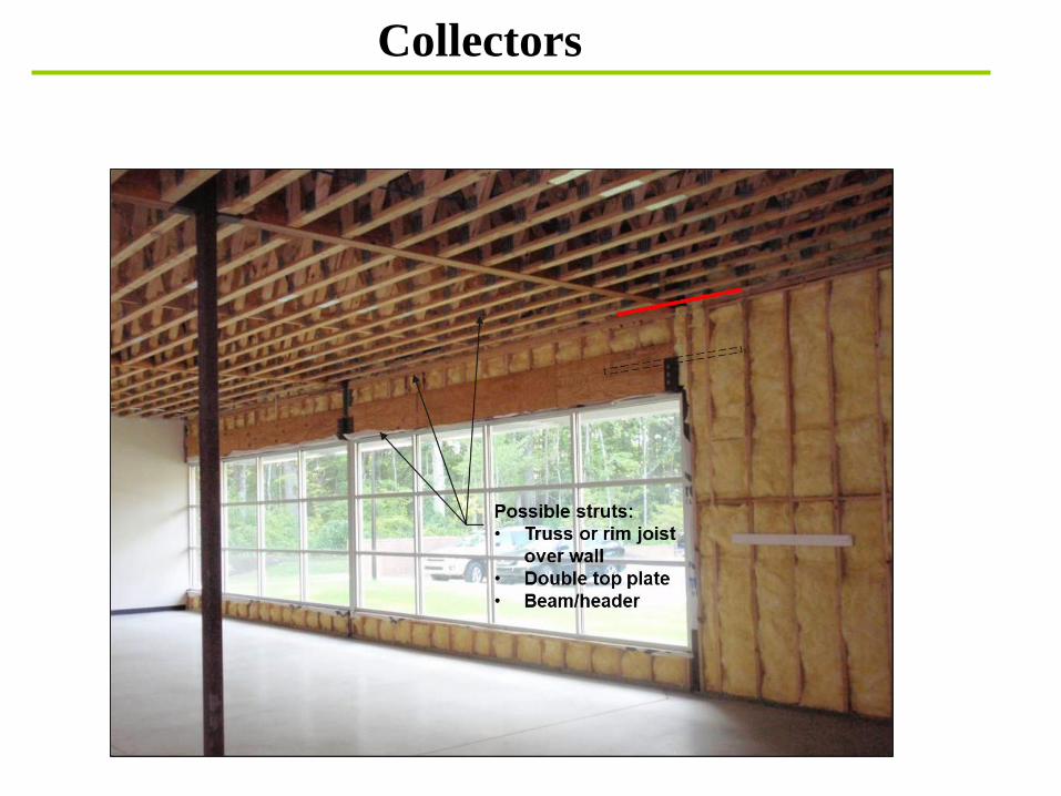
Collectors
Diaphragm 1 Diaphragm 2
Diaphragm 2
Boundary (typical)
Chord
Chord
Co
lle
cto
r
Str
ut
Str
ut
Chord
Str
ut
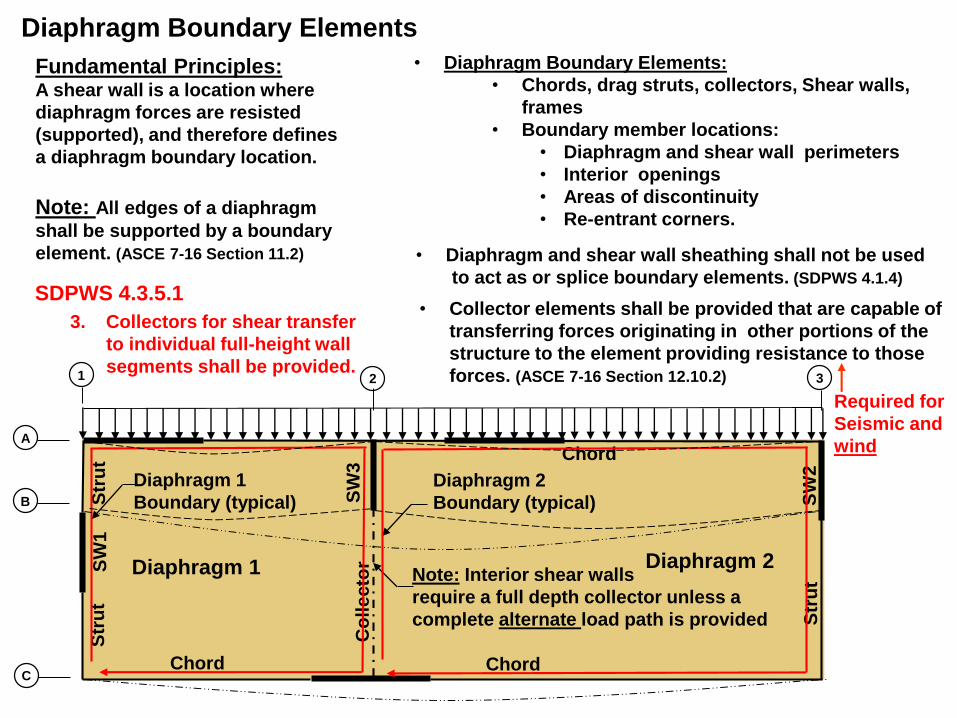
Fundamental Principles:A shear wall is a location where
diaphragm forces are resisted
(supported), and therefore defines
a diaphragm boundary location.
Note: Interior shear walls
require a full depth collector unless a
complete alternate load path is provided
Diaphragm Boundary Elements
SW
1
SW
2
SW
3
Note: All edges of a diaphragm
shall be supported by a boundary
element. (ASCE 7-16 Section 11.2)
Diaphragm 1
Boundary (typical)
• Diaphragm Boundary Elements:
• Chords, drag struts, collectors, Shear walls,
frames
• Boundary member locations:
• Diaphragm and shear wall perimeters
• Interior openings
• Areas of discontinuity
• Re-entrant corners.
• Diaphragm and shear wall sheathing shall not be used
to act as or splice boundary elements. (SDPWS 4.1.4)
• Collector elements shall be provided that are capable of
transferring forces originating in other portions of the
structure to the element providing resistance to those
forces. (ASCE 7-16 Section 12.10.2)
Required for
Seismic and
wind
1 2
B
3
C
A
3. Collectors for shear transfer
to individual full-height wall
segments shall be provided.
SDPWS 4.3.5.1
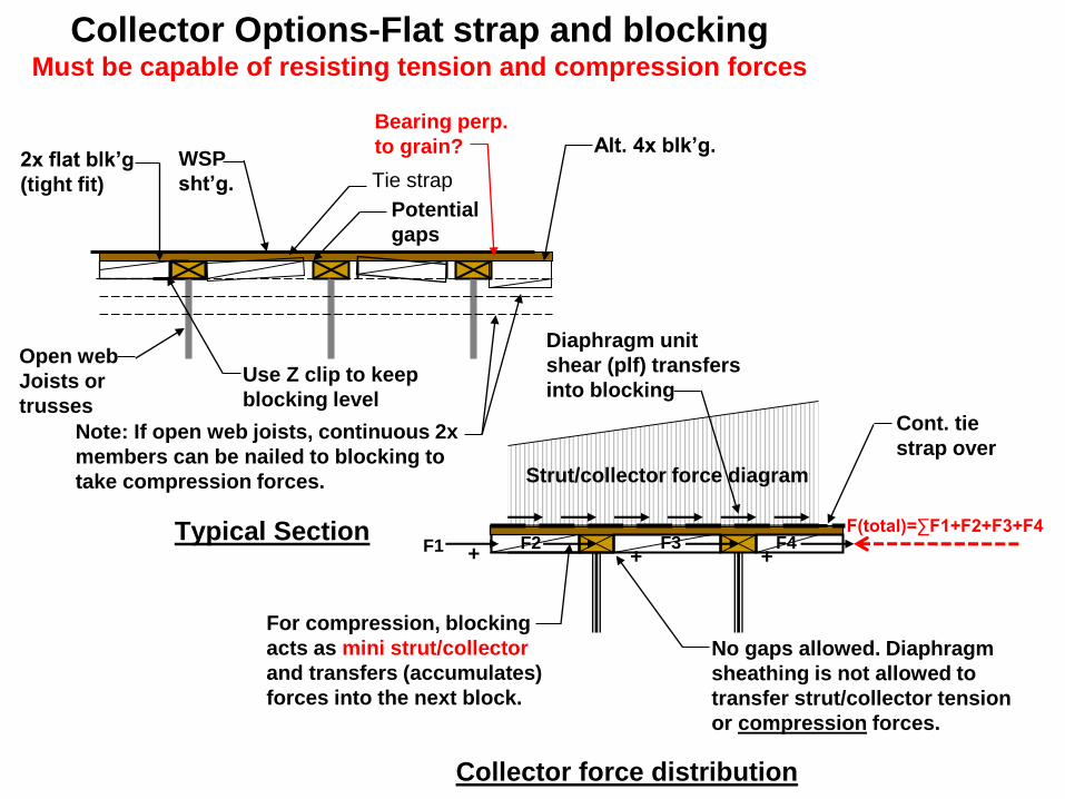
2x flat blk’g
(tight fit)
Potential
gaps
Typical Section
Note: If open web joists, continuous 2x
members can be nailed to blocking to
take compression forces.
Use Z clip to keep
blocking level
Bearing perp.
to grain? Alt. 4x blk’g.
Tie strapWSP
sht’g.
Open web
Joists or
trusses
Collector force distribution
Strut/collector force diagram
Diaphragm unit
shear (plf) transfers
into blocking
For compression, blocking
acts as mini strut/collector
and transfers (accumulates)
forces into the next block.
+ ++
No gaps allowed. Diaphragm
sheathing is not allowed to
transfer strut/collector tension
or compression forces.
F4F3F2F1
Cont. tie
strap over
F(total)=∑F1+F2+F3+F4
Collector Options-Flat strap and blockingMust be capable of resisting tension and compression forces
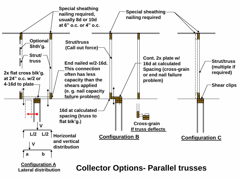
Special sheathing
nailing required
Strut/truss
(Call out force)
End nailed w/2-16d.
This connection
often has less
capacity than the
shears applied
(e. g. nail capacity
failure problem)
Cont. 2x plate w/
16d at calculated
Spacing (cross-grain
or end nail failure
problem)
16d at calculated
spacing (truss to
flat blk’g.)
Shear clips
Strut/truss
(multiple if
required)
Special sheathing
nailing required,
usually 8d or 10d
at 6” o.c. or 4” o.c.
Configuration A
Configuration CConfiguration B
Cross-grain
If truss deflects
Optional
Shth’g.
Strut/
truss
Lateral distribution
a b
V
V
L/2L/2
2x flat cross blk’g.
at 24” o.c. w/2 or
4-16d to plate
Horizontal
and vertical
distribution
Collector Options- Parallel trusses
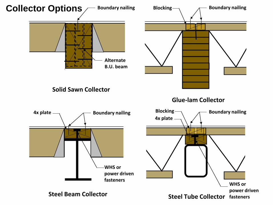
Solid Sawn Collector
Glue-lam Collector
Boundary nailing
Steel Beam Collector Steel Tube Collector
Boundary nailingBlocking
Boundary nailing4x plate Boundary nailing4x plate
Blocking
Alternate B.U. beam
WHS or power driven fasteners
WHS or power driven fasteners
Collector Options
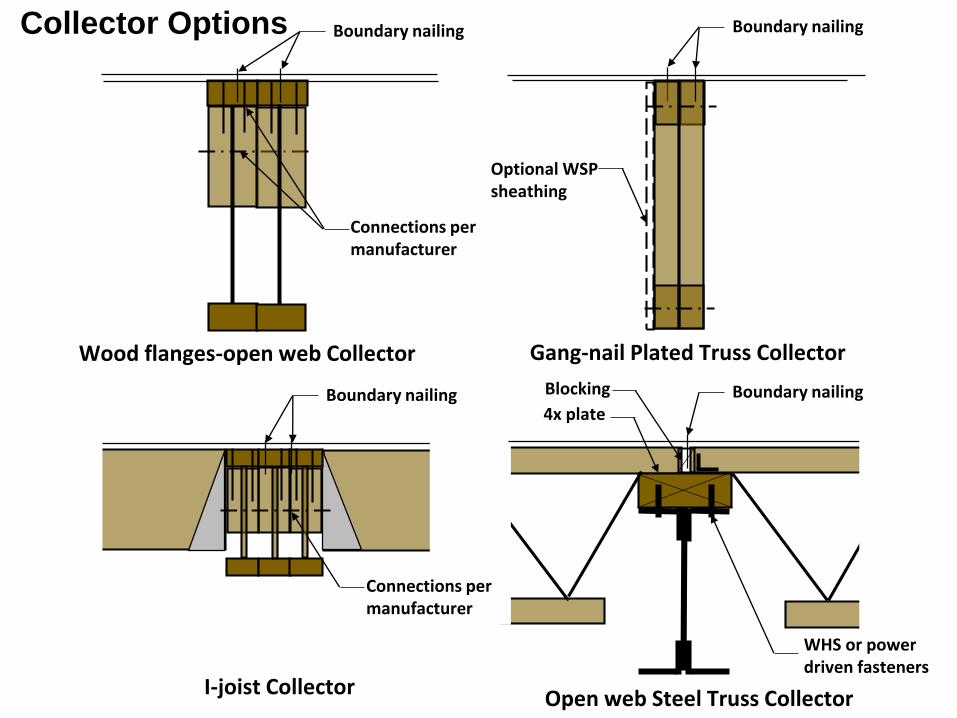
Wood flanges-open web Collector
Boundary nailing
I-joist Collector Open web Steel Truss Collector
Boundary nailing
Boundary nailing Boundary nailing4x plate
Blocking
Connections per manufacturer
Gang-nail Plated Truss Collector
Connections per manufacturer
Optional WSP sheathing
WHS or power driven fasteners
Collector Options
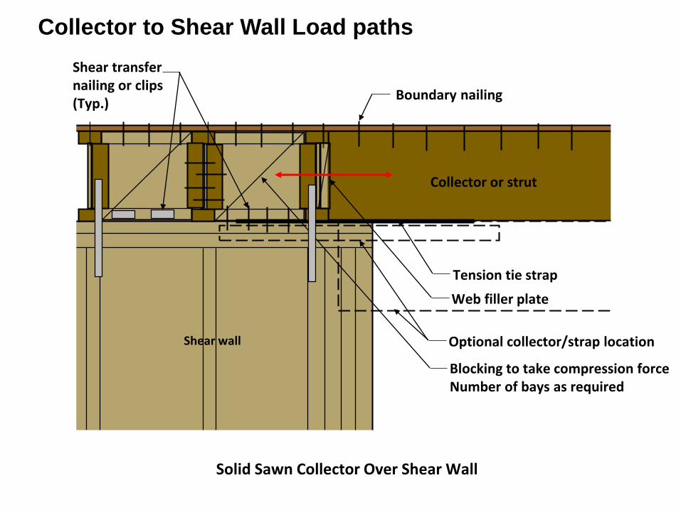
Solid Sawn Collector Over Shear Wall
Boundary nailing
Web filler plate
Tension tie strap
Shear transfer nailing or clips(Typ.)
Collector or strut
Blocking to take compression force Number of bays as required
Shear wall Optional collector/strap location
Collector to Shear Wall Load paths
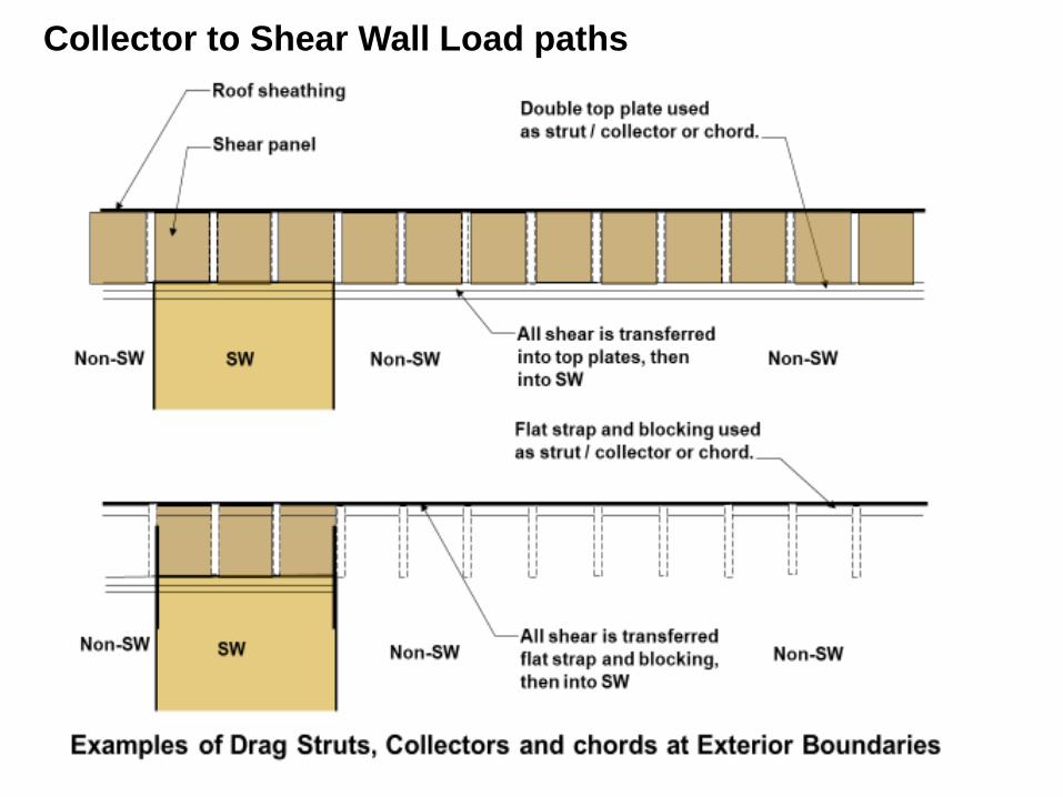
Collector to Shear Wall Load paths
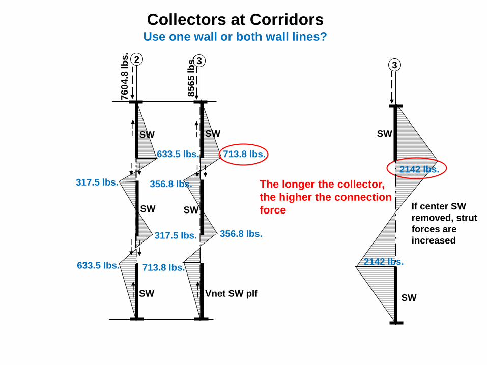
SW
3
Vnet SW plf
356.8 lbs.
SW
SW
2
633.5 lbs.
SW7
60
4.8
lb
s.
85
65
lb
s.
633.5 lbs.
SW
317.5 lbs.
317.5 lbs.
713.8 lbs.
713.8 lbs.
356.8 lbs.
SW
3
SW
If center SW
removed, strut
forces are
increased
Collectors at CorridorsUse one wall or both wall lines?
2142 lbs.
2142 lbs.
The longer the collector,
the higher the connection
force
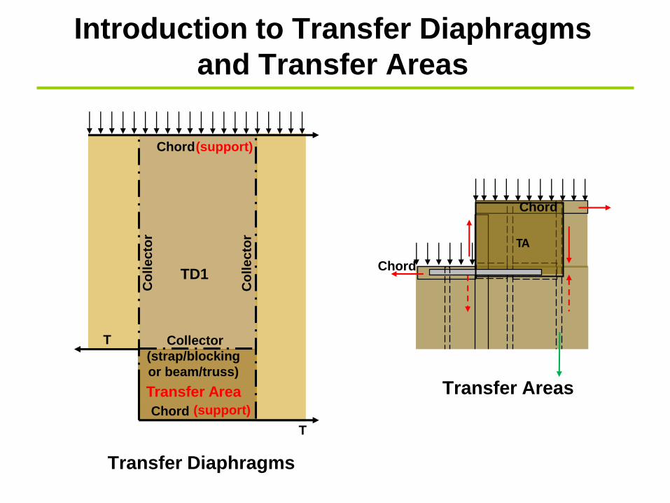
Introduction to Transfer Diaphragms
and Transfer Areas
Co
lle
cto
r
T Collector
(strap/blocking
or beam/truss)
(support)
(support)
Chord
Chord
TD1
Co
lle
cto
r
T
Transfer Area
TA
Transfer Diaphragms
Transfer Areas
Chord
Chord
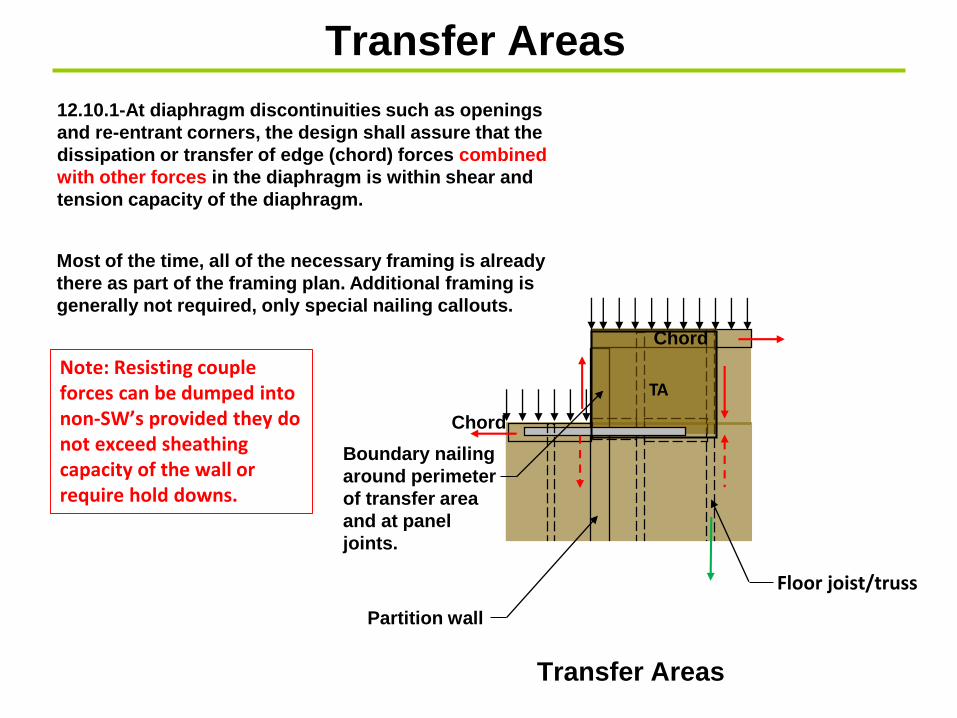
Transfer Areas
TA
Boundary nailing
around perimeter
of transfer area
and at panel
joints.
12.10.1-At diaphragm discontinuities such as openings
and re-entrant corners, the design shall assure that the
dissipation or transfer of edge (chord) forces combined
with other forces in the diaphragm is within shear and
tension capacity of the diaphragm.
Transfer Areas
Most of the time, all of the necessary framing is already
there as part of the framing plan. Additional framing is
generally not required, only special nailing callouts.
Chord
Chord
Note: Resisting couple forces can be dumped intonon-SW’s provided they do not exceed sheathing capacity of the wall or require hold downs.
Partition wall
Floor joist/truss
Co
lle
cto
r
T Collector
(strap/blocking
or beam/truss)
(support)
(support)
Chord
Chord
TD1
Co
lle
cto
r
T
Framing members, blocking, and connections shall extend
into the diaphragm a sufficient distance to develop the force
transferred into the diaphragm.(SDPWS 4.2.1)
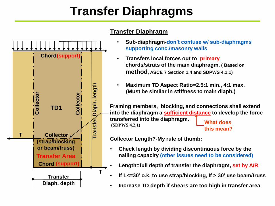
Transfer Diaphragm
• Sub-diaphragm-don’t confuse w/ sub-diaphragms
supporting conc./masonry walls
• Transfers local forces out to primary
chords/struts of the main diaphragm. ( Based on
method, ASCE 7 Section 1.4 and SDPWS 4.1.1)
• Maximum TD Aspect Ratio=2.5:1 min., 4:1 max.
(Must be similar in stiffness to main diaph.)
What does
this mean?
Collector Length?-My rule of thumb:
• Check length by dividing discontinuous force by the
nailing capacity (other issues need to be considered)
• Length=full depth of transfer the diaphragm, set by A/R
• If L<=30’ o.k. to use strap/blocking, If > 30’ use beam/truss
• Increase TD depth if shears are too high in transfer area
Transfer Area
Transfer
Diaph. depth
Tra
nsfe
r D
iap
h. le
ng
th
Transfer Diaphragms

SW
SW
Diaph.
C.L.
W ( plf)
Longitudinal Collector
Diaphragm chord
Discontinuous
diaphragm
chord
1 2
A
B
3
CDiaphragm chord
Dra
g s
tru
t
Diaphragm
support
Diaphragm
support
Transfer Diaphragm Members and Elements
4
Transfer
Area
Diaphragm chord
• The length of the collector is often
determined by dividing the collector
force by the diaphragm nailing capacity.
(Caution-other issues need to be considered!)
• The collector is often checked for
tension only. (Wrong!) Compression forces
occur when the loads reverse direction.
Typical callout
Steel tie strap x ga. x width x length with
(xx) 10d nails over 2x, 3x or 4x flat
blocking. Lap x’-y” onto wall.
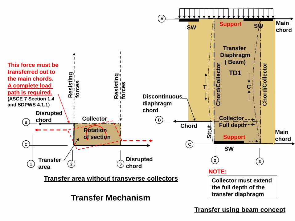
Transfer Mechanism
1 2
B
3
C
T C
Main
chord
Main
chord
B
C
A
2 3
Disrupted
chord
Re
sis
tin
g
forc
es
Transfer area without transverse collectors
Transfer using beam concept
Transfer
Diaphragm
( Beam)
Transfer
area
Disrupted
chord
Support
Support
Collector
Rotation
of section
This force must be
transferred out to
the main chords.
A complete load
path is required.(ASCE 7 Section 1.4
and SDPWS 4.1.1)
Collector must extend
the full depth of the
transfer diaphragm
NOTE:
SW
Collector
Full depthChord
Ch
ord
/Co
lle
cto
r
Str
ut
TD1
Ch
ord
/Co
lle
cto
r
SW
Discontinuous
diaphragm
chord
SW
Re
sis
tin
g
forc
es
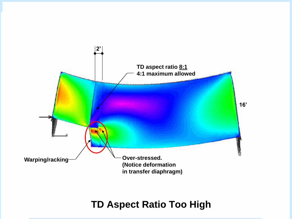
2’
16’
TD aspect ratio 8:1
4:1 maximum allowed
Over-stressed.
(Notice deformation
in transfer diaphragm)
TD Aspect Ratio Too High
Warping/racking
SW
Co
lle
cto
rT T
+
-
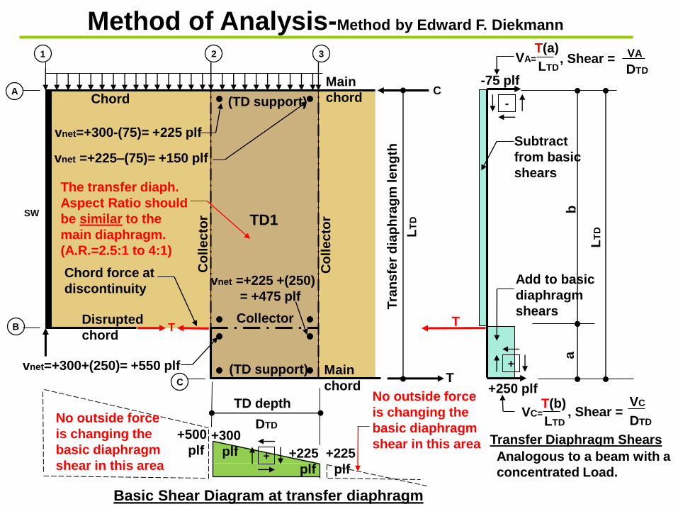
Analogous to a beam with a
concentrated Load.
Chord force at
discontinuity
Subtract
from basic
shears
Add to basic
diaphragm
shears
1
A
B
2
C
Collector
(TD support)
(TD support)
Chord
TD1
Basic Shear Diagram at transfer diaphragm
-75 plf
+250 plf
+300
plf +225 +225
plf plf
vnet=+300+(250)= +550 plf
vnet =+225–(75)= +150 plf
3
TD depthT
ran
sfe
r d
iap
hra
gm
le
ng
th
+
, Shear =VC
DTD DTD
, Shear = VA
DTD
vnet=+300-(75)= +225 plf
vnet =+225 +(250)
= +475 plf
Transfer Diaphragm Shears
ab
VA=
VC=
LT
D
T(b)
LTD
T(a)
LTD
LT
D
Method of Analysis-Method by Edward F. Diekmann
+500
plf
Main
chord
Main
chord
Disrupted
chord
The transfer diaph.
Aspect Ratio should
be similar to the
main diaphragm.
(A.R.=2.5:1 to 4:1)
No outside force
is changing the
basic diaphragm
shear in this area
No outside force
is changing the
basic diaphragm
shear in this area
T
C
Co
lle
cto
r
+ +
+ +
+225 plf +150 plf
+550 plf +475 plf
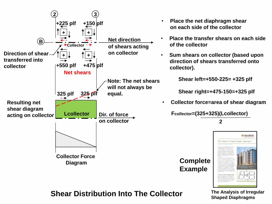
Resulting net
shear diagram
acting on collector
325 plf 325 plf
Net direction
of shears acting
on collector
Shear Distribution Into The Collector
Direction of shear
transferred into
collector
Collector
• Collector force=area of shear diagram
Shear left=+550-225= +325 plf
2
• Place the net diaphragm shear
on each side of the collector
• Sum shears on collector (based upon
direction of shears transferred onto
collector).
Fcollector=(325+325)(Lcollector)Dir. of force
on collector
B
2 3
Net shears
Note: The net shears
will not always be
equal.
Lcollector
• Place the transfer shears on each side
of the collector
Shear right=+475-150=+325 plf
Collector Force
Diagram
The Analysis of Irregular
Shaped Diaphragms
Complete
Example
SW
SW
(Typ.)
SW
SW (Typ.)
Tra
ns
ve
rse
walls
exterior walls
Corridor walls
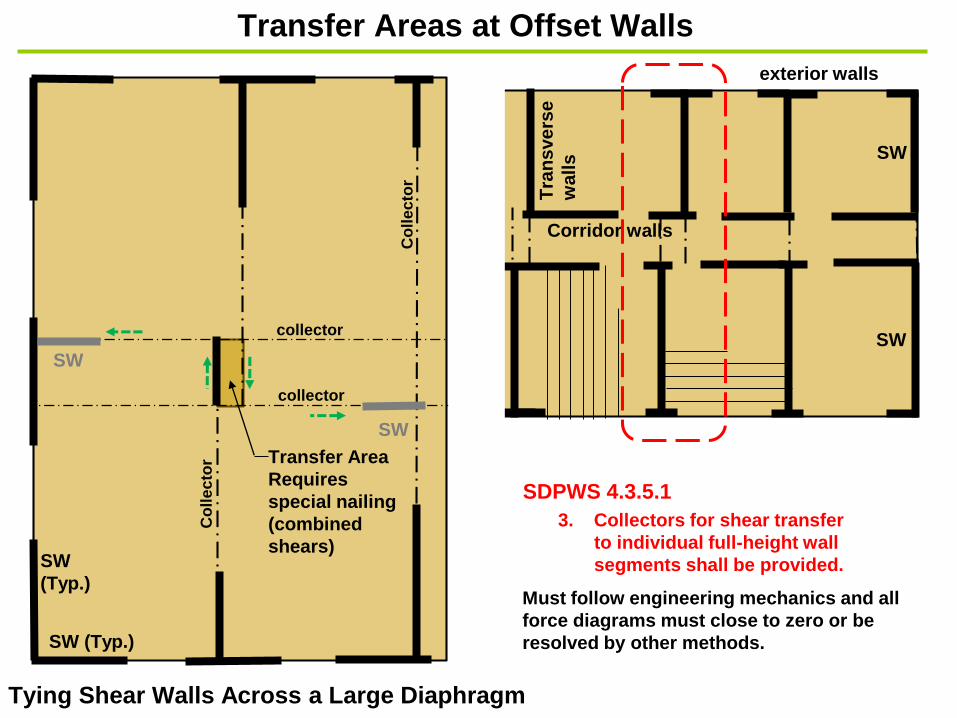
Transfer Area
Requires
special nailing
(combined
shears)
collector
Co
lle
cto
r
collector
Co
lle
cto
r
Transfer Areas at Offset Walls
Tying Shear Walls Across a Large Diaphragm
SW
SW
3. Collectors for shear transfer
to individual full-height wall
segments shall be provided.
SDPWS 4.3.5.1
Must follow engineering mechanics and all
force diagrams must close to zero or be
resolved by other methods.

Loads
Co
llecto
r
Struts /
collectors
The framing
member is not
designed or
detailed as a collector.
Corridor walls
There is almost always a
structural member in-line
with the shear wall that can
be used as a strut. Use it!
Jst. Jst.2x6/2x8
Tie straps
at all Joints
(typ.)
Typical Corridor Section
Mech.
Co
llecto
r
Co
llecto
r
Co
llecto
r
Layout 1 Layout 3Layout 2
Section
Section
Special nailing of
the sheathing to the
collector is required
the full length of the
collector (typ.)
Corridor walls
Co
llecto
r
SW SWSW
SW
Layout 4
Co
llecto
r
SW
SW
Co
llecto
r
Layout 5
Co
llecto
r
TATA
Preferred methods
Tying Shear Walls Across the Corridor
3. Collectors for shear transfer
to individual full-height wall
segments shall be provided.
SDPWS 4.3.5.1
SW
Diaphragm 1 Diaphragm 2
SW
1S
W2
1 2
B
3
C
A
D
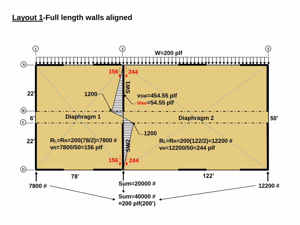
W=200 plf
78’ 122’
6’
22’
22’
50’
7800 # Sum=20000 # 12200 #
156
156 244
244
RL=RR=200(78/2)=7800 #
vR=7800/50=156 plfRL=RR=200(122/2)=12200 #
vR=12200/50=244 plf
Sum=40000 #
=200 plf(200’)
vSW=454.55 plf
vNet=54.55 plf
1200
1200
Layout 1-Full length walls aligned
Diaphragm 1 Diaphragm 2
SW
1
SW
2
SW3
1 2
B
3
C
A
D
4
SW4
11
2 p
lf8
8 p
lf
88
plf
11
2 p
lf
24 p
lf
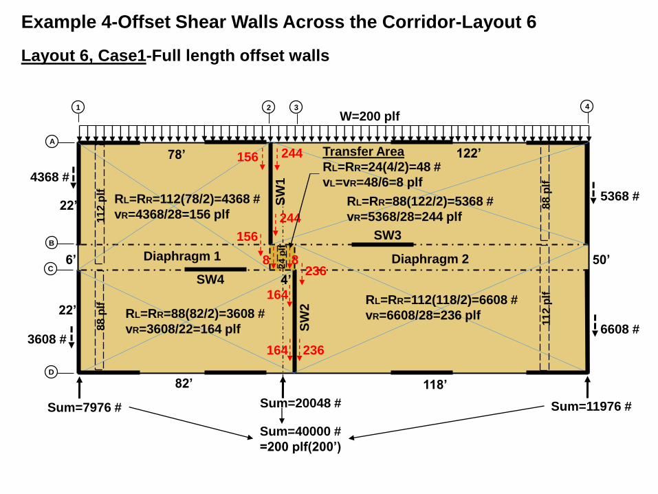
W=200 plf
78’ 122’
82’
4’
118’
6’
22’
22’
50’
Sum=7976 # Sum=20048 # Sum=11976 #
156
156
164 236
236
244
244
164
8 8
RL=RR=112(78/2)=4368 #
vR=4368/28=156 plf
4368 #
RL=RR=88(82/2)=3608 #
vR=3608/22=164 plf
RL=RR=88(122/2)=5368 #
vR=5368/28=244 plf
RL=RR=112(118/2)=6608 #
vR=6608/28=236 plf
3608 #
Transfer Area
RL=RR=24(4/2)=48 #
vL=vR=48/6=8 plf
Sum=40000 #
=200 plf(200’)
5368 #
6608 #
Layout 6, Case1-Full length offset walls
Example 4-Offset Shear Walls Across the Corridor-Layout 6

SW
1
SW
2
SW3
2
B
3
C
A
D
SW4
156
156
164 236
244
244
164
8
160
160240
240
Total load to grid lines 2 & 3
R23=4368+3608+48+5368+6608+48=20048 # O.K.
LSW=22+22=44’
VSW=20048 #
vSW=20048/44=455.64 plf
vnet SW1=455.64-156-244=55.64 plf
vnet SW2=455.64-164-236=55.64 plf Checks, they
should be equal
SW1
F2AB=55.64(22)=1224 #
F2BC=(156+8)6=984 #
F2C=1224-984=240 #
SW2
F3CD=55.64(22)=1224 #
F3CB=(236+8)6=1464 #
F3B=1224-1464= -240 #
FB23=FC23=240(4)/6=160 #
Shear at transfer area=240/6+8=48 plf
Sum=20048 #
1224
1224240
240
8 236
Summing V=0
Summing V=0
All forces in lb., all shears in plf
O.K.
Case 1-Smaller resulting forces at corridor
Diaphragm 1 Diaphragm 2S
W1
SW
2
SW3
1 2
B
3
C
A
D
4
SW4
11
2 p
lf8
8 p
lf
88
plf
11
2 p
lf
24 p
lf
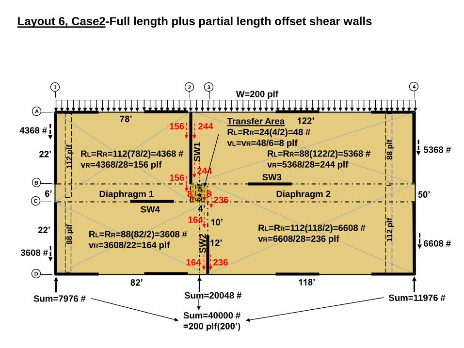
W=200 plf
78’ 122’
82’
4’
118’
6’
22’
22’
50’
Sum=7976 # Sum=20048 # Sum=11976 #
156
156
164 236
236
244
244
164
8 8
RL=RR=112(78/2)=4368 #
vR=4368/28=156 plf
4368 #
RL=RR=88(82/2)=3608 #
vR=3608/22=164 plf
RL=RR=88(122/2)=5368 #
vR=5368/28=244 plf
RL=RR=112(118/2)=6608 #
vR=6608/28=236 plf
3608 #
Transfer Area
RL=RR=24(4/2)=48 #
vL=vR=48/6=8 plf
Sum=40000 #
=200 plf(200’)
5368 #
6608 #
Layout 6, Case2-Full length plus partial length offset shear walls
10’
12’
SW
1
SW
2
SW3
2
B
3
C
A
D
SW4
156
156
164 236
244
244
164
8
2125.49
2125.493
18
8.2
4
31
88
.24
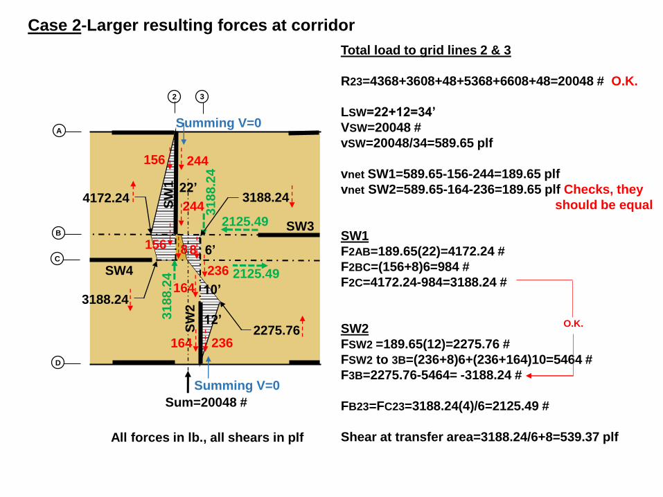
Total load to grid lines 2 & 3
R23=4368+3608+48+5368+6608+48=20048 # O.K.
LSW=22+12=34’
VSW=20048 #
vSW=20048/34=589.65 plf
vnet SW1=589.65-156-244=189.65 plf
vnet SW2=589.65-164-236=189.65 plf Checks, they
should be equal
SW1
F2AB=189.65(22)=4172.24 #
F2BC=(156+8)6=984 #
F2C=4172.24-984=3188.24 #
SW2
FSW2 =189.65(12)=2275.76 #
FSW2 to 3B=(236+8)6+(236+164)10=5464 #
F3B=2275.76-5464= -3188.24 #
FB23=FC23=3188.24(4)/6=2125.49 #
Shear at transfer area=3188.24/6+8=539.37 plf
Sum=20048 #
4172.24
2275.76
3188.24
3188.24
8
236
Summing V=0
Summing V=0
All forces in lb., all shears in plf
Case 2-Larger resulting forces at corridor
O.K.
22’
10’
12’
6’
Diaphragm 1 Diaphragm 2S
W2
SW3
1 2
B
3
C
A
D
4
SW4
11
2 p
lf8
8 p
lf
88
plf
11
2 p
lf
24 p
lf
W=200 plf
78’ 122’
82’
4’
118’
6’
22’
22’
50’
Sum=7976 # Sum=20048 # Sum=11976 #
156
156
164 236
236
244
244
164
8 8
RL=RR=112(78/2)=4368 #
vR=4368/28=156 plf
4368 #
RL=RR=88(82/2)=3608 #
vR=3608/22=164 plf
RL=RR=88(122/2)=5368 #
vR=5368/28=244 plf
RL=RR=112(118/2)=6608 #
vR=6608/28=236 plf
3608 #
Transfer Area
RL=RR=24(4/2)=48 #
vL=vR=48/6=8 plf
Sum=40000 #
=200 plf(200’)
5368 #
6608 #
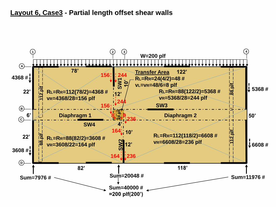
Layout 6, Case3 - Partial length offset shear walls
10’
12’
SW
1
10
’
12’

Total load to grid lines 2 & 3
R23=4368+3608+48+5368+6608+48=20048 # O.K.
LSW=12+10=22’
VSW=20048 #
vSW=20048/22=911.27 plf
vnet SW1=911.27-156-244=511.27 plf
vnet SW2=911.27-164-236=511.27 plf Checks, they
should be equal
SW1
FSW1=511.27(10)=5112.7 #
FSW1 to 2B=(156+244)12=4800 #
F2BC=(156+8)6=984 #
F2C=5112.7-4800-984=-671.3 #
SW2
FSW2=511.27(12)=6135.24 #
FSW2 to 3B=(236+8)6+(236+164)10=5464 #
F3B=6135.24-5464= 671.24 #
FB23=FC23=671.3(4)/6=120 #
Shear at transfer area=671.3/6+8=119.9 plf
SW
2
SW3
2
B
3
C
A
D
SW4
156
156
164 236
244
244
164
8
Sum=20048 #
671.24
8
236
Summing V=0
Summing V=0
All forces in lb., all shears in plf
Case 3-Smaller resulting forces at corridor
O.K.
10’
12’
6’
120
1206
71
.24
67
1.3
5112.7
6135.24
12’S
W1
10’
671.3
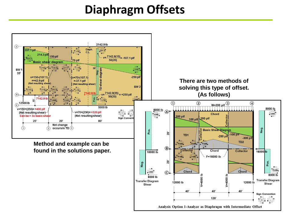
Diaphragm Offsets
Method and example can be
found in the solutions paper.
There are two methods of
solving this type of offset.
(As follows)
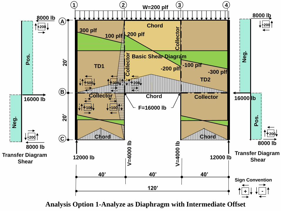
40’ 40’
120’
20’
300 plf200 plf100 plf
-200 plf
1 2
A
3
C
4W=200 plf
40’
TD1
TD2
+ -
Sign ConventionC
oll
ec
tor Chord +200
-200
Ne
g.
Po
s.
16000 lb
8000 lb
8000 lb
-200
+200
Po
s.
Neg
.
8000 lb
8000 lb
16000 lb
Co
lle
cto
r
20’
BCollector Collector
+500
+100 -100
+200
Chord
Analysis Option 1-Analyze as Diaphragm with Intermediate Offset
12000 lb12000 lb
F=16000 lb
V=
40
00
lb
V=
40
00
lb
Transfer Diagram
Shear
Transfer Diagram
Shear
Basic Shear Diagram
-100 plf
-300 plf
+300
Chord Chord

500 plf
200 plf
300 plf
-200 plf
-300 plf
Basic Shear Diagram
1 2
A
B
3
C
4
W=200 plf
Co
lle
cto
r
Co
lle
cto
r Chord
Chord
Chord
Chord
+100 -100
Chord
Chord
Chord Chord
W=
20
0 p
lf
W=
10
0 p
lfW
=1
00
plf
W=
10
0 p
lfW
=1
00
plf
W=100 plf W=100 plf
2000 lb2000 lb
Basic Shear DiagramBasic Shear Diagram
100 -100
20
00
lb
20
00
lb
12000 lb12000 lb
Analysis Option 2-Analyzing as separate diaphragms
20’
20’
40’
40’
120’
40’
Assumes small
diaphragms are
supported off of
main diaphragm
F=16000 lb
500 300 200 -500 plf
Q & A
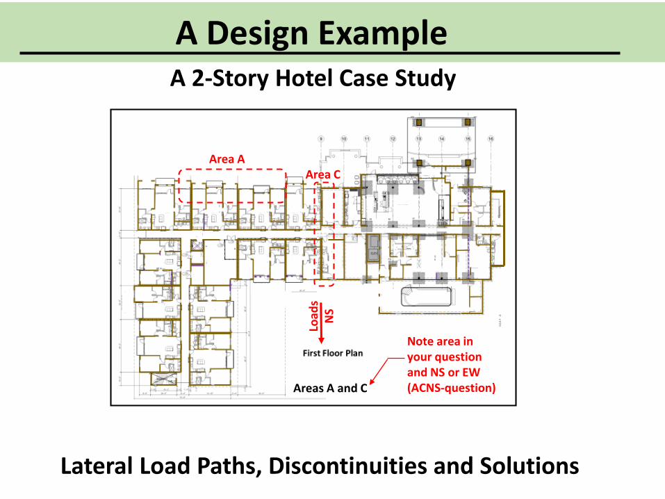
Lateral Load Paths, Discontinuities and Solutions
A Design ExampleA 2-Story Hotel Case Study
Areas A and C
Area CArea A
Note area in your questionand NS or EW(ACNS-question)
Load
sN
S

. .
..
. .
Vertical line-up of 1st and 2nd Floor SW’s
2nd Floor SW
1st Floor SW
Lobby-Amenities
Pool
• Shear walls can be intentionally placed to reduce complicated load paths.
• Offsets in the diaphragm create discontinuities in diaphragm chords and struts and also create offset shear walls.
Assumed FTAO shear walls
Re-entrant corner
Offset Walls
Alternate, additional wall options
Offset Walls
Discontinuous shear wall
Discontinuous shear walls at overhang
Optional shear walls
• Superimposing second floor shear walls over first floor shear walls allows verification of stacking and/or vertical discontinuities.
. .
..
. .
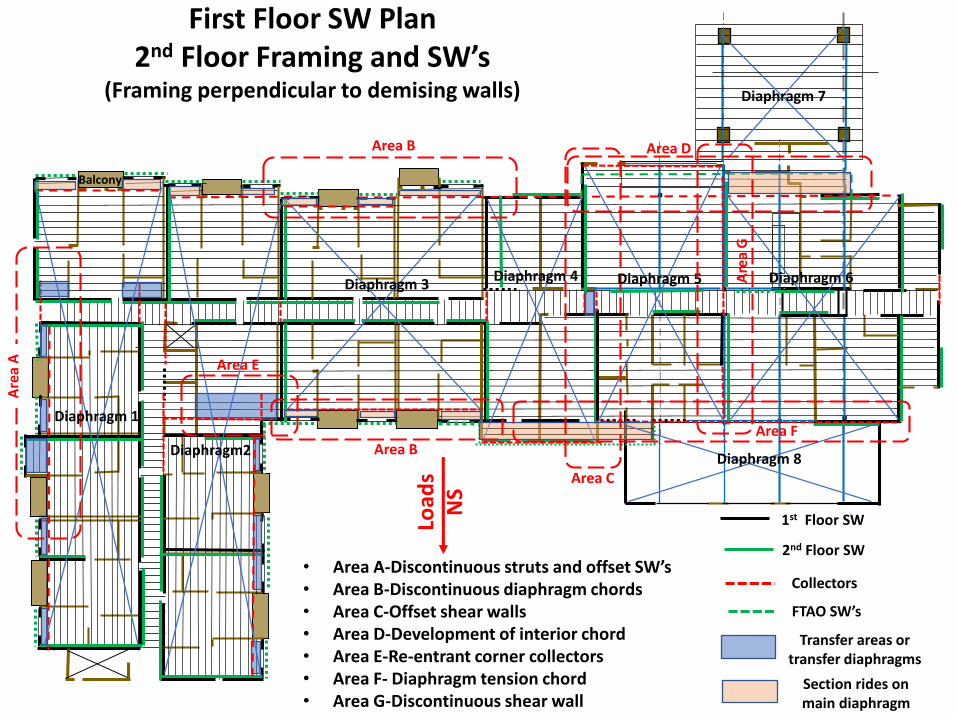
First Floor SW Plan2nd Floor Framing and SW’s
(Framing perpendicular to demising walls)
.
2nd Floor SW
1st Floor SW
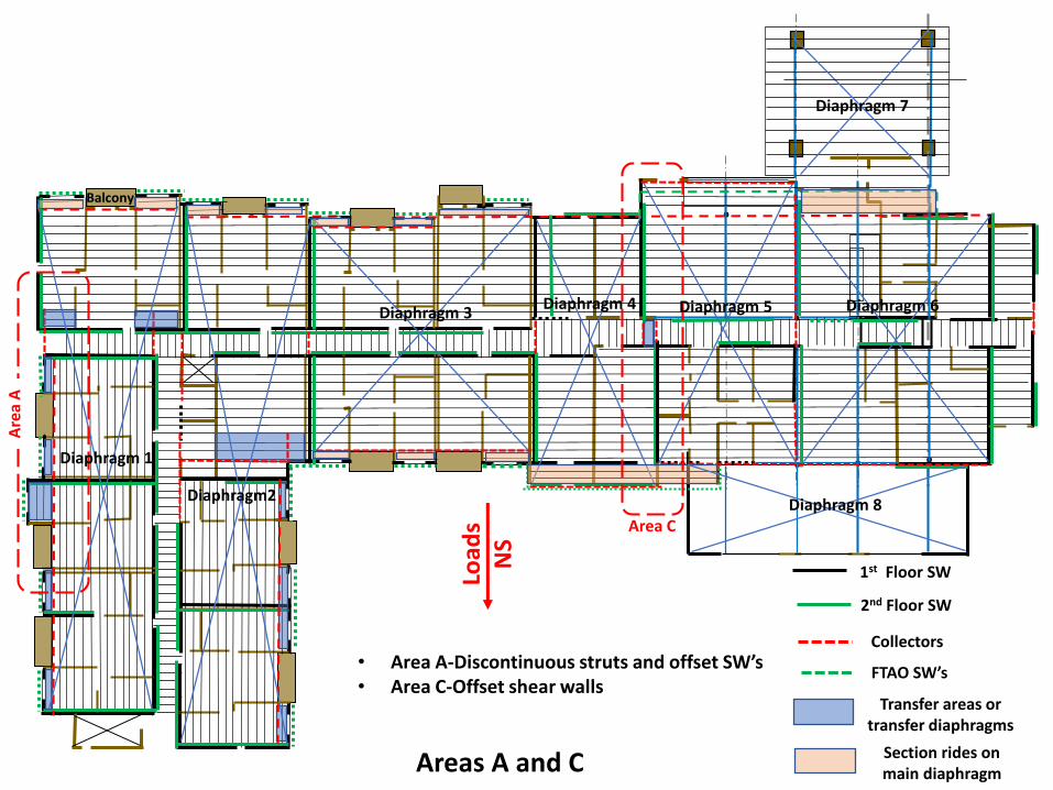
Collectors
Transfer areas or transfer diaphragms
Load
sN
S
Section rides on main diaphragm
Balcony
Diaphragm 4Diaphragm 3
Diaphragm2
Diaphragm 1
Diaphragm 8
Diaphragm 7
Diaphragm 6Diaphragm 5
Area B
Are
a A
Area C
Area D
Area B
Area E
Area F
Are
a G
• Area A-Discontinuous struts and offset SW’s• Area B-Discontinuous diaphragm chords• Area C-Offset shear walls• Area D-Development of interior chord• Area E-Re-entrant corner collectors• Area F- Diaphragm tension chord• Area G-Discontinuous shear wall
FTAO SW’s
. .
..
. . .
2nd Floor SW
1st Floor SW
Collectors
Transfer areas or transfer diaphragms
Load
sN
S
Section rides on main diaphragm
Balcony
Diaphragm 4Diaphragm 3
Diaphragm2
Diaphragm 1
Diaphragm 8
Diaphragm 7
Diaphragm 6Diaphragm 5
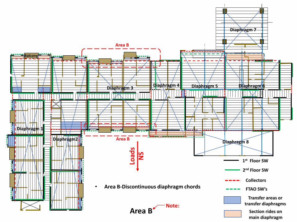
Area B
Area B
• Area B-Discontinuous diaphragm chords FTAO SW’s
Area BNote:
Balcony
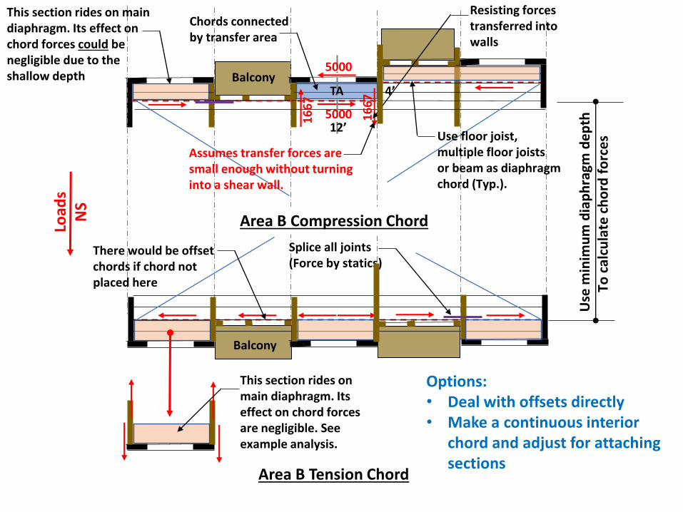
Area B Compression Chord
Balcony
Area B Tension Chord
Load
sN
S
Options:• Deal with offsets directly• Make a continuous interior
chord and adjust for attaching sections
TA
This section rides on main diaphragm. Its effect on chord forces could be negligible due to the shallow depth
Use floor joist, multiple floor joists or beam as diaphragm chord (Typ.).
5000
500016
67
16
67 4’
12’
This section rides on main diaphragm. Its effect on chord forces are negligible. See example analysis.
Chords connected by transfer area
Resisting forces transferred into walls
Splice all joints(Force by statics)
Use
min
imu
m d
iap
hra
gm d
ep
thTo
cal
cula
te c
ho
rd f
orc
es
There would be offset chords if chord not placed here
Assumes transfer forces are small enough without turning into a shear wall.
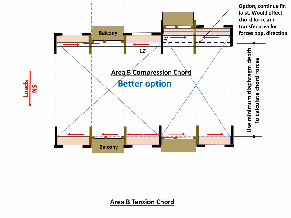
Balcony
Area B Compression Chord
Balcony
Area B Tension Chord
Load
sN
S4’
12’
Use
min
imu
m d
iap
hra
gm d
ep
thTo
cal
cula
te c
ho
rd f
orc
es
Better option
Option, continue flr. joist. Would effect chord force and transfer area for forces opp. direction
. .
..
. . .
2nd Floor SW
1st Floor SW
Collectors
Transfer areas or transfer diaphragms
Load
sN
S
Section rides on main diaphragm
Balcony
Diaphragm 4Diaphragm 3
Diaphragm2
Diaphragm 1
Diaphragm 8
Diaphragm 7
Diaphragm 6Diaphragm 5
Are
a A
Area C
• Area A-Discontinuous struts and offset SW’s• Area C-Offset shear walls
FTAO SW’s
Areas A and C
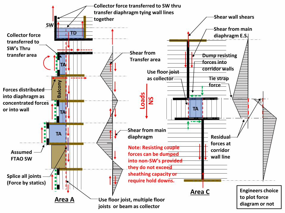
Bal
con
y
Load
sN
S
Area AArea C
TD
TA
TA
TA
TA
Shear from main diaphragm
Tie strap force
Residual forces at corridor wall line
Assumed FTAO SW
Shear from Transfer area
Use floor joist, multiple floor joists or beam as collector
Use floor joistas collector
Shear from main diaphragm E.S.
Shear wall shears
Dump resisting forces into corridor walls
Forces distributed into diaphragm as concentrated forces or into wall
Engineers choice to plot force diagram or not
Collector force transferred to SW’s Thru transfer area
SW
Collector force transferred to SW thru transfer diaphragm tying wall lines together
Note: Resisting couple forces can be dumped into non-SW’s provided they do not exceed sheathing capacity or require hold downs.
Splice all joints(Force by statics)
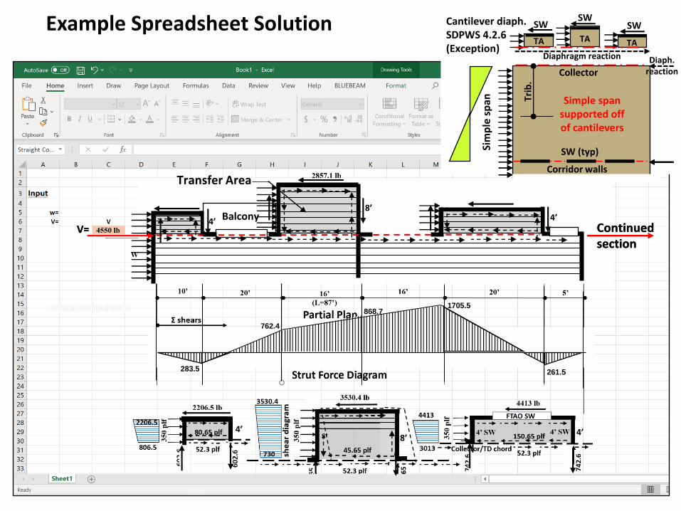
Example Spreadsheet Solution
Simple span supported off of cantilevers
Trib
.
SW (typ)
SWSWSW
Continued sectionContinued section
Transfer Area
BalconyV=V=
261.5
868.71705.5
762.4
283.5
Corridor walls
Collector
Diaphragm reaction Diaph. reaction
Sim
ple
sp
an
Cantilever diaph. SDPWS 4.2.6 (Exception)
TA TA TA
4’8’
4’
4’
8’4’

. .
..
. . .
2nd Floor SW
1st Floor SW
Collectors
Transfer areas or transfer diaphragms
Load
sN
S
Section rides on main diaphragm
Balcony
Diaphragm 4Diaphragm 3
Diaphragm2
Diaphragm 1
Diaphragm 8
Diaphragm 7
Diaphragm 6Diaphragm 5
Area E
• Area E-Re-entrant corner collectorsFTAO SW’s
Area E
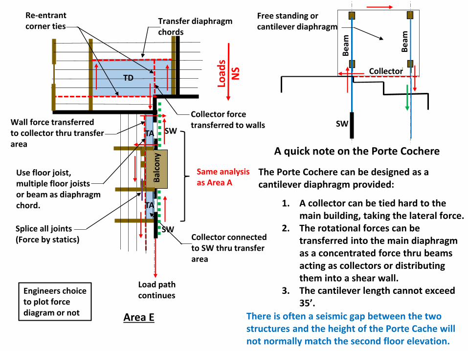
Area E
Bal
con
y
Load
sN
S
Re-entrant corner ties
TD
TA
TA
Transfer diaphragm chords
Collector force transferred to walls
Same analysis as Area A
SW
SW
Wall force transferred to collector thru transferarea
Collector connected to SW thru transfer area
Load path continues
Use floor joist, multiple floor joists or beam as diaphragm chord.
Engineers choice to plot force diagram or not
Splice all joints(Force by statics)
A quick note on the Porte Cochere
The Porte Cochere can be designed as a cantilever diaphragm provided:
1. A collector can be tied hard to the main building, taking the lateral force.
2. The rotational forces can be transferred into the main diaphragm as a concentrated force thru beams acting as collectors or distributing them into a shear wall.
3. The cantilever length cannot exceed 35’.
SW
There is often a seismic gap between the two structures and the height of the Porte Cache will not normally match the second floor elevation.
Be
am
Be
am
Collector
Free standing or cantilever diaphragm
. .
..
. . .
2nd Floor SW
1st Floor SW
Collectors
Transfer areas or transfer diaphragms
Load
sN
S
Section rides on main diaphragm
Balcony
Diaphragm 4Diaphragm 3
Diaphragm2
Diaphragm 1
Diaphragm 8
Diaphragm 7
Diaphragm 6Diaphragm 5
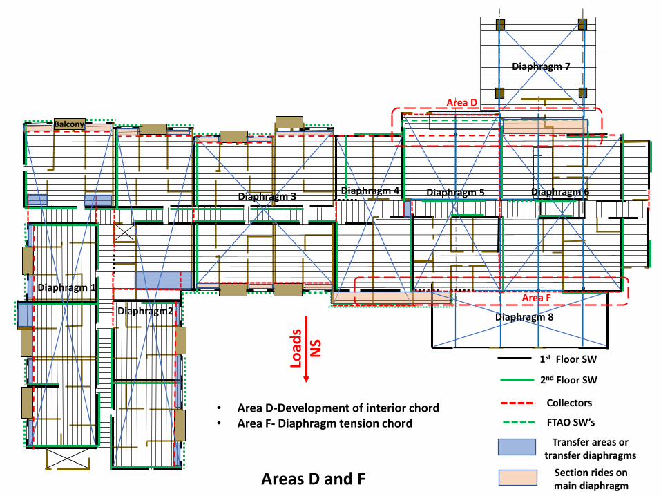
Area D
Area F
• Area D-Development of interior chord• Area F- Diaphragm tension chord FTAO SW’s
Areas D and F
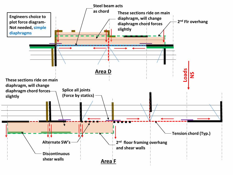
Area D
Area F
Tension chord (Typ.)
These sections ride on main diaphragm, will change diaphragm chord forces slightly
2nd floor framing overhang and shear walls
Load
sN
S
Steel beam acts as chord These sections ride on main
diaphragm, will change diaphragm chord forces slightly
Alternate SW’s
2nd Flr overhang
Discontinuous shear walls
Engineers choice to plot force diagram-Not needed, simple diaphragms
Splice all joints(Force by statics)
. .
..
. . .
2nd Floor SW
1st Floor SW
Collectors
Transfer areas or transfer diaphragms
Load
sN
S
Section rides on main diaphragm
Balcony
Diaphragm 4Diaphragm 3
Diaphragm2
Diaphragm 1
Diaphragm 8
Diaphragm 7
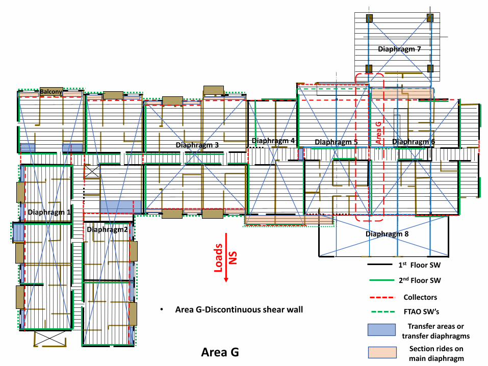
Diaphragm 6Diaphragm 5 Are
a G
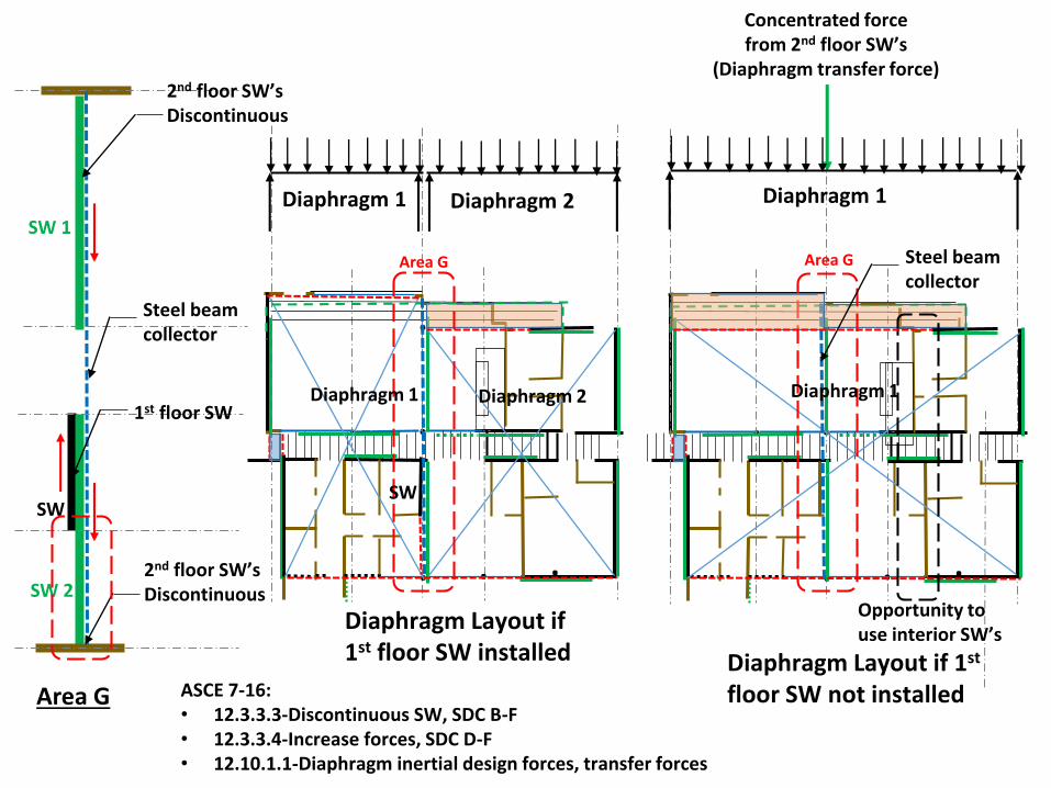
• Area G-Discontinuous shear wall FTAO SW’s
Area G
Area G
.
..
. . .
Area G
.
..
. . .
Area G
Concentrated force from 2nd floor SW’s
(Diaphragm transfer force)
Diaphragm 1
SW
Diaphragm 1Diaphragm 2
Diaphragm Layout if 1st floor SW installed
SW
Diaphragm Layout if 1st
floor SW not installed
SW 2
SW 1
2nd floor SW’sDiscontinuous
Steel beam collector
ASCE 7-16:• 12.3.3.3-Discontinuous SW, SDC B-F• 12.3.3.4-Increase forces, SDC D-F• 12.10.1.1-Diaphragm inertial design forces, transfer forces
2nd floor SW’sDiscontinuous
1st floor SWDiaphragm 1 Diaphragm 1Diaphragm 2
Steel beam collector
Opportunity to use interior SW’s
. .
..
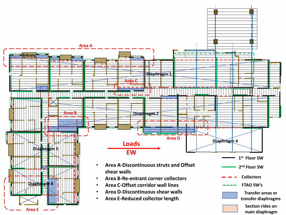
. . .
2nd Floor SW
1st Floor SW
Collectors
Transfer areas or transfer diaphragms
LoadsEW
Section rides on main diaphragm
Balcony
Diaphragm 4
Diaphragm 2
Diaphragm 1
Diaphragm 6
Diaphragm 5
Area A
Area C
Area B
Area D
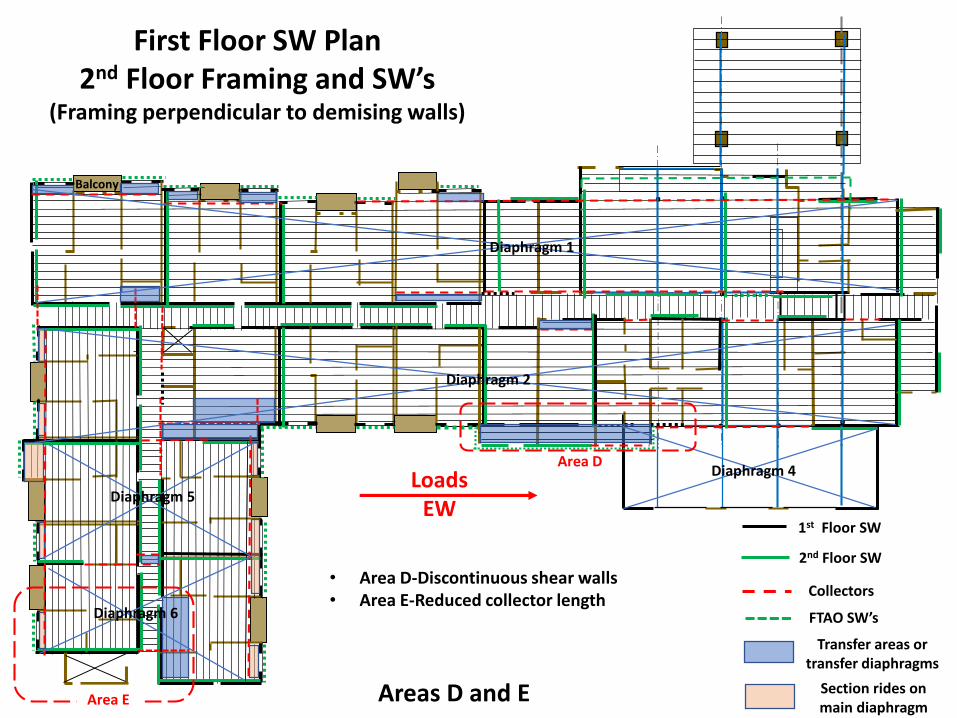
• Area A-Discontinuous struts and Offset shear walls
• Area B-Re-entrant corner collectors• Area C-Offset corridor wall lines• Area D-Discontinuous shear walls• Area E-Reduced collector length
Area E
FTAO SW’s
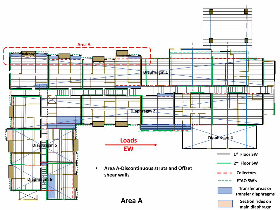
. .
..
. . .
2nd Floor SW
1st Floor SW
Collectors
Transfer areas or transfer diaphragms
LoadsEW
Section rides on main diaphragm
Balcony
Diaphragm 4
Diaphragm 2
Diaphragm 1
Diaphragm 6
Diaphragm 5
Area A
• Area A-Discontinuous struts and Offset shear walls
FTAO SW’s
Area A
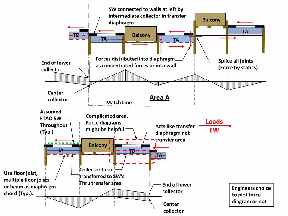
Balcony
Area A
LoadsEW
TA
TATA
Center collector
End of lower collector
Acts like transfer diaphragm not transfer area
TATDTA
TD
Match Line
Balcony
Balcony
SW connected to walls at left by intermediate collector in transfer diaphragm
Center collector
End of lower collector
Assumed FTAO SW Throughout (Typ.)
Forces distributed into diaphragm as concentrated forces or into wall
Collector force transferred to SW’s Thru transfer area
Splice all joints(Force by statics)
Engineers choice to plot force diagram or not
Complicated area. Force diagrams might be helpful
Use floor joist, multiple floor joists or beam as diaphragm chord (Typ.).

. .
..
. . .
2nd Floor SW
1st Floor SW
Collectors
Transfer areas or transfer diaphragms
LoadsEW
Section rides on main diaphragm
Balcony
Diaphragm 4
Diaphragm 2
Diaphragm 1
Diaphragm 6
Diaphragm 5
Area B
• Area B-Re-entrant corner collectors• Area C-Offset corridor wall lines
FTAO SW’s
Area C
Areas B and C
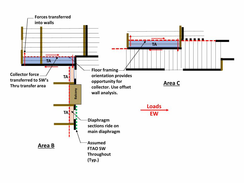
LoadsEW
Floor framing orientation provides opportunity for collector. Use offset wall analysis.
Bal
con
yTA
TA
TA
Area B
TA
Area C
Diaphragm sections ride on main diaphragm
Forces transferred into walls
Collector force transferred to SW’s Thru transfer area
Assumed FTAO SW Throughout (Typ.)
. .
..
. . .
2nd Floor SW
1st Floor SW
Collectors
Transfer areas or transfer diaphragms
LoadsEW
Section rides on main diaphragm
Balcony
Diaphragm 4
Diaphragm 2
Diaphragm 1
Diaphragm 6
Diaphragm 5
Area D
• Area D-Discontinuous shear walls• Area E-Reduced collector length
Area E
FTAO SW’s
Areas D and E
First Floor SW Plan2nd Floor Framing and SW’s
(Framing perpendicular to demising walls)
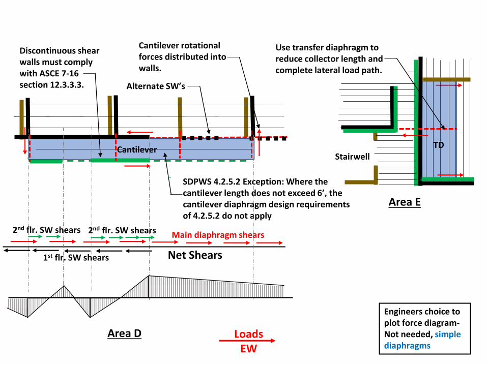
Area D
Cantilever
LoadsEW
SDPWS 4.2.5.2 Exception: Where the cantilever length does not exceed 6’, the cantilever diaphragm design requirements of 4.2.5.2 do not apply
Discontinuous shear walls must comply with ASCE 7-16 section 12.3.3.3.
Cantilever rotational forces distributed into walls.
Area E
Use transfer diaphragm to reduce collector length and complete lateral load path.
Alternate SW’s
TD
2nd flr. SW shears Main diaphragm shears2nd flr. SW shears
1st flr. SW shears
Engineers choice to plot force diagram-Not needed, simple diaphragms
Stairwell
Net Shears
. .
..
.
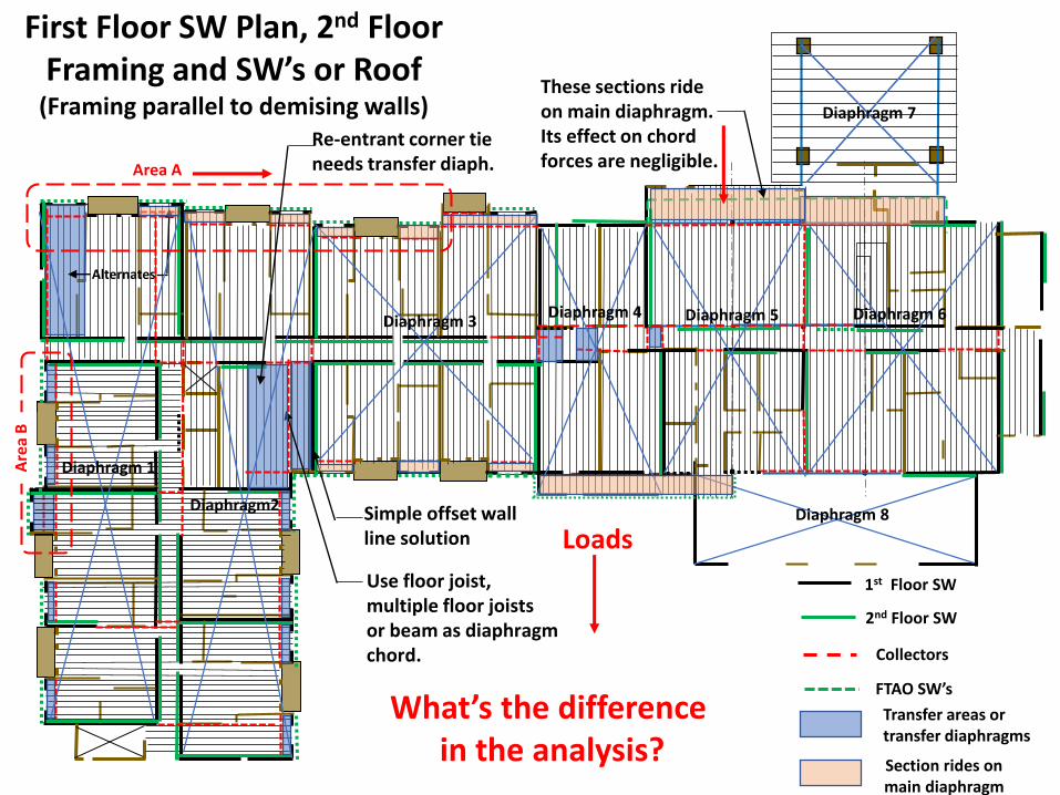
First Floor SW Plan, 2nd Floor Framing and SW’s or Roof
(Framing parallel to demising walls)
2nd Floor SW
1st Floor SW
Collectors
Transfer areas or transfer diaphragms
Alternates
.
Diaphragm 4Diaphragm 3
Diaphragm2
Diaphragm 1
Diaphragm 8
Diaphragm 7
Diaphragm 6Diaphragm 5
Simple offset wall line solution
Area A
Are
a B
These sections ride on main diaphragm. Its effect on chord forces are negligible.
Use floor joist, multiple floor joists or beam as diaphragm chord.
What’s the difference in the analysis?
Section rides on main diaphragm
Re-entrant corner tie needs transfer diaph.
FTAO SW’s
Loads
TA
TD
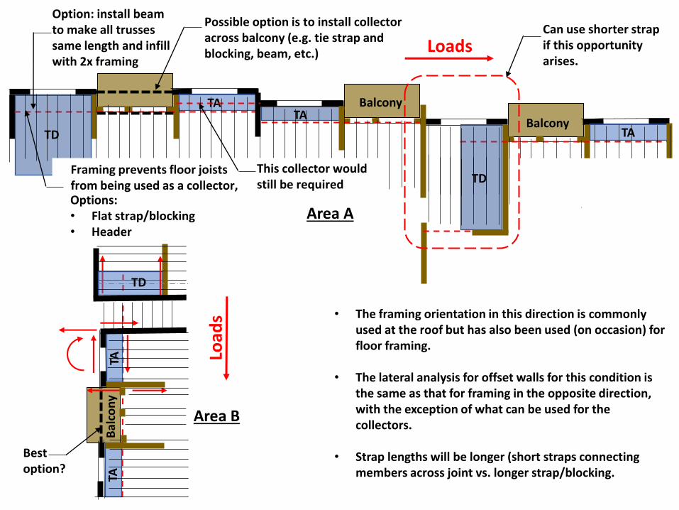
Balcony
Balcony
Possible option is to install collector across balcony (e.g. tie strap and blocking, beam, etc.)
This collector would still be required
Bal
con
y
TD
TATA
Loads
Load
s • The framing orientation in this direction is commonly used at the roof but has also been used (on occasion) for floor framing.
• The lateral analysis for offset walls for this condition is the same as that for framing in the opposite direction, with the exception of what can be used for the collectors.
• Strap lengths will be longer (short straps connecting members across joint vs. longer strap/blocking.
Options:• Flat strap/blocking• Header
Framing prevents floor joists from being used as a collector,
Area A
Area B
TD
Can use shorter strap if this opportunity arises.
Bestoption?
Option: install beam to make all trusses same length and infill with 2x framing
TA
TA
Q & AThe area of the plan under discussion is noted at the bottom of the slide.
Please note the area and direction of load, NS or EW, at the start of your question.
Example: “B-NS”… question

This concludes Woodworks Presentation on:
A Master Class on Wood Lateral-Resisting Systems
Your comments and suggestions are
valued. They will make a difference.
Send to: [email protected]
R. Terry Malone, P.E., S.E.
Senior Technical Director
WoodWorks.org
Contact Information:
928-775-9119
Disclaimer:
The information in this publication, including, without limitation, references to information contained in other publications or made available
by other sources (collectively “information”) should not be used or relied upon for any application without competent professional
examination and verification of its accuracy, suitability, code compliance and applicability by a licensed engineer, architect or other
professional. This example has been developed for informational purposes only. It is not intended to serve as recommendations or as the only
method of analysis available. Neither the Wood Products Council nor its employees, consultants, nor any other individuals or entities who
contributed to the information make any warranty, representative or guarantee, expressed or implied, that the information is suitable for any
general or particular use, that it is compliant with applicable law, codes or ordinances, or that it is free from infringement of any patent(s), nor
do they assume any legal liability or responsibility for the use, application of and/or reference to the information. Anyone making use of the
information in any manner assumes all liability arising from such use.
Thank You