a low cost single-axis sun tracker system using pic ... · a low cost single-axis sun tracker...
TRANSCRIPT

65
ISSN 1999-8716
Printed in Iraq Vol. 05, No. 01, pp.65-78, June 2012
A LOW COST SINGLE-AXIS SUN TRACKER SYSTEM USING PIC MICROCONTROLLER
Kais I. Abdul-lateef
University of Technology, Control and systems Eng. dep., Iraq-Baghdad E-mail : [email protected]
(Received:20/3/2011 ; Accepted:5/4/2011)
ABSTRACT:- Solar energy is rapidly gaining importance as an energy resource. To make solar energy more viable, efficiency of solar panel systems must be maximized. A feasible approach to maximize the efficiency of solar panel systems is sun tracking. A solar panel receives the most sunlight when it is perpendicular to the sun’s rays. This paper is about moving a solar panel along with the direction of sunlight; it uses a geared motor to change the position of the solar panel, the motor is controlled by the PIC16F84A microcontroller, which detects the sunlight using photocells. The objective is to design and implement an automated, one-axis solar-tracking mechanism using embedded system design with minimum cost and reliable structure . KEYWORDS: PIC microcontroller, photocell, one-axis tracking, solar energy, dc drives.
1. INTRODUCTION
We are entering a new solar age. For the last few hundred years humans have been using up fossil fuels that took around 400 million years to form and store underground. We must now put huge effort, technological and political , into energy systems that use the sun’s energy more directly. It is one of the most inspiring challenges facing today’s engineers and scientists (1).
Photovoltaic (PV), is one of the exciting new technologies that is already helping us towards a solar future. The PV panels are usually mounted on the roof of the house or at a near open area to face the sun. The custom is to fix these solar modules position angle to the country latitude angle (2). If possible, seasonally some people try to adjust the module’s direction manually towards the sun(3,4). However to collect as much solar radiations as possible, it is more convenient and efficient to use a sun tracking system(5). In photovoltaic tracking systems, the surface of the module tracks the sun throughout the day. In order to ensure maximum power output from PV cells, the sunlight’s angle of incidence needs to be constantly perpendicular to the solar panel. This requires constant tracking of the sun’s apparent daytime motion, and hence develops an automated sun tracking system which carries the solar panel and positions it in such a way that direct sunlight is always focused on the PV cells (6). Moving to automatic tracking, this can be around either one or two axes. One - axis tracking is generally adequate for non-concentrating systems and for systems using low - to - medium concentrations. Many systems, including large power plants, are based on flat plate PV modules and use tracking without any concentration (4).
In this paper a sun taking systems is proposed. The system controls the movement of a solar panel so that it is constantly aligned towards the direction of the sun. The solar tracker designed and constructed in this paper offers a reliable and affordable method of aligning a
Diyala Journal of Engineering
Sciences
A LOW COST SINGLE-AXIS SUN TRACKER SYSTEM USING PIC MICROCONTROLLER
Diyala Journal of Engineering Sciences, Vol. 05, No. 01, June 2012 66
solar panel with the sun in order to maximize its energy output. The sun tracker system is a hybrid hardware and software prototype designed around Programmable Intelligent Computer (PIC), which automatically provides best alignment of solar panel with the sun. Two Cadmium Sulfide (CdS) photoresistors are used to sense the light intensity. The CdS photoresistors is a light dependent resistor (LDR),it is basically a photocell that is sensitive to light (7) . Software will be developed which would allow the PIC to detect and obtain its data from the two CdS or LDR cells ( sensor A and sensor B) and then compare their resistances. The two sensors will be positioned in such a way, so that if one of the two comes under a shadow, the PIC microcontroller will detect the difference in resistance and thus actuate the motor to move the solar panel into a position where the light upon both sensors is equal.
2. THE LIGHT DEPENDENT RESISTORS
To track the sun , the system should work in closed loop form, the controller needs to sense the light through a light sensor. For this purpose a light dependent resistor (LDR) were used. The LDR consists of a disc of semiconductor material with two electrodes on its surface. In the dark or in dim light, the material of the disc has a relatively small number of free electrons in it. There are few electrons to carry electric charge. This means that it is a poor conductor of electric current; Its resistance is high. In the light, more electrons escape from the atoms of the semiconductor. There are more electrons to carry electric charge. It becomes a good conductor; Its resistance is low. The more light, the more electrons, the lower the resistance. The LDR used in this paper is the CdS photoresistor shown in Fig 1. The LDR used has a dark resistance of about 100 kΩ and light resistance of 10 kΩ . From the graph shown in Fig. 2, it can be clearly seen that the resistance of the LDR is inversely proportional to the light intensity that as the light intensity increases the resistance of the LDR decreases (8).
3. THE PIC16F84A MICROCONTROLLER ARCHITECTURE
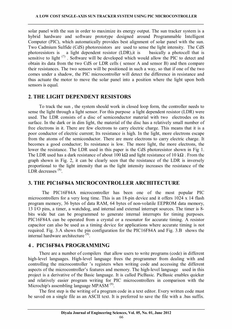
The PIC16F84A microcontroller has been one of the most popular PIC microcontrollers for a very long time. This is an 18-pin device and it offers 1024 x 14 flash program memory, 36 bytes of data RAM, 64 bytes of non-volatile EEPROM data memory, 13 I/O pins, a timer, a watchdog, and internal and external interrupt sources. The timer is 8-bits wide but can be programmed to generate internal interrupts for timing purposes. PIC16F84A can be operated from a crystal or a resonator for accurate timing. A resistor capacitor can also be used as a timing device for applications where accurate timing is not required. Fig. 3.A shows the pin configuration for the PIC16F84A and Fig. 3.B shows the internal hardware architecture (9).
4 . PIC16F84A PROGRAMMING
There are a number of compilers that allow users to write programs (code) in different high-level languages. High-level language frees the programmer from dealing with and controlling the microcontroller ’s registers when writing code and accessing the different aspects of the microcontroller’s features and memory. The high-level language used in this project is a derivative of the Basic language. It is called PicBasic. PicBasic enables quicker and relatively easier program writing for PIC microcontrollers in comparison with the Microchip's assembling language MPASM (9).
The first step is the writing of a program code in a text editor. Every written code must be saved on a single file as an ASCII text. It is preferred to save the file with a .bas suffix.

A LOW COST SINGLE-AXIS SUN TRACKER SYSTEM USING PIC MICROCONTROLLER
Diyala Journal of Engineering Sciences, Vol. 05, No. 01, June 2012 67
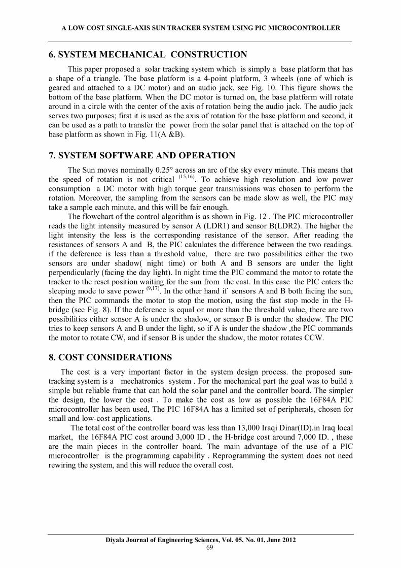
The compiler will read the file with or without the .bas suffix. The .bas suffix will help to identify the PIC programs in a crowded directory. An example of one simple BASIC program is Program_name.BAS is given in the diagram shown in Fig. 4. When the original BASIC program is finished and saved as a single file with .BAS ending it is necessary to start PIC BASIC compiler. The compiling procedure takes place in two consecutive steps; In the first step the compiler will convert BAS file into assembler’s code and save it as Program_name.ASM file. In the second step the compiler automatically calls assembler, which converts ASM - type file into an executable HEX code ready to be downloaded into the programming memory of a PIC microcontroller.
To download the programming instructions into the chip, a programming device is needed. Besides writing of a program code into the programming memory, the programming device serves to set the configuration of a microcontroller, the type of the oscillator, protection of the memory against reading, switching on of a watchdog timer etc. The PIC 16F84A is a versatile microcontroller with flash memory. Flash memory is a term used to describe this type of rewritable memory. The PIC microcontroller can be programmed and reprogrammed at least 1000 times (9).
5. THE CONTROLLER BOARD
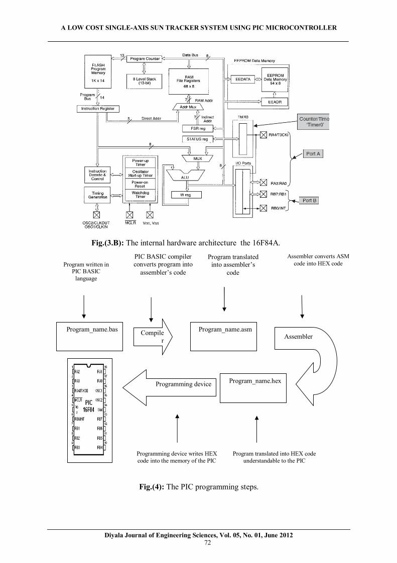
The controller board consist of three parts: the PIC microcontroller which represents the brain of the system, the sensing part which represents the 'eyes' , and the motor part or the actuator. Fig. 5 shows the controller board, and Fig. 6 shows the complete circuit diagram.
5.1. THE 16F84A CLOCK OSCILLATOR
The choice of microcontroller clock source determines some of its fundamental operating characteristics. While “faster is better” in terms of operating speed and programming execution, faster is definitely worse in terms of power consumption, and also possibly in terms of electromagnetic interference. All timed elements within the microcontroller almost invariably depend on the clock characteristics. If stable and accurate timing is required, then the clock oscillator must be stable and accurate (9). The 16F84A can be configured to operate in four different oscillator modes, allowing implementation of RC, crystal or ceramic oscillators. It can also accept an external clock source . The user selects which mode is to be used by setting the oscillator mode during the PIC programming. 4MHz oscillator is considered an optimum choice when working with applications such as Solar Tracking (10).4MHz crystal and two (22pF) capacitors make up an oscillator that is required by the microcontroller. see Fig. 6. 5.2. VOLTAGE REGULATION
The DC motor does not require voltage regulation; however, the PIC microcontroller does require a steady, regulated 5 volts. The LM7805 voltage regulator, in Fig. 7 was used such that a regulated 5 volt supply could be accomplished (11) . This circuit takes an unregulated supply (6-9 volts) and makes available from this a regulated 5 volt (Vcc) supply, which is used for powering the PIC. Since the DC motor used requires 9 volts for operation, this value was used as the input voltage to the regulator circuit. The reason for this is to limit the number of power rails to two (9V & 5V) in the circuit design.

A LOW COST SINGLE-AXIS SUN TRACKER SYSTEM USING PIC MICROCONTROLLER
Diyala Journal of Engineering Sciences, Vol. 05, No. 01, June 2012 68
5.3.THE H-BRIDGE MOTOR DRIVER
The PIC controls the rotation of the base platform, in both directions, clockwise (CW) and counterclockwise (CCW). To reverse the rotation direction of the PM DC motor, the polarity of the applied voltage must be reversed. One way to accomplish this is to have a motor-driver amplifier capable of outputting a positive and negative voltage. When the drive voltage is positive with respect to ground, the motor turns CW. When the drive voltage is negative with respect to ground, the voltage polarity at the motor terminals reverses and the motor rotates CCW. The L298 power op-amp (Fig. 8) is capable of providing positive and negative output voltages (12). The L298 is an integrated monolithic circuit in a 15- lead multi watt package. It is a high voltage, high current dual full-bridge driver designed to accept standard TTL logic levels and drive inductive loads such as relays, solenoids, DC and stepping motors. Two enable inputs are provided to enable or disable the device independently of the input signals. Fig. 8 shows a bidirectional DC motor control schematic diagram for which only one bridge is needed. The external bridge of diodes D1 to D4 is made by four fast recovery elements that must be chosen of a VF as low as possible at the worst case of the load current. The brake function (Fast motor stop) requires that the absolute maximum rating of 2 Amps must never be overcome.
The PIC microcontroller is very sensitive to electrical spikes (which may cause a reset or lockup), to solve this problem an external bridge of diodes are required when inductive loads are driven; The diodes function is to stop any electrical spikes caused by switching the motor’s winding on and off. The diodes are also necessary when the inputs of the IC are chopped; Shottky diodes would be preferred. This solution can drive until 3 Amps in DC operation and until 3.5 Amps of a repetitive peak current. To increase the immunity of the PIC microcontroller against the electrical spikes generated by the DC motor, it is recommended to separate the PIC by using optical couplers as shown in Fig. 6 (11,12).
It is clear from Fig. 6 that the PIC controls to the H-bridge using ports RB0 and RB1 through the optical couplers.
5.4. THE SENSING PART
Fig. 9 shows how the two photoresistor, LDR A and LDR B, are connected with the PIC microcontroller through port RB2 and RB3 respectively. The value of each LDR is a function of light intensity. To read the value of the resistance of the LDR the PicBasic provide a very useful command, the “Pot” command. This command reads a potentiometer or other resistive transducer on the pin specified. The programmer may choose any of the port B pins,0 to 7, to use with this command. Resistance is measured by timing the discharge of a capacitor through the resistor (13). Using a non-transparent vane and two LDRs in a configuration as shown in Fig. 9 makes the computation needed to track a light source much easier. When both sensors are equally illuminated, their respective resistances are approximately the same. As long as each sensor is within ± D points of the other (D: is a number which represents the difference between the readings from the two sensors, the threshold), the PIC will see them as equal and won’t move the motor. To decrease the sensitivity, larger value of D may be used in the program. When the sensors are not perpendicular with the light source, the shadow falls on one of the LDR cells. This pushes the difference in the sensors reading beyond the ±D points range and the PIC microcontroller activates the motor to bring both sensors back under even illumination. In doing so, this steers the tracker straight to the light source (14).
A LOW COST SINGLE-AXIS SUN TRACKER SYSTEM USING PIC MICROCONTROLLER
Diyala Journal of Engineering Sciences, Vol. 05, No. 01, June 2012 69
6. SYSTEM MECHANICAL CONSTRUCTION
This paper proposed a solar tracking system which is simply a base platform that has a shape of a triangle. The base platform is a 4-point platform, 3 wheels (one of which is geared and attached to a DC motor) and an audio jack, see Fig. 10. This figure shows the bottom of the base platform. When the DC motor is turned on, the base platform will rotate around in a circle with the center of the axis of rotation being the audio jack. The audio jack serves two purposes; first it is used as the axis of rotation for the base platform and second, it can be used as a path to transfer the power from the solar panel that is attached on the top of base platform as shown in Fig. 11(A &B).
7. SYSTEM SOFTWARE AND OPERATION
The Sun moves nominally 0.25° across an arc of the sky every minute. This means that the speed of rotation is not critical (15,16). To achieve high resolution and low power consumption a DC motor with high torque gear transmissions was chosen to perform the rotation. Moreover, the sampling from the sensors can be made slow as well, the PIC may take a sample each minute, and this will be fair enough.
The flowchart of the control algorithm is as shown in Fig. 12 . The PIC microcontroller reads the light intensity measured by sensor A (LDR1) and sensor B(LDR2). The higher the light intensity the less is the corresponding resistance of the sensor. After reading the resistances of sensors A and B, the PIC calculates the difference between the two readings. if the deference is less than a threshold value, there are two possibilities either the two sensors are under shadow( night time) or both A and B sensors are under the light perpendicularly (facing the day light). In night time the PIC command the motor to rotate the tracker to the reset position waiting for the sun from the east. In this case the PIC enters the sleeping mode to save power (9,17). In the other hand if sensors A and B both facing the sun, then the PIC commands the motor to stop the motion, using the fast stop mode in the H-bridge (see Fig. 8). If the deference is equal or more than the threshold value, there are two possibilities either sensor A is under the shadow, or sensor B is under the shadow. The PIC tries to keep sensors A and B under the light, so if A is under the shadow ,the PIC commands the motor to rotate CW, and if sensor B is under the shadow, the motor rotates CCW.
8. COST CONSIDERATIONS
The cost is a very important factor in the system design process. the proposed sun-tracking system is a mechatronics system . For the mechanical part the goal was to build a simple but reliable frame that can hold the solar panel and the controller board. The simpler the design, the lower the cost . To make the cost as low as possible the 16F84A PIC microcontroller has been used, The PIC 16F84A has a limited set of peripherals, chosen for small and low-cost applications. The total cost of the controller board was less than 13,000 Iraqi Dinar(ID).in Iraq local market, the 16F84A PIC cost around 3,000 ID , the H-bridge cost around 7,000 ID. , these are the main pieces in the controller board. The main advantage of the use of a PIC microcontroller is the programming capability . Reprogramming the system does not need rewiring the system, and this will reduce the overall cost.

A LOW COST SINGLE-AXIS SUN TRACKER SYSTEM USING PIC MICROCONTROLLER
Diyala Journal of Engineering Sciences, Vol. 05, No. 01, June 2012 70
9. CONCLUSIONS This paper proposed a sun tracking system based on PIC16F84A microcontroller. The
paper shows how to develop and implement a single axis solar tracking system with minimum cost.
The mechanical structure was very simple and reliable, it was designed such that the entire controller board fit within the base platform of the sun tracker system. The controller circuit has been designed with a minimal number of components, to minimize the cost, and has been integrated onto a single board for simple assembly. The software control for the PIC microcontroller was written in PicBasic high-level language, the software was simple and easy to understand.
The tracking mechanism was successfully achieved with one degree of freedom suing 16F84A PIC microcontroller. Suitable components and a geared dc motor were used for the prototype model, which exhibit a clear, stable ,and precise movement to face the sun.
REFERENCES (1). Breeze,P,B and da Rosa,A,V,(2009), “Renewable Energy Focus Handbook”,1sted, USA, Elsevier Inc. (2). Chiras, D, D, (2006), “The Homeowner’s Guide to Renewable Energy”, 1st ed, Canada, New society publishers. (3). Eicker, U, E,(2003) “Solar Technologies for Buildings”,1st ed, England, John Wiley & Sons Ltd. (4). Lynn, P, A,(2020), “Electricity from Sunlight: An Introduction to Photovoltaics”,1st ed,UK, John Wiley & Sons, Ltd. (5). Huang,Y,J, Kuo,T,C , Chen, C,Y, Chang,C,H , Wu,P,C , and Wu,T,H, (November 2009), “The Design and Implementation of a Solar Tracking Generating Power System”, Advance online publication . (6). Abu Hanieh, A, A,( March 31st – April 2nd 2009), “Automatic Orientation of Solar Photovoltaic Panels”, Amman-Jordan, GCREEDER 2009. (7). Bishop,O,(2006), “Electronics — A First Course”, Second edition, UK, Elsevier Ltd. (8) Sinclair, I, R, (2001), “Sensors and Trasducers",3rd ed, UK, Butterworth-Heinemann. (9). Jasio,L,D, Wilmshurst,T , Ibrahim,D,(2008), “PIC Microcontrollers: Know It All” , 1st ed, UK, Elsevier Inc. (10). Barsoum, N, Vasant, P, (2010), “Simplified Solar Tracking Prototype”, Transaction in Controllers and Energy, ES-E11/GJTO Online Publication, June 2010. (11). Floyd,T,L,(2005), “Electronic devices”,7th ed, USA, Prentice-Hall. (12). Sandhu, H, S,(2009), “Running Small Motors With PIC Microcontrollers”, 1st ed, USA, McGraw-Hill. (13). Iovine, J,(2000), “ PIC Microcontroller Project Book”,1st ed, USA, McGraw-Hill. (14).Iovine, J, (2004), “PIC Robotics A Beginner’s Guide to Robotics Projects”,USA, McGraw-Hill. (15). Plesz,B , Sági,P and Timár-Horváth,V,(2009) “Enhancement of Solar panels’ power generation by the usage of solar tracking”, Proceedings of ECOpole, Vol. 3, No. 1. (16). Hewitson, J,(2007), “Design of a micro processor based automated Sun Photometer”, Degree Thesis, Faculty of Engineering Department of Electrical Engineering ,University of Cape Town, 22 October 2007. (17). Serhan,M and El-Chaar,L,(2010), “Two Axes Sun Tracking System: Comparison with a Fixed System”, International Conference on Renewable Energies and Power Quality, Granada (Spain), 23 to 25 March.

A LOW COST SINGLE-AXIS SUN TRACKER SYSTEM USING PIC MICROCONTROLLER
Diyala Journal of Engineering Sciences, Vol. 05, No. 01, June 2012 71
Fig.(1): The LDR. Fig. (2): Light-resistance.
Fig.(3.A): The pin configuration of PIC 16F84A.
A LOW COST SINGLE-AXIS SUN TRACKER SYSTEM USING PIC MICROCONTROLLER
Diyala Journal of Engineering Sciences, Vol. 05, No. 01, June 2012 72
Fig.(4): The PIC programming steps.
Fig.(3.B): The internal hardware architecture the 16F84A.
Program written in PIC BASIC
language
PIC BASIC compiler converts program into
assembler’s code
Program translated into assembler’s
code
Assembler converts ASM code into HEX code
Programming device Program_name.hex
Program_name.bas Compiler
Program_name.asm Assembler
Program translated into HEX code understandable to the PIC
Programming device writes HEX code into the memory of the PIC

A LOW COST SINGLE-AXIS SUN TRACKER SYSTEM USING PIC MICROCONTROLLER
Diyala Journal of Engineering Sciences, Vol. 05, No. 01, June 2012 73
Fig.(5): The controller board.
A LOW COST SINGLE-AXIS SUN TRACKER SYSTEM USING PIC MICROCONTROLLER
Diyala Journal of Engineering Sciences, Vol. 05, No. 01, June 2012 74
Fig.(6): The controller circuit.
OSC
1/CL
KIN
16
RB0/
INT
6
RB1
7
RB2
8
RB3
9
RB4
10
RB5
11
RB6
12
RB7
13
RA0
17
RA1
18
RA2
1
RA3
2
RA4/
T0CK
I3
OSC
2/CL
KOUT
15
MCL
R4
PIC1
6F84
A
5V
C5 0.1m
f
+88.8
IN1
IN2
ENA
OUT1
OUT2
ENB
OUT3
OUT4
IN3
IN4
SENS
ASE
NSB
GND
VSVC
C
U2 L298
H-Br
idge
6 5 4
1 2
U3 OPTO
COUP
LER-
NPN
6 5 4
1 2
U4 OPTO
COUP
LER-
NPN
R2 470
R3 470
R1 47k
R5 10k R4 10k
12V
5V5V
5V
D3 1N54
08D4 1N
5408
D1 1N54
08D2 1N
5408
C3 0.1m
fC4 0.
1mf
X1 4MHz
C2
22pfC1 22pf
1.0
LDR1
LDR
1.0
LDR2
LDR
5V

A LOW COST SINGLE-AXIS SUN TRACKER SYSTEM USING PIC MICROCONTROLLER
Diyala Journal of Engineering Sciences, Vol. 05, No. 01, June 2012 75
Fig.(7): The LM7805 voltage. Regulator.
Fig.(8): The L298 H-Bridge Motor driver.

A LOW COST SINGLE-AXIS SUN TRACKER SYSTEM USING PIC MICROCONTROLLER
Diyala Journal of Engineering Sciences, Vol. 05, No. 01, June 2012 76
Fig.(10): The bottom of the base platform.
Fig.(11.A): Top view of the tracking system shows the possibility to rotate CW and CCW.
Fig.(9): Operation of LDR A and LDR B sensors.

A LOW COST SINGLE-AXIS SUN TRACKER SYSTEM USING PIC MICROCONTROLLER
Diyala Journal of Engineering Sciences, Vol. 05, No. 01, June 2012 77
Fig.(11.B): Top view of the tracking system shows the rotation axis and the location of the
Fig.(12): The flowchart of the control algorithm.
Rotate CW
No No
yes yes
Sleep mode & Reset position
No yes
Stop motor
Both A&B Low values
(Facing light)?
Read sensor A (LDR1) Read sensor B (LDR2)
Initialization & Variables declaration
Start
|A-B|< threshold?
A>B? (A under shadow)?
Rotate CCW

A LOW COST SINGLE-AXIS SUN TRACKER SYSTEM USING PIC MICROCONTROLLER
Diyala Journal of Engineering Sciences, Vol. 05, No. 01, June 2012 78
PICتباع الشمس منخفض الكلفة أحادي المحور باستخدام المسیطر الدقیق نوع
قیس إبراهیم عبد اللطیف. م.م بغداد، العراق، قسم هندسة السیطرة و النظم ،الجامعة التكنولوجیة
الخالصة .تكتسـب الطاقـة الشمسـیة أهمیـة متنامیـة كمصـدر للطاقـة تطلـب ذلـك زیـادة كفــاءة لجعـل الطاقـة الشمسـیة عملیـة أكثـر ی
بـاع . األلواح الشمسیة للحد األقصى ومن الطرق الممكنة للحصـول علـى الكفـاءة القصـوى مـن األلـواح الشمسـیة هـي طریقـة تاأللـواح الشمسـیة تتسـلم القـدر األكبـر مـن طاقـة الشـمس عنـدما تكـون أشـعة الشـمس عمودیـة تمامـا علـى حیـث أن .الشـمسلبحــث هــو تحریــك لــوح الشــمس لیكــون عمودیــا علــى أشــعة الشــمس باســتخدام محــرك كهربــائي مــزود محــور هــذا ا .األلــواح
علیة بو . بتروس لتغییر موقع اللوح الشمسي ) PIC16F84A ( اسـطة المسـیطر الـدقیق نـوع المحرك الكهربائي مسیطر الشمس من خالل خالیا ضـوئیة بـاع الشـمس لمحـور واحـد ذاتـي هـدف البحـث هـو تصـمیم و تنفیـذ .و الذي یتحسس ضوء ت
.الحركة باستخدام مسیطر داخلي دقیق مع ضمان اقل كلفة و تركیب متین