a low-cost, low-drain signal generator for time-sampling observation
TRANSCRIPT

Behavior Research Methods& Instrumentation1975, Vol. 7 (3), 288-290
A low-cost, low-drain signal generatorfor time-sampling observation
CHARLES E. AYLWORTH and RONALD J. STOVALLNaval Ammunition Depot, Applied Sciences Department, Crane, Indiana 47522
A battery-powered interval timer is described. The low-cost circuit is detailed.
Time-sampling procedures often require theobserver to record data at some regular interval. Acommon practice is to place a timing device in theobserver's field of view or to generate an auditoryevent marker at the specified interval. Reynierse andToevs (1973) observe that such event marking devicesoften hamper observation by creating a distraction forthe subjects. or by being large and unwieldy. Theymake a strong case for the need for improved intervalmark ing devices.
Reyuierse and Toevs (1973) present a simple device.based on integrated circuit timers, which generates acontinuous string of tone bursts (or "chirps") at apredetermined rate. These chirps may be presentedeither to the experimenter via an earphone or at largethrough a small speaker. Their design has thedesirable features of simple construction. low cost.self-contained battery operation. small size.continuously adjustable inter-pulse-interval (from .2to 30 sec). and a separately adjustable pulse duration.However. since their design uses one integrated circuitwired as a free-running. asymmetric. astablemultivibrator, it is not conservative of energy, leadingto a relatively short battery life.
The present paper presents a circuit which retainsthe desirable characteristics of the device described byReynierse and Toevs (1973) while making severalimportant improvements. It is extremely conservativeof battery life and includes a circuit element thatassures that timing accuracy is maintained and thatthe battery will not go dead in the middle of anexperimental session. An additional modificationpermits the preprogramming of four timing intervals,and is discussed in detail in a later section of thispaper. The present device is slightly more difficult toconstruct than that of Reynierse and Toevs (1973).but is well within the abilities of any technician withmore than rudimentary experience in the constructionof solid state electronic devices.
At the heart of the present device (see Figure 1) is aprogrammable unijunction transistor (PUT) manu-
This research was sponsored by the Commanding Officer, NavalAmmunition Depot. Crane. Indiana. in conjunction with theproject entitled, "Effects of Demolition Operations at NADCrane. "
lactured, as are all semiconductors listed, by theGeneral Electric Company (No. 2N(028). With theexception of the PUT (QI). the exact characteristicsof the semiconductors are not critical, and anyelement of the same general class may be substitutedfor the sem iconductors specified.
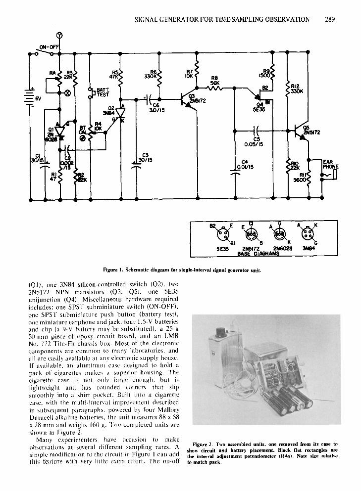
The device is essentially two relaxation -typeoscillators. One. using Q l , generates the inter-pulseinterval: the second. incorporating Q4, generates thesa« tooth waveform that produces the audible tone.Q5 is an emitter-follower necessary to drive thehigh-impedance earphone. The timing is controlledby C I and RA. which represents the total resistancebetween the anode of 0 I and the positive pole of thepower source (+ Veel- RA is a potentiometer whichallows the timing interval to be varied. When thetriggering voltage for Ql is reached by C\.. Qlproduces a pulse that triggers 02 to its conductingstate. Q2 remains in its conducting state until thedischarge current from C3 drops below the holdingcurrent of Q2. When Q2 conducts. C3 and C6 aredischarged and 03 is changed to its nonconductivestate. When Q3 is conductive. 04 will not oscillate.since R8. the timing resistance, is connected to a lowvoltage at the collector of 03. A low current throughR6 holds 03 conductive until C3 discharges throughQ2, When 03 is nonconductive, Q4 oscillates at afrequency determined by R7, R8. and C4. The toneburst duration is determined by the size of C3. Thebattery test switch bypasses 0 l , sending a continuouspulse to Q2 via a voltage-dropping potentiometer.
Components required for each basic unit include:One 47-ohm resistor (R D. three 22K resistors (R2,R3. RIO). one 10K potentiometer (R4), one 47Kresistor m.5). two 330K resistors (R6. R 12). one 10Kresistor (R7), one S6K resistor (R8), one l.SK resistor(R9), one S.6K resistor (Rl l), one 3M potentiometer(RA) (all resistors may be 1/2 or 1/4 W). two30 ~F! 15 V capacitors (C\. C3). one .002-~F
capacitor ((2). one .Ol-f./F capacitor (C4), one .0S-IlFcapacitor (C5). and one 3.0-IlF capacitor (C6). Thesemiconductors required are all listed by GeneralElectric manufacturer's number. Except for the PUT,any similar component may be substituted withacceptable results. The semiconductors required are:one 2N6028 programmable unijunction transistor
288
SIGNAL GENERATOR FORTIME-SAMPLING OBSERVATION 289
ON-
I R63301<
C33011~
R7101< R8
5tiK
C40.01115
RI233Ot<
B2~E
815E36
Figure I. Schematic diagram for single. interval signal generator unit.
(Q I), one 3N84 silicon-controlled switch (Q2), two2N5172 NPN transistors (Q3, Q5), one 5E35unijunction (Q4). Miscellaneous hardware requiredincludes: one SPST subminiature switch (ON-OFF),one SPST subminiature push button (battery test),one miniature earphone and jack, four 1.5-V batteriesand clip (a 9-V battery may be substituted), a 25 x50 111m piece of epoxy circuit board, and an LMBNo. 772 Tite-Fit chassis box. Most of the electroniccomponents are common to many laboratories, andall are easily available at any electronic supply house.If available, an aluminum case designed to hold apack of cigarettes makes a superior housing. Thecigarette case is not only large enough, but islightweight and has rounded corners that slipsmoothly into a shirt pocket. Built into a cigarettecase, with the multi-interval improvement describedin subsequent paragraphs, powered by four MalloryDuracell alkaline batteries, the unit measures 88 x 58x 28 mm and weighs 160 g. Two completed units areshown in Figu re 2.
Many experimenters have occasion to makeobservations at several different sampling rates. Asimple modification to the circuit in Figure I can addthis feature with very little extra effort. The on-off
Figure 2. Two assembled units, one removed from its case toshow circuit and battery placement. Black flat rectangles arethe Interval adjustment potentiometer (RAs). Note size relativeto match pack.

290 AYLWORTH AND STOVALL
Figure 3. Schematic diagram for multiple. interval modification.
,>wi tch is replaced by one set of poles of a live-positiondouble-pole rotary gang switch. Four potentiometers(R~ I, RA2, RAJ, RA4) are connected to weightingre,>l,>tor'> (RH. RC, RD) and substituted for RA inFi~UIT I by means of the second set of poles on therutar~ switch. This substitution is made atconnections "X" and "Y" in Figure 1. Figure 3presents a schematic drawing of this modification. Ofcourse, any number of RAs can be included; however.there is scant room for more than three additionalpotentiometers in the case currently in use. With thismodification. a unit will cost under $10 for parts,
I he PUT has the special function of triggering atan anode potential proportional to the voltage appliedto the gate terminal. This means that it will oscillateaccurately at any voltage from above 9 to below 4.5 V.at a rate determined by the timing R-C circuit. Thus.the preset intervals will remain stable as the batteryvoltage declines with use, The battery test circuitensures both that the battery voltage is high enoughfor accurate operation of the PUT and. indirectly,that sufficient battery life remains for at least I hoperat.ion .. After assembly of the circuit. the batterytest ('IITUIt must be calibrated. A current-limited4.5- \ de power supply should be applied in place of
(Received for publication November 19. 1974;revision received January 17, 1975.)
REYNIERSE. J. H., & TOEVS. J. W. An ideal signal generatorfor time-sampling observation procedures. Behavior ResearchMethods & lnstrumentation, 1973. 5.57·58.
REFERENCE
the battery. the unit turned on, the battery test pushbu lion depressed. and potentiometer R4 adjusteduntil the tone is heard in the earphone. R4 is thenslowly backed offuntil the tone ceases. During normaloperation. a press all the BT button will produce atone if the battery is producing better than 4.5 V.With the low drain of this circuit. the experimentercan be sure that the intervals will be produced withnominal accuracy for at least I h.
The 3M potentiometer (RA) will provide acontinuously adjustable interval of from I to 60 sec.With the resistances specified in Figure 2. a realm ofintervals from I to 60 sec may be preset (RA4 shouldbe set to the shortest interval. RA I to the longest).The nominal replication deviation will be less than20ft) of the repetition interval (about 1.2 sec for al-rnin interval). Intervals longer than 60 sec may beobtained by replacing Cl with up to a 100 J.lF/lS Velectrolytic capacitor. A limit is imposed by leakagefrom CI. and intervals in excess of 3 min are liable tobe highly inaccurate. The tone burst will have afrequency of about 1.5 KHz. The frequency may bevaried throughout a range of from 400 Hz to about10 KHz. by changing R8 and C4. The tone burstduration is presently about. 7 sec. It may be variedfrom about 100 msec to about I sec by changing C3.The circu it has been designed for 6 V. a 9-V batterymay be used. but R5 must be increased, R4 mayrequire adjustment. and 9 V will change thecharacteristics of the tone burst.
As Reynierse and Toevs (1973) assert, these deviceshave many uses in the laboratory. classroom, andindustrial environments. The present circuit has beentested with a continuous operation period of 1.500 h.and used for about 200 additional hours on anintermittent schedule. with its original set of heavyduty batteries. The unit has been found to beinsensitive to temperature variation. remaining highlyaccurate under all conditions of use. As yet. theeffective battery life has not been reached. With themultiple-interval modification, it has been found to beconvenient. rugged. dependable. and versatile. This istruly an "ideal" signal generator for human factorsfield or laboratory investigations.
OFF
RD68K
RA4'/)1001<
r------IIIII,,~
R8330K
RA21M
RAI3M