keysight technologies battery drain analysis for low...
TRANSCRIPT

Keysight TechnologiesBattery Drain Analysis for Low Power IoT Devices
Application Note

02 | Keysight | Battery Drain Analysis for Low Power IoT Devices - Application Note
The Challenge
Low-power devices associated with the Internet of Things (IoT) consume power at highly variable rates, from microseconds to seconds, and from picoamperes to amperes. Accurate battery drain measurements are critical to achieving the long battery life customers expect, and Keysight’s broad range of solutions enable engineers to get convenient, fast and accurate results that properly characterize battery drain on IoT devices.
The Spectrum of Design and Testing NeedsIt is no longer sufficient for an IoT device to last a few years between battery replacements. Customers often expect ten-year battery life in many applications, and some vendors even advertise “leave for life” or “set and forget” devices that last for the application lifetime, often well beyond a decade.
To meet these sorts of expectations, chipset designers design ICs with deep sleep modes that consume very little current. These devices have operation modes with slow clock speeds, reduced instruction sets, low battery voltages, and low current consumption. These applications require testing three to six orders of magnitude of current levels for events lasting microseconds or milliseconds.
To reduce the relatively large power consumption associated with wireless communications, standards groups are defining new low energy operating modes that combine low RF power levels and simple connection protocols that limit active operation time. Wireless module manufacturers extend battery life by designing and testing programs for embedded processors to shorten power-hungry states.
The product designer who integrates sensing, processing, control and communication components into a final product must know how the peripherals behave and consume power. This designer has additional software or firmware control over power supplies, analog and mixed-signal components, and the digital and RF subsystems. As the product goes into production, a simpler set of tests and test equipment can verify proper device operation quickly and inexpensively.
These different needs challenge the engineer to make measurements with widely varying levels of detail at each step of the development process. The chip designer and module designer need very fast evaluation of power consumption in various device operating states. The module designer needs similarly fast measurement over many orders of magnitude on any of several chips, correlated to module firmware operations. The product designer may need slightly less precise time resolution, but must accurately know overall power consumption throughout the hardware and software development process. Finally, the manufacturing test department needs to know the device operates correctly, perhaps using a simpler set of test equipment.
Wearable IoT DevicesSome IoT devices, such as hearing aids, digital eyewear, and fitness trackers, are intended to be worn by the user. Because these devices are often in operational (non-sleep) modes, they tend to have shorter battery lives. A typical block diagram for a wearable fitness tracker is shown below.
Figure 1. Block diagram for a wearable fitness tracker
Wearable fitness devices have sensors and RF components that intermittently measure, store and send data. To optimize the power budget and usability, the design engineer may use a wide variety of instrumentation and software to characterize energy measurements and then tune the CPU firmware to optimize the energy used during each operation. The rest of this document describes five such devices, summarized below (all values approximate).

03 | Keysight | Battery Drain Analysis for Low Power IoT Devices - Application Note
CX33003 SeriesDevice Current Waveform Analyzer
34470A DMM Digitizing
N2820A Scope Probe
N6705B/N6781ADC Power Analyzer
and SMU
B29002
SMUNormal Hi Res
Display Size (diagonal)
4.3” Scope dependent 5.9” 4.3” 14.1”
Bandwidth, Sample Rate
17 kHz,50 kSa/s 500 kHz,5 GSa/s 29 kHz,200 kSa/s 10 kHz,100 kSa/s
140 MHz,1 GSa/s 15 MHz,75 MSa/s
Meas. Resolution 14 bits 14 bits 18 bits 20 bits 14 bits 16 bits
Min Measurable Pulse Width
100 µs 2 µs 25 µs 100 µs 5 ns 50 ns
Min Measurable Static Current4
10 pA 500 nA 800 nA 1 pA 150 pA
Min Measurable Dynamic Current (10 kHz BW)
10 nA 500 nA 2.4 µA 10 fA 150 pA
Max Measurable Current
10 A 5 A 3 A 3 A 50 A
Min/Max Source Current
(none) (none) 3 A 3 A (none)
Burden Voltage5 27 mV 1 mV 0 mV 0 mV 4 mV
Price + ++ ++ ++ ++++
Typical Use R&D / Mfg R&D R&D / Mfg1 R&D R&D
1. Using N6700 frame with N6781A SMU in mfg and N6705A frame with N6781A SMU in R&D2. 1 pA is RMS noise (NBW = 0.1 Hz to 10 Hz).3. 150 pA is RMS noise (NBW = 10 Hz to 20 MHz)4. Accounts for typical noise with 1% error and quasi-DC current measurement5. When measuring 10 mA on appropriate range; the N6781A and B2900 Series both source current, so always 0 mV burden voltage.
Table 1.

04 | Keysight | Battery Drain Analysis for Low Power IoT Devices - Application Note
Table 2.
Instrument Optimization Hints
34470A DMM – Low-cost, readily available tool – High precision up to 7.5 digits – Measures static, low- or high-level currents – Digitize mode useful for capturing waveforms up to 10
kHz at 4.5 digits – Small form factor fits easily into rack
– Avoid fast-changing signals – Use fixed range to avoid measurement discontinuities
N2820A Current Probe
– High sensitivity – High dynamic range – Excellent bandwidth for fast-changing signals up to 3
MHz – Works with many readily available oscilloscopes – Very flexible triggering model
– Amplitude resolution depends on oscilloscope – Keep leads short for optimal bandwidth
B2900 Series SMU – Lowest range has resolution down to 10 fA; highest range measures up to 10 A
– Built in source means: – Zero burden voltage – No droop – Simplified wiring
– Small form factor fits easily into rack – Quick I/V Measurement Software provides measure-
ment insights
– Avoid fast-changing signals – Use fixed range to avoid measurement discontinuities – Capital purchase
N6705B DC Power Analyzer + N6781A SMU
– Seamless ranging; can measure nA to A in a single pass
– Built in source means: – Zero burden voltage – No droop – Simplified wiring
– Can simulate battery behavior – Plug in modules allow customization for multiple
applications – Can re-use modules and programs in manufacturing
with N6700 mainframe – Optional 14585 software shows CCDF and other
information to enhance insights
– Larger form factor requires more rack space – Capital purchase
CX3300 Series Device Current Waveform Analyzer
– Purpose-built for measuring dynamic current signals up to 140 MHz (includes probe BW), 14 or 16 bits
– Displays waveform features that were never visible before
– Unmatched performance—measures fast signals, low to high currents
– Integrated measurement categories: time, current levels, area, CCDF, and much more
– Automatic current and power profiler provides detailed power budget information
– Huge display gives excellent usability, but requires morerack space
– Capital purchase – Keep leads short for optimal bandwidth
05 | Keysight | Battery Drain Analysis for Low Power IoT Devices - Application Note
Truevolt 34470A DMM
Precise current measurement and high-speed digitization give you good waveform insights from a relatively simple tool that is probably already on your bench.
The product designer may be able to perform basic current measurements with an instrument already on the bench: a digital multimeter (DMM). For example, the Keysight 34470A DMM can measure current with precision (down to 10 pA accuracy) and digitize at high rates (up to 50,000 readings per second, or 20 μs per reading). As an integrating DMM, it can measure current consumption precisely over various time spans. With the device under test (DUT) in a steady state condition, the DMM can measure the current (or voltage) in a circuit with high resolution using normal modes and selectable integration times, yielding seven orders of magnitude resolution from ranges down to 1 μA full scale.
In digitizing mode, the 34470A can sample current at high rates and generate numerical or graphical results for analysis of waveform features. The 34470A can manage high common mode voltages and brief, high-current transients. This allows the user to measure circuits without ground reference and to zoom in on low current states and still make accurate sleep mode measurements.
Figure 2. Keysight Truevolt 34470A DMM
Figure 3. Digitized current waveform of wearable fitness monitor shown on display of Keysight 34470A DMM.
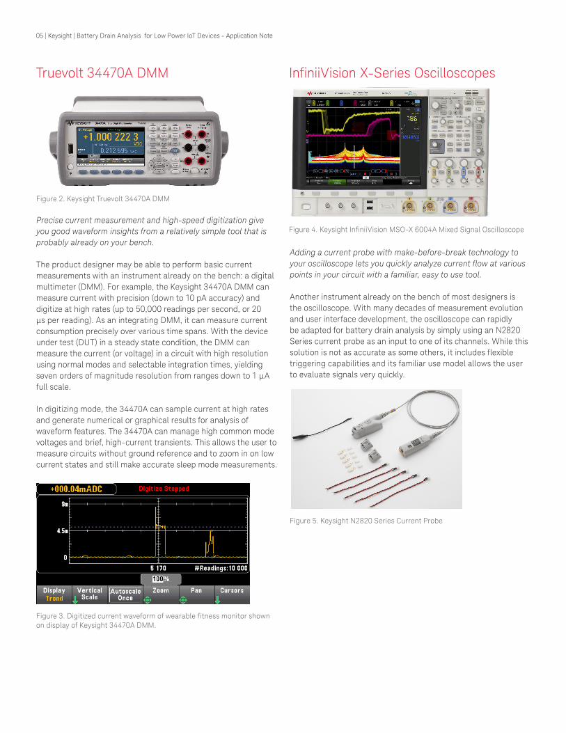
InfiniiVision X-Series Oscilloscopes
Figure 4. Keysight InfiniiVision MSO-X 6004A Mixed Signal Oscilloscope
Adding a current probe with make-before-break technology to your oscilloscope lets you quickly analyze current flow at various points in your circuit with a familiar, easy to use tool.
Another instrument already on the bench of most designers is the oscilloscope. With many decades of measurement evolution and user interface development, the oscilloscope can rapidly be adapted for battery drain analysis by simply using an N2820 Series current probe as an input to one of its channels. While this solution is not as accurate as some others, it includes flexible triggering capabilities and its familiar use model allows the user to evaluate signals very quickly.
Figure 5. Keysight N2820 Series Current Probe

06 | Keysight | Battery Drain Analysis for Low Power IoT Devices - Application Note
The Keysight N2820A High Sensitivity current probes can measure current consumption of battery powered devices or individual circuits. Oscilloscopes using the N2820A offer higher bandwidth than many other instruments, in this case 500 kHz to 3 MHz of bandwidth, at 20,000:1 dynamic range. The N2820A’s special “make before break” connectors allow the user to rapidly move around the circuit while it is active, characterizing the behavior of various circuit nodes.
Figure 6. N2824A connected to a PCBA
If the probes are used on mixed signal oscilloscopes (MSOs) with digital pattern inputs, circuit behavior can quickly be correlated to control states and the processor instructions that cause the circuit behaviors. This allows product firmware engineers to directly measure the effects of software or firmware changes on power consumption.
Figure 7. Oscilloscope trace of IoT device charge behavior. Note the presence of high and low currents with high rates of change.
N6705B DC Power Analyzer and N6781A Source / Measure Unit (SMU)
A single instrument for sourcing and measuring current that lets you get insight into your signal quickly and then move your test program into production with the same SMU module.
The SMU is an intelligent power supply that can deliver power to the DUT while measuring current consumption and evaluating the results, including battery drain analysis. The Keysight N6705B with the N6781A SMU module is such a device. The power supply can simulate dynamic conditions including power sequencing, battery droop and various supply variations. Because it supplies the power, it can measure it both accurately (0.025% up to 18 bits) and quickly (100 kHz). The N6705B can behave like an oscilloscope so the designer has a familiar operating model to rapidly explore circuit behavior. It can also behave like a data logger to record long term circuit power consumption.
The N6781A SMU has glitch-free sourcing and measurement due to its seamless ranging across four current measurement ranges. It can perform as a voltage or current source or as a constant voltage (CV) or constant current (CC) electronic load with excellent transient response that delivers stable output during high-speed load changes.
Software packages, such as the Keysight 14585A Control and Analysis Software, can add additional capabilities to the designer’s toolkit, allowing fast connection setup and measurement of the device’s most important characteristics. For example, the 14585A software can perform a complementary cumulative distribution function (CCDF) analysis, which concisely displays short- and long-term battery drain measurement.
Following design verification, you can move the SMU module and its SCPI programs into the factory and become part of the manufacturing test setup.
Figure 8. Keysight N6705B DC Power Analyzer

07 | Keysight | Battery Drain Analysis for Low Power IoT Devices - Application Note
B2900 Series Precision Source / Mea-sure Units
Figure 9. Keysight B2912A Precision Source/Measure Unit (SMU)
A single instrument for sourcing and measuring low voltage and current with great precision and accuracy that can be used on the bench or in a production test rack.
The Keysight B2900 Series Precision Source / Measure Units combine cost-effective precision measurement with a best in- class graphical user interface (GUI) to give designers deep insight into their applications. A two-channel B2900 reduces wiring complexity, as it replaces two DC voltage sources and two DMMs.
These SMUs have excellent precision (minimum 10 fA/100 nV sourcing and measuring resolution), and the color LCD display features several task-based viewing modes that dramatically improve productivity for test, debug and characterization. The design or validation engineer can also develop tests using the SCPI programming language, which can then be re-used if the B2900 SMU is integrated into production test systems. The instrument also has a limit test feature that lets the instrument make automatic pass/fail judgments in production test without the need to write a PCbased test program.
Beyond SCPI, the B2900 Series has several remote control options that are available at little or no cost: BenchVue, B2900A Graphical Web Interface, B2900A Quick IV Measurement Software, and EasyEXPERT group+. In particular, the B2900A Quick IV Measurement Software lets you quickly configure and perform IV measurements and display the results in tables and graphs without programming.
Figure 10. Keysight B2900A Quick IV Measurement Software
CX3300 Series
Figure 11. Keysight CX3324A Device Current Waveform Analyzer
An easy-to-use instrument with extraordinary accuracy and “Anywhere” zoom that lets you see waveform details you’ve never seen before; includes automatic current and waveform profiling for fast insight into your battery drain budget.
A device current waveform analyzer is a new class of instrument that is especially useful to designers of low power IoT devices. The Keysight CX3300 Series provides the most detailed views, in both amplitude (100 nA to 10 A) and time (140-MHz bandwidth and up to 1-GHz sampling rate) of any current measurement instrument on the market. These detailed views let you precisely view low-level current waveforms that were previously undetectable.
Figure 12. See waveform details that were previously hidden

08 | Keysight | Battery Drain Analysis for Low Power IoT Devices - Application Note
The CX3300’s large display and multi-touch oscilloscope use model make it easy to capture, examine, and measure high resolution current waveforms at the circuit, sub-circuit, or chip level. The instrument’s “Anywhere” zoom function lets you quickly expand any current waveform segment in both X and Y to see greater detail.
Figure 13. The “Anywhere” zoom function expands the area within the yellow rectangle in both X and Y, showing detailed waveform information.
Powerful analysis functions in the CX3300’s Automatic Current and Power Profiler display the measurements not only in time and current, but also total charge consumed in microcoulombs (μC).
Figure 14. The Automatic Current and Power Profiler breaks up a waveform into segments and provides detailed analysis of current and power consumption for each segment.
The CX3300’s optional digital input channels (CX1152A) allow a chip programmer to immediately see the effects of device programming changes on battery power. These digital channels are useful when you need to synch current measurements with digital signals, such as the IoT device’s controller I/O or data bus.
The digital channel runs at up to 0.5 GSa/s and supports a maximum record length of 512 Mpts. Unlike conventional digital probes, each CX1152A probe has 10 MΩ input resistance, which minimizes load current to enable accurate low power measurements.
Figure 15. Optional CX1152A digital input channels for Keysight CX3300
This combination of high precision measurements with ease of use speeds time to market for products with optimal battery life, even when the timescale being measured is in nanoseconds.
Figure 16. A 20-ns pulse, clearly visible on the CX3300 display
Conclusion
The devices that will fuel the rapid growth of the IoT over the next few years are on the drawing boards now. As consumer, industrial, and medical customers demand ever-longer battery life from IoT devices, designers and manufacturers need insight into their device’s complex battery consumption waveforms to innovate new ways to extend battery life. Only Keysight offers this broad variety of instruments and software to meet the needs of IoT designers, from chip design and test, RF module performance evaluation and test, to final product manufacturing test, with the measurement confidence that comes only from Keysight.

09 | Keysight | M9037A PXIe Embedded Controller - Data Sheet
This information is subject to change without notice.© Keysight Technologies, 2017Published in USA, December 1, 20175992-1765ENwww.keysight.com
www.keysight.com/find/iot-lowpower
For more information on Keysight Technologies’ products, applications or services, please contact your local Keysight office. The complete list is available at:www.keysight.com/find/contactus
Americas Canada (877) 894 4414Brazil 55 11 3351 7010Mexico 001 800 254 2440United States (800) 829 4444
Asia PacificAustralia 1 800 629 485China 800 810 0189Hong Kong 800 938 693India 1 800 11 2626Japan 0120 (421) 345Korea 080 769 0800Malaysia 1 800 888 848Singapore 1 800 375 8100Taiwan 0800 047 866Other AP Countries (65) 6375 8100
Europe & Middle EastAustria 0800 001122Belgium 0800 58580Finland 0800 523252France 0805 980333Germany 0800 6270999Ireland 1800 832700Israel 1 809 343051Italy 800 599100Luxembourg +32 800 58580Netherlands 0800 0233200Russia 8800 5009286Spain 800 000154Sweden 0200 882255Switzerland 0800 805353
Opt. 1 (DE)Opt. 2 (FR)Opt. 3 (IT)
United Kingdom 0800 0260637
For other unlisted countries:www.keysight.com/find/contactus(BP-9-7-17)
DEKRA CertifiedISO9001 Quality Management System
www.keysight.com/go/qualityKeysight Technologies, Inc.DEKRA Certified ISO 9001:2015Quality Management System
Evolving Since 1939Our unique combination of hardware, software, services, and people can help you reach your next breakthrough. We are unlocking the future of technology. From Hewlett-Packard to Agilent to Keysight.
myKeysightwww.keysight.com/find/mykeysightA personalized view into the information most relevant to you.
http://www.keysight.com/find/emt_product_registrationRegister your products to get up-to-date product information and find warranty information.
Keysight Serviceswww.keysight.com/find/serviceKeysight Services can help from acquisition to renewal across your instrument’s lifecycle. Our comprehensive service offerings—one-stop calibration, repair, asset management, technology refresh, consulting, training and more—helps you improve product quality and lower costs.
Keysight Assurance Planswww.keysight.com/find/AssurancePlansUp to ten years of protection and no budgetary surprises to ensure your instruments are operating to specification, so you can rely on accurate measurements.
Keysight Channel Partnerswww.keysight.com/find/channelpartnersGet the best of both worlds: Keysight’s measurement expertise and product breadth, combined with channel partner convenience.