a journey of wall control improvement at boddington gold paper presents a case study of...
TRANSCRIPT
APSSIM 2016 – PM Dight (ed.) © 2016 Australian Centre for Geomechanics, Perth, ISBN 978-0-9924810-5-6
APSSIM 2016, Brisbane, Australia 407
A journey of wall control improvement at Boddington Gold
CC Graf Newmont Mining Corporation, Australia
R Sullivan Newmont Mining Corporation, Australia
Abstract Pit slope optimisation and the implementation of effective wall control techniques are a valuable aspect of the mining process. The objective of pit slope optimisation programs during mining operations is twofold; to develop safe operating conditions, and to minimise waste stripping ratios (O’Bryan 2013). By achieving these two aims, the pit slope angle can be maximised, and in turn can have a significant impact to the economics of an open pit operation.
The Boddington gold-copper mine is owned and operated by Newmont Mining Corporation. Located approximately 130 km southeast of Perth in Western Australia, the Boddington operations commenced mining in 2007 with production from two large open pits utilising large-scale non-selective open pit mining methods. Situated within the Saddleback Greenstone Belt, the pits are being developed in a largely hard rock environment of good to very good rock mass quality.
The pit slope configuration at Boddington has experienced a number of changes since the commencement of operations. Initial design recommendations indicated hard rock slopes could be constructed at an inter-ramp angle of 64 degrees. This slope design is steep by industry standards. A challenge of the hard rock slopes at Boddington has been the inability to consistently achieve the required catch berm width to retain rockfall. This challenge has resulted in safety and economic value impacts including large areas of remedial work in operational areas, and step-ins to develop rockfall protection not provided by catch berms. As a result the inter-ramp angle was reduced to 59 degrees.
To enable the consideration of steepening the inter-ramp angle above 59 degrees four key elements are required to be achieved; ongoing structural modelling and interpretation, consistent attainment of the designed wall configuration, blast designs achieving high quality batter conditions, and analysis showing proposed angles falling within stability acceptance criteria. Numerous trials have been completed, with the most significant in late 2013. This trial increased the batter height from 24 to 36 metres, and implemented crest scaling techniques and free faced trim blasts. Through the ongoing use and refinement of these techniques, and close collaboration between technical and operational teams, significant improvements have been made in reducing crest loss and improving batter conditions. Results have enabled wall-steepening trials to be implemented in late 2015.
This paper presents a case study of Boddington’s journey to create a repeatable wall control technique to enable the consistent attainment of the wall configuration, and achieve high quality batter conditions.
1 Introduction Newmont Boddington Gold (Boddington) is located approximately 130 km southeast of Perth in Western Australia. The mine commenced mining operations in 2007 with production from two large open pits, North Pit and South Pit. The Boddington deposit is a large tonnage, low grade, gold-copper ore body utilising large-scale non-selective open pit mining methods. The annual production rate is approximately 80 million tonnes per annum (ore and waste), producing 794,000 ounces of gold and 79 million pounds of copper.
The two pits are being developed in a largely hard rock environment of good to very good rock mass quality with relatively low stresses. Initial design recommendations indicated hard rock slopes could be
https://papers.acg.uwa.edu.au/p/1604_25_Graf/
A journey of wall control improvement at Boddington Gold CC Graf and R Sullivan
408 APSSIM 2016, Brisbane, Australia
constructed at an inter-ramp angle of 64 degrees. Experience has shown an inability to consistently achieve the required catch berm width to retain rockfall. This has resulted in safety and value impacts. The pit slope configuration at Boddington has experienced a number of changes since the commencement of operations, and the current inter-ramp angle is 59 degrees.
Even a slight increase in inter-ramp angle can have a significant impact to the economics of an operation. To address the loss of catch berm capacity and poor batter conditions, Boddington has taken an approach to wall design that aims to increase the design catch berm width, whilst simultaneously focussing on achieving an average crest loss of below 3 m.
2 Geotechnical environment
2.1 Geology Boddington is located within the Saddleback Greenstone Belt, a northwest trending fault approximately 45 km long and 7 km wide. The belt is steeply dipping and has been intruded by quartz diorite and post mineralisation dolerite dykes.
Lithology at Boddington comprises two main rock types, andesite and diorite, intruded by sub-vertical dolerite dykes and sub-horizontal (15 to 30 degree) dolerite sills. The contact between andesite and diorite is gradational, but forms a sharp contact with dolerite. The sub-vertical dolerite dykes are generally north–south and northwest–southeast trending. Foliation is indistinct or weakly developed, except in the western area of North Pit where it can be moderate to strong with a sub-vertical or steeply dipping orientation.
2.2 Geotechnical conditions The North Pit and South Pit are being developed in hard rock andesite and diorite intruded by dolerite dykes. A saprolite/oxide zone comprising highly weathered rock, residual soil and bauxitic laterite on top overlies the hard rock. The contact between the hard rock and saprolite/oxide is mostly sharp, but transition zones of 5 to 25 m thick exist in areas.
The andesite and diorite are defined as a strong to very strong rock mass with a wide range of unconfined compressive strength (UCS) from 100 to 200 MPa whilst the dolerite is predominantly very strong with a UCS ranging from 200 to 300 MPa. The average bulk density of andesite and diorite is 2.75 t/m3 whereas dolerite has higher density of 3.00 t/m3.
The rock quality designation (RQD), (Deere et al. 1967) in the hard rock is relatively high, ranging between 90 to 100% except in the transition zone where the RQD varies from 40 to 90%. The drill core data suggests that the fracture frequency decreases with depth and rock mass quality becomes excellent from approximately 300 m below surface and then remains constant through the lower levels.
At Boddington there is limited ability to identify adversely oriented faults before they are encountered during mining. The known major structures are not adversely oriented with respect to slope stability, but past discovery of major structures during mining is cause to remain vigilant, and there is potential risk associated with intermediate scale structures.
A network of incipient defects exists in the high wall rock masses. These defects have a wide range of orientations, and tend to open due to blasting and/or mining-induced stress changes. The dolerite commonly includes orthogonal joint sets, resulting in blocky ground conditions. The presence of geological structures in some areas where the geometry is unfavourable can contribute to loss of catch berm widths.
Joint surfaces are predominantly undulating rough with friction angle varying from 40 to 50 degrees, but undulating and planar smooth fractures sometimes exist with friction angle of 30 to 40 degrees with residual cohesion of 0 kPa.
A compartmentalised hydrological regime has resulted in dewatering difficulties. The drill and blast process is affected by the presence of the compartmentalised water at most mining levels.
Monitoring slopes and rockfalls
APSSIM 2016, Brisbane, Australia 409
3 Pit slope design philosophy Pit slope optimisation during mining operations is a valuable aspect of the mining process. The objective of pit slope optimisation is twofold (O’Bryan 2013):
1. To develop and maintain a safe access and safe operating conditions.
2. To minimise waste stripping requirements by maximising wall angles.
Mine design is an iterative process as factors may be revised and updated during the mine life. A large component of the operational performance of a hard rock pit slope is reliant on effective wall control techniques — drilling, blasting, scaling. The aim of wall control blasting is to minimise disturbance to the rock mass beyond the design excavation boundary, whilst meeting requirements of fragmentation and dig-ability. The wall above becomes a legacy; therefore it must also last the life of the mine in relatively the same condition.
The Boddington ultimate pit design is based on a series of cut backs or pit phases. This phased approach allows pit wall design criteria to be refined based on the measured operational performance, for example crest loss and toe achievement. To enable the consideration of steepening the inter-ramp angle of the ultimate pit design above 59 degrees four key elements were targeted:
1. Consistent attainment of the designed wall configuration with minimum loss of effective catch berm width.
2. Blast designs ensuring consistent, high quality batter conditions.
3. Structural modelling and interpretation be kept up-to-date and undergo continual review. Major structures that could cause large scale failure to be well delineated, and intermediate and minor structures be considered with respect to scaling and ground support.
4. Analysis showing proposed angles will fall within stability acceptance criteria.
Implicit in the design approach is the commitment to continuous improvement, and ongoing internal and external peer review of both the design process and operating considerations.
4 Evolution of hard rock slope configurations 2008 to 2013 The hard rock slope design at Boddington is controlled by rockfall and structure (kinematics). Rock mass stability assessments for hard rock slopes at Boddington have been undertaken several times by external consultants and internally. Results from all of these studies indicated that a stress induced failure mechanism through the rock mass is unlikely to occur. Slope performance experience since 2007 has supported the analysis results.
The hard rock slopes at Boddington have undergone a number of design and wall control changes since feasibility recommendations in 2005. Changes have aimed to meet required considerations of (Lorig et al. 2009):
• Containing 70–85% of a potential bench scale failure volume.
• Rockfall catchment.
• 80% of catch berms achieving the design width.
The evolution of the hard rock slope configurations is summarised below and in Table 1.

A journey of wall control improvement at Boddington Gold CC Graf and R Sullivan
410 APSSIM 2016, Brisbane, Australia
Table 1 Evolution of hard rock configurations between 2008 and 2013
2008 2010 2012 2013
Batter height (m) 36 24 24 36
Bench height (m) 12 12 12 12
Lower bench (m)
Stack 1 1 1 2
Angle (degrees)
85 90 90 90
Upper bench (m)
Stack 2 1 1 1
Angle (degrees)
85 90 70 70
Drill step-in (m) 1.7 N/A 1.7 1.7
Berm width (m) 12 14.5 8.3 15.2
Inter-ramp slope angle (degrees)
64 59 59 59
Pre-split configuration 3 × 12 m Single 24 m 12 m 70 degree 12 m vertical
12 m 70 degree 12 m vertical
Wall blast configuration Combined production and
trim
Combined production and
trim
Combined production and
trim
Free faced trim upper bench only
Blast loading methods Emulsion based, internally cord
traced packaged pre-split
explosives
Emulsion based, internally cord
traced packaged pre-split
explosives
Watergel based, internally cord
traced packaged pre-split
explosives
Watergel based, internally cord
traced packaged pre-split
explosives
The 2005 feasibility study recommended triple stacked 12 m benches with 85 degree batters and 12 m catch berms. Initial wall control programs in 2008 focussed on development of an effective pre-split. Experience showed that achievement of the 36 m batter configuration was unlikely to be practicable due to crest loss of up to 8 m, resulting in 4 m of effective berm width.
A changed wall configuration using a double bench of 24 m, 90 degree batter and 14.5 m berm width was implemented in 2010. Vertical batters were found to be causing significant crest damage of 6 to 8 m. While the configuration was more practicable, the inter-ramp angle had been decreased to 59 degrees, resulting in significant economic impact. The desired batter conditions and rockfall catchment were also still not being achieved. Two main issues were identified with the results:
1. Crest damage was the primary source of loose rocks, and thus rockfall. Improving crest results would therefore reduce occurrence of rockfall.
2. Required catch berm width to retain rockfall was not being achieved due to crest loss. Improving crest loss results would widen the catch berm and increase effectiveness to retain rockfall.
A crest loss of less than 3 m was targeted. Multiple projects were undertaken to optimise wall control drill and blast parameters including differing pre-split lengths, trim blasts, combined production and trim blasts, decoupled pre-split, bulk explosives, and detonation methods.
A benchmarking study was completed in 2011. The study involved 14 mines, seven with batter angles of 85 degrees or greater. The study suggested vertical walls were synonymous with crest damage, with
Monitoring slopes and rockfalls
APSSIM 2016, Brisbane, Australia 411
average loss in the range of 4 to 5 m. It was determined that vertical walls would not achieve the targeted crest loss, and a 70 degree batter would increase the likelihood of achievement.
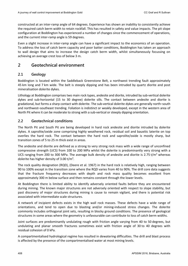
In 2012 the batter configuration was changed to a double bench of 24 m, comprised of a 70 degree batter for the top bench, followed by a 90 degree bottom bench. The catch berm width was reduced to 8.3 m to maintain a 59 degree inter-ramp angle. This batter configuration maximises berm width whilst maintaining the inter-ramp angle. The 2012 slope design is shown in Figure 1.
Figure 1 Section view of the bench configuration used in 2012, 24 m bench configuration mined in 12 m
benches
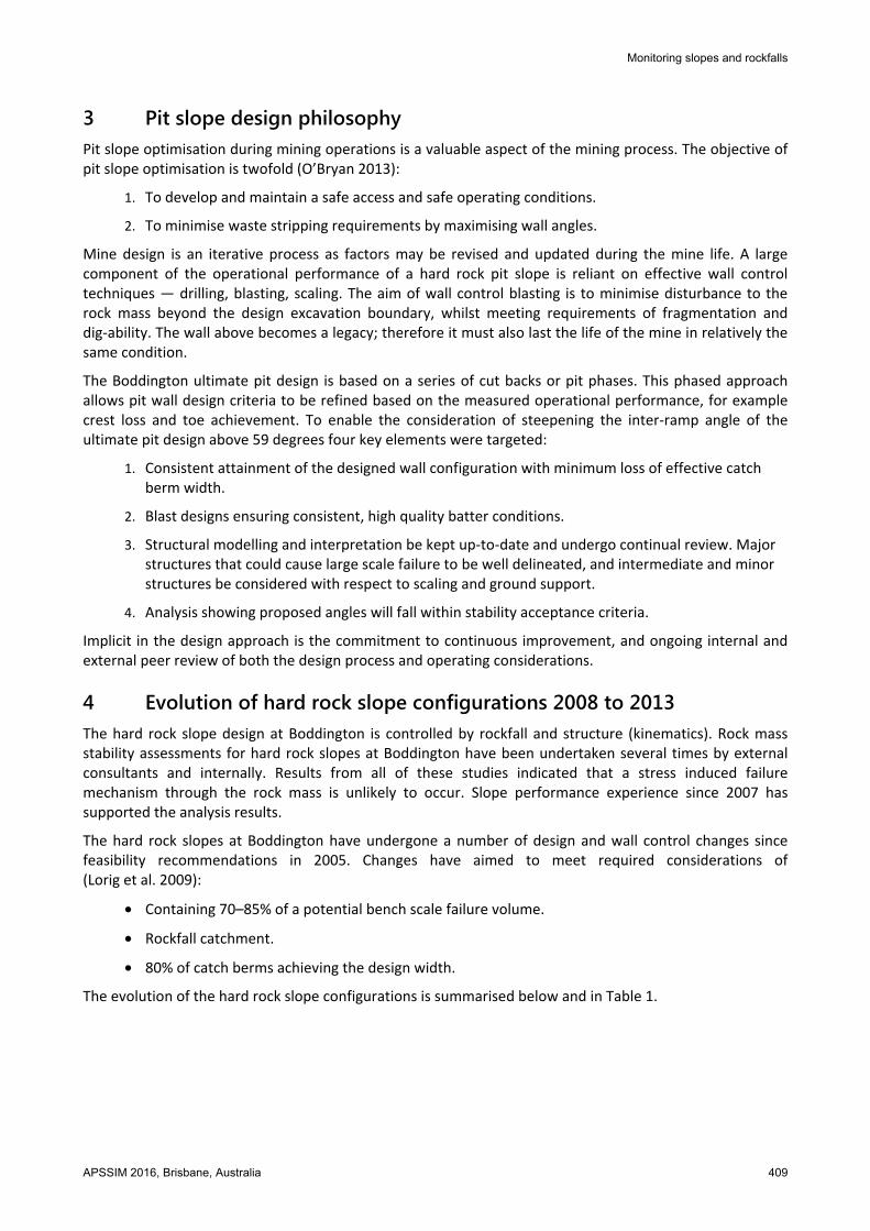
The 2012 configuration successfully reduced the crest loss experienced to an average slightly exceeding 4 m and improved batter face condition. However, with 4 m of crest loss the width of the catch berm was reduced to 4 m, a point where it could no longer retain rockfall and created ‘ski jumps’. A photograph depicting crest loss experienced is shown in Figure 2.
Figure 2 Photograph showing an area of significant crest loss of up to 8 m
To address the loss of catch berm capacity, Boddington took an approach to wall design that aimed to increase the design catch berm width to accommodate a crest loss of 4 m whilst maintaining an inter-ramp angle of 59 degrees. Simultaneously, the operational focus was toward achieving an average crest loss of below 3 m.

A journey of wall control improvement at Boddington Gold CC Graf and R Sullivan
412 APSSIM 2016, Brisbane, Australia
To meet the wall design requirement a change in batter configuration was required. The improved batter conditions allowed for a 36 m bench configuration mined in three 12 m benches to be proposed in late 2013. The first batter face mined at 70 degrees, and the middle and bottom batters mined with a single vertical pre-split. The bench configuration is shown in Figure 3. To maintain an inter-ramp angle of 59 degrees, the design berm width was increased to 15.2 m. This design provided adequate rockfall catch capacity assuming 4 m of crest loss, and catch berm width determined by historical rockfall performance, rockfall analysis, and modified Richie formulae (Ryan & Pryor 2000). The modified Ritchie criterion is commonly applied in the mining industry to calculate the required berm width.
Figure 3 Section view of the 36 m bench configuration implemented in late 2013
5 Key observations of a 70 degree batter In 2011 it was realised that further changes to drill and blast design would be unlikely to yield the desired results for crest damage and berm width, and the bench configuration was changed in 2012 to a 70 degree upper batter. The following observations of the 70 degree batter are made:
• A 70 degree batter on only the upper bench allows a steeper inter-ramp angle to be designed; for example a 24 m bench at 70 degrees and 8.3 m catch berm results in an inter-ramp angle of 54 degrees, by increasing the lower bench to 90 degrees a 59 degree inter-ramp angle is possible.
• The 70 degree batter improved crest retention by an average of 2 m, and also the batter conditions. Due to improved batter face conditions, scaling of the face was approximately 50% faster in comparison to vertical pre-split, resulting in a comparative reduction in cost.

Monitoring slopes and rockfalls
APSSIM 2016, Brisbane, Australia 413
• Heave and breakage of the pre-split was predominantly toward the ‘pit’ side of the pre-split with much less swell or damage visible on the ‘catch berm’ side. Compare this to vertical pre-split where the heave and breakage was equal on both sides.
• The transition between the 70 degree upper bench and vertical middle bench is a critical area in the mitigation of rockfall projection. The transition area can result in a ‘ski-jump’ for rocks falling from above, and a source of rockfall if not properly scaled. A crucial dimension is the step out at the base of the 70 degree pre-split in order to collar the vertical 12 m pre-split. This distance is dependent on type of drill rig; the bigger the distance, the greater the potential interruption between the upper and lower bench. Additional sub-drill is required on the upper bench pre-split (Figure 4).
Figure 4 A crucial aspect of the 70 degree bench configuration is the transition between the upper and
lower bench
6 Implementation of free faced trims for wall control improvement In late 2013, it was recognised that wall control blasting techniques were contributing to crest loss and rough batter conditions, and that a change needed to occur. A cumulative frequency analysis (CFA) completed in 2014 confirmed these observations. The results showed that the actual crest back-break was consistently greater than the back-break indicated by analysis. This suggested the existence of separate operational and geotechnical components to the back-break, with the operational component related to blasting and scaling. Whilst the split between the components is a matter of interpretation it provided a basis for targeting and influencing change in wall control.
6.1 Investigation of wall control blast performance A detailed wall control blast design evaluation was completed in 2013; the evaluation focussed on crest performance. The primary damage mechanism was found to be block heave. Block heave can occur for two reasons; insufficient horizontal relief away from the wall, and/or too much energy adjacent to the batter.
A secondary cause of crest loss was identified as crushing caused by sub-drill damage from the bench above. A designed vertical stand-off of 0 m from the crest was already in place, however it was identified berms were not completely excavated with average depth above grade of 0.8 m, and depth of broken material estimated to be 1.6 m.
It was proposed to introduce free faced trim blasts, verify accuracy of field implementation, and excavate the berm to grade. Free faced trims were a marked change from the traditional wall control blast approach at Boddington. Between 2008 and 2012 Boddington had historically focussed only on perimeter control, for example a pre-split, and the firing of combined trim and production blasts directly adjacent to the high wall. This approach had been preferred as it led to efficiencies in the mining production cycle.
A journey of wall control improvement at Boddington Gold CC Graf and R Sullivan
414 APSSIM 2016, Brisbane, Australia
6.2 Operational implementation In order to reduce the average crest loss to below 3 m, a ‘back to basics’ tactic was adopted. The specific aspects of the trial included:
1. Defining the bench crest: Delineating the limit of the crest ahead of the shovel and excavator using trenching techniques, and exercising a high level of control to minimise over-digging of the crest.
2. Free faced trim blasts: Creating a wall control blast adjacent to the crest position. Providing a free face for material movement and reducing damage into the wall.
The identified opportunities of the approach included:
• Increasing catch capacity and reducing potential ‘ski jumps’ for rockfall projection.
• Clarifying the limit to which the shovel or excavator operator can dig.
• Reducing the time taken to scale the batter face.
• Reducing ground engaging tools machine wear and tear, and bucket and boom damage.
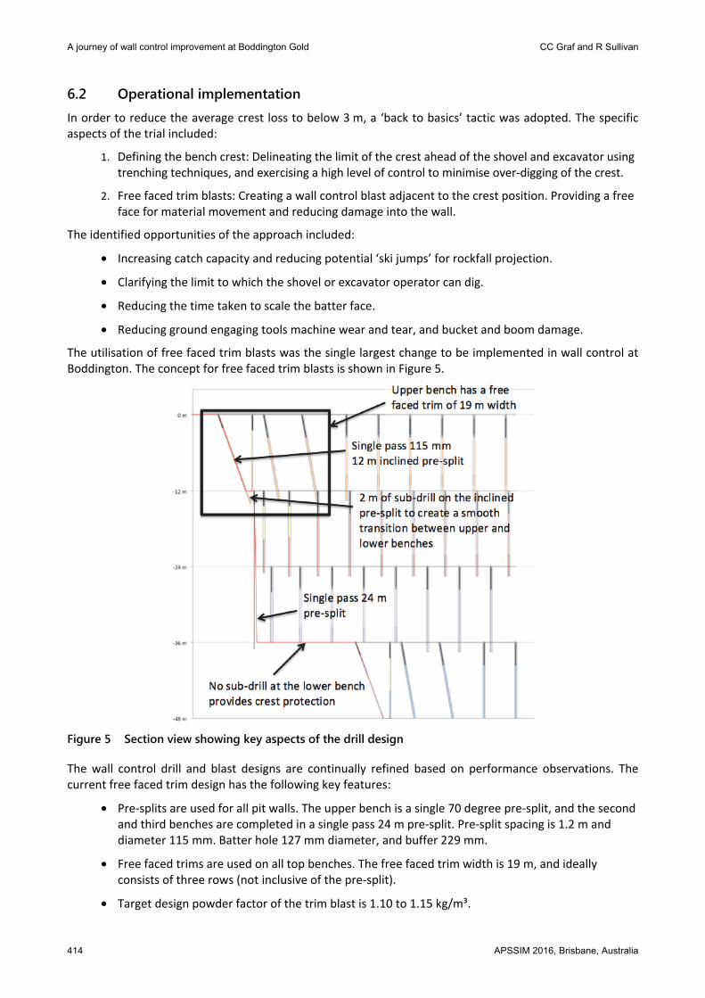
The utilisation of free faced trim blasts was the single largest change to be implemented in wall control at Boddington. The concept for free faced trim blasts is shown in Figure 5.
Figure 5 Section view showing key aspects of the drill design
The wall control drill and blast designs are continually refined based on performance observations. The current free faced trim design has the following key features:
• Pre-splits are used for all pit walls. The upper bench is a single 70 degree pre-split, and the second and third benches are completed in a single pass 24 m pre-split. Pre-split spacing is 1.2 m and diameter 115 mm. Batter hole 127 mm diameter, and buffer 229 mm.
• Free faced trims are used on all top benches. The free faced trim width is 19 m, and ideally consists of three rows (not inclusive of the pre-split).
• Target design powder factor of the trim blast is 1.10 to 1.15 kg/m³.

Monitoring slopes and rockfalls
APSSIM 2016, Brisbane, Australia 415
Free faced trim preparation is critical to success. The key elements of free faced trims at Boddington are a steep face angle, face dug back to hard with no more than 2 m of material left at the toe, and a sharp crest line. Surveys are regularly completed to ensure grade has been achieved.
As refinements to free faced trim blasting led to improvements in batter face conditions and reductions in crest loss, crest chaining was implemented and crest definition used only in limited areas.
7 Evaluation of free faced trim implementation The performance of existing slopes is an important aspect to assess the success of the slope design implementation. One component of slope geometry is the effective catch berm capacity that determines the capability of the berms to contain rockfall. The effective catch berm capacity is affected by three components; crest loss, toe flare, and bench relative level.
7.1 Crest loss results Crest loss is the distance measured between actual and design crest line. Due to differences in the actual and design bench heights, the designed pre-split collar was used as a baseline for measurements. Crest loss at Boddington is measured by creating section lines at 5 m intervals perpendicular to the design crest line. The crest loss results for North Pit and South Pit are summarised in Table 2, and shown in Figure 6.
Figure 6 South Pit crest loss distribution results are shown in histogram and plan view. In plan view
catch berms are colour coded by the achieved crest loss

A journey of wall control improvement at Boddington Gold CC Graf and R Sullivan
416 APSSIM 2016, Brisbane, Australia
Table 2 Summary of crest loss distribution in different rock types in the North Pit and South Pit
Location Overall Andesite and diorite Large vertical dolerite
Average (m)
80% passing(m)
Average(m)
80% passing(m)
Average (m)
80% passing (m)
North Pit 3.4 4.9 2.4 3.3 4.3 5.7
South Pit 2.4 3.4 2.3 3.1 3.2 5.1
Crest loss results indicate:
• Crest loss on a 70 degree batter has been reduced from an average of over 4 m (pre-2014) to an average of 2.4 m in South Pit and 3.4 m in North Pit. The higher result in North Pit is due to the influence of the dolerite. Within the andesite/diorite host rock, North Pit crest loss is 2.4 m.
• Andesite and diorite provide generally consistent results in both the South Pit and North Pit with 80% of catch berms passing the required width.
• Crest loss results in large vertical dolerites are not consistent; crest loss ranges from 0.1 to 8.7 m.
• Significant crest loss occurs above the sub-horizontal dolerite; approximately 87% of catch berms may be expected to be less than the required catch berm width.
7.2 Toe flare results Toe flare is the distance between actual and design toe lines. Similar to crest loss, toe flare is measured by creating section lines at 5 m intervals perpendicular to the design toe line. For the purposes of consistency, toe flare measurement is reported for areas where crest loss measurements were completed. Toe flare results indicate:
• Average toe flare in the South Pit is 1.1 m and in North Pit 0.4 m.
• There is not a significant difference between toe flare achieved in dolerite and andesite/diorite in the South Pit, and likewise the North Pit.
• The upper most bench average toe flare is 0.5 m, and subsequent benches 1 m, and 1.9 m respectively. Field observations indicate the pre-split half barrels are visible to floor in most areas. A review of the toe flare measurements indicates that this could be a product of pre-split drill length. Average toe flare for a 12 m 70 degree pre-split is 0.5 m, for a 12 m vertical pre-split is 0.8 m, and for a 24 m pre-split is 1.7 m.
7.3 Batter condition results General observations of the 36 m bench batter conditions are outlined in the following sections. A wall control evaluation sheet is also completed for each bench mined. The aim of the wall control evaluation is to provide a summary of information that is used to document observations, and refine drill and blast parameters for subsequent benches and blast domains. The key aspects that are included in the evaluation are a location map, cross section depicting actual to design profile, crest loss distribution, photographs, observations and recommendations. An example is shown in Figure 7.

Monitoring slopes and rockfalls
APSSIM 2016, Brisbane, Australia 417
Figure 7 An example of a wall control evaluation sheet
7.3.1 Crest and batter conditions
During the initial stages of the 36 m bench implementation in 2013, crest definition was completed by trenching to minimise over-digging of the crest. As improvements were seen through refinements of free faced trim blasting techniques, crest definition was ceased and chaining is now used. Chaining is effective for removing loose material on the crest in good ground conditions where access to the catch berm is available and width has been retained. Excavators are still required in specific areas to remove loose material on the crest. Results of crest chaining and targeted excavator batter scaling are shown in Figure 8.
Figure 8 Photograph showing good crest and batter face conditions
A journey of wall control improvement at Boddington Gold CC Graf and R Sullivan
418 APSSIM 2016, Brisbane, Australia
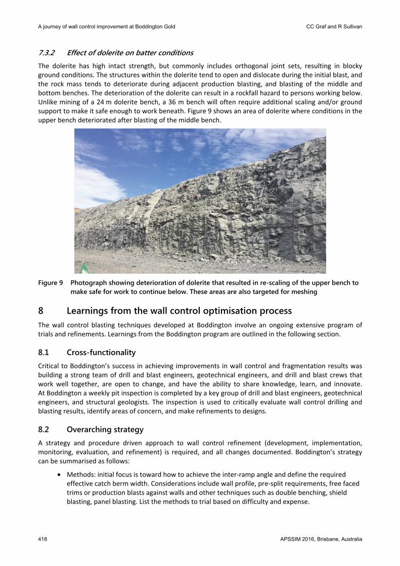
7.3.2 Effect of dolerite on batter conditions
The dolerite has high intact strength, but commonly includes orthogonal joint sets, resulting in blocky ground conditions. The structures within the dolerite tend to open and dislocate during the initial blast, and the rock mass tends to deteriorate during adjacent production blasting, and blasting of the middle and bottom benches. The deterioration of the dolerite can result in a rockfall hazard to persons working below. Unlike mining of a 24 m dolerite bench, a 36 m bench will often require additional scaling and/or ground support to make it safe enough to work beneath. Figure 9 shows an area of dolerite where conditions in the upper bench deteriorated after blasting of the middle bench.
Figure 9 Photograph showing deterioration of dolerite that resulted in re-scaling of the upper bench to
make safe for work to continue below. These areas are also targeted for meshing
8 Learnings from the wall control optimisation process The wall control blasting techniques developed at Boddington involve an ongoing extensive program of trials and refinements. Learnings from the Boddington program are outlined in the following section.
8.1 Cross-functionality Critical to Boddington’s success in achieving improvements in wall control and fragmentation results was building a strong team of drill and blast engineers, geotechnical engineers, and drill and blast crews that work well together, are open to change, and have the ability to share knowledge, learn, and innovate. At Boddington a weekly pit inspection is completed by a key group of drill and blast engineers, geotechnical engineers, and structural geologists. The inspection is used to critically evaluate wall control drilling and blasting results, identify areas of concern, and make refinements to designs.
8.2 Overarching strategy A strategy and procedure driven approach to wall control refinement (development, implementation, monitoring, evaluation, and refinement) is required, and all changes documented. Boddington’s strategy can be summarised as follows:
• Methods: initial focus is toward how to achieve the inter-ramp angle and define the required effective catch berm width. Considerations include wall profile, pre-split requirements, free faced trims or production blasts against walls and other techniques such as double benching, shield blasting, panel blasting. List the methods to trial based on difficulty and expense.

Monitoring slopes and rockfalls
APSSIM 2016, Brisbane, Australia 419
• Equipment: a reasonable range of options is required to be explored and trialed. Consider equipment selection for the method selected, drill hole size, length, explosive types and initiating systems. Work closely with explosives manufacturers to trial and refine different products to best suit the site rock mass conditions and method.
• Parameters: a good wall in difficult conditions is a carefully chosen set of burdens, spacings, charge weights, and timings all working well together. An assessment of drilling and blasting results will take time and patience. This is an iterative process.
• Results: results will indicate whether the combination of parameters is working or whether the method and/or equipment and/or parameters need to be re-evaluated.
Implicit in the strategy is the commitment to continuous improvement, and ongoing internal and external peer review of the operating considerations. This process may take a number of years to complete.
8.3 Embrace change At Boddington the original design of a vertical batter face configuration, firing of production blasts against the high wall with no free faced trims, and selection of only one explosive manufacturer were highly favoured options. Efforts to move away from this method, equipment, and parameters took time, involved careful stakeholder engagement and a commitment to innovate.
Design is an iterative process. As part of this process it is important not to over-complicate, be able to acknowledge when something is not working, have review and stop points, and understand when to go ‘back to basics’. Persistence, resilience, and an openness to change is required.
9 Future work
9.1 Wall steepening trial The reductions in crest loss and improved batter quality led to the ability to commence a wall-steepening trial to commence in late 2015. An incremental approach to wall-steepening has been adopted involving changing the angle of the upper bench. The targeted inter-ramp angle is 60.8 degrees.
A fundamental aspect of any steepening trial is whether the steeper configuration can reliably provide the required rockfall protection. The main risks involved in the slope steepening trial are the same as those that apply to the current configuration. These include local occurrences of adversely oriented structure, fracture zones relating to blasting and/or ground conditions, discrepancies between as-built and design bench geometry related to operational execution, and incomplete scaling.
9.2 Dolerite refinements Continued refinements to drill and blast methods and parameters are being completed in dolerite. Particular focus is the middle and lower benches, and subsequent deterioration of the upper bench. Proposed trials include modification of dolerite firing directions and blast boundaries, modification of hole diameters and powder factor in holes adjacent to the pit wall, and free faced trim blasts on the second, and potentially third, bench.
10 Conclusion Wall control blasting techniques developed at Boddington have involved a ‘back to basics’ approach and an ongoing extensive program of trials and refinements. Critical to Boddington’s success was building a strong team of drill and blast engineers, geotechnical engineers, and drill and blast crews whom collaborate, are open to change, and have the ability to learn, and innovate. This teamwork, routine inspections, data collection, and a well-defined strategy are required to provide a basis for decisions to be made.

A journey of wall control improvement at Boddington Gold CC Graf and R Sullivan
420 APSSIM 2016, Brisbane, Australia
Through the implementation and continued refinement of these techniques crest loss has been reduced by an average of 2 m, from 4.3 to 2.3 m. A consistent attainment of the pit wall design has been achieved in the andesite and diorite with minimum loss of effective catch berm and good quality batter conditions.
Reductions in crest loss and improved batter conditions have enabled wall-steepening trials to commence in late 2015. By maximising the pit slope angle, the stripping ratio can be reduced and in turn can have a significant impact to the economics of an open pit operation. A fundamental aspect of any steepening trial is whether the steeper configuration can reliably provide the required rockfall protection. An incremental approach to wall-steepening has been adopted, the initial trial is a 60.8 degree inter-ramp angle.
Acknowledgement The authors acknowledge the permission of Newmont Boddington Gold to publish this paper. The contribution of the teams at Boddington, in particular Zachary Thomas and Nathan Brockhurst, and support of the geotechnical group, John Lupo, Tom Byers, and Frans Basson, is greatly appreciated.
References Deere, DU, Hendron, AJ, Patton, FD & Cording, EJ 1967, ‘Design of surface and near surface construction in rock, in C Fairhurst (ed.),
Proceedings of the Eighth US Symposium of Rock Mechanics, New York, pp. 237–302. Lorig, L, Stacey, P & Read, J 2009, ‘Slope design methods’, in J Read & P Stacey (eds), Guidelines for Open Pit Slope Design,
CRC Press/Balkema, The Netherlands. O’Bryan, P 2013, ‘Wall failure and damage mechanisms’, in Blasting for Stable Slopes, Australian Centre for Geomechanics, Perth,
Western Australia. Ryan, TM & Pryor, PR 2000, ‘Designing Catch Benches and Interramp Slopes’, in WA Hustrulid, MK McCarter & DJ Van Zyl (eds),
Slope Stability in Surface Mining, Littleton, Colorado, pp. 27–38.