a hidden markov model-based assembly contact recognition system
TRANSCRIPT
Mechatronics 13 (2003) 1001–1023
A hidden Markov model-based assemblycontact recognition system
H.Y.K. Lau *
Department of Industrial and Manufacturing Systems Engineering, The University of Hong Kong,
Pokfulam Road, Hong Kong
Received 15 August 2002; accepted 23 August 2002
Abstract
A hidden Markov model (HMM)-based assembly contact state recognition system is de-
signed and implemented. The system utilizes the force/torque data captured from a wrist force
sensor to extract the intrinsic spatial relationships of contact formations arise from robotic
assembly. The paper introduces a theoretical framework for contact recognition based on
discrete HMM with special emphasis on the practical realization of the system using an in-
dustrial robot. With the detailed exposition of the major algorithms for solving the three key
problems in HMM, namely, the evaluation of observation sequence probability, optimization
of state sequence probability, and optimization of model parameters, a working prototype of
HMM-based system is developed. The performance of the contact recognition system is in-
vestigated by using experimental studies. The results obtained clearly demonstrate that HMM
is an effective means for assembly contact modelling and identification, and that the frame-
work reported in this paper provides an essential ground work for the development of a
practical intelligent robotic system.
� 2003 Elsevier Science Ltd. All rights reserved.
Keywords: Intelligent assembly; Hidden Markov model; Contact recognition; Industrial robotics
1. Introduction
Robotic assembly is a classical problem in industrial robotic where a rigid robot
with accurate actuators under a position-based controller executes sequences of pre-
determined operations in a structured workspace. In reality, jigs and fixtures ware,
and tolerance exists in work pieces, thus limiting the deployment of robots in most
* Fax: +852-2858-6535.
E-mail address: [email protected] (H.Y.K. Lau).
0957-4158/03/$ - see front matter � 2003 Elsevier Science Ltd. All rights reserved.
doi:10.1016/S0957-4158(03)00012-6
1002 H.Y.K. Lau / Mechatronics 13 (2003) 1001–1023
assembly tasks especially where tight tolerance contacts and mating of parts are
involved.
With a view to overcome this limitation, force-based control strategies have been
widely investigated. In the past decades, force-control strategies including the gen-eralized spring and damper [22], hybrid force/position control [10,16], impedance
control [8] and others more recent developments [24] have been suggested. These
strategies provide means to construct force feedback control systems where force
information acquired from joint torque and wrist force sensors is used to modify the
robot motion.
For most practical assembly systems, definitive models are often difficult to obtain
for a force controlled system to perform satisfactorily. In order to relax the con-
straints that required precise modeling of the environment and assembly systems;and uncertainties such as actuator frictions, artificial intelligence (AI) techniques
have been deployed in recent years. AI techniques such as neural networks, fuzzy
logic and genetic algorithms have been used to learn and optimize parameters that
are very difficult to model (see Section 3).
1.1. Fundamental issues of robotic assembly
However, the incorporation of AI techniques into control algorithms to �self-tune�control parameters for robotic assembly does not address the fundamental problem
of knowing what the robot is doing at a particular moment in time. In practice,
a typical assembly operation often consists of a sequence of multi-step motions [22].
Due to the discontinuous nature of an assembly process that is dictated by the ge-
ometry of the robot, the work piece and the fixtures, such a motion sequence
computation is often so complex for a single control strategy to efficiently accom-
plish. Furthermore, effective control strategies are highly nonlinear and dependenton the �states� of the assembly process. Direct feedback control strategies are limited
unless the control rules are modified in accordance with the change of assembly
states in an assembly operation [1,7]. Thus, the fundamental problem in robotic
assembly is the ability to recognize assembly states, and this very problem must be
addressed prior to the deployment of appropriate control strategies.
The primary objective of this paper is to develop a framework to recognize the
nature and classify the assembly contact states based on the force/torque information
resulted from contact formation between a work piece and its environment. Al-though it may seems more direct to obtain information of contact formations with
computer vision, under cost consideration, complexity of vision algorithms, and
most importantly, the practicality in assembly operations where the relative motion
is very small, it is more favourable to using force/torque measurement in contact
recognition.
1.2. Assembly state recognition
As the focus of the research is to address the problem of recognizing assembly
contact states, an HMM-based contact state recognizer (HMM-CSR) is designed
H.Y.K. Lau / Mechatronics 13 (2003) 1001–1023 1003
and developed using a modified industrial robot to demonstrate the feasibility and
operation of contact state recognition. The system can be viewed is a high-level
feedback control system that aims at perceiving the environment in terms of sym-bolic expressions, in this case, the force/torque patterns that are captured. In the
classification of contact states, the concept of fundamental contact (FC) is intro-
duced that provides a basis for describing generic contact formations that may
consist of zero, one or more contact pairs between the work piece and the interacting
environment. In simpler terms, the concept of FC can be regarded as a primitive
form of contact formation, where a FC only involves a single pair of contact fea-
tures. An HMM-modeled FC is interpreted and analyzed with the attachment of
symbolic meaning such as spatial relationship and geometrical information of con-tacting objects. It is seen that this approach to geometrical analysis can provide high-
level knowledge for robot motion planning systems to execute appropriate motion to
achieve fully intelligent and unsupervised robotic assembly.
The paper starts by introducing the concept and definition of assembly contact
states, which is followed by their HMM-based modeling. The design of the contact
state recognizer is discussed and an implementation of such system is described. The
paper concludes with the presentation of the results from experimental studies with
the implemented system for the classification and identification of representativecontact formations that are found in robotic assembly.
2. Assembly contact states
2.1. The notion of assembly contacts
Contacts are common scenarios in the robotic assembly. A contact is discrete in
nature and can be defined and interpreted as a physical contact formation that is
resulted from the geometric arrangement of the work piece and its interacting en-
vironment, which may consists of zero, one or more contact pairs [12]. The philo-
sophy of contact-based control strategy for robotic assembly is based on the fact each
contact formation between a work piece that is held by a robot end-effector and itsenvironment produces a pattern of force/torque. Such force/torque information can
be captured accurately and clustered to represent a corresponding contact state that
characterizes a unique spatial configuration of the interaction made between the
work piece and the environment. Furthermore, as long as contact occurs, the degree
of freedom posed to the manipulated object is reduced by at least one. Thus, it is
resourceful to use the interpreted or resolved geometric information to guide the
process of assembly. Therefore, the successful representation of contact space and
the analysis of contact state is a directed approach to achieve successful roboticassembly.
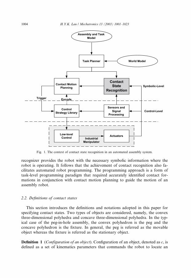
In an automated assembly framework as shown in Fig. 1, recognition of contact
states is essential in planning and executing contact-based assembly motions [23].
The objective of providing an intelligent assembly robot with a contact recognizer
is to equip it with the capability of perception of the environment. The contact
Symbolic-Level
Control-Level
Low-levelControl Actuators
Sensors andSignal
Processing
ControlStrategy Library
Contact MotionPlanning
ContactState
Recognition
Task Planner
Assembly and TaskModel
Encode
World Model
Trigger
IndustrialManipulator
Fig. 1. The context of contact state recognition in an automated assembly system.
1004 H.Y.K. Lau / Mechatronics 13 (2003) 1001–1023
recognizer provides the robot with the necessary symbolic information where the
robot is operating. It follows that the achievement of contact recognition also fa-
cilitates automated robot programming. The programming approach is a form of
task-level programming paradigm that required accurately identified contact for-mations in conjunction with contact motion planning to guide the motion of an
assembly robot.
2.2. Definitions of contact states
This section introduces the definitions and notations adopted in this paper for
specifying contact states. Two types of objects are considered, namely, the convex
three-dimensional polyhedra and concave three-dimensional polyhedra. In the typ-
ical case of the peg-in-hole assembly, the convex polyhedron is the peg and the
concave polyhedron is the fixture. In general, the peg is referred as the movableobject whereas the fixture is referred as the stationary object.
Definition 1 (Configuration of an object). Configuration of an object, denoted as c, isdefined as a set of kinematics parameters that commands the robot to locate an
H.Y.K. Lau / Mechatronics 13 (2003) 1001–1023 1005
object for a given set of joint angles, fhig. The corresponding representation in
Cartesian space is given by c ¼ ðx; y; z; yaw; pitch; rollÞT . As a result, configuration
can be regarded as the lowest level of the assembly, which is formed in accordancewith the specific kinematics constraints. Therefore, c can be expressed as
fhig; or
ðx; y; z; yaw; pitch; rollÞT�
Definition 2 (Configuration space). Configuration space, denoted by C, is defined as
an Rn space that collects all the configuration of an object, C.
Definition 3 (Contact feature). A contact feature is defined as a surface element of a
polyhedron. A contact feature contacting with the environment or another poly-
hedron is denoted by F,ff ; e; vg where f is the face of the object, e is the edge of theobject and v is the vertex of the object.
Definition 4 (Fundamental contact). A FC is specified by an ordered pair of contact
feature, F . Accordingly, a FC is described and formulated as a contact pair } ¼ðF i
A; FjBÞ 2 FAFB where F i
A and F jB are the contacting features i and j selected from
object A and object B, respectively.
Definition 5 (Contact state). A contact state (CS) between two polyhedra is a set ofFCs. The contact state may consists of several FCs depending on the geometry of the
two polyhedra. A multiple contact state, CSn is denoted by
CSn ¼ f. . . ; ðF iA; F
jBÞ; . . .g 2 }� }� � � � � }|fflfflfflfflfflfflfflfflfflfflfflffl{zfflfflfflfflfflfflfflfflfflfflfflffl}
n
where n is the number of contact pairs.
3. Contact recognition with symbolic feedback
3.1. Contact recognition in robotic assembly
In general terms, contact recognition in robotic assembly is defined as a process of
using contact sensing technique to obtain geometrical information of contact with
corresponding symbolic interpretations during an assembly process. As abovemen-
tioned, the primary objective introducing a contact state recognizer to an assembly
robot is to give it the capability of perception of the environment such that appro-
priate control actions can be exerted to successfully an assembly task.Results from forgoing studies suggested that the benefits of deploying a contact-
based assembly system are numerous. Firstly, symbolic interpretations of assembly
states provide invaluable high-level knowledge of assembly operations to robot
programmers. Secondly, the approach reduces the precision requirement of sensors
as captured signals are mapped to symbolic information, rather than directly using
1006 H.Y.K. Lau / Mechatronics 13 (2003) 1001–1023
the acquired sensory information. The uncertain and error-prone sensory data are
empirically validated through the incorporation of a template training process, by
which a smaller number of training data is used to train the recognition system.
Performing contact recognition by means of active sensing has widely beenstudied. Numerous researches such as analytical analysis by polyhedral convex
theory [7], static modelling by Petri net [11], rule-based contact analysis [18], fuzzy
logic- and neural network-based approaches [13,19] have been adopted in designing
high-performance recognition systems with different degrees of success. However,
due to intensive computation, extensive training regimes, and difficulties in con-
structing analytical models, some limitations are encountered.
An alternative approach of using HMM to model contact formations in assembly
operations is considered in this paper. Researches in pattern recognition [6], speechrecognition [14], character recognition [17] and data verification, DNA and protein
modeling [2] has established the power of HMM in modeling physical phenomena.
In particular, HMM was used as a speech recognizer to model and recognize input
voice arising from human speech [15]. With the view that assembly states within a
typical assembly sequence are inter-related and that the occurrence of contact for-
mation between a work piece and the mating parts are normally distributed, this
paper adopts the hidden Markov model (HMM) [9] to model contact formations
that characterized assembly states in robotic assembly. As such, the adaptation of aHMM-based contact recognition system in the reported research provides cognitive
knowledge for assembly operations by way of symbolic interpretations and geo-
metrical relationships.
3.2. Hidden Markov modeling
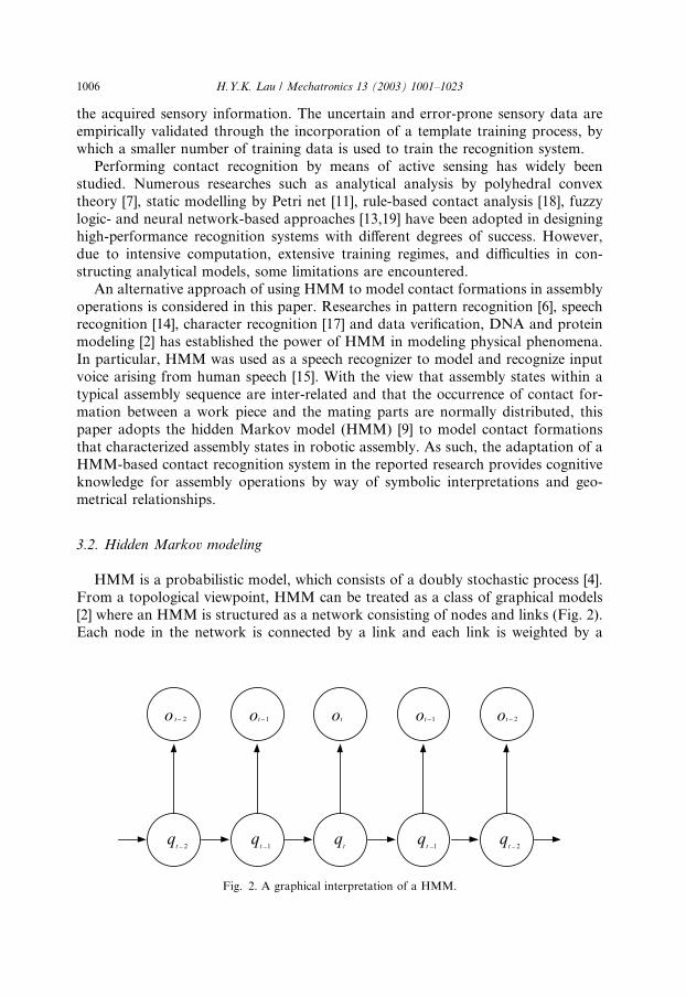
HMM is a probabilistic model, which consists of a doubly stochastic process [4].
From a topological viewpoint, HMM can be treated as a class of graphical models
[2] where an HMM is structured as a network consisting of nodes and links (Fig. 2).Each node in the network is connected by a link and each link is weighted by a
qt 2
qt
qt 1
qt 1
qt 2
ot 2 ot 2ot 1otot 1− − − −
−−−−
Fig. 2. A graphical interpretation of a HMM.
H.Y.K. Lau / Mechatronics 13 (2003) 1001–1023 1007
probabilistic value. A HMM consists of two stochastic processes, with an under-
lying process being a Markov chain and an observable process being another sto-
chastic process characterized by a probabilistic distribution, either discrete orcontinuous.
As depicted by Fig. 2, qi and oi are the underlying states and observable symbols
in an HMM, respectively. As the basic infrastructure of an HMM is a Markov chain,
a state of the underlying process is also a Markov chain that has a strong Markov
property. In general, an HMM is defined as a triplet k ¼ ðA;B; pÞ, where A is a
transition matrix consists of transition probabilities aij ¼ Prðqtþ1 ¼ sjjqt ¼ siÞ, Bcontains the probabilities of the observable symbols bij ¼ Prðot ¼ vkjqt ¼ siÞ, and p is
the initial state distribution. Other important parameters of an HMM include thenumber of Markov states, N , the number of observable symbols,M , and the states of
the model si 2 S.From the nature of an HMM, it can be used as a generative model to generate an
observation sequence O ¼ foig where 16 i6 T and T is the number of observations
in the sequence given appropriate values of N , M , A, B and p. In the context of
assembly state modeling, given a sequence of force/torque data as the observable
symbols, the underlying assembly state can be evaluated accordingly provided that
suitable HMM parameters are defined. Specifically, in adopting the hidden Markovmodeling technique to real-world applications such as assembly state modeling, the
problems of (1) evaluating the probability of observation sequence O ¼ o1; o2; . . . ; oTfor a given model k, (2) evaluating the most probable state sequence Q ¼ q1; q2; . . . ;qT given the observation sequence, O ¼ o1; o2; . . . ; oT , and the model k, and (3)
adjusting the model parameters N , M , A, B and p in order to maximize the prob-
ability PrðQjO; kÞ such that the performance of the HMM in contact recognition is
optimized must be considered.
The solutions to the three problems that are deployed in the implementation ofthe contact state recognition system in this research is given in Appendix A.
4. An HMM-based contact recognition system
4.1. System design
The design of the HMM-based contact state recognition system is built upon a set
of HMMs that are suitably trained with force/torque information of assembly
contact states. Each well-trained HMM represents a corresponding contact type,
that constitutes the knowledge of geometrical information of assembly operations, in
terms of a set of FC states. The contact state recognition system consists of a signalpreprocessing module, a symbol mapping process, and the set of HMMs repre-
senting the FCs. The architecture of the contact state recognition system is given by
Fig. 3.
The following procedures are undertaken to develop a suitable system for robotic
assembly state recognition.
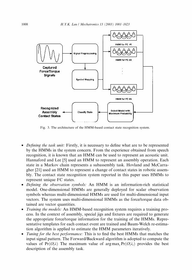
Fig. 3. The architecture of the HMM-based contact state recognition system.
1008 H.Y.K. Lau / Mechatronics 13 (2003) 1001–1023
• Defining the task unit: Firstly, it is necessary to define what are to be represented
by the HMMs in the system concern. From the experience obtained from speech
recognition, it is known that an HMM can be used to represent an acoustic unit.
Hannaford and Lee [5] used an HMM to represent an assembly operation. Each
state in a Markov chain represents a subassembly task. Hovland and McCarra-
gher [21] used an HMM to represent a change of contact states in robotic assem-
bly. The contact state recognition system reported in this paper uses HMMs to
represent unique FC states.• Defining the observation symbols: An HMM is an information-rich statistical
model. One-dimensional HMMs are generally deployed for scalar observation
symbols whereas multi-dimensional HMMs are used for multi-dimensional input
vectors. The system uses multi-dimensional HMMs as the force/torque data ob-
tained are vector quantities.
• Training the models: An HMM-based recognition system requires a training pro-
cess. In the context of assembly, special jigs and fixtures are required to generate
the appropriate force/torque information for the training of the HMMs. Repre-sentative templates for each contact event are trained and Baum-Welch re-estima-
tion algorithm is applied to estimate the HMM parameters iteratively.
• Tuning for the best performance: This is to find the best HMMs that matches the
input signal pattern. The Forward/Backward algorithm is adopted to compute the
values of PrðOjkÞ The maximum value of argmaxi PrðOjkiÞ provides the best
description of the assembly task.
H.Y.K. Lau / Mechatronics 13 (2003) 1001–1023 1009
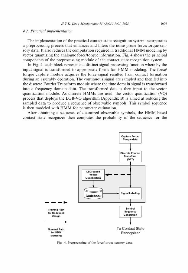
4.2. Practical implementation
The implementation of the practical contact state recognition system incorporatesa preprocessing process that enhances and filters the noise prone force/torque sen-
sory data. It also reduces the computation required in traditional HMMmodeling by
vector quantizing the analogue force/torque information. Fig. 4 shows the principal
components of the preprocessing module of the contact state recognition system.
In Fig. 4, each block represents a distinct signal processing function where by the
input signal is transformed to appropriate forms for HMM modeling. The force/
torque capture module acquires the force signal resulted from contact formation
during an assembly operation. The continuous signal are sampled and then fed intothe discrete Fourier Transform module where the time domain signal is transformed
into a frequency domain data. The transformed data is then input to the vector
quantization module. As discrete HMMs are used, the vector quantization (VQ)
process that deploys the LGB-VQ algorithm (Appendix B) is aimed at reducing the
sampled data to produce a sequence of observable symbols. This symbol sequence
is then modeled with HMM for parameter estimation.
After obtaining a sequence of quantized observable symbols, the HMM-based
contact state recognizer then computes the probability of the sequence for the
Capture Force/Torque data
Discrete FourierTransform
(DFT)
LBG-basedVector
Quantization
Signal Labeling
SymbolSequenceGeneration
Training Pathfor Codebook
Design
Nominal Pathfor HMMModeling
Codebook
To Contact StateRecognizer
Fig. 4. Preprocessing of the force/torque sensory data.

Parameter Optimization
SensoryInformation
Pattern
SignalPreprocessor
Define TaskUnit
DefineDistribution ofObservation
Train Models
Evaluation
Training?
A Collection ofHMMs
Yes
No
Contact State
End
Training?
Yes (Training completed)
No (Recognition)
Selection of Discrete andContinuous
Selection of Markov StateRepresention
Evaluation?
Yes
No
DefineDistribution ofObservation
Train Models
Subtask-basedHMM
Estimation ofState Sequence
The EndRecgonzied
Hidden StatesSequenceRecovered
Fig. 5. The operation of the HMM-based contact recognition system.
1010 H.Y.K. Lau / Mechatronics 13 (2003) 1001–1023
H.Y.K. Lau / Mechatronics 13 (2003) 1001–1023 1011
well-trained HMMs. That is, the computation of PrðOjkiÞ, where O is an observ-
able sequence, ki is the ith HMM. Then the contact state is mapped (Appendix B)
by selecting the corresponding index i according to the condition argmaxi PrðOjkiÞ.The recognized assembly contact state is then obtained and can be used by the
robot controller to derive appropriate control actions to complete the assembly
task. The operation of the entire contact state recognition system is summarized in
Fig. 5.
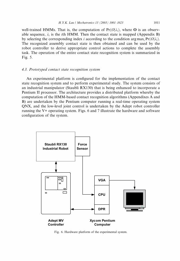
4.3. Prototyped contact state recognition system
An experimental platform is configured for the implementation of the contact
state recognition system and to perform experimental study. The system consists of
an industrial manipulator (Staubli RX130) that is being enhanced to incorporate a
Pentium II processor. The architecture provides a distributed platform whereby the
computation of the HMM-based contact recognition algorithms (Appendixes A and
B) are undertaken by the Pentium computer running a real-time operating system
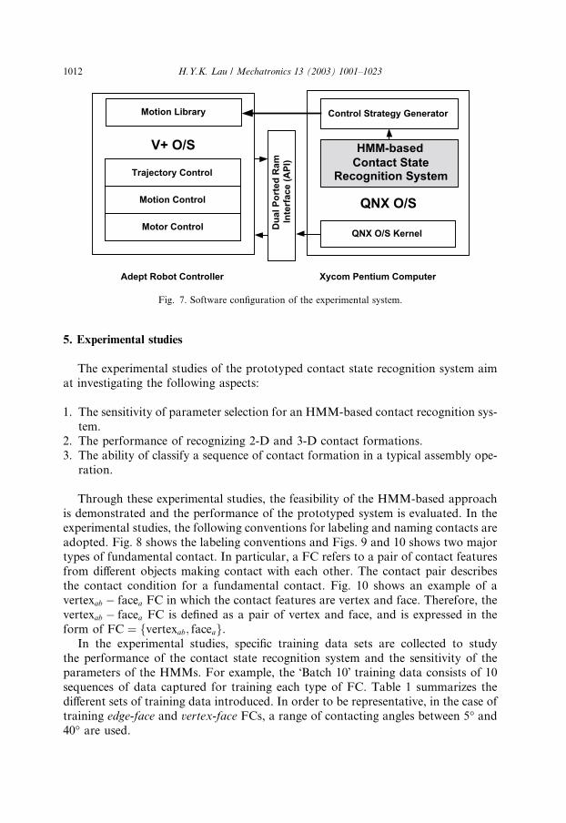
QNX, and the low-level joint control is undertaken by the Adept robot controllerrunning the V+ operating system. Figs. 6 and 7 illustrate the hardware and software
configuration of the system.
Xycom PentiumComputer
VGA
DPR
CPU
ForceSensor
Adept MVController
Staubli RX130Industrial Robot
Fig. 6. Hardware platform of the experimental system.
Motor Control
Motion Control
Trajectory Control
Dua
l Por
ted
Ram
Inte
rfac
e (A
PI)
QNX O/S Kernel
Adept Robot Controller Xycom Pentium Computer
V+ O/S
Motion Library Control Strategy Generator
HMM-basedContact State
Recognition System
QNX O/S
Fig. 7. Software configuration of the experimental system.
1012 H.Y.K. Lau / Mechatronics 13 (2003) 1001–1023
5. Experimental studies
The experimental studies of the prototyped contact state recognition system aim
at investigating the following aspects:
1. The sensitivity of parameter selection for an HMM-based contact recognition sys-
tem.2. The performance of recognizing 2-D and 3-D contact formations.
3. The ability of classify a sequence of contact formation in a typical assembly ope-
ration.
Through these experimental studies, the feasibility of the HMM-based approach
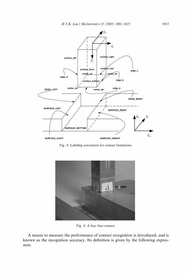
is demonstrated and the performance of the prototyped system is evaluated. In the
experimental studies, the following conventions for labeling and naming contacts are
adopted. Fig. 8 shows the labeling conventions and Figs. 9 and 10 shows two majortypes of fundamental contact. In particular, a FC refers to a pair of contact features
from different objects making contact with each other. The contact pair describes
the contact condition for a fundamental contact. Fig. 10 shows an example of a
vertexab � facea FC in which the contact features are vertex and face. Therefore, the
vertexab � facea FC is defined as a pair of vertex and face, and is expressed in the
form of FC ¼ fvertexab; faceag.In the experimental studies, specific training data sets are collected to study
the performance of the contact state recognition system and the sensitivity of theparameters of the HMMs. For example, the �Batch 10� training data consists of 10
sequences of data captured for training each type of FC. Table 1 summarizes the
different sets of training data introduced. In order to be representative, in the case of
training edge-face and vertex-face FCs, a range of contacting angles between 5� and40� are used.
surface_front
surface_rightsurface_left
surface_rear
surface_bottom
edge_a
edge_b
edge_c
edge_d
SURFACE_LEFTSURFACE_RIGHT
SURFACE_BOTTOM
SURFACE_VLEFT SURFACE_VRIGHT
EDGE_LEFT
EDGE_RIGHT
TX
TY
TZ
WX
WYWZ
vertex_ab
vertex_bcvertex_cd
vertex_da
Fig. 8. Labeling convention for contact formations.
Fig. 9. A face–face contact.
H.Y.K. Lau / Mechatronics 13 (2003) 1001–1023 1013
A means to measure the performance of contact recognition is introduced, and is
known as the recognition accuracy. Its definition is given by the following expres-
sion:
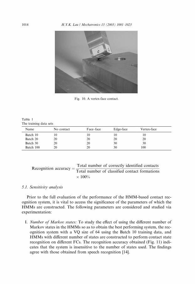
Fig. 10. A vertex-face contact.
Table 1
The training data sets
Name No contact Face–face Edge-face Vertex-face
Batch 10 10 10 10 10
Batch 20 20 20 20 20
Batch 30 20 20 30 30
Batch 100 20 20 30 100
1014 H.Y.K. Lau / Mechatronics 13 (2003) 1001–1023
Recognition accuracy ¼ Total number of correctly identified contacts
Total number of classified contact formations
� 100%
5.1. Sensitivity analysis
Prior to the full evaluation of the performance of the HMM-based contact rec-
ognition system, it is vital to access the significance of the parameters of which the
HMMs are constructed. The following parameters are considered and studied via
experimentation:
I. Number of Markov states: To study the effect of using the different number of
Markov states in the HMMs so as to obtain the best performing system, the rec-ognition system with a VQ size of 64 using the Batch 10 training data, and
HMMs with different number of states are constructed to perform contact state
recognition on different FCs. The recognition accuracy obtained (Fig. 11) indi-
cates that the system is insensitive to the number of states used. The findings
agree with those obtained from speech recognition [14].

Fig. 12. Recognition accuracy versus VQ sizes.
Fig. 11. Recognition accuracy versus number of HMM states.
H.Y.K. Lau / Mechatronics 13 (2003) 1001–1023 1015
II. Quantization size: As VQ is one of the essential processes deployed in the rec-
ognition system based on discrete HMM, different quantization sizes for differ-
ent HMMs are studied using the Batch 10 training data to identify edge-type
FCs. The results (Fig. 12) shows that the recognition accuracy for different
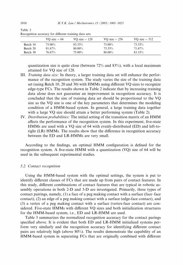
Table 2
Recognition accuracy for different training data sets
VQ size ¼ 64 VQ size ¼ 128 VQ size ¼ 256 VQ size ¼ 512
Batch 10 75.00% 83.33% 75.00% 73.33%
Batch 20 81.67% 80.00% 73.33% 71.67%
Batch 30 76.67% 75.00% 80.00% 83.33%
1016 H.Y.K. Lau / Mechatronics 13 (2003) 1001–1023
quantization size is quite close (between 72% and 83%), with a local maximum
attained for VQ size of 128.
III. Training data size: In theory, a larger training data set will enhance the perfor-
mance of the recognition system. The study varies the size of the training data
set (using Batch 10, 20 and 30) with HMMs using different VQ sizes to recognize
edge-type FCs. The results shown in Table 2 indicate that by increasing training
data alone does not guarantee an improvement in recognition accuracy. It is
concluded that the size of training data set should be proportional to the VQsize as the VQ size is one of the key parameters that determines the modeling
condition of a HMM-based system. In general, a large training data together
with a large VQ size should attain a better performing system (Table 2).
IV. Distribution probabilities: The initial setting of the transition matrix of an HMM
affects the performance of the recognition system. In this experiment, five-state
HMMs are used with a VQ size of 64 with evenly-distributed (ED) and left-to-
right (LR) HMMs. The results show that the difference in recognition accuracy
between the ED and LR-HMMs are very small.
According to the findings, an optimal HMM configuration is defined for the
recognition system. A five-state HMM with a quantization (VQ) size of 64 will be
used in the subsequent experimental studies.
5.2. Contact recognition
Using the HMM-based system with the optimal settings, the system is put to
identify different classes of FCs that are made up from pairs of contact features. Inthis study, different combinations of contact features that are typical in robotic as-
sembly operations in both 2-D and 3-D are investigated. Primarily, three types of
contact pairings, namely, (1) a face of a peg making contact with a surface (face–face
contact), (2) an edge of a peg making contact with a surface (edge-face contact), and
(3) a vertex of a peg making contact with a surface (vertex-face contact) are con-
sidered. Five-state HMMs with different VQ sizes and both initialization structures
for the HMM-based system, i.e., ED and LR-HMM are used.
Table 3 summarizes the normalized recognition accuracy for the contact paringsspecified above. It is evident that both ED and LR-HMM initialized systems per-
form very similarly and the recognition accuracy for identifying different contact
pairs are relatively high (above 80%). The results demonstrate the capability of an
HMM-based system in separating FCs that are originally combined with different
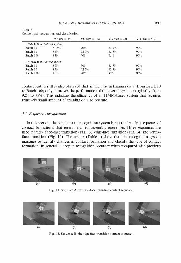
Table 3
Contact pair recognition and classification
VQ size ¼ 64 VQ size ¼ 128 VQ size ¼ 256 VQ size ¼ 512
ED-HMM initialized system
Batch 10 92.5% 90% 82.5% 90%
Batch 30 95% 92.5% 82.5% 90%
Batch 100 95% 90% 85% 90%
LR-HMM initialized system
Batch 10 95% 90% 82.5% 90%
Batch 30 95% 92.5% 82.5% 90%
Batch 100 95% 90% 85% 90%
H.Y.K. Lau / Mechatronics 13 (2003) 1001–1023 1017
contact features. It is also observed that an increase in training data (from Batch 10
to Batch 100) only improves the performance of the overall system marginally (from
92% to 95%). This indicates the efficiency of an HMM-based system that requires
relatively small amount of training data to operate.
5.3. Sequence classification
In this section, the contact state recognition system is put to identify a sequence of
contact formations that resemble a real assembly operation. Three sequences are
used, namely, face–face transition (Fig. 13), edge-face transition (Fig. 14) and vertex-face transition (Fig. 15). The results (Table 4) show that the recognition system
manages to identify changes in contact formation and classify the type of contact
formation. In general, a drop in recognition accuracy when compared with previous
Fig. 13. Sequence A: the face–face transition contact sequence.
Fig. 14. Sequence B: the edge-face transition contact sequence.

Fig. 15. Sequence C: the vertex-face transition contact sequence.
Table 4
Contact state recognition for motion sequences A, B and C
No contact Face–face Edge-face Vertex-face
Sequence A 80% 100%
Sequence B 100% 50%
Sequence C 100% 40%
1018 H.Y.K. Lau / Mechatronics 13 (2003) 1001–1023
studies may be due to the decrease in the quality of force/torque signals captured
when the robot is in motion and the occurrence of sliding motions between the peg
and the surface in contact. However, when compared with results obtained fromspeech recognition where the recognition accuracy for discrete HMM is in the region
of 35%, the results obtained for assembly state recognition is comparable and con-
sistent. Despite the simple nature of the sequences used in this experimental study,
the results demonstrate the ability of the HMM-based system in extracting contact
state information in a dynamic situation.
6. Conclusions
This paper focuses on the developments of an assembly contact state recognition
system based on the stochastic framework of HMM. A force-based approach has
been adopted to infer assembly contact states, which is in contrast to more tradi-tional kinematics-based or CAD-based approaches. It has been shown by experi-
ments that such an approach allows for dynamic force and moment measurements,
and there are no restrictions to system accelerations, which is in contrast to the
limitations of quasi-static motions.
In this paper, discrete hidden Markov modeling techniques have been deployed
where FCs are represented by mapping force and torque signals. Each FC has been
modeled by a discrete HMM that consists of a set of parameters that characterize the
physical properties and contact conditions of interacting objects. Based on thetheoretical framework of HMM, the design and implementation of a practical
HMM-based contact state recognition system has been presented. In addition, an
experimental system that consists of a modified industrial robot has been developed
to study the performance of the proposed contact recognition system. The results
H.Y.K. Lau / Mechatronics 13 (2003) 1001–1023 1019
have clearly indicated the superiority of the HMM-based system in recognizing
typical contact formations, and in identifying the potential of deploying the state
information for the future construction of an intelligent assembly robotic system.
Acknowledgement
The research is partially funded by the Hong Kong Research Grant Council
under the Grant HKU 7075/98E.
Appendix A
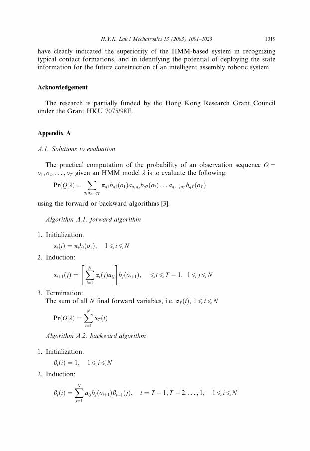
A.1. Solutions to evaluation
The practical computation of the probability of an observation sequence O ¼o1; o2; . . . ; oT given an HMM model k is to evaluate the following:
PrðQjkÞ ¼X
q1q2...qT
pq1bq1ðo1Þaq1q2bq2ðo2Þ . . . aqT�1qT bqT ðoT Þ
using the forward or backward algorithms [3].
Algorithm A.1: forward algorithm
1. Initialization:
atðiÞ ¼ pibiðo1Þ; 16 i6N
2. Induction:
atþ1ðjÞ ¼XNi¼1
atðjÞaij
" #bjðotþ1Þ; 6 t6 T � 1; 16 j6N
3. Termination:
The sum of all N final forward variables, i.e. aT ðiÞ, 16 i6N
PrðOjkÞ ¼XNi¼1
aT ðiÞ
Algorithm A.2: backward algorithm
1. Initialization:
btðiÞ ¼ 1; 16 i6N
2. Induction:
btðiÞ ¼XNj¼1
aijbjðotþ1Þbtþ1ðjÞ; t ¼ T � 1; T � 2; . . . ; 1; 16 i6N
1020
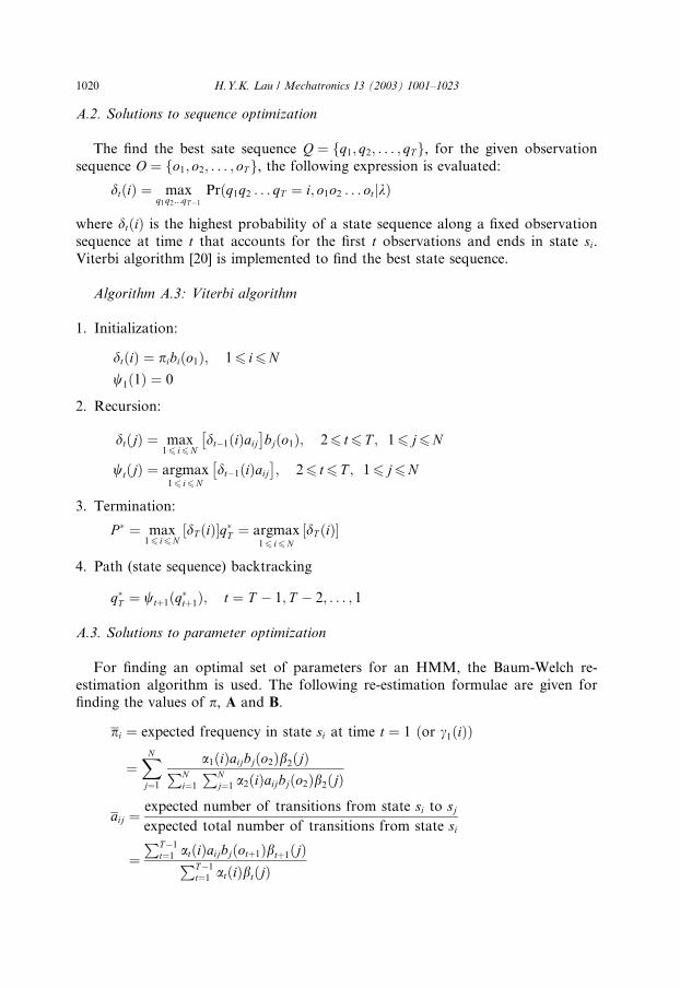
H.Y.K. Lau / Mechatronics 13 (2003) 1001–1023A.2. Solutions to sequence optimization
The find the best sate sequence Q ¼ fq1; q2; . . . ; qTg, for the given observation
sequence O ¼ fo1; o2; . . . ; oTg, the following expression is evaluated:
dtðiÞ ¼ maxq1q2...qT�1
Prðq1q2 . . . qT ¼ i; o1o2 . . . otjkÞ
where dtðiÞ is the highest probability of a state sequence along a fixed observation
sequence at time t that accounts for the first t observations and ends in state si.Viterbi algorithm [20] is implemented to find the best state sequence.
Algorithm A.3: Viterbi algorithm
1. Initialization:
dtðiÞ ¼ pibiðo1Þ; 16 i6N
w1ð1Þ ¼ 0
2. Recursion:
dtðjÞ ¼ max16 i6N
dt�1ðiÞaij �
bjðo1Þ; 26 t6 T ; 16 j6N
wtðjÞ ¼ argmax16 i6N
dt�1ðiÞaij �
; 26 t6 T ; 16 j6N
3. Termination:
P � ¼ max16 i6N
dT ðiÞ½ �q�T ¼ argmax16 i6N
dT ðiÞ½ �
4. Path (state sequence) backtracking
q�T ¼ wtþ1ðq�tþ1Þ; t ¼ T � 1; T � 2; . . . ; 1
A.3. Solutions to parameter optimization
For finding an optimal set of parameters for an HMM, the Baum-Welch re-
estimation algorithm is used. The following re-estimation formulae are given forfinding the values of p, A and B.
pi ¼ expected frequency in state si at time t ¼ 1 ðor c1ðiÞÞ
¼XNj¼1
a1ðiÞaijbjðo2Þb2ðjÞPNi¼1
PNj¼1 a2ðiÞaijbjðo2Þb2ðjÞ
aij ¼expected number of transitions from state si to sjexpected total number of transitions from state si
¼PT�1
t¼1 atðiÞaijbjðotþ1Þbtþ1ðjÞPT�1
t¼1 atðiÞbtðjÞ

wh
bo
H.Y.K. Lau / Mechatronics 13 (2003) 1001–1023 1021
bjðkÞ ¼expected number of times in state j and observing symbol vk
expected number of times in state j
¼PT�1
t¼1 atðiÞbtðjÞdðot; vkÞPT�1
t¼1 atðiÞbtðjÞwhere dðot; vkÞ ¼
1 if ot ¼ vk0 otherwise
�
According to the following stochastic constraints: XNi¼1
pi ¼ 1 andXNi¼1
pi ¼ 1 andXNi¼1
pi ¼ 1 for 16 i6N
Appendix B
Algorithm B.1: ALBG-VQ algorithm [25]
1. Initialization:
Assume all N k-dimensional training vectors to be one cluster C0, with a codebook
size of M ¼ 1 and codeword o0 ¼ 0. Evaluate its k-dimensional cluster centroidc0ð1Þ where iteration 1 is first to be initialized:
c0ð1Þ ¼ 1
N
XNn¼1
x0n
where x ¼ fxng is one sample of all N k-dimensional feature vectors at cluster C0.
2. Splitting:
To double the size of the codebook,M , by splitting each cluster into two. Thus, thecurrent codebook size M is split into 2M . Set M ¼ 2M by
ciþð1Þ ¼ cið1Þ þ eci�ð1Þ ¼ cið1Þ � e
�where 06 i6M � 1
i i
ere c is the centroid of the ith cluster of C , M is the size of the current code-ok, e is a k-dimensional splitting parameter vector.
3. Classification:
At the lth iteration, according to the nearest neighborhood rule, each k-dimensional sample x of training feature vectors is classified into one of he cluster
Ci.
x 2 CiðlÞifkx� ciðlÞk < kx� cjðlÞk where i 6¼ j; i; j ¼ 0; 1; . . . ;M � 1
4. Codebook updating:
The codeword (symbol) oi of each cluster Ci is updated by computing new cluster
centers ciðlþ 1Þ where j ¼ 0; 1; . . . ;M � 1 at the ðlþ 1Þth iteration.
ciðlþ 1Þ ¼ 1
N
XNn¼1
xin where xi 2 Ciðlþ 1Þ

1022 H.Y.K. Lau / Mechatronics 13 (2003) 1001–1023
and N is the number of feature vectors in cluster ciðlþ 1Þ at the ðlþ 1Þth itera-
tion, and, where 06 oi 6M � 1 and qð�Þ is the quantization operator.
5. Termination 1:
If the difference between the current overall distortion Dðlþ 1Þ and that of theprevious iteration DðlÞ is below a selected threshold, proceed to step 6, otherwise
returns to step 3, i.e.:
if jDðlþ 1Þ � DðlÞj < threshold; then goto Step 6
if jDðlþ 1Þ � DðlÞjP threshold; then goto Step 3
�6. Termination 2:
Is the codebook size M , is equal to the required VQ codebook size?
if yes; then STOP
if no; then goto Step 2
�
Algorithm B.2: symbol mapping algorithm
1. Choose the input signal x and calculate the centroid of the codeword accordingly:
kx� cik ¼Xk
h¼1
ðxh � cihÞ2
for i ¼ 0; 1; . . . ;M
2. Compute input signal x against each centroid.
3. Select the minimum values of the distance function.
4. Set codeword representing the signal x according to Step 3.
5. Obtain qðxÞ ¼ oi for 06 oi 6M � 1.
References
[1] Asada H, Yang. Skill acquisition from human experts through pattern processing of teaching data. In:
Proceedings of the 1989 IEEE International Conference on Robotics and Automation, 1989, p. 1302–
7.
[2] Baldi P, Brunak S. Bioinformatics: the machine learning approach. The MIT Press; 1998.
[3] Baun LE, Petrie T. Statistical inference for probabilistic functions of finite state Markov chains. Ann
Math Statist 1966;37(6):1554–63.
[4] Elliott RJ, Aggoum L, Moore JB. Hidden Markov models: estimation and control. Springer; 1995.
[5] Hannaford B, Lee P. Hidden Markov model analysis of force/torque information in telemanipulation.
Int J Robotics Res 1991;10(5):528–39.
[6] Hatzipantelis E, Penman J. The use of hidden Markov models for condition monitoring electrical
machines. In: IEEE Sixth International Conference on Electrical machines and Drives, 1993, p. 91–6.
[7] Hirai S. Analysis and planning of manipulation using the theory of polyhedral convex cones, Ph.D.
Thesis, Tokyo University, 1991.
[8] Hogan N. Mechanical impedance control in assistive devices and manipulators. In: Michael B et al.,
editors. Robot Motion: Planning and Control. The MIT Press; 1982.
[9] MacDonald IL, Zucchini W. Hidden Markov and other models for discrete-valued time series.
Chapman & Hall; 1997.
H.Y.K. Lau / Mechatronics 13 (2003) 1001–1023 1023
[10] Mason MT. Compliance and force control for computer controlled manipulators. IEEE Trans Syst,
Man, Cyber 1981;11(6):418–32.
[11] McCarragher BJ, Asada H. In-process monitoring for robotic assembly using dynamic process
models. ASME J Dyn Syst Meas Control 1993;115(2):261–75.
[12] McCarragher BJ, Asada H. The discrete event control of robotic assembly tasks. Trans ASME, Int J
Dyn Syst Meas Control 1995;117(Sept):384–93.
[13] Mitchell TM. Machine learning. New York: McGraw-Hill; 1997.
[14] Rabiner LR, Juang BH. Fundamentals of speech recognition. Prentice Hall; 1993.
[15] Rabiner LR. A tutorial on hidden Markov models and selected applications in speech recognition.
Proc IEEE 1989;77(2):257–86.
[16] Raibert MH, Craig JJ. Hybrid position/force control of manipulators. Trans ASME, J Dyn Syst Meas
Control 1981;102(June):126–33.
[17] Rayan MS, Nudd GR. Dynamic character recognition using hidden Markov models. Research
Report no. 244, Department of Computer Science, University of Warwick, 1993.
[18] Sikka P, McCarragher BJ. Monitoring contact using clustering and discriminant functions. In:
Proceedings of the 1996 IEE Int. Conf. on Robotics and Automation, April 1996, p. 1351–56.
[19] Skubic MA, Volz RA. Identifying single-ended contact formations from force sensor patterns. IEEE
Trans Rob Autom 2000;16(5):597–603.
[20] Viterbi AJ. Error bounds for convolutional codes and an asymptotically optimal decoding algorithm.
IEEE Trans Inf Theory 1967;13(April):260–9.
[21] Hovland GE, McCarragher BJ. Hidden Markov models as a process monitor in robotic assembly.
Inter J Robotics Research 1998;17(2):155–68.
[22] Whitney DE. Quasi-static assembly of compliantly supported parts. In: Michael B et al., editors.
Robot Motion: Planning and Control. The MIT Press; 1982.
[23] Xiao J, Liu L. Contact states:representation and recognizability in the presence of uncertainties. In:
Proceedings of the 1998 IEEE/RSJ International Conference on Intelligent Robots and Systems,
October 1998, p. 1151–6.
[24] Zeng G, Hemami A. An overview of robot force control. Robotica 1997;15(5):473–82.
[25] Lien JJ. Automatic recognition of facial expressions using hidden Markov models and estimation of
expression intensity. PhD Thesis (Tech report CMU-R1-TR-98-31) Robotics Inst, Carnegie Mellon
University, April 1998.