a dynamic study to single-stage helical planetary gear ... · pdf fileabstract: giant mw . ......
TRANSCRIPT
A Dynamic Study to Single-Stage Helical Planetary Gear Systems of Wind Turbines Including
Gravity and Gear Backlash Effect
Kuo Jao Huang1, Jeng Shiun Chen
2
1, 2 Department of Mechanical Engineering, Chung Hua University, Hsinchu, Taiwan
e-mail: [email protected],
Abstract: Giant MW scale wind turbines generally must
situate in the harsh operation condition due to extremely
fluctuating wind and grid safety complexity. System
operation reliability is greatly affected by their gear
transmission lines. Recently, nonlinear dynamic effect
including gravity and gear backlashes has been highly
concerned. In this study, dynamic analyses are executed
on a single-stage helical planetary system using a 3D
discrete stiffness model. Since the meshing backlashes of
gears are incorporated, the nonlinear phenomenon of
contact separation, back-contact, or even double side
contact may occur. The models of bearing stiffness,
weight, and inertia of wind rotor and generator are also
included. Accordingly, the dynamic responses of the gear
system can be analyzed under different operation
conditions. The dynamic contact forces between gear pairs
and planet bearings are calculated. Accordingly, the
nonlinear dynamic characteristics of planetary gearing are
investigated by incorporating the gear backlashes and
gravity models. The result shows the essentiality of the
incorporation of gear backlashes and component gravity
effect in the dynamic analysis of the gear system.
Keywords: Planetary gear system, Backlash, Gravity, Dynamic
analysis, Contact force, Nonlinear
1 Introduction
Large scale wind turbines necessarily operate in remote
location at the harsh condition due to fluctuating wind and
grid safety consideration. Therefore high system reliability
is demanded which is greatly dependent on the
performance of planetary gear transmission trains from the
operation experience. For a long time, planetary gear
systems (PGSs) possess the fine features of power density,
precision, and noise and vibration and thus are widely
applied in vehicles, aircrafts, energies, and robots [1-3].
Recently, with a arising essential role in the wind energy
industry, rigorous studies on PGS behavior under dynamic
conditions are endeavored for seeking the enhancement of
their design and produce techniques. Especially, dynamic
performance of the PGSs under varying excitation PGS is
urgently demanded. Both the discrete and the finite
element methods are applied. Generally, the equivalent
discrete model is adopted for its simplicity for computing
cost in which an equivalent spring for the modeling of
mesh pairs between mating gears or bearings. Some of
numerous works to obtain the equivalent stiffness of spur
gear pairs are referred [4, 5]. In addition, Hedlund [6]
calculated the tooth deflection of helical gears by both
including Hertzian contact and tooth foundation
flexibilities [7].
In the dynamic aspect, the work [8] is a pioneer in the
PGS dynamic analysis. Latter, August and Kasuba [9]
found that dynamic responses of PGS are critically
affected by the variation of the meshing stiffness and
fixity design of their sun gears. Kahraman [10] presented
a 3D discrete model to investigate the helical PGS
dynamics in which modal shapes and dynamic forces
caused from the static transmission error was investigated.
Velex and Flamand [11] indicated the stiffness of meshing
gear pairs has a more significant effect on planetary
dynamic behavior than the other components. In addition,
Sadda and Velex [12] considered torsional, flexural, and
axial displacements of components basing on the finite
element procedure in which a complex planetary gearing
was simplified to a twelve degrees of freedom (DOFs)
discrete system. In addition, plentiful studies on planetary
gear dynamics of a research team in recent years were
presented. The authors analyzed the modal behaviors of
PGSs including three- and four-planets of equally spacing
and diametrical symmetry with planet meshing phase
difference or not using linear or nonlinear models. For
example, Lin and Parker [13] calculated natural
frequencies of PGSs in which the nonlinearity due to
meshing stiffness discontinuity of gear pairs was
discussed. In the study [14], using the modal analyses and
mesh phasing properties, design rules are analytically
derived to suppress specific harmonics of plant modal
response of a PGS. Recently, using a nonlinear discrete
vibration model, Al-shyyab and Kahraman [15]
investigated influences of time-varying meshing stiffness,
contact ratio, and backlash on the dynamic responses of
single-stage. Additionally, Farshidianfar et al. [16]
investigated the nonlinear vibration of single-stage PGS
using several analyzing methods in calculating its
dynamic spectrum and modal property. Two-dimensional
model discrete models are commonly adopted in gear
dynamics. Difficulty and deviation from practical
application may occur. Therefore, an approach using the
3D nonlinear and time varying discrete model is intended
for the benefit of gear dynamic analyses.
Gear transmission has gained the wide confidence for
its fine performance and high reliability. However,
unexpected challenge occurs with its increasing role in the
wind energy applications. Lack of its operation reliability
is found especially in the speed increasing planetary
gearbox of the transmission line. Thus, performance
enhancement of PGSs is urgently demanded. Most of time,
a wind turbine needs operating in the dynamic and harsh
The 14th IFToMM World Congress, Taipei, Taiwan, October 25-30, 2015 DOI Number: 10.6567/IFToMM.14TH.WC.PS6.006
condition due to the wind source and electric grid safety
complexity. A different and deeper insight of its dynamics
of PGSs is urgently required. Recently, nonlinear dynamic
effect due to gravity and gear backlashes attract a great
concern. In this study, an approach using a 3D time
varying nonlinear discrete dynamic model is proposed.
The dynamic contact forces between gear pairs and planet
bearings are calculated. by incorporating the gear
backlashes and gravity models. Besides, experimental
result of a PGS by NREL is used for verification [17].
Finally, the dynamic contact forces of planetary gearing
are also discussed under various bearing stiffness
assignments. The effect of gear backlashes and gravity on
the dynamic behavior of the planetary gear system is
emphasized.
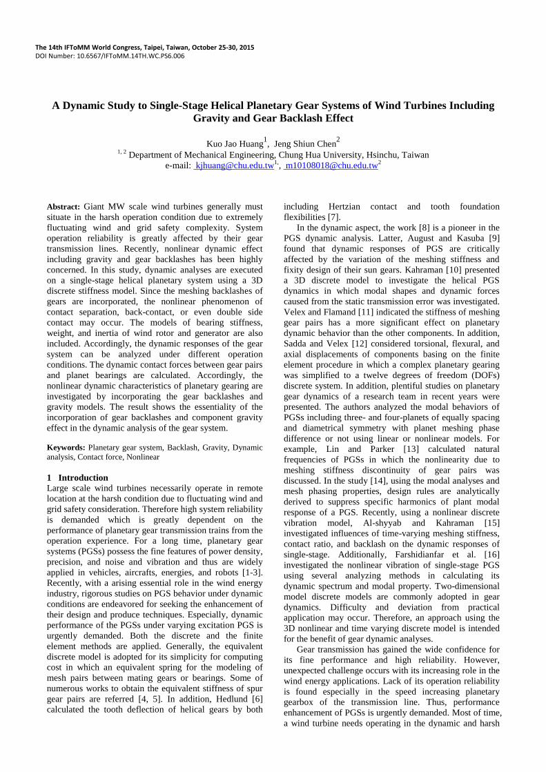
2 Configuration and Meshing Stiffness
Generally, PGSs are constituted by plural external sun-
planet gear pairs and internal planet-ring gear pairs. Figure
1(a) shows the configuration and components of a PGS
used in the transmission line for speed-up in wind turbines.
Figure 1(b) is its discrete analysis model. The ring gear is
fixed. The input shaft is coupled to the carrier and the
output shaft is connected to the sun gear for power output.
Fig. 1. (a) Configuration of PGS; (b) its discrete analysis model
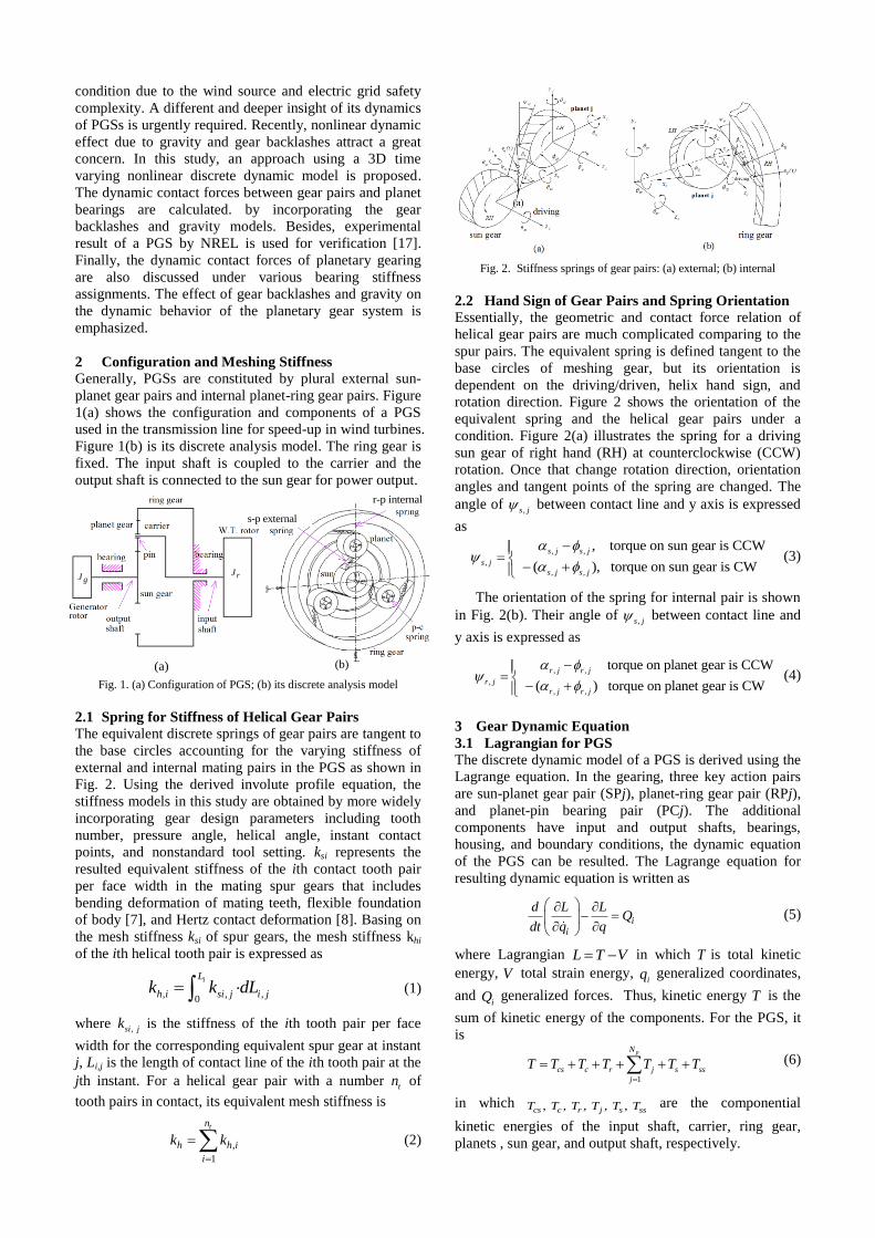
2.1 Spring for Stiffness of Helical Gear Pairs
The equivalent discrete springs of gear pairs are tangent to
the base circles accounting for the varying stiffness of
external and internal mating pairs in the PGS as shown in
Fig. 2. Using the derived involute profile equation, the
stiffness models in this study are obtained by more widely
incorporating gear design parameters including tooth
number, pressure angle, helical angle, instant contact
points, and nonstandard tool setting. ksi represents the
resulted equivalent stiffness of the ith contact tooth pair
per face width in the mating spur gears that includes
bending deformation of mating teeth, flexible foundation
of body [7], and Hertz contact deformation [8]. Basing on
the mesh stiffness ksi of spur gears, the mesh stiffness khi
of the ith helical tooth pair is expressed as
, , ,0
iL
h i si j i jk k dL (1)
where ,si jk is the stiffness of the ith tooth pair per face
width for the corresponding equivalent spur gear at instant
j, Li,j is the length of contact line of the ith tooth pair at the
jth instant. For a helical gear pair with a number tn of
tooth pairs in contact, its equivalent mesh stiffness is
,
1
tn
h h i
i
k k
(2)
Fig. 2. Stiffness springs of gear pairs: (a) external; (b) internal
2.2 Hand Sign of Gear Pairs and Spring Orientation
Essentially, the geometric and contact force relation of
helical gear pairs are much complicated comparing to the
spur pairs. The equivalent spring is defined tangent to the
base circles of meshing gear, but its orientation is
dependent on the driving/driven, helix hand sign, and
rotation direction. Figure 2 shows the orientation of the
equivalent spring and the helical gear pairs under a
condition. Figure 2(a) illustrates the spring for a driving
sun gear of right hand (RH) at counterclockwise (CCW)
rotation. Once that change rotation direction, orientation
angles and tangent points of the spring are changed. The
angle of ,s j between contact line and y axis is expressed
as
, ,
,
, ,
, torque on sun gear is CCW
( ), torque on sun gear is CW
s j s j
s j
s j s j
(3)
The orientation of the spring for internal pair is shown
in Fig. 2(b). Their angle of ,s j between contact line and
y axis is expressed as
, ,
,
, ,
torque on planet gear is CCW
( ) torque on planet gear is CW
r j r j
r j
r j r j
(4)
3 Gear Dynamic Equation
3.1 Lagrangian for PGS
The discrete dynamic model of a PGS is derived using the
Lagrange equation. In the gearing, three key action pairs
are sun-planet gear pair (SPj), planet-ring gear pair (RPj),
and planet-pin bearing pair (PCj). The additional
components have input and output shafts, bearings,
housing, and boundary conditions, the dynamic equation
of the PGS can be resulted. The Lagrange equation for
resulting dynamic equation is written as
ii
d L LQ
dt q q
(5)
where Lagrangian L T V in which T is total kinetic
energy, V total strain energy, iq generalized coordinates,
and iQ generalized forces. Thus, kinetic energy T is the
sum of kinetic energy of the components. For the PGS, it
is
1
pN
cs c r j s ss
j
T T T T T T T
(6)
in which , , , , ,cs c r j s ssT T T T T T are the componential
kinetic energies of the input shaft, carrier, ring gear,
planets , sun gear, and output shaft, respectively.
(a) (b)
rJgJ
r-p internal
s-p external
Then, V represents total strain energy from the
deformation parts in the PGS which is composed as
1
[ ( )]pN
cs cj rj sj ss
j
V V V V V V
(7)
where , , , ,cs cj rj sj ssV V V V V are the strain energies of the
components in the input shaft to carrier, planet-pin pairs,
ring-planet pairs, sun-planet pair, and output shaft,
respectively.
3.2 Rigid Body Motion and Elastic Deformation
The PGS dynamic model in this study can incorporate the
effect of rigid body motion. Here the rotational degree of
freedom corresponding to about the z axis is considered
since the other DOFs are stationary. Using the Lagrange
equation in Eq. (5), the equation of motion of the PGS
including rigid body motion effect is written as
1 1 1 1 1 1 1Μ X +C X + K X = F (8)
The subscript 1 denotes the equation used for a single
stage planetary gear system. M1, C1, K1, and F1 are
respectively the system mass, damping, stiffness, and
force terms. Also the displacement vector X1 of the gear
system is written as
1 1 2 ...
ps r n c R
X x x x x x x x (9)
Each elemental vector *x has six element representing its
three translation and there rotation DOFs as
* * *
T
* * * * x y zx y z x (10)
in which the subscript * denotes s, r, c, 1, 2,..,np, and c, R
for the corresponding parts. Then, the displacements in Eq.
(8) of the DOFs to the elastic deformation Xf and rigid
body motion XR are separately given as
0 0
0 0 0 0
ff fR f fff fff f
Rf RR R RR R
Μ Μ X FC KX X+ + =
Μ Μ X FX X (11)
where submatrices Mff and Kff are DOFs of deformation in
the PGS, MRR is accounting for the rigid DOFs. Also, MfR
and MRf is the coupling of elastic deformation and rigid
body motion which are given as
1 diag m m m m ... m m mpff ss s r p pN c cs
Μ (12)
T
Rf fRΜ Μ (13)
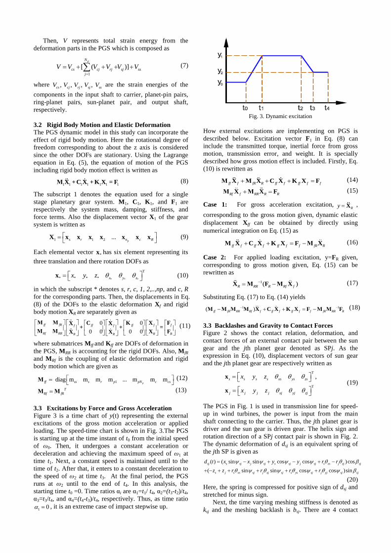
3.3 Excitations by Force and Gross Acceleration
Figure 3 is a time chart of y(t) representing the external
excitations of the gross motion acceleration or applied
loading. The speed-time chart is shown in Fig. 3.The PGS
is starting up at the time instant of t0 from the initial speed
of ω0. Then, it undergoes a constant acceleration or
deceleration and achieving the maximum speed of ω1 at
time t1. Next, a constant speed is maintained until to the
time of t2. After that, it enters to a constant deceleration to
the speed of ω2 at time t3. At the final period, the PGS
runs at ω2 until to the end of t4. In this analysis, the
starting time t0 =0. Time ratios αi are α1=t1/ t4, α2=(t3-t2)/t4,
α3=t3/t4, and α4=(t4-t3)/t4, respectively. Thus, as time ratio
1 0 , it is an extreme case of impact stepwise up.
Fig. 3. Dynamic excitation
How external excitations are implementing on PGS is
described below. Excitation vector F1 in Eq. (8) can
include the transmitted torque, inertial force from gross
motion, transmission error, and weight. It is specially
described how gross motion effect is included. Firstly, Eq.
(10) is rewritten as
ff f fR R ff f ff f f Μ X Μ X C X K X F (14)
Rf f RR R R Μ X Μ X F (15)
Case 1: For gross acceleration excitation,Ry X ,
corresponding to the gross motion given, dynamic elastic
displacement Xff can be obtained by directly using
numerical integration on Eq. (15) as
ff f ff f ff f f fR R Μ X C X K X F Μ X (16)
Case 2: For applied loading excitation, y=FR given,
corresponding to gross motion given, Eq. (15) can be
rewritten as
1( )R RR R Rf f
X Μ F Μ X (17)
Substituting Eq. (17) to Eq. (14) yields
1 1( )ff fR RR Rf f ff f ff f f fR RR R
Μ Μ Μ Μ X C X K X F Μ Μ F (18)
3.3 Backlashes and Gravity to Contact Forces
Figure 2 shows the contact relation, deformation, and
contact forces of an external contact pair between the sun
gear and the jth planet gear denoted as SPj. As the
expression in Eq. (10), displacement vectors of sun gear
and the jth planet gear are respectively written as
T
T
,s s s s xs ys zs
j j j j xj yj zj
x y z
x y z
x
x
(19)
The PGS in Fig. 1 is used in transmission line for speed-
up in wind turbines, the power is input from the main
shaft connecting to the carrier. Thus, the jth planet gear is
driver and the sun gear is driven gear. The helix sign and
rotation direction of a SPj contact pair is shown in Fig. 2.
The dynamic deformation of dsj is an equivalent spring of
the jth SP is given as
( ) ( sin sin cos cos )cos
( sin sin cos cos )sin
sj s sj j sj s sj j sj s zs j zj sj
s j s xs sj j xj sj s ys sj j yj sj sj
d t x x y y r r
z z r r r r
(20)
Here, the spring is compressed for positive sign of dsj and
stretched for minus sign.
Next, the time varying meshing stiffness is denoted as
ksj and the meshing backlash is bsj. There are 4 contact

conditions discussed as illustrated in Figs. 4(a)-4(d). Thus,
calculation of the dynamic contact forces is explained as:
(i) Regular contact (dsj >0): As shown in Fig. 4(a), the sun
gear drives the jth planet. In this kind of contact condition,
the meshing stiffness of sun-planet pair is modeled as
equivalent spring 1, ksj,1. The gear meshing follows the
action line a (blue). Thus, the dynamic meshing force is,
,1 ( )sj sj sjf k t d , ,1( )sj sjk k t (21)
(ii) No contact (dsj<0,sj sjd b ): As the gear pair has
backlash bsj, contact of the meshing pair may separate and
lose its contact as shown in Fig. 4(b). The equivalent
stiffness ksj=0. At the moment, no dynamic contact force
exists. Thus,
0sjf , 0sjk (22)
(iii) Back contact ( 0 , sj sj sjd d b ): As shown in Fig.
4(c), the tooth pair not only loses its regular contact but
also significantly rebounds such that the back
deformation is larger than the backlash bsj. Oppositely,
the sun gear drives the planet gear. Once that, the
backside of the planet tooth surface is driven by the
mating sun tooth. The equivalent meshing stiffness is the
spring 2, i.e., ksj=ksj,2. The meshing is along the action
line 2 (red). The meshing stiffness and direction of the
dynamic contact are different from that of the regular
contact. Then dynamic force of back contact condition is
( )( )sj sj sj sjf k t d b , ,2sj sjk k (23)
(iv) Double sides contact: Figure 4(d) shows the
condition of the double side contact which may occur
due to clearance, eccentricity, manufacturing errors, and
deformation. Once it appears, the wedge occurs. Both
the mesh condition incorporates both conditions of case
(i) and (ii), simultaneously. Thus, gear contact follows
action line 1 and 2 of regular and back contact
conditions. Two action lines have phase difference.
Dynamic force of two contacts are respectively given as
,1 ,1( )sj sj sjf k t d , ,2 ,2 ( )( )sj sj sj sjf k t d b (24)
(a) (b) (c)
(d)
(d) (e) (f)
Fig. 4. (a) Regular mesh; (b) mesh separation; (c ) back
contact; (d) action line and equivalent springs; (e) kinds of
mesh stiffness and mesh phase relation.
4 Results and Discussion
An example of PGS with three planets as the gearing type
shown in Fig. 1 is analyzed that is the first stage of a
speed-up gearbox used in 2.2MW wind turbines. The gear
data of the PGS are given as: teeth numbers of gears
zs=19, z
p=34, and z
r=89. The normal module mn = 16mm,
normal pressure angle αn=20o, helical angle β=7
o, face
width b=330mm. Its discrete analysis model was built and
shown in Fig. 1(b).
4.1 Transient Dynamic Response of PGS
The transient response without including gravity and
backlash effect is solved. A transmitted torque of 3×10⁵
Nm is exerted on the input shaft coupling with the carrier.
The moment inertia Jr on the input shaft is 87500kg·m2
and which on the sun gear is Jg=1600kg·m2. The operation
speeds of this analysis are assigned as ω1=60rpm and ω0
=ω2=0rpm. The total operation time is t4 =1.5s. Besides,
α1=α2, α3=1. The six DOFs of translational and angular
displacements of the second planet gear are shown in Fig.
5. Then, Figure 6 depicts the dynamic meshing forces
among the meshing pairs (SPj, RPj, PCj; i=1, 2, 3).
Fig. 5. Dynamic displacements of the 2nd planet gear.
(a) SP pair (b) RP pair
(c) PC pair (d) max contact force Fig. 6. Dynamic contact forces in meshing pairs: (a) SPj; (b)
RPj; (c) PCj.
4.2 Steady State Response of the PGS
A dynamic steady state result can be faster arrived by a
suitable initial condition assignment. In this analysis, the
initial values are assigned using the static deformation
caused by the applied torque and component weight. The
attained results are obviously same as the steady state
responses through a transient analysis to the steady state,
but much more computing cost is needed. When the static
bsj bsj

response is used to be the initial values, the steady state
responses can be efficiently achieved in 2 second. The
dynamic responses of three different conditions to gravity
and backlashes are solved. Figures 7 to 9 depict the
dynamic meshing forces among the meshing pairs under
the 3 condition considerations by different incorporation
of gravity and backlash effect. Figure 7 shows the result
without the gravity and clearance consideration. Under
that, the meshing of gear pair and bearing are regular.
Always, the meshing pairs remain continuous contact.
Thus, the dynamic response in Fig. 7 performs well. Then,
the result in Fig. 8 is the condition that gravity effect is
included but not the gear backlashes. In this analysis
condition, the deformation caused by static force of
gravity is combined with deformation from the applying
loading. Caused by gross rotation of the planet carrier,
static gravity has dynamic effect on the gear and bearing
pairs. Thus with its rotation proceeds, the dynamic
response is sine wave characteristic. It is shown below
that the low frequency sine wave deformation may make
the backlash effect occur. Figure 9 is the case of both
considering the gravity and clearance. Under that, the
dynamic effect of the gravity and backlash combines.
Separation or back contact in the meshing mating pairs
may occur. Once the contact of action pairs cannot
maintain, their contact forces disappear. These meshing
pairs are free constraint. The relative displacement of
meshing pair is large. Thus, a very big dynamic meshing
force may appear once the meshing pairs return a regular
contact since a sudden large contact force can be induced.
(a) SP pair (b) RP pair
(c) PC pair (d) max contact force
Fig. 7. Dynamic forces without gravity and clearance effect
(a) SP pair (b) RP pair
(c) PC pair (d) max dynamic force
Fig. 8. Dynamic forces with gravity but without backlash effect
(a) SP pair (b) RP pair
(c) PC pair (d) max dynamic force
Fig. 9. Dynamic forces with gravity and backlash effect
4.3 Result Verification by a NREL’s PGS
For verification, dynamic contact forces using the
proposed method are compared with the experimental
results of another gearbox in a 0.75MW wind turbine
which is heavily studied by NREL [18]. The first stage of
the gearing is a PGS (21-39-99). Gear data are below:
module mn=10mm and helical angle of 7.5o. The dynamic
contact forces of SPj and RPj pairs are given in Fig. 10(a)
and 10(b) which shows both the amplitudes and change
tendency are close. The analysis result of this study is
verified. Noticeably, the amplitudes of PCj pair are about
double of the NREL’s. Actually, they are rational since
designs of planet bearing supports of two studies are
different. The support of bearing design for plant gears in
this study is cantilevered, but it is a simply beam in
NREL’s.
(a) SP pair (b) RP pair
(c) PC pair (d) max dynamic force
Fig. 10. Analysis contact forces of meshing pairs of another PGS
compare with the experimental results of NREL
4.5 Various Bearing Stiffness Including Gravity and
Backlash
By incorporating the gravity and gear backlashes in PGSs,
the effect of bearing stiffness on the dynamic behavior is
discussed. Figure 11 depicts the dynamic contact forces of
the gear and bearing meshing pairs (SPj, RPj, PCj; j=1, 2,
3) by assigning various base values of bearing stiffness
which are 1e10, 1e11, and 1e12, respectively. The result
shows the nonlinear dynamic characteristic arisen from
the gear backlashes combining with gravity can be
diminished by increasing the bearing stiffness. The effect

of gravity inducing non-uniformity of the dynamic contact
forces due to sine wave change among the meshing pairs
(SPj, RPj, PCj) to the individual planet gears can be
reduced. Thus, the phenomenon of meshing separation or
back contact due to rebound of the gear and bearing pairs
has a higher opportunity to be avoided. For explanation,
the contact characteristic of SPj pair is discussed below.
As the showing in Fig. 11(a), the maximum dynamic
contact force of SPj pair is 460kN for the base value of
bearing stiffness of 1x10¹⁰
. Then, it is decreased to 370kN
for the base value of 1x10¹¹
in Fig. 11(b). It is even
decreased to 202kN for the value of 1x10¹²
. Under the
bigger value of 1x10¹²
, mesh separation or back contact in
mesh gear and bearing pairs caused by the combining
effect due to backlashes with the gravity become small.
The nonlinear phenomenon may not occur so as the form
of dynamic forces is similar to the result of case in Fig. 8
that only the gravity effect included. However, such large
a value of bearing stiffness of 1x10¹²
is almost impossible
to be realized in the gear design practice.
(a) Stiff=1e10 (b) Stiff=1e11
(c) Stiff=1e12 (d) max dynamic force
Fig. 11. Dynamic contact forces of different bearing stiffness
5 Conclusions
This study used a 3D discrete dynamic model of a helical
PGS in wind turbines under dynamic excitations
concerning the effect of change process of transmitted
loading and rotation speed. The dynamic contact forces
between gear pairs and planet bearings were resulted. The
discrete analysis model is formulated basing on the
equivalent springs for representation of varying meshing
stiffness of gear or bearing pairs. The physical models of
bearings, shafts, and housing frames were also
incorporated. After torque and rotation speed assigned,
dynamic transient and steady-state responses of the PGS
were analyzed. The dynamic contact forces between
meshing pairs of gears and bearings were resulted. The
analyzed contact forces of another PGS compared with the
experimental result by NREL. The proposed approach is
able to include models of bearing stiffness, weight, and
inertia of turbine rotor and generator. Accordingly,
dynamic responses of the planetary system are analyzed
under kinds of design considerations and operation
conditions. On the emphasis of gear backlashes and
gravity, the dynamic contact forces of planetary gearing
are discussed under different bearing stiffness assignments.
The result indicates that incorporation of gear mesh
backlashes with gravity effect is essential in the dynamic
study of the planetary gear system. The obtained and
further results are expected to be applied in wind turbines
concerning the dynamic excitation condition during the
design or operation phrases.
Acknowledgment
The authors would like to thank the financial support from
the National Science Council of Taiwan, R.O.C. under
grant MOST-102-2221-E-216-004.
References [1] C. Yuksel and A. Kahraman, “Dynamic Tooth Loads of Planetary
Gear Sets Having Tooth Profile wear,” Mechanism and Machine Theory, Vol. 39, pp. 695-715, 2004.
[2] A. Bajer and L. Demkowicz, “Dynamic Contact/ impact Problems, Energy Conservation, Planetary Gar Trains,” Computer Methods in Applied Mechanics and Engineering, Vol. 191, pp. 4159-4191, 2002.
[3] R. B. Parker and J. Lin, “Mesh Phasing Relationships in Planetary and Epicyclic Gears,” ASME Jo
[4] urnal of Mechanical Design, Vol. 126, pp.365-370, 2004.
[5] S. Du, R. B. Randall, and D. W. Kelly, “Modeling of spur gear mesh stiffness and static transmission error,” Proc. IMechE, Part C: J. Mechanical Engineering Science, vol. 212(4), pp 287-297, 1998.
[6] M. H. Arafa and M. M. Megahed, Evaluation of spur gear mesh compliance using the finite element method, Proc. IMechE, Part C: J. Mechanical Engineering Science, Vol. 213(6), pp.569-579,1999.
[7] A. L. Hedlund, “A parameterized numerical model for the evaluation of gear mesh stiffness variation of a helical gear pair,” Proc. IMechE, Part C: J. Mechanical Engineering Science, Vol. 222(7), pp.1321-1327, 2008.
[8] J. M. Matusz, W. J. O’Donnel and R. J. Erdlac, “Local Flexibility Coefficients for the Built-in Ends of Beams and Plates,” Journal of Engineering for Industry, pp. 607-614, 1969.
[9] Botman, M., “Epicyclic Gear Vibration,” ASME J. Eng. Ind., Vol. 17, pp. 811-815, 1976.
[10] R. August and R. Kasuba , “Torsional Vibrations and Dynamic Loads in a Basic Planetary Gear System,” J. Vib., Acoust. Stress Reliab. Des., Vol. 108, pp. 348-352, 1986.
[11] A. Kahraman, “Planetary gear train dynamics, ” ASME J. Mech. Des., Vol. 116(3), pp. 713-720, 1994.
[12] P. Velex, and L. Flamand, , “Dynamic response of planetary trains to mesh parametric excitations, ” ASME J. Mech. Des., 118(7), (1996), pp. 7-14.
[13] A. Saada and P.Velex, “An extended model for the analysis of the dynamic behavior of planetary trains, ” ASME J. Mech. Des., Vol. 117(2), pp 141-247, 1995.
[14] J. Lin and R. G. Parker, “Analytical characterization of the unique properties of planetary gear free vibration,” ASME J. Vibr. Acoust., Vol. 121(3), (1999), pp 316-321.
[15] Ambarisha,V. K., Parker, R. B. and Lin, J., “Suppression of planet mode response in planetary gear dynamics through meshing phasing, ” ASME J. Mech. Des., Vol. 128(2), pp 133-142, 2004.
[16] A. Al-shyyab, and A. Kahraman, “A non-linear dynamic model for planetary gear sets,” Proc. IMechE,” Part K:: J. Multi-body Dynamics, Vol. 221(4), ( 2007), pp 567-576.
[17] A. Farshidianfar, H. Moeenfard, and Rafsanjani A., “Frequency response calculation of no nlinear torsional vibration in gear systems,” Proc. IMechE, Part K: J. Multi-body Dynamics, Vol. 222(1), pp 49-60, 2008.
[18] R. Errichello, J. Muller, and M. Townsend, “Gearbox Reliability Collaborative Gearbox 1 Failure Analysis Report.” NREL/SR-5000-53062, 2011.