lcp dhhs. the dynamic helical hip system for proximal ...synthes.vo.llnwd.net/o16/llnwmb8/int...
TRANSCRIPT

LCP DHHS. The Dynamic Helical Hip System for Proximal Femur Fractures.
Surgical Technique
This publication is not intended for distribution in the USA.
Instruments and implants approved by the AO Foundation.

Image intensifier control
WarningThis description alone does not provide sufficient background for direct use of DePuy Synthes products. Instruction by a surgeon experienced in handling these products is highly recommended.
Processing, Reprocessing, Care and MaintenanceFor general guidelines, function control and dismantling of multi-part instruments, as well as processing guidelines for implants, please contact your local sales representative or refer to:http://emea.depuysynthes.com/hcp/reprocessing-care-maintenanceFor general information about reprocessing, care and maintenance of Synthes reusable devices, instrument trays and cases, as well as processing of Synthes non-sterile implants, please consult the Important Information leaflet (SE_023827) or refer to: http://emea.depuysynthes.com/hcp/reprocessing-care-maintenance
LCP DHHS Surgical Technique DePuy Synthes 1
Introduction
Surgical Technique
Product Information
MRI Information 32
Table of Contents
LCP Dynamic Helical Hip System (DHHS) 2
AO Principles 4
Indications 5
Preparation 6
Place Guide Wire 8
Determine Helix Blade Length 10
Ream 11
Assemble Helix Blade Inserter 12
Insert Helix Blade 14
Position Sideplate / Guide Shaft 17
Position Sideplate / Plate Impactor (optional) 18
Insert Screws 19
Lock Rotation / DHHS Impactor 19
Intraoperative Compression (optional) 20
Confirm Implant Placement 20
Implant Removal 21
Implants 22
Instruments 24
Set Lists 29

2 DePuy Synthes LCP DHHS Surgical Technique
The Locking Compression Plate (LCP) Dynamic Helical Hip System (DHHS) provides strong and stable internal fixa-tion of a variety of intertrochanteric, pertrochanteric and basilar neck frac-tures in which a stable medial buttress can be reconstructed. Additionally, implantation methods are simplified by minimized instrumentation.
DHHS Helix Blade The LCP DHHS helix blades easily glide within the LCP DHHS plate barrel for controlled collapse and impaction of fragments.
When the fracture requires additional intraoperative compression, the LCP DHHS Compression Screw can be used.
The LCP DHHS plates are low profile and have a limited-contact undersur-face for minimal soft tissue irritation.
The LCP DHHS plates are made of cold-worked 316L stainless steel.
Construct stability The helix blade improves resistance to cut-out and increases the rotational stability of the femoral head fragment when compared to traditional in-tertrochanteric lag screws.1
LCP DHHS. The Dynamic Helical Hip System for Proximal Femur Fractures.
1 M. Sommers, C. Roth, H. Hall, L. Ehmke, J. Krieg, S. Madey, and M. Bottlang, “Cut-Out Resistance of Implants for Intertrochanteric Fracture Fixation,” JOT, Vol 18, Number 6, July 2004.
LCP DHHS compression screw
Combi holes
Limited-contact undersurface

LCP DHHS Surgical Technique DePuy Synthes 3
The Combi holes in the LCP DHHS sideplate: – Combine a dynamic compression
unit (DCU) hole with a locking screw hole, allowing compression in the DCU section of the hole or locking screw fixation in the threaded sec-tion
– Provide directional compression and fixed-angle screw purchase
– Allow longitudinal screw angulation for lag screw fixation of medial frag-ments
– Allow 14° of transverse cortex screw angulation
– Are uniformly spaced to provide greater intraoperative flexibility for screw and/or wire or cable fixation
The LCP DHHS plate barrel contains a locking key. Two flats within the key correspond with the flats of the helix blade shaft. This enables the surgeon to manipulate the position of the side-plate prior to final fixation. Once the plate is positioned appropriately, the key may be locked, preventing any further rotation of the helix blade within the barrel.
No bone is removed from the femoral head before implantation of the helix blade. This creates a more stable and mechanically sound interface between the helix blade and bone.
The number of screw holes per plate length is maximized, without compro-mising plate strength. This allows an in-creased number of fixation points with a smaller incision.
Ease of use – Single-piece reamer does not need
adjustment prior to use – The helix blade does not have screw
threads and creates its own path as it is inserted, eliminating the need for a tap and reducing overall tor-sional forces on the femoral head during implantation
– Use of the helix blade inserter as-sembly reduces the overall operative time to implant the helix blade when compared to implanting conven-tional hip lag screws
– The self-contained, user-activated key mechanism of the LCP DHHS sideplate eliminates the need for ad-ditional instrumentation for intraop-erative insertion of separate antiro-tational locking devices within the barrel
Plate barrel Internal key mechanism

4 DePuy Synthes LCP DHHS Surgical Technique
AO Principles
In 1958, the AO formulated four basic principles which have become the guidelines for internal fixation.2 Those principles as applied to the LCP Dynamic Helical Hip System are:
Anatomic reduction The LCP DHHS sideplate and helix blade allow controlled col-lapse and interfragmentary compression while maintaining rotational control of the medial fragment.
Stable fixation Use of the helix blade provides improved rotational control of the femoral head fragment versus single-screw fixation, which results in improved life-to-cut-out. The number of screw holes per plate length is maximized to allow an increased number of fixation points. The locking screws in the plate shaft also create a fixed-angle construct, providing angular stability.
Preservation of blood supply The limited-contact design reduces plate-to-bone contact and vascular trauma. Use of the helix blade results in reduced bone removal compared to a standard hip screw.
Early, active mobilization Plate features combined with AO technique create an envi-ronment for bone healing, expediting a return to optimal function.
2 M.E. Müller, M. Allgöwer, R. Schneider, H. Willenegger: Manual of Internal Fixation, 3rd Edition. Berlin; Springer-Verlag. 1991.

LCP DHHS Surgical Technique DePuy Synthes 5
Indications
The LCP DHHS is indicated for the fol-lowing fractures of the proximal femur: – Intertrochanteric fractures – Basilar neck fractures – Pertrochanteric fractures
LCP DHHS is indicated for stable and unstable fractures in which a stable medial buttress can be reconstructed.

6 DePuy Synthes LCP DHHS Surgical Technique
1Preoperative planning
The size and angle of the plate as well as the length of the DHHS Blade can be determined preoperatively by using the DHS Goniometer (034.000.185).
Important: For a helix blade shorter than 85 mm, use a LCP DHHS short barrel sideplate.
Preparation

LCP DHHS Surgical Technique DePuy Synthes 7
4 Access
Make a straight lateral skin incision of 15 cm in length, starting two finger-widths proximal to the tip of the greater trochanter.
Split the iliotibial tract lengthwise. Detach the m. vastus later alis dorsally to the intramuscular membrane, retract ventrally and, if necessary, make a slight notch in the muscle in the region of the innominate tubercle. Expose the proxi-mal femoral shaft without retracting the periosteum.
3 Reduce fracture
If possible, reduce the fracture under the image intensifier by means of traction, abduction and internal rotation.
2Position patient
Place the patient in a supine position on the operating table.

8 DePuy Synthes LCP DHHS Surgical Technique
Barrel angle
1Place guide wire
Instruments
338.044 LCP DHHS Angled Guide, adjustable
338.000 DHS/DCS Guide Wire B 2.5 mm with threaded tip with trocar, length 230 mm
or900.723 Guide Wire B 2.5 mm with spade point tip, length 230 mm
Optional instrument
310.190 Drill Bit B 2.0 mm, length 100/75 mm, 2-flute
Fracture reduction should be done in the same manner as for a standard DHS procedure.
Determine anteversion by placing a new guide wire anteri-orly along the femoral neck. Insert the wire into the femoral head. The anteversion wire will later assist in correct place-ment of the central guide wire in the center of the femoral head.
The angle subtended between the femoral neck and shaft axis (C.C.D., or collum-center-diaphysis, angle) of the uninjured femur will aid in selection of the most appropriate barrel angle. The 135° barrel angle is most commonly indi-cated. The LCP DHHS plates are available with barrel angles of 130°, 135°, 140°, 145° and 150°.
Note: Greater barrel angles may produce biomechanical ad-vantages in unstable cases; i.e., better gliding characteristics and reduced bending stresses on the plate/barrel junction, although correct placement of the implant becomes techni-cally more difficult as the barrel angle increases.3
Position the DHHS angled guide at the desired angle.
Align the angled guide parallel to the axis of the femoral shaft and place it on the lateral cortex of the femur.
Note: The T-handle of the DHHS angled guide rotates 90° to a locked position, for easier use.
Place Guide Wire
3 P. Regazzoni, Th. Rüedi, R. Winquist, and M. Allgöwer, The Dynamic Hip Screw Implant System. Berlin: Springer-Verlag, 1985.

LCP DHHS Surgical Technique DePuy Synthes 9
Insert a new 2.5 mm guide wire through the angled guide, parallel to the anteversion wire and toward the center of the femoral head. The entry point varies with barrel angle. When the 135° barrel angle is used, the guide wire enters the prox-imal femur approximately 2.5 cm distal to the vastus ridge.
Predrilling of the lateral cortex with the 2.0 mm drill bit is recommended in dense bone.
Confirm placement of the guide wire under image intensifi-cation. It must lie along the axis of the femoral neck in both the anteroposterior (AP) and lateral views. The appropriate final position is in the center of the femoral head in both AP and lateral views. The tip of the guide wire should be a few millimeters short of the subchondral bony plate. When in-serted, the tip of the helix blade will coincide with the tip of the guide wire.
Note: This guide wire remains in place throughout the procedure. If the guide wire position is incorrect, remove the wire and insert a new 2.5 mm guide wire.
Remove and discard the anteversion wire.
38 mm
25 mm
10 DePuy Synthes LCP DHHS Surgical Technique
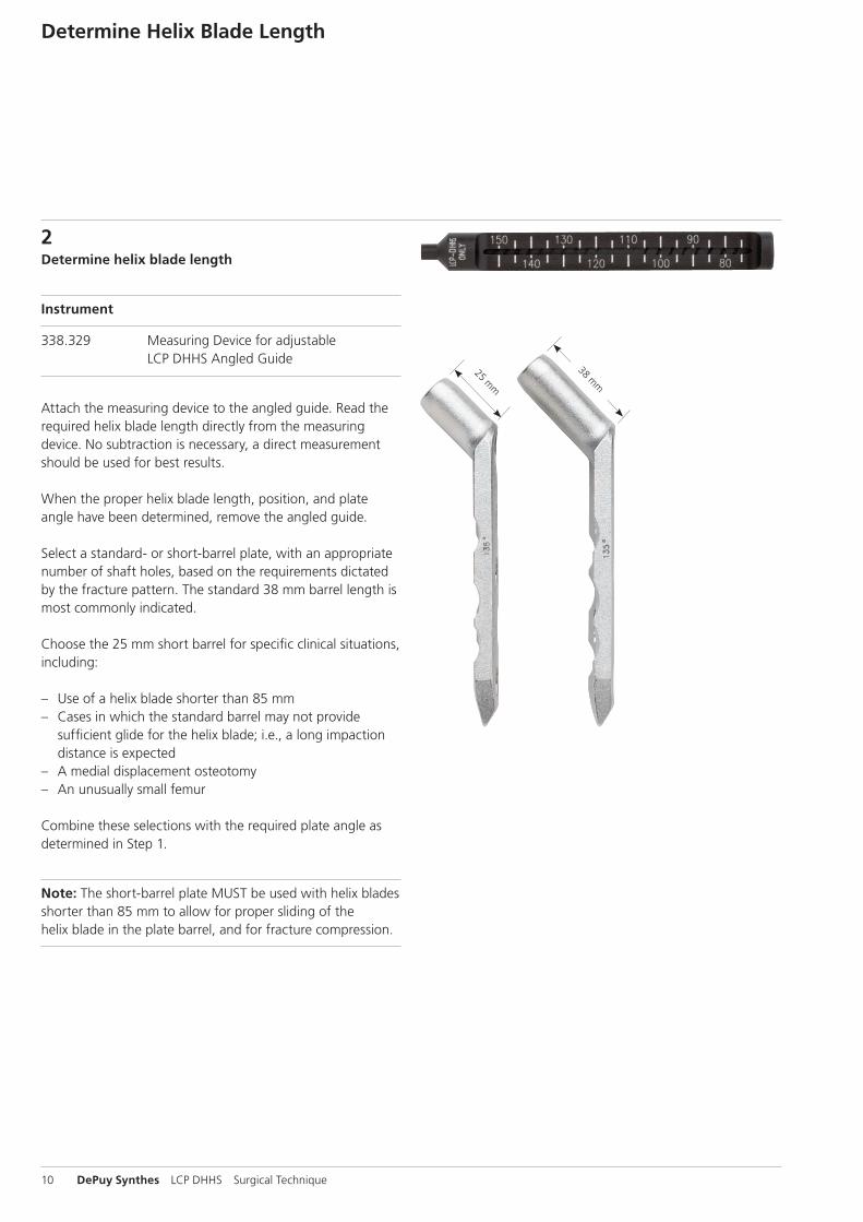
Determine Helix Blade Length
2Determine helix blade length
Instrument
338.329 Measuring Device for adjustable LCP DHHS Angled Guide
Attach the measuring device to the angled guide. Read the required helix blade length directly from the measuring device. No subtraction is necessary, a direct measurement should be used for best results.
When the proper helix blade length, position, and plate angle have been determined, remove the angled guide.
Select a standard- or short-barrel plate, with an appropriate number of shaft holes, based on the requirements dictated by the fracture pattern. The standard 38 mm barrel length is most commonly indicated.
Choose the 25 mm short barrel for specific clinical situations, including:
– Use of a helix blade shorter than 85 mm – Cases in which the standard barrel may not provide
sufficient glide for the helix blade; i.e., a long impaction distance is expected
– A medial displacement osteotomy – An unusually small femur
Combine these selections with the required plate angle as determined in Step 1.
Note: The short-barrel plate MUST be used with helix blades shorter than 85 mm to allow for proper sliding of the helix blade in the plate barrel, and for fracture compression.
LCP DHHS Surgical Technique DePuy Synthes 11
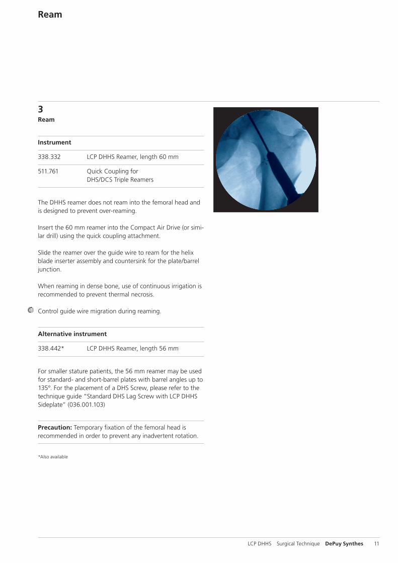
Ream
3Ream
Instrument
338.332 LCP DHHS Reamer, length 60 mm
511.761 Quick Coupling for DHS/DCS Triple Reamers
The DHHS reamer does not ream into the femoral head and is designed to prevent over-reaming.
Insert the 60 mm reamer into the Compact Air Drive (or simi-lar drill) using the quick coupling attachment.
Slide the reamer over the guide wire to ream for the helix blade inserter assembly and countersink for the plate/barrel junction.
When reaming in dense bone, use of continuous irrigation is recommended to prevent thermal necrosis.
Control guide wire migration during reaming.
Alternative instrument
338.442* LCP DHHS Reamer, length 56 mm
For smaller stature patients, the 56 mm reamer may be used for standard- and short-barrel plates with barrel angles up to 135°. For the placement of a DHS Screw, please refer to the technique guide “Standard DHS Lag Screw with LCP DHHS Sideplate” (036.001.103)
Precaution: Temporary fixation of the femoral head is recommended in order to prevent any inadvertent rotation.
*Also available

12 DePuy Synthes LCP DHHS Surgical Technique
align flats
Assemble Helix Blade Inserter
4Assemble helix blade inserter
Instruments
338.341 LCP DHHS Guide for Blade Insertion
338.345 LCP DHHS Connecting Screw, length 324 mm
338.346 LCP DHHS Spiral Inserter for Blade Insertion
Place the spiral inserter fully into the guide for blade inser-tion.
When assembling the helix blade inserter, align the flats of the helix blade with the flats on the sides of the guide. Insert the spiral inserter (back end) of the selected helix blade into the tip of the guide and orient the hexagonal recess of the helix blade onto the hexagonal tip of the spiral inserter.

LCP DHHS Surgical Technique DePuy Synthes 13
Insert the connecting screw into the back of the spiral in-serter (Figure 1) until the connecting screw knob is visible in the window at the back of the spiral inserter (Figure 2). Finger-tighten the connecting screw.
Note: Hold the helix blade and inserter assembly together with one hand, tilting the assembly downward. Use the free hand to insert and tighten the connecting screw.
Helix blade Inserter guide Coupling screw Inserter shaft
Figure 1
Figure 2

14 DePuy Synthes LCP DHHS Surgical Technique
Insert Helix Blade
5Insert helix blade
Instruments
338.341 LCP DHHS Guide for Blade Insertion
338.346 LCP DHHS Spiral Inserter for Blade Insertion
399.430 Hammer, 700 g
Before placing the insertion instrument into the reamed cavity, pull back on the spiral inserter so that only the helix is exposed. This ensures the helix blade is inserted to the proper depth and orientation. Place the inserter assembly over the guide wire and into the reamed cavity.
Note: Depending on whether the left or right hip is being treated, the corresponding “etch” on the helix inserter instrumentation should be visible.
Note: The swivel plate on the guide must be parallel with, and flush to, the shaft of the femur. This will determine the final position and depth of the helix blade.
swivel platehelix, starting position

LCP DHHS Surgical Technique DePuy Synthes 15
etch
Drive the helix blade into position using even and steady blows with the hammer. The spiral inserter assembly controls the depth and rotation of the helix blade.
Monitor the advancement of the helix blade under image intensification to ensure proper placement. When the helix blade is fully inserted, the inserter assembly will prevent any further advancement. Additionally, the circumferential etch around the spiral inserter will align with the back edge of the guide sleeve when the helix blade is fully implanted (Figure 1).
Figure 1

16 DePuy Synthes LCP DHHS Surgical Technique
Insert Helix Blade
5Insert helix blade
After full insertion of the helix blade, the inserter assembly can be removed by unscrewing the connecting screw and retracting the inserter assembly. The guide wire and the helix blade remain in the femur.
Optional instrument
314.270 Screwdriver, hexagonal, large, B 3.5 mm
The connecting screw may be loosened with a large (3.5 mm) hexagonal screwdriver, if necessary.

LCP DHHS Surgical Technique DePuy Synthes 17
Position Sideplate/Guide Shaft
6Position sideplate / guide shaft
Instruments
338.342 LCP DHHS Guide Shaft
338.347 LCP DHHS Impactor, cannulated
338.348 LCP DHHS Cap for Impactor
To place the LCP DHHS sideplate over the helix blade, the guide shaft must be used. Align the flats on the guide shaft with the flats of the internal key of the sideplate, then insert the guide shaft through the plate barrel.
Note: For a helix blade shorter than 85 mm, use an LCP DHHS short barrel sideplate.
Slide the sideplate and guide shaft over the guide wire. Insert the guide shaft into the back of the helix blade. The guide shaft has a hexagonal tip that mates with the end of the helix blade, to ensure that the internal sideplate key and the helix blade shaft are properly aligned.
Slide the sideplate down the guide shaft and onto the shaft of the helix blade.
Note: If the plate does not slide easily into the reamed cavity, gently moving the guide shaft up and down can assist in the placement.
After the plate has been fully seated into the reamed cavity, it may be aligned with the axis of the femur as needed. The internal plate key is free to rotate with no movement of the helix blade, until keyed.
When the barrel of the plate is fully inserted in the reamed cavity, remove the guide shaft.
If the sideplate is not completely flush against the lateral cortex, use of the LCP DHHS impactor with plastic cap may be necessary.

18 DePuy Synthes LCP DHHS Surgical Technique
Position Sideplate/Plate Impactor (optional)
7 Position sideplate/plate impactor (optional)
Instruments
338.347 LCP DHHS Impactor, cannulated
338.348 LCP DHHS Cap for Impactor
399.430 Hammer, 700 g
Alternative instrument
338.342 LCP DHHS Guide Shaft
To use the cap for impactor, slide it onto the tip of the can-nulated impactor until fully seated. A positive “click” will be noticed when assembling.
Place the cap for impactor and shaft assembly over the 2.5 mm guide wire and seat it directly into the barrel hole of the sideplate.
Use of light blows with the hammer is recommended until the sideplate is seated completely against the lateral cortex.
Precaution: Do not use the cap for impactor and shaft guide to seat the plate if the plate is more than 5 mm off the bone.
If the plate appears to be more than 5 mm off the bone, the flats on the helix blade and the internal flats on the key may not be properly aligned.
Impacting the plate in this condition could cause further unwanted advance ment of the helix blade.

LCP DHHS Surgical Technique DePuy Synthes 19
5.0 mm locking screw
4.5 mm cortex screw
Insert Screws and Lock Rotation/ Key Impactor
8Insert screws
Remove and discard the guide wire. Affix the LCP DHHS sideplate to the bone with 4.5 mm cortex screws, 5.0 mm locking screws, or a combination of both.*
9Lock rotation/DHHS impactor
Instruments
338.347 LCP DHHS Impactor, cannulated
399.430 Hammer, 700 g
Once the desired placement of the LCP DHHS sideplate has been achieved, the surgeon can use the cannulated impactor to advance the internal sideplate key and permanently lock rotation of the helix blade.
Note: Make sure to remove the plastic impactor tip before proceeding.
Insert the cannulated impactor into the barrel of the side-plate until it is fully seated. Moderate taps with the hammer will lock rotation, rendering the helix blade rotationally stable, but still allow dynamic collapse.
* For information on fixation principles using conventional and locked plating techniques, please refer to the LCP Locking Compression Plate Instructions for Use (036.000.019).

20 DePuy Synthes LCP DHHS Surgical Technique
9.7 mm LCP DHHS Enhanced Compression Screw
2.6 mm LCP DHHS Compression Screw
Intraoperative Compression (optional) and Confirm Implant Placement
10Intraoperative compression (optional) For further intraoperative compression of the trochanteric fracture, the LCP DHHS compression screw may be inserted in the helix blade. The LCP DHHS compression screw may be used in unstable fractures to prevent disengagement of the helix blade from the plate barrel in non-weightbearing patients.
Note: Use of the compression screw may cause the helix blade to pull out of osteoporotic bone.
11Confirm implant placement Take final C-arm images or x-rays to confirm proper implant placement.

LCP DHHS Surgical Technique DePuy Synthes 21
Implant Removal
Implant Removal
Instruments
03.010.058* Combined Hammer 400 g
03.010.059* Hammer Guide for Combined Hammer 400 g
314.118 Screwdriver Stardrive, T25, self-holding
314.270 Screwdriver, hexagonal, large, B 3.5 mm, with Groove
338.313 Connecting Screw B 5.2 mm
Use either the hexagonal or StarDrive screwdriver to remove any 4.5 mm cortex screws or 5.0 mm locking screws from the LCP DHHS sideplate.
Remove the LCP DHHS sideplate to expose the end of the helix blade. Once the sideplate has been removed, thread the connecting screw onto the end of the shaft of the helix blade. Thread the hammer guide for combined hammer onto the connecting screw. Use the combined hammer to extract the helix blade.
System Will remove:
DHS – DHS/DCS Wrench (338.060) – Connecing Screw, long (338.220)
DHS DHS One-Step DHHS
DHS One-Step – DHS/DCS Wrench, with octagonal coupling
(338.302) – Connecting Screw (338.310)
DHS One-Step DHHS
DHHS – Combined Hammer, 400 g (03.010.058) – Hammer Guide (03.010.059) – Connecting Screw B 5.2 mm (338.313)
DHHS
Note: If the DHHS Connecting Screw has external threads on the back-end, for removal use: Inserter-Extractor (356.490) and Slotted Hammer (332.200)*
Instrument options for removal
* The slide/fixed hammer and hammer guide can be found in the Titanium Humeral Nail-EX Instrument and Titanium Implant Set (01.001.300).
38 mm
25 mm
22 DePuy Synthes LCP DHHS Surgical Technique
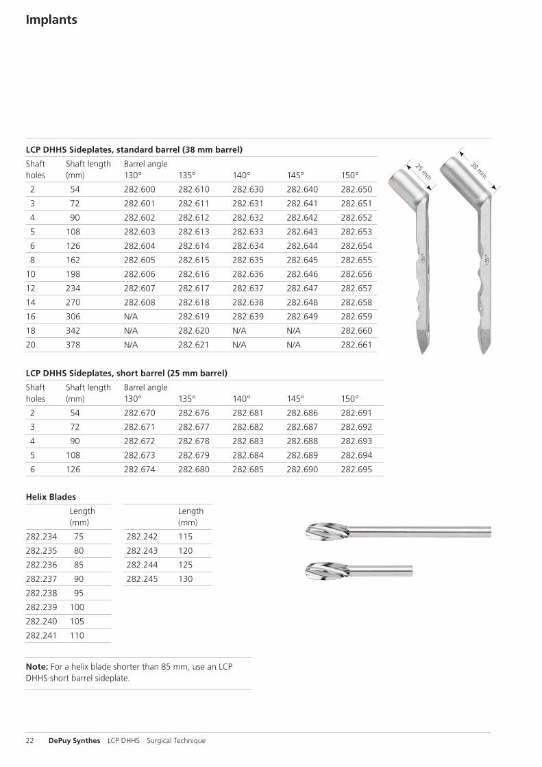
Implants
LCP DHHS Sideplates, standard barrel (38 mm barrel)
Shaft Shaft length Barrel angle holes (mm) 130° 135° 140° 145° 150°
2 54 282.600 282.610 282.630 282.640 282.650
3 72 282.601 282.611 282.631 282.641 282.651
4 90 282.602 282.612 282.632 282.642 282.652
5 108 282.603 282.613 282.633 282.643 282.653
6 126 282.604 282.614 282.634 282.644 282.654
8 162 282.605 282.615 282.635 282.645 282.655
10 198 282.606 282.616 282.636 282.646 282.656
12 234 282.607 282.617 282.637 282.647 282.657
14 270 282.608 282.618 282.638 282.648 282.658
16 306 N/A 282.619 282.639 282.649 282.659
18 342 N/A 282.620 N/A N/A 282.660
20 378 N/A 282.621 N/A N/A 282.661
LCP DHHS Sideplates, short barrel (25 mm barrel)
Shaft Shaft length Barrel angle holes (mm) 130° 135° 140° 145° 150°
2 54 282.670 282.676 282.681 282.686 282.691
3 72 282.671 282.677 282.682 282.687 282.692
4 90 282.672 282.678 282.683 282.688 282.693
5 108 282.673 282.679 282.684 282.689 282.694
6 126 282.674 282.680 282.685 282.690 282.695
Helix Blades
Length Length (mm) (mm)
282.234 75 282.242 115
282.235 80 282.243 120
282.236 85 282.244 125
282.237 90 282.245 130
282.238 95
282.239 100
282.240 105
282.241 110
Note: For a helix blade shorter than 85 mm, use an LCP DHHS short barrel sideplate.

LCP DHHS Surgical Technique DePuy Synthes 23
LCP DHHS Compression Screws
02.224.030 LCP DHHS Compression Screw, enhanced
211.890 LCP DHHS Compression Screw
02.102.001 DHS Trochanter Stabilizing Plate, universal, locking

24 DePuy Synthes LCP DHHS Surgical Technique
Instruments
310.431 Drill Bit B 4.3 mm, length 180 mm
310.440 Drill Bit B 4.5 mm, length 145/120 mm
311.440 T-Handle with Quick Coupling
311.460 Tap for Cortex Screws B 4.5 mm
312.449 Threaded Drill Guide 4.3
310.310 Drill Bit B 3.2 mm, length 145/120 mm

LCP DHHS Surgical Technique DePuy Synthes 25
312.460 Double Drill Guide 4.5/3.2
312.480 Drill Sleeve Insert 4.5/3.2
314.110 Holding Sleeve, large
314.118 Screwdriver Stardrive, T25, self-holding
314.119 Screwdriver Shaft Stardrive 4.5/5.0, T25
314.150 Screwdriver Shaft, hexagonal, large, B 3.5 mm

26 DePuy Synthes LCP DHHS Surgical Technique
Instruments
314.270 Screwdriver, hexagonal, large, B 3.5 mm
319.100 Depth Gauge for Screws B 4.5 to 6.5 mm
319.970 Screw Forceps, self-holding
323.460 Universal Drill Guide 4.5/3.2
338.044 LCP DHHS Angled Guide, adjustable

LCP DHHS Surgical Technique DePuy Synthes 27
338.313 Connecting Screw B 5.2 mm
338.329 Measuring Device for adjustable LCP DHHS Angled Guide
338.332 LCP DHHS Reamer, length 60 mm
338.341 LCP DHHS Guide for Blade Insertion
338.342 LCP DHHS Guide Shaft
338.345 LCP DHHS Connecting Screw, length 324 mm

28 DePuy Synthes LCP DHHS Surgical Technique
Instruments
338.346 LCP DHHS Spiral Inserter for Blade Insertion
338.347 LCP DHHS Impactor, cannulated, length 300 mm
338.348 LCP DHHS Cap for Impactor
399.430 Hammer 700 g
511.761 Quick Coupling for DHS/DCS Triple Reamers
338.000 DHS/DCS Guide Wire B 2.5 mm with threaded tip with trocar, length 230 mm
or900.723 Guide Wire B 2.5 mm with spade point
tip, length 230 mm

LCP DHHS Surgical Technique DePuy Synthes 29
LCP DHHS Implant Set (105.387)
Graphic Case 690.326 Graphic Case for LCP DHHS Implants
Implants* 211.890 LCP DHHS Compression Screw
Helix Blades
Length Length (mm) Qty. (mm) Qty.
282.234 75 2 282.240 105 3
282.235 80 2 282.241 110 2
282.236 85 2 282.242 115 2
282.237 90 3 282.243 120 2
282.238 95 3 282.244 120 2
282.239 100 3 282.245 130 2
LCP DHHS Sideplates, standard barrel*
Barrel Shaft Shaft Length Angle Holes (mm) Qty.
282.602 130° 4 90 1
282.603 130° 5 108 1
282.604 130° 6 126 1
282.610 135° 2 54 3
282.611 135° 3 72 2
282.612 135° 4 90 3
282.613 135° 5 108 2
282.614 135° 6 126 2
282.630 140° 2 54 1
282.631 140° 3 72 1
282.632 140° 4 90 1
282.633 140° 5 108 1
282.634 140° 6 126 1
282.640 145° 2 54 1
282.641 145° 3 72 1
282.642 145° 4 90 1
282.643 145° 5 108 1
282.644 145° 6 126 1
Note: For additional information, please refer to package insert. *For additional LCP DHHS sideplates, see page 22.

30 DePuy Synthes LCP DHHS Surgical Technique
LCP DHHS Basic Set (105.388)
Graphic Case
690.325 Graphic Case for LCP DHHS Instruments
Instruments 310.310 Drill Bit B 3.2 mm, length 145/120 mm, 2-flute310.431 Drill Bit B 4.3 mm, length 180 mm310.440 Drill Bit B 4.5 mm, length 145/120 mm, 2-flute311.440 T-Handle with Quick Coupling311.460 Tap for Cortex Screws Ø 4.5 mm312.449 Threaded Drill Guide 4.3312.460 Double Drill Guide 4.5/3.2314.110 Holding Sleeve, large314.118 Screwdriver Stardrive, T25, self-holding314.119 Screwdriver Shaft Stardrive 4.5/5.0, T25314.150 Screwdriver Shaft, hexagonal, large,
B 3.5 mm314.270 Screwdriver, hexagonal, large, B 3.5 mm319.100 Depth Gauge for Screws B 4.5 to 6.5 mm319.970 Screw Forceps, self-holding338.044 LCP DHHS Angled Guide, adjustable338.313 Connecting Screw B 5.2 mm338.329 Measuring Device for adjustable LCP DHHS
Angled Guide338.332 LCP DHHS Reamer, length 60 mm338.341 LCP DHHS Guide for Blade Insertion338.342 LCP DHHS Guide Shaft338.345 LCP DHHS Connecting Screw,
length 324 mm338.346 LCP DHHS Spiral Inserter
for Blade Insertion338.347 LCP DHHS Impactor, cannulated,
length 300 mm338.348 LCP DHHS Cap for Impactor399.430 Hammer 700 g511.761 Quick Coupling for DHS/DCS Triple
Reamers338.000 DHS/DCS Guide Wire B 2.5 mm with threaded tip with trocar, length 230 mm or900.723 Guide Wire B 2.5 mm with spade point
tip, length 230 mm

LCP DHHS Surgical Technique DePuy Synthes 31
Implants
5.0 mm Locking Screws, self-tapping, with T25 StarDrive recess
Length Length (mm) Qty. (mm) Qty.
212.201 14 4 212.212 36 4
212.202 16 4 212.213 38 4
212.203 18 2 212.214 40 4
212.204 20 2 212.215 42 4
212.205 22 2 212.216 44 4
212.206 24 2 212.217 46 2
212.207 26 2 212.218 48 2
212.208 28 2 212.219 50 2
212.209 30 2 212.220 55 2
212.210 32 4 212.221 60 2
212.211 34 4
4.5 mm Cortex Screws, self-tapping, with 3.5 mm hexagonal recess
Length Length (mm) Qty. (mm) Qty.
214.828 28 3 214.842 42 6
214.830 30 3 214.844 44 6
214.832 32 6 214.846 46 3
214.834 34 6 214.848 48 3
214.836 36 6 214.850 50 3
214.838 38 6 214.852 52 3
214.840 40 6 214.854 54 3
Also Available02.102.001 DHS Trochanter Stabilizing Plate, universal,
locking02.224.030 LCP DHHS Compression Screw, enhanced03.010.058 Combined Hammer 400 g03.010.059 Hammer Guide for Combined Hammer
400 g034.000.185 DHS Goniometer338.333 LCP DHHS Reamer338.442 LCP DHHS Reamer, length 56 mm

32 DePuy Synthes LCP DHHS Surgical Technique
MRI Information
Torque, Displacement and Image Artifacts according to ASTM F 2213-06, ASTM F 2052-06e1 and ASTM F2119-07Non-clinical testing of worst case scenario in a 3 T MRI system did not reveal any relevant torque or displacement of the construct for an experimentally measured local spatial gradient of the magnetic field of 3.69 T/m. The largest image artifact extended approximately 169 mm from the construct when scanned using the Gradient Echo (GE). Testing was conducted on a 3 T MRI system.
Radio-Frequency-(RF-)induced heating according to ASTM F2182-11aNon-clinical electromagnetic and thermal testing of worst case scenario lead to peak temperature rise of 9.5 °C with an average temperature rise of 6.6 °C (1.5 T) and a peak temperature rise of 5.9 °C (3 T) under MRI Conditions using RF Coils [whole body averaged specific absorption rate (SAR) of 2 W/kg for 6 minutes (1.5 T) and for 15 minutes (3 T)].
Precautions: The above mentioned test relies on non-clin-ical testing. The actual temperature rise in the patient will depend on a variety of factors beyond the SAR and time of RF application. Thus, it is recommended to pay particular attention to the following points: – It is recommended to thoroughly monitor patients under-
going MR scanning for perceived temperature and/or pain sensations.
– Patients with impaired thermo regulation or temperature sensation should be excluded from MR scanning proce-dures.
– Generally it is recommended to use a MR system with low field strength in the presence of conductive implants. The employed specific absorption rate (SAR) should be reduced as far as possible.
– Using the ventilation system may further contribute to reduce temperature increase in the body.


0123
Synthes GmbHEimattstrasse 34436 OberdorfSwitzerlandTel: +41 61 965 61 11Fax: +41 61 965 66 00www.depuysynthes.com
This publication is not intended for distribution in the USA.
All surgical techniques are available as PDF files at www.depuysynthes.com/ifu ©
DeP
uy S
ynth
es T
raum
a, a
div
isio
n of
Syn
thes
Gm
bH. 2
015.
A
ll rig
hts
rese
rved
. 03
6.0
00.
738
DSE
M/T
RM
/111
4/02
22(2
) 11
/15