a decentralised system approach for controlling agvs with...
TRANSCRIPT
A Decentralised System Approachfor Controlling AGVs with ROS
Robert Walenta Twan Schellekens
AGVR GmbHAuf der Hüls 197Aachen, Germany
Alexander Ferrein Stefan Schiffer
The Mobile Autonomous Systemsand Cognitive Robotics Institute
FH Aachen University of Applied SciencesAachen, Germany
Abstract—The current industrial state of the art for automatedguided vehicles relies on centralised controllers dispatchingtransports to vehicles along predefined paths. The design of thesepaths is time-consuming and has to be done in advance, followedby an extensive testing phase. In the field of mobile robotics,robust path planning and navigation algorithms exist. However,they have not yet found their way into industrial applications inlarger numbers. In this paper, we present a system architecturefor a decentralised control of multiple automated guided vehiclesperforming material transportation tasks in intra-logistic appli-cations which is based on mobile robotics solutions. The proposedsystem includes solutions for self-localisation, behaviour control,conflict-free routing and motion control. The non-centralisedcontrol of the system architecture allows for dynamic pathplanning and traffic coordination. Its implementation is based onthe Robot Operating System, the de-facto standard middlewarefor robotics applications. We give an overview of the overallsystem architecture as well as the coordination mechanisms andshow a first proof of concept in simulations.
I. INTRODUCTION
Changing product lines, customised products and sophisti-cated production requirements demand flexible, adaptive andintelligent industrial manufacturing systems. The complexityof these systems is especially challenging for intra-logisticprocesses. Intra-logistics describes the organisation, realisationand optimisation of internal material flow. This requires ef-ficient material transportation, which presumes non-blockingand non-empty runs.
Therefore, the use of automated guided vehicles (AGV) hasbeen well-established in the last decades. AGVs are automatedmobile platforms and are used since the 1950s for repeti-tive material handling tasks in industrial manufacturing andwarehouse systems [1]. Running 24/7, AGVs are increasingthe productivity while reducing labour costs. Their endurance,precision and reliability are ensuring predictable and traceableintra-logistic processes. Additionally, high safety standardsare circumventing serious harm to human workers and helpavoiding damages to the facility.
Simple transport tasks are usually rare in industrial appli-cations. More common are requirements demanding for highpayloads up to 65 t, sophisticated pick-and-drop handling,
high flow rates, temperature ranges between −27 ◦C to 50 ◦C,indoor and outdoor use cases and collaborative applications.In the past few years, the topic of Industry 4.0 becomes evermore important for the field of intra-logistics. The goal hereis to have AGV systems fully integrated with the existing ITsystems. Therefore, a new degree of autonomy is requiredwhich enables operating the fleet of UGVs from the officedesk [2].
AGVs are designed to follow predefined tracks, similar totrains that are moving along the rails. These tracks are basedon magnet- or inductive guide tapes, implemented on or inthe site floor. This rather old-fashioned approach is still usedin industrial applications, but is currently being replaced byvirtual tracks designed in CAD programs based on the 2Dlayouts of the facility. These methods have a long preparationand implementation time, including a thorough testing phaseat the facility site. This further increases the implementationcost. As a consequence common AGV systems are not flexiblein adapting to changes. Also, their ability to perceive theenvironment is limited, so simple errors can lead to materialflow interrupts.
In this paper, we propose a novel system concept that allowsa higher degree of autonomy and enables the implementationof current developments for industrial usage. Our approachcomes with more flexibility in the path planning and, hence, itis easier to adapt the approach to changes in the environment.The implementation is based on several standard packages thatcomes with the Robot Operating System (ROS), on the onehand; on the other hand, it relies on a number of custom-buildpath planning and routing algorithms which are tailored to theintralogistics scenario.
The rest of the paper is organised as follows. In the nextsection, we give an overview of different AGV types that areused in industrial intra-logistics applications and review somerelated approaches. In Section III, we give a brief introductionto the Robot Operating System, which the implementationof our approach is based on. In Section IV we present thearchitecture of our non-centralised control system before weconclude.

II. AUTOMATED GUIDED VEHICLE
AGVs are deployed in a number of different applicationdomains and the range of vehicle types has increased alongsidecustomers’ needs. Primary applications are in manufactur-ing, warehousing, automotive, chemical, paper-print, food andhealthcare industry. The variety of applications specify thegeneral system requirements, such as size, load-capacity, load-mechanism, navigation constraints, the number of deployedvehicles, and type of the environment. In the following, wediscuss the different requirements.
The load is the most crucial requirement for materialtransportation and differ due to the use-case in size andshape, where the weight can raise up 65 t. AGVs are thereforeoperating as a unit-loader or as a mobile manipulator. If onlytransportation of goods is required, the AGV is either loadedmanually or by some automatic equipment. If interaction withstands or conveyors is needed, an effector will perform thematerial handling. For handling tasks where palletisation isnot possible, effectors like clamps or industrial robots handlerolls, boxes and other raw materials. Otherwise, actuatedforks lift and drop material units are deployed. Regardingthe position accuracy when manipulating materials, usuallyonly low tolerances within 10mm or less are allowed. Thisconstrains, in particular, the localisation system, but also hasan influence on the type of kinematic drive chosen. Well-established are localisation systems relying on reflector bea-cons operating with a positioning accuracy of 4mm [3]. Thetype of kinematic drive depends on the mass distribution, therequired accuracy and the degree of freedom needed. Commonin industrial applications are kinematic systems based on atricycle or differential drive, skid steering or asynchronousdrive mechanisms. In practice, the amount of actuated wheelsis limited to reduce cost and, hence, increase the profitabilityof the system.
Automated guided vehicles (AGVs) is a rather long-established discipline in mechanical engineering. A quick webresearch yields numerous patents and a large number of pub-lications from the 80’s and the 90’s. There are also a numberof successful industrial players around who offer AGVs onthe market for intra-logistics automation in production linesor warehouses. The market share of USD 810 million in theUSA in 2015 is expected to grow by 7.3 % until 2024, as thesummary of a market forecast suggests [4]. The technologyused in many solutions is rather conservative using magneticstripes on the shop-floor etc. On the other hand, in the lastdecade or so, many new innovative solutions appeared onthe market that make use of mobile robotics technology.One of them is the KIVA system [1], now amazonrobotics.There, hundreds of so-called pods, small robots that can pickup inventory shelves, drive through a warehouse and bringthe shelves to pick workers who commission online orders.Another rather novel approach is taken by Fetch Robotics.Founded in 2014 by a former Willow Garage employee, theyjust presented their latest development: the Freight500 (see,for instance, [5]). It resembles very much the Clearpath OTTO
robot (e.g. [6]). What both these systems have in common isthat they make use of the Robot Operating System [7] for theirintelligent control software, as Melonee Wise, the founder ofFreight Robotics, explains in an interview with the IndustrialRobot Journal [8].
As our approach is likewise based on ROS, we outline theRobot Operating System in the next section.
III. THE ROBOT OPERATING SYSTEM
To implement a navigation system which fulfils the re-quirements of an industrial material transportation system,a software system has to be designed that is capable ofcoordinating all vehicles in the system, ensuring a conflict-free travelling and performing material handling actions. Todo so, methods are required to localize the vehicle, perceivethe environment and plan optimal paths through the environ-ment. Additionally, a hardware abstraction layer is required toenable the communication with sensors and actuators. A driversoftware on top has to interface with high-level applications.This enables an evaluation of sensor readings and to control therobot system. ROS is an open-source middleware for roboticplatforms. ROS provides all necessary features of an operatingsystem and enables the development of applications in C++and Python. ROS is published under the BSD license, allowingfor commercial use of ROS [9]. It provides a large open-sourcerobotics library with state-of-the-art solutions for roboticstasks such as localisation, path planning, image processing,collision avoidance and motion control. The ROS runtimeenvironment manages the execution of applications and theinter-process communication. One of the basic goals of ROSis to enable small, mostly independent programs called nodesthat all run at the same time and can be executed on differentmachines. That concept allows for a modularisation and acomputational distribution [10].
IV. CONTROL SYSTEM OVERVIEW
A. System Outline
The control system is implemented completely in ROS. Wemade use of a number of already existing ROS componentsand integrated them with some packages tailor-made for theAGVR. Fig. 1 gives an overview of the overall system architec-ture. The control system consists of the following components:
• Warehouse Management System (WMS)• Action Level Execution Agent (ALEA)• Navigation Graph (NavGraph)• ROS Move-Base (MoveBase)• Time Elastic Band planner (TEB)In the following, we describe the different components in
detail and refer to their ROS implementations.1) WMS: The Warehouse Management System controls the
movement and the storage of materials within the warehouse.It is optimising the fragmented material storage by utilisingthe available resources making use of the current input andoutput demand. This is stimulating the material flow andso the transport system. Transport orders are published and

Fig. 1: The overall system components
broadcasted to every transport vehicle. To deal with networkissues all orders are stored on the AGVs itself.
2) ALEA: The Action Level Execution Agent is a be-haviour controller which is monitoring the state of the AGVand controlling primitive actions such as pick, drop, gotoor chargeBattery. It is continuously listening to broadcastedorders and selects the optimal order by priority, occurrence,distance and time constraints. Knowing the position and theassignment of all orders, ALEA assists in ensuring a blockingand deadlock-free traffic. So when priority or traffic statecompetitions determine a better vehicle assignment, order re-allocation or “stealing” actions can be performed to improvethe material flow performance.
3) NavGraph: The NavGraph is a topological graph-basedroute planner, initially developed for the robotic softwareframework Fawkes [11]. The navigation graph consists ofnodes, segments and station elements (Fig. 2). In this work thegraph is based on bidirectional segments to enable a flexibletraffic flow. Each graph element is capable to hold propertiesthat can either influence the behaviour controller or the pathplanning itself.
4) Navigation Stack: The ROS Navigation Stack is a soft-ware collection for self-localisation, path planning and motioncontrol. Core application is the ROS move_base package.move_base is implemented as an ROS action, giving a goal,it will attempt to reach the destination using odometry and
Fig. 2: Topological Graph
other sensor readings while sending velocity commands to themobile robot base [12].
These are the base components for navigating the AGV withROS. In the following we go more into the details on thenavigation system.
B. Navigation Graph
A central component of the control architecture is the Nav-igation Graph package for allowing dynamic and flexible pathplanning. The NavGraph package was extended to coordinatethe AGV fleet and is executed on each vehicle to achieve adecentralised system. Therefore inter-vehicle communicationis required to exchange information and the current statebetween the vehicles. Considering upcoming traffic conflicts,the same rules are defined on each vehicle to ensure that everyAGV comes up with the same solution. In the following wegive more details on the mechanisms behind this concept.
NavGraph can annotate each graph element with con-straints. Such constraints have a direct effect on the pathplanning and can, for example, force a vehicle to drive onlyforwards. Based on the navigation graph, an A* search isperformed to determine the optimal path between a source anddestination node. Through the inter-vehicle communication,NavGraph considers priority, current position, desired path andthe final goal of each vehicle. Checking all published routes,NavGraph evaluates possible encounterings of vehicles. Basedon a priority competition NavGraph decides, which vehicle hasthe right of way. This approach is based on [13].
NavGraph distinguishes between two phases for executinga NavGraph goal, an offline and an online phase. The formerdescribes the period before the plan execution. Here, theNavGraph package determines plans with or without partic-ular path constraints. The path without particular constraintsrepresents the shortest possible route to the goal, a constrainedpath is considering blockings and cost increasing factors likespeed or turning rates and represents a plan with possibledetours that have to be taken. NavGraph trades off betweenthe unconstrained and constrained path calculating a normeddifference and relates the unconstrained plan as the reference
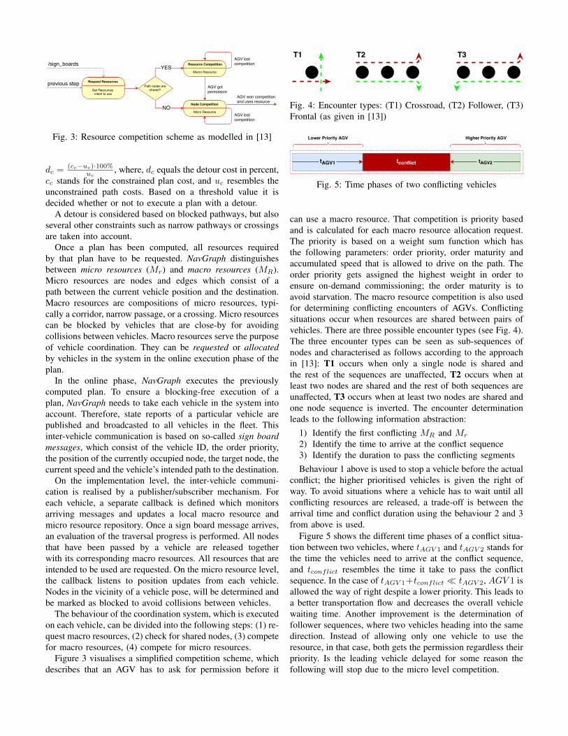
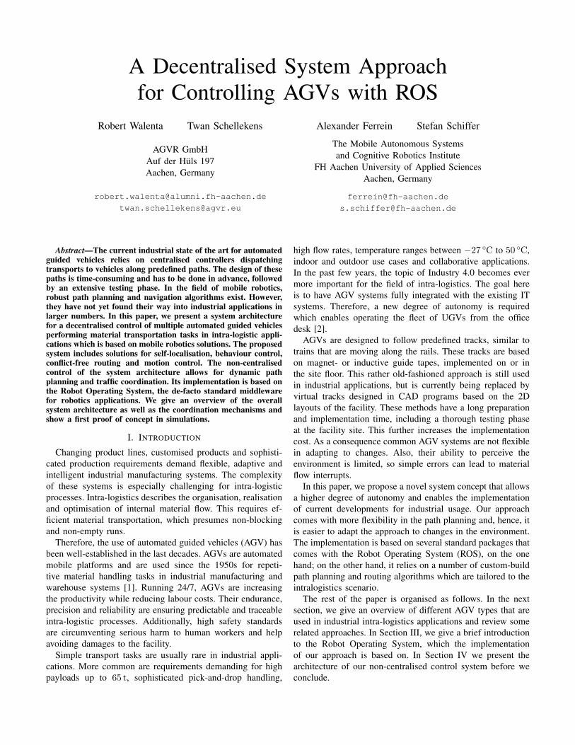
Fig. 3: Resource competition scheme as modelled in [13]
dc =(cc−uc)·100%
uc, where, dc equals the detour cost in percent,
cc stands for the constrained plan cost, and uc resembles theunconstrained path costs. Based on a threshold value it isdecided whether or not to execute a plan with a detour.
A detour is considered based on blocked pathways, but alsoseveral other constraints such as narrow pathways or crossingsare taken into account.
Once a plan has been computed, all resources requiredby that plan have to be requested. NavGraph distinguishesbetween micro resources (Mr) and macro resources (MR).Micro resources are nodes and edges which consist of apath between the current vehicle position and the destination.Macro resources are compositions of micro resources, typi-cally a corridor, narrow passage, or a crossing. Micro resourcescan be blocked by vehicles that are close-by for avoidingcollisions between vehicles. Macro resources serve the purposeof vehicle coordination. They can be requested or allocatedby vehicles in the system in the online execution phase of theplan.
In the online phase, NavGraph executes the previouslycomputed plan. To ensure a blocking-free execution of aplan, NavGraph needs to take each vehicle in the system intoaccount. Therefore, state reports of a particular vehicle arepublished and broadcasted to all vehicles in the fleet. Thisinter-vehicle communication is based on so-called sign boardmessages, which consist of the vehicle ID, the order priority,the position of the currently occupied node, the target node, thecurrent speed and the vehicle’s intended path to the destination.
On the implementation level, the inter-vehicle communi-cation is realised by a publisher/subscriber mechanism. Foreach vehicle, a separate callback is defined which monitorsarriving messages and updates a local macro resource andmicro resource repository. Once a sign board message arrives,an evaluation of the traversal progress is performed. All nodesthat have been passed by a vehicle are released togetherwith its corresponding macro resources. All resources that areintended to be used are requested. On the micro resource level,the callback listens to position updates from each vehicle.Nodes in the vicinity of a vehicle pose, will be determined andbe marked as blocked to avoid collisions between vehicles.
The behaviour of the coordination system, which is executedon each vehicle, can be divided into the following steps: (1) re-quest macro resources, (2) check for shared nodes, (3) competefor macro resources, (4) compete for micro resources.
Figure 3 visualises a simplified competition scheme, whichdescribes that an AGV has to ask for permission before it
Fig. 4: Encounter types: (T1) Crossroad, (T2) Follower, (T3)Frontal (as given in [13])
Fig. 5: Time phases of two conflicting vehicles
can use a macro resource. That competition is priority basedand is calculated for each macro resource allocation request.The priority is based on a weight sum function which hasthe following parameters: order priority, order maturity andaccumulated speed that is allowed to drive on the path. Theorder priority gets assigned the highest weight in order toensure on-demand commissioning; the order maturity is toavoid starvation. The macro resource competition is also usedfor determining conflicting encounters of AGVs. Conflictingsituations occur when resources are shared between pairs ofvehicles. There are three possible encounter types (see Fig. 4).The three encounter types can be seen as sub-sequences ofnodes and characterised as follows according to the approachin [13]: T1 occurs when only a single node is shared andthe rest of the sequences are unaffected, T2 occurs when atleast two nodes are shared and the rest of both sequences areunaffected, T3 occurs when at least two nodes are shared andone node sequence is inverted. The encounter determinationleads to the following information abstraction:
1) Identify the first conflicting MR and Mr
2) Identify the time to arrive at the conflict sequence3) Identify the duration to pass the conflicting segmentsBehaviour 1 above is used to stop a vehicle before the actual
conflict; the higher prioritised vehicles is given the right ofway. To avoid situations where a vehicle has to wait until allconflicting resources are released, a trade-off is between thearrival time and conflict duration using the behaviour 2 and 3from above is used.
Figure 5 shows the different time phases of a conflict situa-tion between two vehicles, where tAGV 1 and tAGV 2 stands forthe time the vehicles need to arrive at the conflict sequence,and tconflict resembles the time it take to pass the conflictsequence. In the case of tAGV 1+tconflict � tAGV 2, AGV 1 isallowed the way of right despite a lower priority. This leads toa better transportation flow and decreases the overall vehiclewaiting time. Another improvement is the determination offollower sequences, where two vehicles heading into the samedirection. Instead of allowing only one vehicle to use theresource, in that case, both gets the permission regardless theirpriority. Is the leading vehicle delayed for some reason thefollowing will stop due to the micro level competition.

The NavGraph has the capability to act not only as a globalplanner and determine paths in the topological graph, but isalso suitable to plan, determine and resolve traffic managementconflicts by exchanging information based on an inter-vehiclecommunication.
C. The MoveBase and Trajectory Planning with TEB
The base_controller handles the communication withthe virtual hardware described in Section IV-D. Figure 1shows the move_base as the last software level before thatbase_controller. The move_base is interfacing with the 2DLIDAR scanners to perceive the environment and provide acontour-based odometry (scan matching odometry). This datais combined with the wheel odometry provided by the VHDand enhanced with an adaptive particle filter called amcl. Theresulting localisation is tracking the vehicle pose on a previ-ously recorded map. The path planning part is divided intoglobal and local planning. Regarding the incorporation withthe NavGraph, the global path planner generates the shortestpath between two nodes. This is reducing the global planner’seffort due to the distance between two nodes, that is limitedby the geometric layout of the facility. Ideally, the globalplanner matches the connecting edge between two nodes. Thisis always the case when no static obstacles interfere with thedirect path. If an obstacle is intersecting the path, the globalplanner attempts to avoid it taking the vehicle geometric 2Dshape into account. The local planner integrates the currentsensor readings and also monitors dynamic changes in theenvironment. Following the global path, the local planner isalso able to plan alternative paths around an obstacle. Dueto the tricycle-wheel configuration, the local planner has alsoto consider the vehicle kinematic constraints, while sendingvelocity commands in the form ~v = (~̇x ~̇y θ̇)T .
AGVs are designed to follow predefined tracks, similar totrains that are moving along rails. In our approach, we deploythe timed elastic band planner (TEB) [14] for local path plan-ning. TEB generates a trajectory considering vehicle dynamicand kinematic constraints. Adapting the trajectory constraints(limiting the velocity, acceleration or goal tolerance) leads toa customised behaviour with different local optimal solutions.Communicating directly with the underlying robot motioncontroller, TEB highly flexible and can be adapted to differentrobot kinematics and application requirements [15].
Regarding the incorporation with the NavGraph, TEB isresponsible to travel from the current vehicle pose to anspecified target node. Figure 7 visualises basic trajectoryprimitives that can be performed by the vehicle. NavGraphnodes are displayed as spheres and linking segments as redlines. Marked in green can be seen the resulting shortestpath generated by the global planner and the TEB solutionis visualised with blue vectors.
Considering that NavGraph provides the start and endposition, the node constellation is specifying the geometricdependency of the local planner. If the node constellation is notmatching the configured geometric and dynamic constraints,TEB will generate sub-optimal or infeasible trajectories.
(a) Turnaround (b) Left Turn
(c) Right Turn (d) Straight Move
Fig. 7: Trajectory primitives
Therefore TEB has to be optimised for kinematic saturationand operate in proper limits of the actuation system beforethe node layout is designed. Due to the used tricycle drive,the vehicle is able to perform car-like motions and executesmooth trajectories which reduced the tire wear. Additionally,a turn in place is possible when actuating the steering wheel−π to π, but tending the turning radius to zero would leadto very low translational velocities. Therefore, operating TEBfor car-like behaviour requires a trade-off between optimisingfor linear velocity or maximum steering angle. Althoughthe configuration is time consuming, TEB is significantlyreduces the complexity of the topological graph. Because ofthe dynamic path generation, even complex trajectories arefeasible with two node pairs considering multiple start andgoal poses (see Fig. 6 and 6a). Another advantage is thepossibility to avoid dynamic obstacles in the environment. Forsituations where the area space is sufficient this can guaranteea static martial flow instead of stopping the AGV and wait untilan operator handles the blocking situation. This leads also toa new traffic management concept, where large areas are notconstraint anymore by graph elements and the AGV fleet isdriving without the discrete knowledge about the position ofeach vehicle in collision avoidance mode.
D. Simulation Model
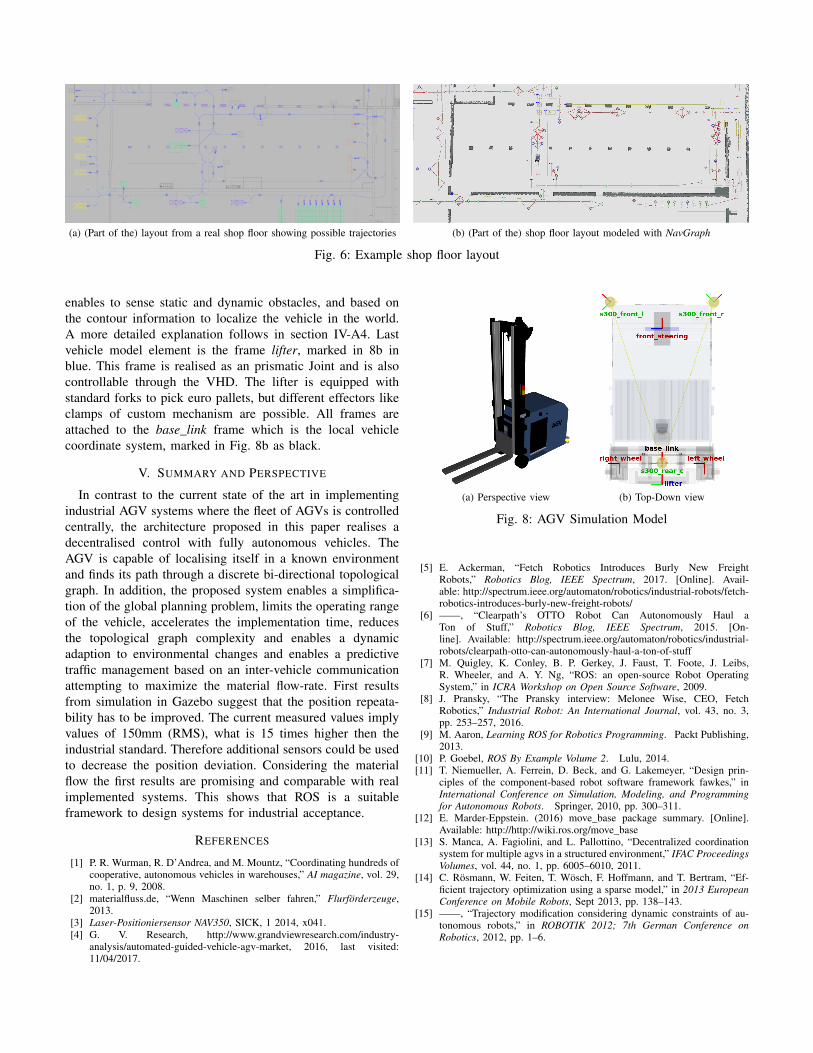
The simulation model is realised as a virtual model in thesimulation environment Gazebo that comes with ROS (seeFig. 8). Using the ODE physics engine, a realistic motiongeneration has been achieved. The AGV is based on a tricyclekinematic model, in Figure 8b marked in red. The framesright_wheel and left_wheel are passive and are used to cal-culate the vehicle odometry, while the frame front_steeringcan be actuated in linear x and angular z direction. A virtualhardware driver (VHD) is translating linear and angular ve-locity commands into corresponding joint rotational velocitiesto provide propulsion and steering. To simulate the dynamicbehaviour the steering speed can be limited. Additionally,three virtual 2D LIDAR sensors are implemented to provide aperception of the environment with an 360◦ field of view. This
(a) (Part of the) layout from a real shop floor showing possible trajectories (b) (Part of the) shop floor layout modeled with NavGraph
Fig. 6: Example shop floor layout
enables to sense static and dynamic obstacles, and based onthe contour information to localize the vehicle in the world.A more detailed explanation follows in section IV-A4. Lastvehicle model element is the frame lifter, marked in 8b inblue. This frame is realised as an prismatic Joint and is alsocontrollable through the VHD. The lifter is equipped withstandard forks to pick euro pallets, but different effectors likeclamps of custom mechanism are possible. All frames areattached to the base_link frame which is the local vehiclecoordinate system, marked in Fig. 8b as black.
V. SUMMARY AND PERSPECTIVE
In contrast to the current state of the art in implementingindustrial AGV systems where the fleet of AGVs is controlledcentrally, the architecture proposed in this paper realises adecentralised control with fully autonomous vehicles. TheAGV is capable of localising itself in a known environmentand finds its path through a discrete bi-directional topologicalgraph. In addition, the proposed system enables a simplifica-tion of the global planning problem, limits the operating rangeof the vehicle, accelerates the implementation time, reducesthe topological graph complexity and enables a dynamicadaption to environmental changes and enables a predictivetraffic management based on an inter-vehicle communicationattempting to maximize the material flow-rate. First resultsfrom simulation in Gazebo suggest that the position repeata-bility has to be improved. The current measured values implyvalues of 150mm (RMS), what is 15 times higher then theindustrial standard. Therefore additional sensors could be usedto decrease the position deviation. Considering the materialflow the first results are promising and comparable with realimplemented systems. This shows that ROS is a suitableframework to design systems for industrial acceptance.
REFERENCES
[1] P. R. Wurman, R. D’Andrea, and M. Mountz, “Coordinating hundreds ofcooperative, autonomous vehicles in warehouses,” AI magazine, vol. 29,no. 1, p. 9, 2008.
[2] materialfluss.de, “Wenn Maschinen selber fahren,” Flurförderzeuge,2013.
[3] Laser-Positioniersensor NAV350, SICK, 1 2014, x041.[4] G. V. Research, http://www.grandviewresearch.com/industry-
analysis/automated-guided-vehicle-agv-market, 2016, last visited:11/04/2017.
(a) Perspective view (b) Top-Down view
Fig. 8: AGV Simulation Model
[5] E. Ackerman, “Fetch Robotics Introduces Burly New FreightRobots,” Robotics Blog, IEEE Spectrum, 2017. [Online]. Avail-able: http://spectrum.ieee.org/automaton/robotics/industrial-robots/fetch-robotics-introduces-burly-new-freight-robots/
[6] ——, “Clearpath’s OTTO Robot Can Autonomously Haul aTon of Stuff,” Robotics Blog, IEEE Spectrum, 2015. [On-line]. Available: http://spectrum.ieee.org/automaton/robotics/industrial-robots/clearpath-otto-can-autonomously-haul-a-ton-of-stuff
[7] M. Quigley, K. Conley, B. P. Gerkey, J. Faust, T. Foote, J. Leibs,R. Wheeler, and A. Y. Ng, “ROS: an open-source Robot OperatingSystem,” in ICRA Workshop on Open Source Software, 2009.
[8] J. Pransky, “The Pransky interview: Melonee Wise, CEO, FetchRobotics,” Industrial Robot: An International Journal, vol. 43, no. 3,pp. 253–257, 2016.
[9] M. Aaron, Learning ROS for Robotics Programming. Packt Publishing,2013.
[10] P. Goebel, ROS By Example Volume 2. Lulu, 2014.[11] T. Niemueller, A. Ferrein, D. Beck, and G. Lakemeyer, “Design prin-
ciples of the component-based robot software framework fawkes,” inInternational Conference on Simulation, Modeling, and Programmingfor Autonomous Robots. Springer, 2010, pp. 300–311.
[12] E. Marder-Eppstein. (2016) move_base package summary. [Online].Available: http://http://wiki.ros.org/move_base
[13] S. Manca, A. Fagiolini, and L. Pallottino, “Decentralized coordinationsystem for multiple agvs in a structured environment,” IFAC ProceedingsVolumes, vol. 44, no. 1, pp. 6005–6010, 2011.
[14] C. Rösmann, W. Feiten, T. Wösch, F. Hoffmann, and T. Bertram, “Ef-ficient trajectory optimization using a sparse model,” in 2013 EuropeanConference on Mobile Robots, Sept 2013, pp. 138–143.
[15] ——, “Trajectory modification considering dynamic constraints of au-tonomous robots,” in ROBOTIK 2012; 7th German Conference onRobotics, 2012, pp. 1–6.