a course material on ee 2352 solid state drives - · pdf filea course material on ee 2352...
TRANSCRIPT
A Course Material on
EE 2352 Solid State Drives
By
Mr.N.Kannapiran
ASSISTANT PROFESSOR
DEPARTMENT OF ELECTRONICS AND COMMUNICATION ENGINEERING
SASURIE COLLEGE OF ENGINEERING
VIJAYAMANGALAM – 638 056

QUALITY CERTIFICATE
This is to certify that the e-course material
Subject Code : EE2352
Subject : Solid State Drives
Class : III Year EEE
being prepared by me and it meets the knowledge requirement of the university curriculum.
Signature of the Author
N.Kannapiran
ASSISTANT PROFESSOR
This is to certify that the course material being prepared by Mr.N.Kannapiran is of adequate
quality. He has referred more than five books among them minimum one is from abroad author.
Signature of HD
S. SRIRAM
ASSISTANT PROFESSOR
SNO
CONTENTS PAGENO
UNIT I DRIVE CHARACTERISTICS
1.1 Equations governing motor load dynamics 31.2 Classification of Load Torques 41.3 Multi quadrant Operation 81.4 Steady State Stability 10
UNIT II CONVERTER / CHOPPER FED DC MOTOR DRIVE2.1 Single Phase Fully Controlled Converter Fed Separately Excited D.C
Motor Drive16
2.2 Continuous Armature Current 172.3 DISCONTINUOUS ARMATURE CURRENT 202.4 Three Phase Fully Controlled Converter Fed Separately Excited D.C
Motor Drive22
2.5 Four Quadrant Operation of a Converters 242.6 Time Ratio Control 25
Current- Limit Control 26UNIT III DESIGN OF CONTROLLERS FOR DRIVES
3.1 Transfer Function For DC Motor 273.2 Armature current controlled 293.3 Closed Loop Control With Current And Speed Feedback 303.4 Speed control by armature voltage variation 343.5 Flux-Weakening Control Design and Analysis 353.6 Speed Controller 353.7 Current Controller 36
UNIT IV INDUCTION MOTOR DRIVES4.1 Stator Voltage Control 374.2 V/F Control 384.3 Field Weakening Mode 404.4 Voltage-source Inverter-driven Induction Motor 464.5 Vector Control of AC Induction Machines 524.6 Closed-loop control of induction motor 554.7 Constant air gap flux control 56
UNIT V SYNCHRONOUS MOTOR DRIVES5.1 V/F of Permanent Magnets Synchronous Motors 575.2 Self-Control Synchronous Motor 585.3 Power Factor Correction Of Permanent Magnet Synchronous Motor
Drive62
5.4 Design Equations Of Boost Power Factor Correction Circuit 655.5 Permanent Magnet Synchronous Motor Black Diagram Of Closed
Loop Control67
5.6 Vector Control Technique 69A Question Bank 70B University Question 88

EE2352 SOLID STATE DRIVES L T P C 3 0 0 3
AIMTo study and understand the operation of electric drives controlled from a power electronicconverter and to introduce the design concepts of controllers.
OBJECTIVES To understand the stable steady-state operation and transient dynamics of a motor-
load system. To study and analyze the operation of the converter / chopper fed dc drive and to solve
simple problems. To study and understand the operation of both classical and modern induction motor
drives. To understand the differences between synchronous motor drive and induction motor
drive and to learn the basics of permanent magnet synchronous motor drives. To analyze and design the current and speed controllers for a closed loop solid-state
DC motor drive and simulation using a software package
UNIT I DRIVE CHARACTERISTICS 9Equations governing motor load dynamics - steady state stability - Multi quadrant dynamics -Acceleration, deceleration, starting and stopping - load torque characteristics of various drives.
UNIT II CONVERTER / CHOPPER FED DC MOTOR DRIVE 9Steady state analysis of the single and three phase fully controlled converter fed separatelyexcited D.C motor drive - Continuous and discontinuous conduction Time ratio and currentlimit control - 4 quadrant operation of converter.
UNIT III DESIGN OF CONTROLLERS FOR DRIVES 9Transfer function for DC motor, load and converter – Closed loop control with current andspeed feedback - Armature voltage control and field weakening mode control, Design ofcontrollers: Current controller and speed controller - Converter selection and characteristics -Use of simulation software package.
UNIT IV INDUCTION MOTOR DRIVES 9Stator voltage control – energy efficient drive - v/f control, constant air-gap flux – fieldweakening mode - voltage/current fed inverters - Block diagram of vector control - closed loopcontrol.UNIT V SYNCHRONOUS MOTOR DRIVES 9V/f control and self-control of synchronous motor – Marginal angle control and power factorcontrol - Permanent magnet synchronous motor Black diagram of closed loop control.
TOTAL : 45 PERIODSTEXT BOOKS:1. Gopal K.Dubey, “Power Semi conductor controlled drives “ Prentice Hall Inc., New Jersey1989.2. Bimal K. Bose. ‘Modern Power Electronics and AC Drives’, PHI / Pearson Education, 2002.REFERENCES:1. N.K.De and S.K.Sen Electrical Drices” PHI, 2006 9th print.2. Murphy J.M.D. and Turnbull, “ Thyristor control of AC Motor” Pergamon Press Oxford 1988.

EE2352 SOLID STATE DRIVES
SCE 1 Dept. of EEE
UNIT-I
DRIVE CHARACTERISTICS
Electrical Drives:
Motion control is required in large number of industrial and domestic applications liketransportation systems, rolling mills, paper machines, textile mills, machine tools, fans, pumps, robots,washing machines etc.
Systems employed for motion control are called DRIVES, and may employ any of prime moverssuch as diesel or petrol engines, gas or steam turbines, steam engines, hydraulic motors and electricmotors, for supplying mechanical energy for motion control. Drives employing electric motors are knownas Electrical Drives.
An Electric Drive can be defined as an electromechanical device for converting electrical energyinto mechanical energy to impart motion to different machines and mechanisms for various kinds ofprocess control.
Classification of Electric Drives
According to Mode of Operation
Continuous duty drives Short time duty drives Intermittent duty drives
According to Means of Control
Manual Semi-automatic Automatic
According to Number of machines
Individual drive Group drive Multi-motor drive
According to Dynamics and Transients
Uncontrolled transient period Controlled transient period
According to Methods of Speed Control
Reversible and non-reversible uncontrolled constant speed. Reversible and non-reversible step speed control. Variable position control.
Reversible and non-reversible smooth speed control.

EE2352 SOLID STATE DRIVES
SCE 2 Dept. of EEE
Advantages of Electrical Drive
They have flexible control characteristics. The steady state and dynamic characteristics of electric drivescan be shaped to satisfy the load requirements.
1. Drives can be provided with automatic fault detection systems. Programmable logic controllerand computers can be employed to automatically control the drive operations in a desiredsequence.
2. They are available in wide range of torque, speed and power.3. They are adaptable to almost any operating conditions such as explosive and radioactive
environments4. It can operate in all the four quadrants of speed-torque plane5. They can be started instantly and can immediately be fully loaded6. Control gear requirement for speed control, starting and braking is usually simple and easy to
operate.
Choice (or) Selection of Electrical Drives
Choice of an electric drive depends on a number of factors. Some of the important factors are.
Steady State Operating conditions requirements:
Nature of speed torque characteristics, speed regulation, speed range, efficiency, duty cycle,quadrants of operation, speed fluctuations if any, ratings etc
Transient operation requirements:
Values of acceleration and deceleration, starting, braking and reversing performance.
Requirements related to the source:
Types of source and its capacity, magnitude of voltage, voltage fluctuations, power factor,harmonics and their effect on other loads, ability to accept regenerative power
Capital and running cost, maintenance needs life.
Space and weight restriction if any.
Environment and location.
Reliability.
Group Electric Drive
This drive consists of a single motor, which drives one or more line shafts supported onbearings. The line shaft may be fitted with either pulleys and belts or gears, by means of which a group ofmachines or mechanisms may be operated. It is also sometimes called as SHAFT DRIVES.
Advantages
A single large motor can be used instead of number of small motors
Disadvantages
There is no flexibility. If the single motor used develops fault, the whole process will be stopped.

EE2352 SOLID STATE DRIVES
SCE 3 Dept. of EEE
Individual Electric Drive
In this drive each individual machine is driven by a separate motor. This motor also impartsmotion to various parts of the machine.
Multi Motor Electric Drive
In this drive system, there are several drives, each of which serves to actuate one of the workingparts of the drive mechanisms.
E.g. Complicated metal cutting machine tools
Paper making industries, rolling machines etc.
Classification of Electrical Drives
Another main classification of electric drive is
DC drive AC drive
Applications
Paper mills
Cement Mills
Textile mills
Sugar Mills
Steel Mills
Electric Traction
Petrochemical Industries
Electrical Vehicles
1.1 Dynamics of Motor Load System
A motor generally drives a load (Machines) through some transmission system. While motoralways rotates, the load may rotate or undergo a translational motion.
Load speed may be different from that of motor, and if the load has many parts, their speed maybe different and while some parts rotate others may go through a translational motion.
Equivalent rotational system of motor and load is shown in the figure.

EE2352 SOLID STATE DRIVES
SCE 4 Dept. of EEE
J = Moment of inertia of motor load system referred to the motor shaft kg / m2
ωm = Instantaneous angular velocity of motor shaft, rad/sec.
T = Instantaneous value of developed motor torque, N-m
Tl = Instantaneous value of load torque, referred to the motor shaft N-m
Load torque includes friction and wind age torque of motor. Motor-load system shown infigure can be described by the following fundamental torque equation.
Equation (1) is applicable to variable inertia drives such as mine winders, reel drives, Industrial robots.
For drives with constant inertia
Equation (2) shows that torque developed by motor
1.2 Classification of Load Torques:
Various load torques can be classified into broad categories.
Active load torques Passive load torques
Load torques which has the potential to drive the motor under equilibrium conditions are calledactive load torques. Such load torques usually retain their sign when the drive rotation is changed(reversed)
Eg:
Torque due to force of gravity Torque due tension Torque due to compression and torsion etc
Load torques which always oppose the motion and change their sign on the reversal of motion arecalled passive load torques
Eg:
Torque due to friction, cutting etc.
Components of Load Torques:
The load torque Tl can be further divided in to following components

EE2352 SOLID STATE DRIVES
SCE 5 Dept. of EEE
Friction Torque (TF):
Friction will be present at the motor shaft and also in various parts of the load. TF is the equivalentvalue of various friction torques referred to the motor shaft.
Windage Torque (TW)
When motor runs, wind generates a torque opposing the motion. This is known as windage torque.
Torque required to do useful mechanical work
Nature of this torque depends upon particular application. It may be constant and independent of speed.It may be some function of speed, it may be time invariant or time variant, its nature may also changewith the load’s mode of operation.
Friction at zero speed is called diction or static friction. In order to start the drive the motor should atleast exceeds diction.
Friction torque can also be resolved into three components
Component Tv varies linearly with speed is called VISCOUS friction and is given by
Tv = B ωm
Where B is viscous friction co-efficient.
Another component TC, which is independent of speed, is known as COULOMB friction.Third component Ts accounts for additional torque present at stand still. Since Ts is present only at standstill it is not taken into account in the dynamic analysis. Wind age torque, TW which is proportional tospeed Squared is given by

EE2352 SOLID STATE DRIVES
SCE 6 Dept. of EEE
From the above discussions, for finite speed
Characteristics of Different types of Loads
One of the essential requirements in the section of a particular type of motor for driving a machineis the matching of speed-torque characteristics of the given drive unit and that of the motor. Thereforethe knowledge of how the load torque varies with speed of the driven machine is necessary. Different typesof loads exhibit different speed torque characteristics. However, most of the industrial loads can beclassified into the following four categories.
Constant torque type load
Torque proportional to speed (Generator Type load) Torque proportional to square of the speed (Fan type load) Torque inversely proportional to speed (Constant power type load)
Constant Torque characteristics:
Most of the working machines that have mechanical nature of work like shaping, cutting, grindingor shearing, require cons tant torque irrespective of speed. Similarly cranes during the hoisting andconveyors handling constant weight of material per unit time also exhibit this type of Characteristics
Torque Proportional to speed:
Separately excited dc generators connected to a constant resistance load, eddy current brakes have speedtorque characteristics given by
T=k
Torque proportional to square of the speed:
Another type of load met in practice is the one in which load torque is proportional to thesquare of the speed.

EE2352 SOLID STATE DRIVES
SCE 7 Dept. of EEE
Examples:
Fans rotary pumps, Compressors Ship propellers
Torque Inversely proportional to speed:
Certain types of lathes, boring machines, milling machines, steel mill coiler and electrictraction load exhibit hyperbolic speed-torque characteristics

EE2352 SOLID STATE DRIVES
SCE 8 Dept. of EEE
1.3 Multi quadrant Operation:
For consideration of multi quadrant operation of drives, it is useful to establish suitableconventions about the signs of torque and speed.
A motor operates in two modes – Motoring and braking. In motoring, it converts electrical energyinto mechanical energy, which supports its motion .In braking it works as a generator convertingmechanical energy into electrical energy and thus opposes the motion.
Now consider equilibrium point B which is obtained when the same motor drives another load asshown in the figure. A decrease in speed causes the load torque to become greater than the motor torque,electric drive decelerates and operating point moves away from point B.
Similarly when working at point B and increase in speed will make motor torque greater than theload torque, which will move the operating point away from point B
Similarly operation in quadrant III and IV can be identified as reverse motoring and reversebraking since speed in these quadrants is negative.
For better understanding of the above notations, let us consider operation of hoist in fourquadrants as shown in the figure. Direction of motor and load torques and direction of speed are markedby arrows
The figure at the right represents a DC motor attached to an inertial load. Motor can provide motoringand braking operations for both forward and reverse directions.
Figure shows the torque and speed co-ordinates for both forward and reverse motions. Power developedby a motor is given by the product of speed and torque. For motoring operations Power developed ispositive and for braking operations power developed is negative.
For better understanding of the above notations, let us consider operation of hoist in fourquadrants as shown in the figure. Direction of motor and load torques and direction of speed are markedby arrows.

EE2352 SOLID STATE DRIVES
SCE 9 Dept. of EEE
A hoist consists of a rope wound on a drum coupled to the motor shaft one end of the rope is tiedto a cage which is used to transport man or material from one level to another level . Other end of the ropehas a counter weight. Weight of the counter weight is chosen to be higher than the weight of empty cagebut lower than of a fully loaded cage.
Forward direction of motor speed will be one which gives upward motion of the cage. Load torqueline in quadrants I and IV represents speed-torque characteristics of the loaded hoist. This torque is thedifference of torques due to loaded hoist and counter weight. The load torque in quadrants II and III isthe speed torque characteristics for an empty hoist.

EE2352 SOLID STATE DRIVES
SCE 10 Dept. of EEE
This torque is the difference of torques due to counter weight and the empty hoist. Its sigh isnegative because the counter weight is always higher than that of an empty cage. The quadrant I operationof a hoist requires movement of cage upward, which corresponds to the positive motor speed which is incounter clockwise direction here. This motion will be obtained if the motor products positive torque inCCW direction equal to the magnitude of load torque TL1.
Since developed power is positive, this is forward motoring operation. Quadrant IV is obtainedwhen a loaded cage is lowered. Since the weight of the loaded cage is higher than that of the counter weight.It is able to overcome due to gravity itself.
In order to limit the cage within a safe value, motor must produce a positive torque T equal to TL2in anticlockwise direction. As both power and speed are negative, drive is operating in reverse brakingoperation. Operation in quadrant II is obtained when an empty cage is moved up. Since a counter weighis heavier than an empty cage, its able to pull it up.
In order to limit the speed within a safe value, motor must produce a braking torque equal to TL2in clockwise direction. Since speed is positive and developed power is negative, it’s forward brakingoperation.
Operation in quadrant III is obtained when an empty cage is lowered. Since an empty cage has alesser weight than a counter weight, the motor should produce a torque in CW direction. Since speed isnegative and developed power is positive, this is reverse motoring operation. During transient condition,electrical motor can be assumed to be in electrical equilibrium implying that steady state speed torquecurves are also applicable to the transient state operation.
1.4 Steady State Stability:
Equilibrium speed of motor-load system can be obtained when motor torque equals the load torque.Electric drive system will operate in steady state at this speed, provided it is the speed of stable stateequilibrium.
Concept of steady state stability has been developed to readily evaluate the stability of anequilibrium point from the steady state speed torque curves of the motor and load system. In most of theelectrical drives, the electrical time constant of the motor is negligible compared with the mechanical timeconstant. During transient condition, electrical motor can be assumed to be in electrical equilibriumimplying that steady state speed torque curves are also applicable to the transient state operation.
Now, consider the steady state equilibrium point A shown in figure below

EE2352 SOLID STATE DRIVES
SCE 11 Dept. of EEE
Now consider equilibrium point B which is obtained when the same motor drives another load asshown in the figure.
A decrease in speed causes the load torque to become greater than the motor torque, electric drivedecelerates and operating point moves away from point B.
Similarly when working at point B and increase in speed will make motor torque greater than theload torque, which will move the operating point away from point B
Basics of Regenerative Braking
In the regenerative braking operation, the motor operates as generator, while it is stillconnected to the supply. Here, the motor speed is greater than the synchronous speed.
Mechanical energy is converted into electrical energy, part of which is returned to the supply andrest of the energy is last as heat in the winding and bearings of electrical machines pass smoothly frommotoring region to generating region, when over driven by the load.
An example of regenerative braking is shown in the figure below. Here an electric motor is drivinga trolley bus in the uphill and downhill direction. The gravity force can be resolved into two componentsin the uphill direction.
One is perpendicular to the load surface (F) and another one is parallel to the road surface Fl. Theparallel force pulls the motor towards bottom of the hill.
If we neglect the rotational losses, the motor must produce force Fm opposite to Fl to move thebus in the uphill direction.
Here the motor is still in the same direction on both sides of the hill. This is known as regenerativebraking. The energy is exchange under regenerative braking operation is power flows from mechanicalload to source.

EE2352 SOLID STATE DRIVES
SCE 12 Dept. of EEE
This operation is indicated as shown in the figure below in the first quadrant. Here the powerflow is from the motor to load.
Now we consider that the same bus is traveling in down hill, the gravitational force doesn’t changeits direction but the load torque pushes the motor towards the bottom of the hill. The motor produces atorque in the reverse direction because the direction of the motor torque is always opposite to the directionof the load torque.
Here the motor is still in the same direction on both sides of the hill. This is known as regenerativebraking. The energy is exchange under regenerative braking operation is power flows from mechanicalload to source. Hence, the load is driving the machine and the machine is generating electric power thatis returned to the supply.

EE2352 SOLID STATE DRIVES
SCE 13 Dept. of EEE
Regenerative braking of Induction motor:
An induction motor is subjected to regenerative braking, if the motor rotates in the same directionas that of the stator magnetic field, but with a speed greater than the synchronous speed. Such a state occursduring any one of the following process.
Downward motion of a loaded hoisting mechanism During flux weakening mode of operation of IM.
Under regenerative braking mode, the machine acts as an induction generator. The induction generatorgenerates electric power and this power is fed back to the supply. This machine takes only the reactivepower for excitation.
The speed torque characteristic of the motor for regenerative braking is shown in the figure.
Regenerative Braking for DC motor:
In regenerative braking of dc motor, generated energy is supplied to the source. For this thefollowing condition is to be satisfied.
E > V and Ia should be negative

EE2352 SOLID STATE DRIVES
SCE 14 Dept. of EEE
Modes of Operation:
An electrical drive operates in three modes
Steady state Acceleration including Starting Deceleration including Stopping
We know that
T=T1 +J d/dt (ωm)
According to the above expression the steady state operation takes place when motor torque equalsthe load torque. The steady state operation for a given speed is realized by adjustment of steady state motorspeed torque curve such that the motor and load torques are equal at this speed. Change in speed is achievedby varying the steady state motor speed torque curve so that motor torque equals the load torque at thenew desired speed. In the figure shown below when the motor parameters are adjusted to provide speedtorque curve 1, drive runs at the desired speedωm 1 .
Speed is changed to ωm 2 when the motor parameters are adjusted to provide speed torque curve2. When load torque opposes motion, the motor works as a motor operating in quadrant I or IIIdepending on the direction of rotation. When the load is active it can reverse its sign and act to assistthe motion. Steady state operation for such a case can be obtained by adding a mechanical brake whichwill produce a torque in a direction to oppose the motion. The steady state operation is obtained at aspeed for which braking torque equal the load torque. Drive operates in quadrant II or IV depending uponthe rotation.
Acceleration and Deceleration modes are transient modes. Drive operates in acceleration modewhenever an increase in its speed is required. For this motor speed torque curve must be changed so thatmotor torque exceeds the load torque. Time taken for a given change in speed depends on inertia of motorload system and the amount by which motor torque exceeds the load torque.
Increase in motor torque is accompanied by an increase in motor current. Care must be taken torestrict the motor current with in a value which is safe for both motor and power modulator. In applicationsinvolving acceleration periods of long duration, current must not be allowed to exceed the rated value.When acceleration periods are of short duration a current higher than the rated value is allowed duringacceleration.

EE2352 SOLID STATE DRIVES
SCE 15 Dept. of EEE
In closed loop drives requiring fast response, motor current may be intentionally forced to themaximum value in order to achieve high acceleration. Figure shown below shows the transition fromoperating point A at speed.
Point B at a higher speedωm 2, when the motor torque is held constant during acceleration. Thepath consists of AD1E1B. In the figure below, 1 to 5 are motor speed torque curves. Starting is a specialcase of acceleration where a speed change from 0 to a desired speed takes place. All points mentioned inrelation to acceleration are applicable to starting.
The maximum current allowed should not only be safe for motor and power modulator but drop insource voltage caused due to it should also be in acceptable limits. In some applications the motor shouldaccelerate smoothly, without any jerk. This is achieved when the starting torque can be increased steplessly from its zero value. Such a start is known as soft start.

EE2352 SOLID STATE DRIVES
SCE 16 Dept. of EEE
UNIT II
CONVERTER / CHOPPER FED DC MOTOR DRIVE
2.1 Single Phase Fully Controlled Converter Fed Separately Excited D.C Motor Drive
Fig 2.1
The basic circuit for a single-phase separately excited dc motor drive is shown in Fig. 2.1.Thearmature voltage is controlled by a semi-converter or full-converter and the field circuit is fed from theac supply through a diode bridge. The motor current cannot reverse due to the thyristors in the converters.If semi-converters are used, the average output voltage (Ea)is always positive. Therefore power flow(Ea1a) is always positive, that is, from the ac supply to the dc load. In drive system semi-converters,regeneration or reverse power flow from motor to ac supply is not possible. In semi-converters free-wheel (i.e., dissipation of armature inductance energy through the free-wheeling path) takes place whenthe thyristor blocks.
Single-phase full-wave drives are used for low and medium-horsepower applications asindicated infig2.1.Suchdriveshavepoor speed regulation on open-loop firing angle control. However, witharmature voltage or tachometer feedback, good regulation can be achieved.
Basic Equation I
The armature circuit of the de motor is represented by its back voltage eg, armature resistance Ra, andarmature inductance LaasshowninFig.2.1.
Back voltage:
(1)

EE2352 SOLID STATE DRIVES
SCE 17 Dept. of EEE
Average Back Voltage
(2)
Developed torque:
(3)
Average developed torque:
(4)
The armature circuit voltage equation is
(5)
Interms of average values,
(6)
Note that the inductance La does not absorb any average voltage. From equations 2 and 6, theaverage speed is
In single-phase converters, the armature voltage ea and current t, change with time. This is unlikethe M-G set drive in which both ea and t, are essentially constant. In phase-controlled converters, thearmature current ia may not even be continuous. In fact, for most operating conditions, t, is discontinuous.This makes prediction of performance difficult. Analysis is simplified if continuity of armature current canbe assumed. Analysis for both continuous and discontinuous current is presented in the following sections
2.2 Continuous Armature Current
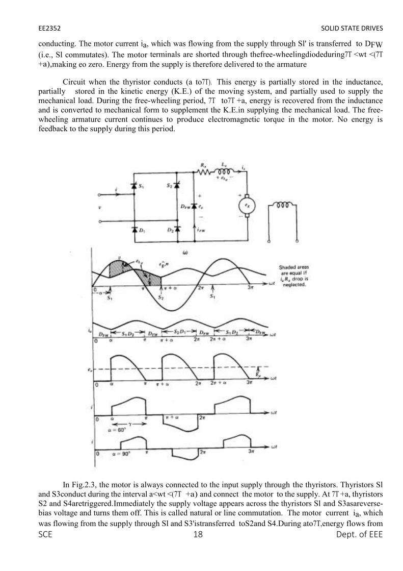
Let us assume that the armature current is continuous over the whole range of operation. Typicalvoltage and current waveforms are shown in Figs.2.2 and 2.3 for semi-converter and full-convertersystems, respectively. The thyristors are symmetrically triggered. In the semi-convertersystemshowninFig.2.2, thyristor Sl is triggered at an angle a and S2atan anglea+7T with respect to thesupply voltage v. In the full-converter systemshowninFig.2.3, thyristors S,and S3 are simultaneouslytriggered at a, thyristors S2andS4aretriggeredat7T +a.
In Fig. 2.2, the motor is connected to the input supply for the period a<wt<7T through Sl and D2,and the motor terminal voltage ea is the same as the supply input voltage v. Beyond 7T, ea tends to reverseas the input voltage changes polarity. This will forward-bias the free-wheeling diode and DFW will start
EE2352 SOLID STATE DRIVES
SCE 18 Dept. of EEE
conducting. The motor current ia, which was flowing from the supply through Sl' is transferred to DFW(i.e., Sl commutates). The motor terminals are shorted through thefree-wheelingdiodeduring7T <wt <(7T+a),making eo zero. Energy from the supply is therefore delivered to the armature
Circuit when the thyristor conducts (a to7T). This energy is partially stored in the inductance,partially stored in the kinetic energy (K.E.) of the moving system, and partially used to supply themechanical load. During the free-wheeling period, 7T to7T +a, energy is recovered from the inductanceand is converted to mechanical form to supplement the K.E.in supplying the mechanical load. The free-wheeling armature current continues to produce electromagnetic torque in the motor. No energy isfeedback to the supply during this period.
In Fig.2.3, the motor is always connected to the input supply through the thyristors. Thyristors Sland S3conduct during the interval a<wt <(7T +a) and connect the motor to the supply. At 7T +a, thyristorsS2 and S4aretriggered.Immediately the supply voltage appears across the thyristors Sl and S3asareverse-bias voltage and turns them off. This is called natural or line commutation. The motor current ia, whichwas flowing from the supply through Sl and S3'istransferred toS2and S4.During ato7T,energy flows from

EE2352 SOLID STATE DRIVES
SCE 19 Dept. of EEE
the input supply to the motor (both v and ia repositive, and eo and io are positive, signifying positive powerflow). However, during 7T to 7T +a, some of the motor system energy is feedback to the input supply(vand I have opposite polarities and likewise ea and io' signifying reverse power flow).
In Fig.2.3c voltage and current waveforms are shown for a firing angle greater than 90°.The averagemotor terminal voltage Eo is negative. If the motor back emf Eg is reversed, it will behave as a de-generator and will feed power back to the ac supply. This is known as the inversion operation of theconverter, and this mode of operation is used in the regenerative braking of the motor.
Torque Speed Characteristics
For a semi-converter with free-wheeling action the armature circuit equations are:
Single-Phase Separately Excited DC Motor Drives
The armature circuit equation for a full-converter is:

EE2352 SOLID STATE DRIVES
SCE 20 Dept. of EEE
2.3 DISCONTINUOUS ARMATURE CURRENT
The torque-speed characteristics shown in Fig.2.4bare drawn on the crude assumption that thearmature current is continuous over the whole range of operation. It is very doubtful that the armaturecurrent will be continuous at high values of the firing angle a, high speed, and low values of torque. In fact,armature current is discontinuous for these operating conditions. If the armature current is discontinuous,the no-load speeds will be higher than those shown in Fig.2.4b, and the speed regulation will besignificantly poor in the region of discontinuous armature current. The motor performance

EE2352 SOLID STATE DRIVES
SCE 21 Dept. of EEE
. IThe waveforms with semi-converter and full-converter with discontinuous armature current
areshowninFig.2.5andFig.2.6, respectively.
In Fig. 2.5, the motor is connected to the input supply for the period a<wI <71' through S, andDz.Beyond 71', the motor terminal is shorted through the free-wheeling diode DFW' The armature currentdecays to zero at before the thyristor S2 is triggered at71' +a, thereby making the armature currentdiscontinuous. During a to 71' (i.e., the conduction period of the thyristor S,), motor terminal voltage ea isthe same as the supply voltage v. However, during the motor current free-wheels through DFW and soea s zero. The motor coasts and the motor terminal voltage ea is the same as the back voltage InFig.2.6, the

EE2352 SOLID STATE DRIVES
SCE 22 Dept. of EEE
motor is connected to the supply during a<wt<{3 and it Coasts during {3<wI <71' +a. As long as the motoris connected to the supply, its terminal voltage is the same as the input supply voltage.
If the armature current can be assumed to be continuous, the torque-speed characteristics can becalculated merely from average values ofthe motor terminal voltage and current. In the discontinuouscurrent mode, these calculations are cumbersome. The difficulty arises in the calculation of the averagemotor terminal voltage Ea, because (called the extinction angle, the instant at which the thyristor or motorcurrent becomes zero) depends on, the average speed N, average armature current la' and the firing anglea. A general approach, valid for both continuous and discontinuous armature current, is thereforen e c e s s a r y .
2.4 Three Phase Fully Controlled Converter Fed Separately Excited D.C Motor Drive
Three phase controlled rectifiers are used in large power DC motor drives. Three phase controlledrectifier gives more number of voltage per cycle of supply frequency. This makes motor current continuousand filter requirement also less.
The number of voltage pulses per cycle depends upon the number of thyristors and theirconnections for three phase controlled rectifiers. In three phase drives, the armature circuit is connectedto the output of a three phase controlled rectifier.
Three phase drives are used for high power applications up to megawatts power level. The ripplefrequency of armature voltage is greater than that of the single phase drives and its requires lessinductance in the armature circuit to reduce the armature current ripple
Three phase full converter are used in industrial application up to 1500KW drives. It is a twoquadrant converter.
Principle of Operation
Three phase full converter bridge circuit connected across the armature terminals is shown fig. Thevoltage and current waveforms of the converter. The circuit works as a three AC to DC converter for firingangle delay 00 < α < 900 and as a line commutated inverter for 900 < α < 1800 . A three full converter fedDC motor is performed where generation of power is required.

EE2352 SOLID STATE DRIVES
SCE 23 Dept. of EEE

EE2352 SOLID STATE DRIVES
SCE 24 Dept. of EEE
2.5 Four Quadrant Operation of a Converters
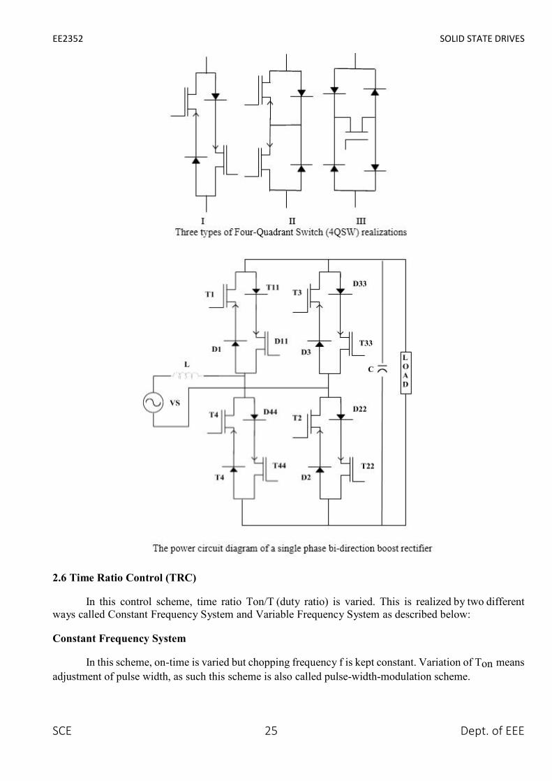
The bi-directional boost converter is the IPQC version of the conventional thyristor dual converters.Their topology is derived from ac-ac matrix converters using four quadrant switches (4QSWs). Since nofour-quadrant switch is currently commercially available the realized by embedding a transistor inside adiode bridge or by inverse parallel connections of transistors as shown in Fig (1). Power IGBT employedbecause they have the advantage so high switching frequency and small pulse and notch widths. Topologyof a single-phase bi-directional boost converter using typeI 4QSWsis shown in Fig(2).
In the circuit shown in Fig (2), here are four4QSWs, two in each limb. Each 4QSW comprises two2QSWs (two quadrant switches), each two-quadrant switch consisting of a IGBTT with series diode,connected in inverse-parallel. The operation of the bi-directional boost converter in boost mode and in aparticular quadrant in the V-I plane shown in Fig (3) is determined by the conditioning of the switchingstates of two sets (IandII) of devices. In the single-phase version each set comprises four IGBTs; set(A)IGBTs–T11,T22,T33,T44 and set(B)I GBTTs-T1,T2,T3,T4.corresponding to the four quadrants in thebuck and boost modes pertaining to the rectification and inversion operations
EE2352 SOLID STATE DRIVES
SCE 25 Dept. of EEE
2.6 Time Ratio Control (TRC)
In this control scheme, time ratio Ton/T (duty ratio) is varied. This is realized by two differentways called Constant Frequency System and Variable Frequency System as described below:
Constant Frequency System
In this scheme, on-time is varied but chopping frequency f is kept constant. Variation of Ton meansadjustment of pulse width, as such this scheme is also called pulse-width-modulation scheme.

EE2352 SOLID STATE DRIVES
SCE 26 Dept. of EEE
Variable Frequency System
In this technique, the chopping frequency f is varied and either (i) on-time Ton is kept constant or(ii) off-time Toff is kept constant. This method of controlling duty ratio is also called Frequency-modulation scheme.
2.7 Current- Limit Control
In this control strategy, the on and off of chopper circuit is decided by the previous set valueof load current. The two set values are maximum load current and minimum load current.
When the load current reaches the upper limit, chopper is switched off. When the load currentfalls below lower limit, the chopper is switched on. Switching frequency of chopper can be controlled bysetting maximum and minimum level of current.
Current limit control involves feedback loop, the trigger circuit for the chopper is therefore morecomplex. PWM technique is the commonly chosen control strategy for the power control in chopper circuit

EE2352 SOLID STATE DRIVES
SCE 27 Dept. of EEE
UNIT III
DESIGN OF CONTROLLERS FOR DRIVES
3.1Transfer Function For DC Motor

EE2352 SOLID STATE DRIVES
SCE 28 Dept. of EEE

EE2352 SOLID STATE DRIVES
SCE 29 Dept. of EEE

EE2352 SOLID STATE DRIVES
SCE 30 Dept. of EEE
3.3 Closed Loop Control With Current And Speed Feedback
Closed loop control improves on the drives performance by increasing speed of response andimproving on speed regulation. So the functions of closed loop control is that ωn is increased, ε is reduced,ts is reduced, and Speed Regulation (SR) is reduced. A closed loop speed control scheme is shown below
Schematic Diagram of the Closed Loop Speed Control

EE2352 SOLID STATE DRIVES
SCE 31 Dept. of EEE
Where, KfѠ is the tachometer feedback gain
Kc(s) is the speed controller gain
Kr(s) is the armature voltage regulator gain
The block diagram representation of the control configuration is shown below.
Block Diagram of the Closed Loop Speed Control.
If the tachometer loop does not contain a filter, the feedback gain can be a constant designated as Kfw
Kcw(s) = Kcwp + KcwI/ s +sKcwd
Where,
Kcwd is the proportional gain component of Kcw(s)
Kcwp is the integral gain component of Kcw(s) & Kcwd
Three possible controller configurations are possible:
1.For KcwI & Kcwd zero Kcw(S) = KcwpWhich is a Proportional Controller
2. For Kcwp & Kcwd zero Kcw(S) = KcwI/S Which is an Integral Controller

EE2352 SOLID STATE DRIVES
SCE 32 Dept. of EEE
3. For Kcwd zero Kcw(S) = Kcwp+ KcwI/S Which is a Proportional Integral Controller
Now taking the Proportional Controller as a case study, with Kcw(S) = Kcwp , the dynamic equation is,
Last Equation is a second order system
The Natural Frequency of Oscillation, ωn is,
This is always higher than the open loop case due to the factor Kф ,KfѠ, KcѠp
The Damping Ratio, ε , is
This is lower than in the open loop case due to the increase in ωn
Speed Regulation (SR) is also derived as

EE2352 SOLID STATE DRIVES
SCE 33 Dept. of EEE
,
SR is also lower than in the open loop case due to the factor Kф ,KfѠ, KcѠp . This is an indicationof a better drive performance.
Inner Current Loop Control
Improvement in speed control can be obtained with Inner Current Loop Control method, wherebyarmature current is fed back to the input. A closed loop speed control scheme with inner current control isshown in Figure.
Designating K1ci+Kr=Kci the block diagram representation of the control configuration is shown in Figure.
The dynamic equation is,
Schematic Diagram of the Inner Current Loop Control.

EE2352 SOLID STATE DRIVES
SCE 34 Dept. of EEE
Block Diagram of the Inner Current Loop Control
3.4 Speed control by armature voltage variation
In this method of speed control, armature is supplied from a separate variable Ac voltage source,while the field is separately excited with fixed rate dc voltage as shown in figure. Here the armatureresistance and field current are not varied. Since the no load speed the speed versus Ia characteristic willshift parallel as shown in figure for different values of Va.
As flux remains constant, this method is suitable for constant torque loads. In a way armaturevoltage control method dissimilar to that of armature resistance control method except that the former

EE2352 SOLID STATE DRIVES
SCE 35 Dept. of EEE
one is much superior as next repower loss takes place in the armature circuit. Armature voltage controlmethod is adopted for controlling speed from base speed down to very small speed, as one should notapply across the armature a voltage, which is higher than the rated voltage.
3.5 Flux-Weakening Control Design and Analysis
In order to produce the maximum torque, which main component is proportional to q-axis componentof the armature current, it is convenient to control the inverter-fed PMSM by keeping the direct, d-axis, currentcomponent to be id as long as the inverter output voltage doesn’t reach its limit.
At that point, the motor reaches its maximum speed, so-called rated speed (called al so base speed whentalking about flux-weakening). Beyond that limit, the motor torque decreases rapidly toward its minimum value,which depends on a load torque profile. To expand the speed above the rated value, the motor torque is necessaryto be reduced. A common method in the control of synchronous motors is to reduce the magnetizing current,which produces the magnetizing flux. This method is known as field-weakening. With PM synchronous motorsit is not possible, but, instead, the air gap flux is weakened by producing anegative d-axis current component,id.
Because nothing has happened to the excitation magnetic field and the air gap flux is still reduced, so isthe motor torque, this control method is called flux-weakening. As a basis for this analysis, the PMSM currentand voltage d-q vector diagrams from the previous section Fig are used. During flux-weakening, because thedemagnetizing (negative) id current increases, a phase current vector is rotates toward the negative d-semi-axis.The rotation of the phase voltage vector is determined by a chosen flux weakening strategy, but at the end offlux-weakening it always rotates toward the positive q- semi axis because of iq current, i.e vd voltage magnitudedecrease.
Hence, the voltage-to-current phase shift decreases to zero and increases in negative direction either tothe inverter phase shift limit (usually 300), or a load torque dictated steady-state (zero acceleration), or to thezero motor torque condition (no load or generative load). A big concern of flux-weakening control is a dangerof permanent demagnetization of magnets. However, large materials such as Samarium-Cobalt, allowssignificant id current which can extend the motor rated speed up to two times. Three commonly used flux-weakening control strategies are:
1) constant-voltage-constant-power(CVCP)control;
2) constant-current-constant-power(CCCP)control;and
3) optimum-current-vector(OCVorCCCV-constant-current-constant-voltage)control.
3.6 Speed Controller
The speed regulator in the following figure uses a PI controller. The controller outputs the armaturecurrent reference (in pu) used by the current controller in order to obtain the electromagnetic torque neededto reach the desired speed. During torque regulation, the speed controller is disabled.
The controller takes the speed reference (in rpm) and the rotor speed of the DC machine as inputs.The speed reference change rate will follow user-defined acceleration and deceleration ramps in order toavoid sudden reference changes that could cause armature over-current and destabilize the system. Thespeed measurement is filtered by a first-order low-pass filter.
EE2352 SOLID STATE DRIVES
SCE 36 Dept. of EEE
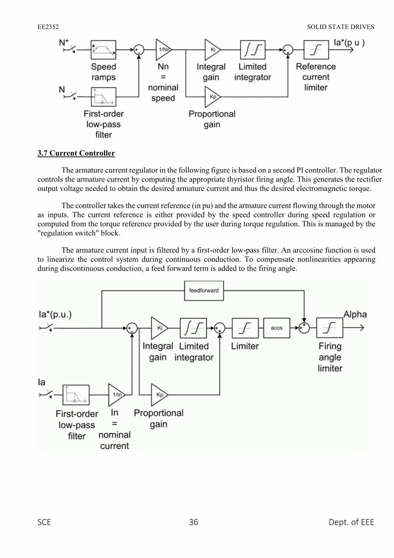
3.7 Current Controller
The armature current regulator in the following figure is based on a second PI controller. The regulatorcontrols the armature current by computing the appropriate thyristor firing angle. This generates the rectifieroutput voltage needed to obtain the desired armature current and thus the desired electromagnetic torque.
The controller takes the current reference (in pu) and the armature current flowing through the motoras inputs. The current reference is either provided by the speed controller during speed regulation orcomputed from the torque reference provided by the user during torque regulation. This is managed by the"regulation switch" block.
The armature current input is filtered by a first-order low-pass filter. An arccosine function is usedto linearize the control system during continuous conduction. To compensate nonlinearities appearingduring discontinuous conduction, a feed forward term is added to the firing angle.

EE2352 SOLID STATE DRIVES
SCE 37 Dept. of EEE
UNIT IV
INDUCTION MOTOR DRIVES
4.1 Stator Voltage Control
In this method of control, back-to-back thyristors are used to supply the motor with variable acvoltage. The analysis implies that the developed torque varies inversely as the square of the input RMSvoltage to the motor. This makes such a drive suitable for fan- and impeller-type loads for which torquedemand rises faster with speed. For other types of loads, the suitable speed range is very limited. Motorswith high rotor resistance may offer an extended speed range. It should be noted that this type of drive withback-to-back thyristors with firing-angle control suffers from poor power and harmonic distortion factorswhen operated at low speed. If unbalanced operation is acceptable, the thyristors in one or two supply linesto the motor may be bypassed. This offers the possibility of dynamic braking or plugging, desirable in someapplications.
FIGURE (a) Stator voltage controller. (b) Motor and load torque–speed characteristics under voltagecontrol.
The induction motor speed variation can be easily achieved for a short range by either stator voltagecontrol or rotor resistance control. But both of these schemes result in very low efficiencies at lower speeds.The most efficient scheme for speed control of induction motor is by varying supply frequency. This notonly results in scheme with wide speed range but also improves the starting performance. If the machineis operating at speed below base speed, then v/f ratio is to be kept constant so that flux remains constant.This retains the torque capability of the machine at the same value. But at lower frequencies, the torquecapability decrease and this drop in torque has to be compensated for increasing the applied voltage.

EE2352 SOLID STATE DRIVES
SCE 38 Dept. of EEE
4.2 V/F Control
Open Loop V/F Control
The open loop V/F control of an induction motor is the most common method of speed controlbecause of its simplicity and these types of motors are widely used in industry. Traditionally, inductionmotors have been used with open loop 50Hz power supplies for constant speed applications. Foradjustable speed drive applications, frequency control is natural. However, voltage is required to beproportional to frequency so that the stator flux
Ѱs=Ѵs/Ѡs
Remains constant if the stator resistance is neglected. The power circuit consists of a diode rectifierwith a single or three-phase ac supply, filter and PWM voltage-fed inverter. Ideally no feedback signalsare required for this control scheme.
The PWM converter is merged with the inverter block. Some problems encountered in the operationof this open loop drive are the following:
The speed of the motor cannot be controlled precisely, because the rotor speed will be slightlyless than the synchronous speed and that in this scheme the stator frequency and hence the synchronousspeed is the only control variable.
The slip speed, being the difference between the synchronous speed and the electrical rotor speed,cannot be maintained, as the rotor speed is not measured in this scheme. This can lead to operation in theunstable region of the torque-speed characteristics.
The effect of the above can make the stator currents exceed the rated current by a large amountthus endangering the inverter- converter combination
EE2352 SOLID STATE DRIVES
SCE 39 Dept. of EEE
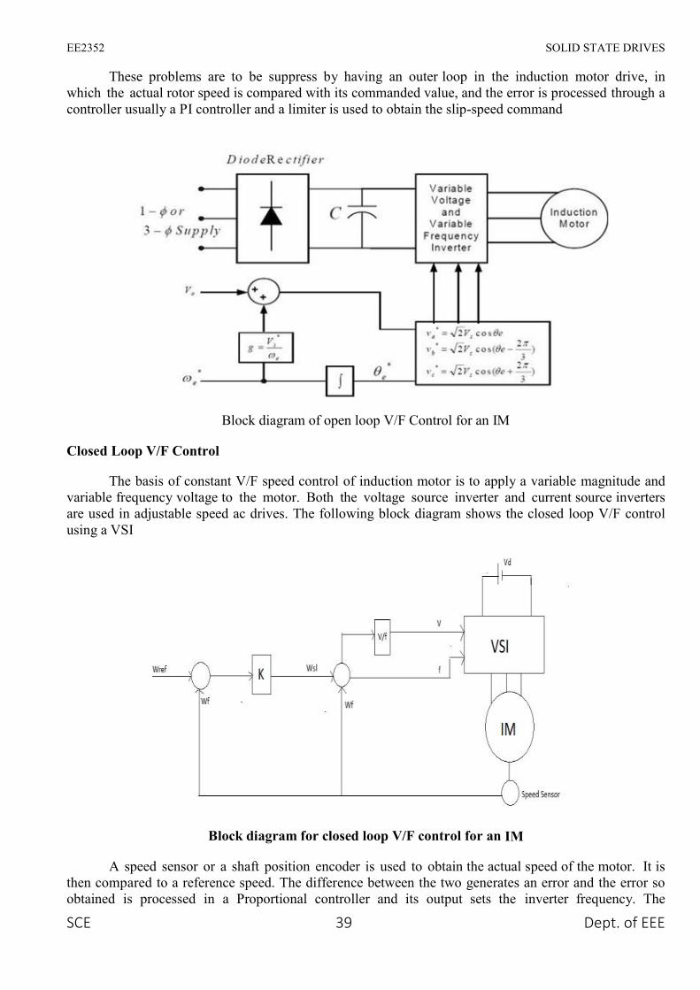
These problems are to be suppress by having an outer loop in the induction motor drive, inwhich the actual rotor speed is compared with its commanded value, and the error is processed through acontroller usually a PI controller and a limiter is used to obtain the slip-speed command
Block diagram of open loop V/F Control for an IM
Closed Loop V/F Control
The basis of constant V/F speed control of induction motor is to apply a variable magnitude andvariable frequency voltage to the motor. Both the voltage source inverter and current source invertersare used in adjustable speed ac drives. The following block diagram shows the closed loop V/F controlusing a VSI
Block diagram for closed loop V/F control for an IM
A speed sensor or a shaft position encoder is used to obtain the actual speed of the motor. It isthen compared to a reference speed. The difference between the two generates an error and the error soobtained is processed in a Proportional controller and its output sets the inverter frequency. The

EE2352 SOLID STATE DRIVES
SCE 40 Dept. of EEE
synchronous speed, obtained by adding actual speed Ѡ f and the slip speed ѠSI, determines the inverterfrequency The reference signal for the closed-loop control of the machine terminal voltage Ѡf isgenerated from frequency
4.3 Field Weakening Mode
In the field of closed loop controlled voltage source inverter- fed induction motors the rotor fluxoriented control scheme can be regarded as the state of the art for various applications [6]. In someapplications as spindles, traction and electric vehicle drives the availability of constant power operation isvery important. A field-oriented induction motor drive is a suitable candidate for such applications becausethe flux of the induction machine can be easily weakened. In this case the drive operates close to the voltagelimit and the reference flux has to be carefully selected to achieve the maximum torque Control of aninduction motor with weakened flux has been investigated by many authors and three methods forestablishing the flux were suggested
1) The flux reference can be set according to a fixed flux- speed characteristic
2) it can be calculated from simplified motor equations, which can be improved through considerationof additional variables
3) it can be provided by a voltage controller, which sets the flux in such a way that the voltage requiredby the motor matches the voltage capability of the inverter
The third strategy seems to be optimal because it is not sensitive to parameter variations in a middlespeed region. At high speed the current has to be reduced for matching the maxi- mum torque and foravoiding a pull-out. In this is done with a fixed current-speed characteristic which is sensitive to parameterand DC link voltage variations. A remedy is possible if a parameter insensitive feature of the inductionmachine is used for the current reduction. Such a criterion is presented and an extension of the voltagecontrol is presented in this paper which allows an operation with maximum torque in the whole fieldweakening region
THE STEADY STATE TORQUE CAPABILITY
The investigation starts with the dynamic model of the induction motor in the rotor flux oriented frame

EE2352 SOLID STATE DRIVES
SCE 41 Dept. of EEE
The voltage limitation curves depend on rotor speed. For every rotor speed any operation pointbelow the voltage and the current limitation curve is possible and permissible. Obviously three speedregions have to be distinguished Basic speed region: At low speeds the peak of the cur- rent limit curve issituated below the voltage limit curve (e. g. curve b) with lo00 rpm). The maximum torque is determinedby the peak of the current limitation curve and the corresponding rotor flux Root has to chosen.
Lower flux weakening region: At medium speeds the maximum torque is indicated by the crossingof both limitation curves (e. g. curve a) and b) with 2500 rpm). The induction machine has to run withminimum current and maximum voltage.
Upper flux weakening region: At high speeds the maxi- mum torque is fixed by the maxima of thevoltage limitation curves only. The machine has to run only with maximum voltage but the current has tobe reduced.
In the lower flux weakening region the optimum operating point can be adjusted independently ofthe electrical parameters if the control scheme makes sure that the induction machine runs with maximumcurrent and voltage.

EE2352 SOLID STATE DRIVES
SCE 42 Dept. of EEE
Fig. 2 shows a scheme that keeps these two conditions ([3], [lo]). The voltage controller increases the fluxof the induction motor until the voltage matches the reference value us that is nearly the same as the voltagemaximum
At the basic speed region the induction motor must not run at the voltage limit. The missingcondition to adjust the operating point is replaced by the limitation of the reference flux. This is chosen asthat determined the peak of the current limitation curve.
At the upper flux weakening region the limitation of the reference q-current is carried out with aspeed depending function is max (am) that is calculated offline in such a way that de reduced currentlimitation curve crosses the voltage limitation curves at their maxima in Fig
Scheme of rotor flux oriented control with voltage controller
CURRENT REDUCTION IN THE UPPER FLUX WEAKENING REGION
The function Iq max (n) depends on the electrical parameters as well as the DC link voltage. If theuncertainties of the electrical parameters and the variations of ud are taken into account the optimumoperating point can be missed. This problem can be solved, if there is a second condition that describes theoptimum operating point in the upper flux weakening region independently of the critical parameters. Acondition that describes the optimum operating point independent of the electrical parameters can onlydepend on the measured values of current, voltage and speed. Since the torque has to be optimized for agiven speed the measured value of the speed delivers no information.
The amplitudes of the remaining voltage and current values are analyzed by means of Fig. 1 butadditional information can be extracted from the angle between these quantities. The angle can be gatheredfrom Fig. 3 that shows the locus of apparent power depends on speed if the motor runs with maximumtorque. The three speed regions can be separated in this diagram as well as in Fig Basic speed region (0rpm ... 1457 rpm): The stator voltage increases with speed and also the active and reactive power. Lowerflux weakening region (1457 rpm...5240 rpm): The motor runs with maximum voltage and current. Thisresults in = const. Upper flux weakening region (5240 rpm.. .8000 rpm): The current is reduced and alsothe apparent power.

EE2352 SOLID STATE DRIVES
SCE 43 Dept. of EEE
Remarkable is the phenomenon that the angle Ѱ between us and Is is nearly 450 and constant at theupper flux weakening region. This is also true for machines with other parameters. The reason can bededuced from the equivalent circuit of the induction motor at steady state (Fig. ). In the upper fluxweakening region with the corresponding high excitation frequencies the magnetizing current as well asthe influence of the stator resistance can be neglected. The maximum active power for a given voltage andexcitation frequency is achieved if leakage reactance and rotor resistance are equal and
Equivalent circuit for induction machine with all leakage on rotor side.
Angle between stator voltage and stator current ф.

EE2352 SOLID STATE DRIVES
SCE 44 Dept. of EEE
With these equations the torque is maximized for a given rotor speed and not for a given excitationfrequency as with equ. (6) And in some papers.
Optimal angle of stator flux in the rotor flux frame
The different operation areas are characterized by different behavior
In the basic speed region EѰRSPOT is small and constant.
EE2352 SOLID STATE DRIVES
SCE 45 Dept. of EEE
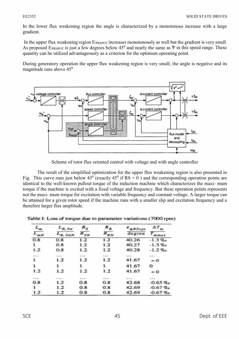
In the lower flux weakening region the angle is characterized by a monotonous increase with a largegradient.
In the upper flux weakening region EѰRSPOT increases monotonously as well but the gradient is very small.As proposed EѰRSPOT is just a few degrees below 450 and nearly the same as Ѱ in this speed range. Thesequantity can be utilized advantageously as a criterion for the optimum operating point.
During generatory operation the upper flux weakening region is very small; the angle is negative and itsmagnitude runs above 450
Scheme of rotor flux oriented control with voltage and with angle controller
The result of the simplified optimization for the upper flux weakening region is also presented inFig. This curve runs just below 450 (exactly 450 if RS = 0 ) and the corresponding operation points areidentical to the well-known pullout torque of the induction machine which characterizes the maxi- mumtorque if the machine is excited with a fixed voltage and frequency. But these operation points representsnot the maxi- mum torque for excitation with variable frequency and constant voltage. A larger torque canbe attained for a given rotor speed if the machine runs with a smaller slip and excitation frequency and atherefore larger flux amplitude.

EE2352 SOLID STATE DRIVES
SCE 46 Dept. of EEE
The robustness of the stator flux angle EѰRSPOT is demonstrated with Table I. In this table the resultsof EѰRSPOT! for a fixed rotor speed are listed which can be obtained if variations of the electrical parameters(factor: 0.8, 1.0, 1.2) are allowed and all 81 combinations are examined. The rows are sorted to increasingEѰRSPOT.In spite of the large variations the maxi- mum and the minimum of EѰRSPOT differ only little fromthe correct value 41.670. For these calculations the saturation of the mutual inductance was neglected andin this case EѰRSPOT is independent of the stator voltage. The last column shows the loss of torque if theinduction machine runs with EѰRSPOT calculated from the detuned parameters. An extreme robustness toparameter uncertainties can be realized.
The current reduction by means of the stator flux angle can be easily implemented in the controlscheme. One solution with little expense is shown in Fig. 7. The flux model delivers additionally anestimated value of the difference to EѰRSPOT is applied to an integrator which operates as an angle controller.Its regulating quantity is the limit of the reference q-current. If (E I > EѰRSPOT) the q-current will be reduceduntil the regulated quantity meets its reference value EѰRSPOT.
The quality of the operation point adjustment depends apparently on the quality of the fluxestimation but at the relevant large rotor speeds a robust flux estimation is not difficult and uncritical.Furthermore, EѰRS coupled closely to the measurable angle Ѱ in this speed range.
4.4 Voltage-source Inverter-driven Induction Motor
A three-phase variable frequency inverter supplying an induction motor is shown in Figure. Thepower devices are assumed to be ideal switches. There are two major types of switching schemes for theinverters, namely, square wave switching and PWM switching.

EE2352 SOLID STATE DRIVES
SCE 47 Dept. of EEE
Square wave inverters
The gating signals and the resulting line voltages for square wave switching are shown in Figure.The phase voltages are derived from the line voltages assuming a balanced three-phase system.
A schematic of the generic inverter-fed induction motor drive.
The square wave inverter control is simple and the switching frequency and consequently,switching losses are low. However, significant energies of the lower order harmonics and large distortionsin current wave require bulky low-pass filters. Moreover, this scheme can only achieve frequency control.For voltage control a controlled rectifier is needed, which offsets some of the cost advantages of the simpleinverter
PWM Principle
It is possible to control the output voltage and frequency of the PWM inverter simultaneously, aswell as optimize the harmonics by performing multiple switching within the inverter major cycle whichdetermines frequency. For example, the fundamental voltage for a square wave has the maximumamplitude (4Vd/π) but by intermediate switching, as shown in Fig. 34.12, the magnitude can be reduced.This determines the principle of simultaneous voltage control by PWM. Different possible strategies forPWM switching exist. They have different harmonic contents. In the following only a sinusoidal PWM isdiscussed.

EE2352 SOLID STATE DRIVES
SCE 48 Dept. of EEE
Inverter gate (base) signals and line-and phase-voltage waveforms
PWM principle to control output voltage.
Sinusoidal PWM
Figure explains the general principle of SPWM, where an isosceles triangle carrier wave offrequency fc is compared with the sinusoidal modulating wave of fundamental frequency f, and the pointsof intersection determine the switching points of power devices. For example, for phase-a, voltage (Va0)is obtained by switching ON Q1 and Q4 of half-bridge inverter, as shown in the figure . Assuming that f<< fc, the pulse widths of va0 wave vary in a sinusoidal manner. Thus, the fundamental frequency iscontrolled by varying f and its amplitude is proportional to the command modulating voltage. The Fourieranalysis of the va0 wave can be shown to be of the form

EE2352 SOLID STATE DRIVES
SCE 49 Dept. of EEE
Va0 = 0.5mVd sin(2 Лft+πφ)+ harmonic frequency terms
Line voltage waves of PWM inverter
Where m = modulation index and φ = phase shift of output, depending on the position of themodulating wave. The modulation index m is defined as
m= VP/VT
Where Vp = peak value of the modulating wave and VT = peak value of the carrier wave. Ideally,m can be varied between 0 and 1 to give a linear relation between the modulating and output wave. Theinverter basically acts as a linear amplifier. The line voltage waveform is shown in Fig.
Current Fed Inverters
CSI classification is based on the structure of the front-end power converter, which could be eithera phase-controlled thyristor rectifier or a PWM current-source rectifier.
A. Phase-Controlled Front-End Rectifiers
These drives use a front-end rectifier based on thyristor-type power switches (Fig. 1), which can be operatedwith either variable or fixed dc-link current. The performance of the drive converter depends on this lastfeature.

EE2352 SOLID STATE DRIVES
SCE 50 Dept. of EEE
Variable DC-Link Current Scheme
The CSI is operated with a fixed pattern, which is usually optimized in terms of harmonic spectrumand switching frequency. Thus, the load voltage harmonic distortion is minimum and constant (Table I).However, the dc-link current must be adjusted through transient changes in firing angle to meet therequirements of the load. The dc voltage, on the other hand, is practically constant and independent of theload torque.
This last feature leads to a constant input current displacement factor and, thereby, a constant overallPF. Also, since the dc-link current tracks the output current, the dc-bus and switch conduction losses arekept to a minimum. Usually, the dc-link inductor is designed to have an acceptable current ripple (5%). Inorder to achieve this value and due to the low-order harmonics produced by the thyristor rectifier (sixth,12th, etc.), the size of the dc inductor becomes quite bulky. This results in a slow system transient response.Also, the supply current has a high distortion factor % due to the low-order harmonics (fifth, seventh, etc.)injected by the thyristor rectifier. Fig shows typical waveforms of the converter. The rectifier phase angleis only adjusted during transient conditions occurring under load speed and torque variations.
(a)
AC drive CSI based on a phase-controlled front-end rectifier
(a) Power topology. (b) Supply phase voltage and supply line current. (c) DC rectifier voltage and dc-linkcurrent. (d) CSI line current and load line voltage. (e) Load phase voltage and load line current.

EE2352 SOLID STATE DRIVES
SCE 51 Dept. of EEE
Fixed DC-Link Current Scheme
Unlike the above control scheme, the CSI is operated with a PWM pattern, which varies as afunction of the CSI modulation index. Therefore, the load voltage harmonic distortion is variable anddepends upon the speed and load torque (Table I). Since the dc-link current is fixed, the different loadpower requirements are obtained by varying the dc-link voltage. To achieve this, the input currentdisplacement factor is continuously adjusted and, thereby, the input PF becomes variable and close to zerofor light loads. Contrary to the variable dc-link current scheme, the dc-bus and switch conduction lossesare always maximum, due to the fact that the dc-link current is always maximum (Table I). Although thedc-link inductor size is as big as the one used in the above scheme, the dynamic response of the load currentis improved, due to the variable PWM pattern approach with time responses to modulation index changesof the order of a sampling period. This scheme also presents a high supply current harmonic distortion, dueto the thyristor rectifier operation (Table I). Typical waveforms shown in Fig are also applicable in thiscase; however, in this mode of operation, the rectifier phase angle is continuously adjusted to maintain aconstant dc-link current, regardless of the load speed and torque.
B. PWM Front-End Rectifiers
Unlike phase-controlled rectifier topologies, this topology uses a PWM rectifier. This allows areduction in the harmonics injected into the ac supply. The rectifier is operated with a fixed dc-link current.Fig. 2 shows typical waveforms of the converter. The PWM pattern is adjusted on a continuous basis tokeep a constant dc-link current. In contrast to topologies based on thyristor front-end rectifiers, the overalldrive input PF is always greater than 0.95, and the total input current harmonic distortion, which dependson the sampling frequency, is typically lower than 10% (Table I). Also, since the output inverter is PWMmodulated, the system has time responses close to the sampling period. However, the dc-bus losses andswitch conduction losses are maximum, since the dc-link current is always equal to its maximum value,regardless of the load speed and torque.

EE2352 SOLID STATE DRIVES
SCE 52 Dept. of EEE
AC drive CSI based on a PWM front-end rectifier
(a) Power topology. (b) Supply phase voltage and supply line current. (c) DC rectifier voltage and dc-linkcurrent. (d) CSI line current and load line voltage. (e) Load phase voltage and load line current.
4.5 Vector Control of AC Induction Machines
Vector control is the most popular control technique of AC induction motors. In special referenceframes, the expression for the electromagnetic torque of the smooth-air-gap machine is similar to theexpression for the torque of the separately excited DC machine. In the case of induction machines, thecontrol is usually performed in the reference frame (d-q) attached to the rotor flux space vector. That’s whythe implementation of vector control requires information on the modulus and the space angle (position)of the rotor flux space vector. The stator currents of the induction machine are separated into flux- andtorque-producing components by utilizing transformation to the d-q coordinate system, whose direct axis(d) is aligned with the rotor flux space vector. That means that the q-axis component of the rotor flux spacevector is always zero:
The rotor flux space vector calculation and transformation to the d-q coordinate system require thehigh computational power of a microcontroller. The digital signal processor is suitable for this task. Thefollowing sections describe the space vector transformations and the rotor flux space vector calculation.
Block Diagram of the Vector Control
Shows the basic structure of the vector control of the AC induction motor. To perform vector control, it isnecessary to follow these steps:
• Measure the motor quantities (phase voltages and currents)
• Transform them to the 2-phase system (α,β) using a Clarke transformation
• Calculate the rotor flux space vector magnitude and position angle
• Transform stator currents to the d-q coordinate system using a Park transformation

EE2352 SOLID STATE DRIVES
SCE 53 Dept. of EEE
• The stator current torque and flux producing components are separately controlled
• The output stator voltage space vector is calculated using the decoupling block
• The stator voltage space vector is transformed by an inverse Park transformation back from the d-qcoordinate system to the 2-phase system fixed with the stator
• Using the space vector modulation, the output 3-phase voltage is generated
Block Diagram of the AC Induction Motor Vector Control
Forward and Inverse Clarke Transformation (a,b,c to α,β and backwards)
The forward Clarke transformation converts a 3-phase system a,b,c to a 2-phase coordinate systemα,β. Figure shows graphical construction of the space vector and projection of the space vector to thequadrature-phase components α,β.

EE2352 SOLID STATE DRIVES
SCE 54 Dept. of EEE
The inverse Clarke transformation goes back from a 2-phase (α,β) to a 3-phase isa, isb, isc system. Forconstant k=2/3, it is given by the following equations:
Forward and Inverse Park Transformation (α,β to d-q and backwards)
The components isα and isβ, calculated with a Clarke transformation, are attached to the statorreference frame α, β. In vector control, it is necessary to have all quantities expressed in the same referenceframe. The stator reference frame is not suitable for the control process. The space vector isβ is rotating ata rate equal to the angular frequency of the phase currents. The components isα and isβ depend on time andspeed. We can transform these components from the stator reference frame to the d-q reference framerotating at the same speed as the angular frequency of the phase currents. Then the isd and isq componentsdo not depend on time and speed. If we consider the d-axis aligned with the rotor flux, the transformationis illustrated in Figure where θfield is the rotor flux position.
Park Transformation
The inverse Park transformation from the d-q to α,β coordinate system is given by the following equations:
Rotor Flux Model
Knowledge of the rotor flux space vector magnitude and position is key information for the ACinduction motor vector control. With the rotor magnetic flux space vector, the rotational coordinate system(d-q) can be established. There are several methods for obtaining the rotor magnetic flux space vector. Theimplemented flux model utilizes monitored rotor speed and stator voltages and currents. It is calculated inthe stationary reference frame (α,β) attached to the stator. The error in the calculated value of the rotor flux,influenced by the changes in temperature, is negligible for this rotor flux model.

EE2352 SOLID STATE DRIVES
SCE 55 Dept. of EEE
The rotor flux space vector is obtained by solving the differential equations (EQ 4-2) and (EQ 4-3), which are resolved into the α and β components. The equations are derived from the equations of theAC induction motor model
4.6 Closed-loop control of induction motor
Closed-loop induction motor drive with constant volts/Hz control strategy

EE2352 SOLID STATE DRIVES
SCE 56 Dept. of EEE
An outer speed PI control loop in the induction motor drive, shown in Figure computes thefrequency and voltage set points for the inverter and the converter respectively. The limiter ensures thatthe slip-speed command is within the maximum allowable slip speed of the induction motor. The slip-speed command is added to electrical rotor speed to obtain the stator frequency command. Thereafter, thestator frequency command is processed in an open-loop drive. Kdc is the constant of proportionalitybetween the dc load voltage and the stator frequency.
4.7 Constant air gap flux control:
1. Equivalent separately-excited dc motor in terms of its speed but not in terms of decoupling of fluxand torque channel.
2. Constant air gar flux linkages
ƛm= Lmim=E1/Ѡs
The rotor flux magnitude and position is key information for the AC induction motor control. With therotor magnetic flux, the rotational coordinate system (d-q) can be established. There are several methodsfor obtaining the rotor magnetic flux. The implemented flux model utilizes monitored rotor speed and statorvoltages and currents. It is calculated in the stationary reference frame (α,β) attached to the stator. The errorin the calculated value of the rotor flux, influenced by the changes in temperature, is negligible for thisrotor flux model

EE2352 SOLID STATE DRIVES
SCE 57 Dept. of EEE
UNIT V
SYNCHRONOUS MOTOR DRIVES
5.1 V/FOFPERMANENTMAGNETS SYNCHRONOUS MOTORS
Constant volt per hertz control in an open loop is used more often in the squirrel cage IMapplications. Using this technique for synchronous motors with permanent magnets offers a big advantageof sensor less control. Information about the angular speed can be estimated indirectly from the frequencyof the supply voltage. The angular speed calculated from the supply voltage frequency ac- cording to (1)can be considered as the value of the rotor angular speed if the external load torque is nothing her than thebreak down torque.
The mechanical synchronous angular speed ωs is proportional to the frequency fs of the supply voltage
Where p is the number of pole pairs.
The RMS value of the induced voltage of AC motors is given as
EE2352 SOLID STATE DRIVES
SCE 58 Dept. of EEE
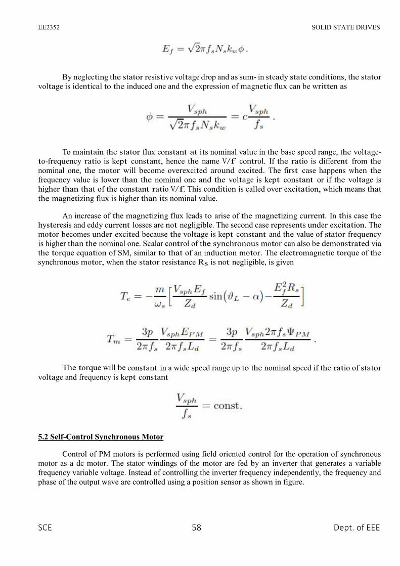
By neglecting the stator resistive voltage drop and as sum- in steady state conditions, the statorvoltage is identical to the induced one and the expression of magnetic flux can be written as
To maintain the stator flux constant at its nominal value in the base speed range, the voltage-to-frequency ratio is kept constant, hence the name V/f control. If the ratio is different from thenominal one, the motor will become overexcited around excited. The first case happens when thefrequency value is lower than the nominal one and the voltage is kept constant or if the voltage ishigher than that of the constant ratio V/f. This condition is called over excitation, which means thatthe magnetizing flux is higher than its nominal value.
An increase of the magnetizing flux leads to arise of the magnetizing current. In this case thehysteresis and eddy current losses are not negligible. The second case represents under excitation. Themotor becomes under excited because the voltage is kept constant and the value of stator frequencyis higher than the nominal one. Scalar control of the synchronous motor can also be demonstrated viathe torque equation of SM, similar to that of an induction motor. The electromagnetic torque of thesynchronous motor, when the stator resistance Rs is not negligible, is given
The torque will be constant in a wide speed range up to the nominal speed if the ratio of statorvoltage and frequency is kept constant
5.2 Self-Control Synchronous Motor
Control of PM motors is performed using field oriented control for the operation of synchronousmotor as a dc motor. The stator windings of the motor are fed by an inverter that generates a variablefrequency variable voltage. Instead of controlling the inverter frequency independently, the frequency andphase of the output wave are controlled using a position sensor as shown in figure.

EE2352 SOLID STATE DRIVES
SCE 59 Dept. of EEE
Field oriented control was invented in the beginning of 1970s and it demonstrates that an inductionmotor or synchronous motor could be controlled like a separately excited dc motor by the orientation of thestator mmf or current vector in relation to the rotor flux to achieve a desired objective. In order for themotor to behave like DC motor, the control needs knowledge of the position of the instantaneous rotor fluxor rotor position of permanent magnet motor. This needs a resolver or an absolute optical encoder. Knowingthe position, the three phase currents can be calculated. Its calculation using the current matrix depends onthe control desired. Some control options are constant torque and flux weakening. These options are basedin the physical limitation of the motor and the inverter. The limit is established by the rated speed of themotor.
Steady State Torque versus Speed
Field Oriented Control of PM Motors:
The PMSM control is equivalent to that of the dc motor by a decoupling control known as fieldoriented control or vector control. The vector control separates the torque component of current and fluxchannels in the motor through its stator excitation.
The vector control of the PM synchronous motor is derived from its dynamic model. Consideringthe currents as inputs, the three currents are:

EE2352 SOLID STATE DRIVES
SCE 60 Dept. of EEE
Where α is the angle between the rotor field and stator current phasor, r ω is the electrical rotor speed
The previous currents obtained are the stator currents that must be transformed to the rotor referenceframe with the rotor speed r ω, using Park’s transformation. The q and d axis currents are constants in therotor reference frames since α is a constant for a given load torque. As these constants, they are similar tothe armature and field currents in the separately excited dc machine. The q axis current is distinctlyequivalent to the armature current of the dc machine; the d axis current is field current, but not in its entirety.It is only a partial field current; the other part is contributed by the equivalent current source representingthe permanent magnet field. For this reason the q axis current is called the torque producing component ofthe stator current and the d axis current is called the flux producing component of the stator current.
Substituting equation above and obtain id and iq in terms of Im as follows
Using equations the electromagnetic torque equation is obtained as given below.
Constant Torque Operation:
Constant torque control strategy is derived from field oriented control, where the maximum possibletorque is desired at all times like the dc motor. This is performed by making the torque producing currentiq equal to the supply current Im. That results in selecting the α angle to be 90 º degrees according to equation.By making the id current equal to zero the torque equation can be rewritten as:

EE2352 SOLID STATE DRIVES
SCE 61 Dept. of EEE
Flux-weakening:
Flux weakening is the process of reducing the flux in the d axis direction of the motor which resultsin an increased speed range.
The motor drive is operated with rated flux linkages up to a speed where the ratio between theinduced emf and stator frequency (V/f) is maintained constant. After the base frequency, the V/f ratio isreduced due to the limit of the inverter dc voltage source which is fixed. The weakening of the field flux isrequired for operation above the base frequency.
This reduces the V/f ratio. This operation results in a reduction of the torque proportional to a changein the frequency and the motor operates in the constant power region.
The rotor flux of PMSM is generated by permanent magnet which cannot be directly reduced asinduction motor. The principle of flux-weakening control of PMSM is to increase negative direct axiscurrent and use armature reaction to reduce air gap flux, which equivalently reduces flux and achieves thepurpose of flux-weakening control.
This method changes torque by altering the angle between the stator MMF and the rotor d axis. Inthe flux weakening region where ωr > ωrated angle α is controlled by proper control of id and iq for the samevalue of stator current. Since iq is reduced the output torque is also reduced. The angle α can be obtainedas:
Flux-weakening control realization
The realization process of equivalent flux-weakening control is as follows,
1) Measuring rotor position and speed ωr from a sensor which is set in motor rotation axis.
2) The motor at the flux weakening region with a speed loop, Te* is obtained from the PI controller.
3) Calculate Iq*

EE2352 SOLID STATE DRIVES
SCE 62 Dept. of EEE
4) Calculate Id* using equation:
5) Calculate α using equation
6) Then the current controller makes uses of the reference signals to control the inverter for the desiredoutput currents.
7) The load torque is adjust to the maximum available torque for the reference speed
5.3 Power Factor Correction Of Permanent Magnet Synchronous Motor Drive With Field OrientedControl Using Space Vector Modulation
Field oriented control demonstrates that, a synchronous motor could be controlled like a separatelyexcited dc motor by the orientation of the stator mmf or current vector in relation to the rotor flux to achievea desired objective. The aim of the FOC method is to control the magnetic field and torque by controllingthe d and q components of the stator currents or relatively fluxe. With the information of the stator currentsand the rotor angle a FOC technique can control the motor torque and the flux in a very effective way.
The main advantages of this technique are the fast response and reduced torque ripple. Theimplementation of this technique will be carried out using two current regulators, one for the direct-axiscomponent and another for the quadrature-axis component, and one speed regulator. There are three PIregulators in the control system. One is for the mechanical system (speed) and two others for the electricalsystem (d and q currents). At first, the reference speed is compared with the measured speed and the errorsignal is fed to the speed PI controller.
This regulator compares the actual and reference speed and outputs a torque command. Once isobtained the torque command, it can be turned into the quadrature-axis current reference, Iq,ref . There is aPI controller to regulate the d component of the stator current. The reference value, Id,ref, is zero since thereis no flux weakening operation. The d component error of the current is used as an input for the PI regulator.Moreover, there is another PI controller to regulate the q component of the current. The reference value is

EE2352 SOLID STATE DRIVES
SCE 63 Dept. of EEE
compared with the measured and then fed to the PI regulator. The performance of the FOC block diagramcan be summarized in the following steps
The performance of the FOC block diagram can be summarized in the following steps:
1. The stator currents are measured as well as the rotor angle.
2. The stator currents are converted into a two-axis reference frame with the Clark Transformation.
3. The α,β currents are converted into a rotor reference frame using Park Transformation
4. With the speed regulator, a quadrature-axis current reference is obtained. The d-current controls the airgap flux, the q-current control the torque production.
5. The current error signals are used in controllers to generate reference voltages for the inverter.
6. The voltage references are turned back into abc domain.
7. With these values are computed the PWM signals required for driving the inverter.
SPACE VECTOR MODULATION
The basis of SVPWM is different from that of sine pulse width modulation (SPWM). SPWM aimsto achieve symmetrical 3-phase sine voltage waveforms of adjustable voltage and frequency, whileSVPWM takes the inverter and motor as a whole, using the eight fundamental voltage vectors to realizevariable frequency of voltage and speed adjustment. SVPWM aims to generate a voltage vector that is closeto the reference circle through the various switching modes of inverter. Fig is the typical diagram of a three-phase voltage source inverter model. For the on- off state of the three-phase inverter circuit, every phasecan be considered as a switch S. Here, SA(t), SB(t) and SC(t) are used as the switching functions for the threephases, respectively.
Diagram of a three phase inverter

EE2352 SOLID STATE DRIVES
SCE 64 Dept. of EEE
The space vector of output voltage of inverter can be expressed as
PMSM Drive with Active Power Factor Correction (Apfc):
PMSM drive with PFC
The above figure shows the block diagram of PMSM drive with Active power Factor Correction.The APFC consists of an energy stored element, switching device and control module. It is commonlyinstalled between the power rectifier and the dc link bus. The main purpose of APFC is to make the inputof the power supply look like a pure resistor. In other words, it is to make the input current waveform inphase with the input voltage waveform so that there is no phase displacement between them. The operationof APFC is basically based on a controller that can output the signal to a switching device to control theenergy being stored or released in the reactive elements. In such a way, the input current waveform can beadjusted. The magnitude and phase of the input current waveforms by proper control can follow that of theinput voltage waveform. Consequently, the power factor improvement can be achieved and further, thevoltage stability can be obtained as well. The dc link voltage for the inverter is obtained from PFC block.The stator currents and rotor position of PMSM are given to the FOC, which controls the flux and torquecomponents.

EE2352 SOLID STATE DRIVES
SCE 65 Dept. of EEE
The current error signals are used in controllers to generate reference voltages Vα and Vβ, which arethe inputs of SVM. Space Vector modulation gives signals required for driving the inverter. By usinginverter three phase supply is given to the PMSM
PFC with Boost Converter Circuit
The above Figure shows the circuit of power factor correction circuit with boost converter. Anuncontrolled diode rectifier with a boost converter is used to convert the single phase AC voltage into aconstant DC link voltage, which is fed to the three phase inverter supplying a PMSM.
The boost converter is the widely used topology for achieving power factor correction. Thisconverter draws nearly unity power factor current from the AC mains and eliminates a harmonic currentwhich regulates the DC link voltage even under fluctuating voltage conditions of AC mains.
This circuit uses a diode bridge rectifier, an inductor which is connected in series with the supply,a switch MOSFET and an output capacitor. The bulk energy storage capacitor sits on the output side of theconverter rather than just after the diode rectifier bridge. The average inductor current which charges thebulk capacitor is proportional to the utility line voltage.
For proper operation, the output voltage must be higher than the peak line voltage and current drawnfrom the line must be proportional to the line voltage. In circuit operation, it is assumed that the inductanceof boost inductor is large so that it can be represented by constant current source and that the output ripplevoltage is negligible so that the voltage across the output filter capacitor can be represented by constantvoltage source.
5.4 DESIGN EQUATIONS OF BOOST POWER FACTOR CORRECTION CIRCUIT
The AC input voltage given to the power factor correction circuit is 100V and input frequency is50Hz. The selection of boost converter components is based on the following equations Maximum inputpower,

EE2352 SOLID STATE DRIVES
SCE 66 Dept. of EEE

EE2352 SOLID STATE DRIVES
SCE 67 Dept. of EEE
5.5 Permanent Magnet Synchronous Motor Black Diagram Of Closed Loop Control
The basic block-diagram of PMSM drive system shown in figure in this figure basic four partdivided in this circuit. All part discuss in briefly in this below section. The below figure shown it is onetype of closed-loop block diagram.
There are four basic component
1. Voltage Source Inverter
2. Pm Synchronous Motor
3. Current Controller
4. Position Sensor
Voltage Source Inverter
Voltage Source Inverters are devices that convert a DC voltage to AC voltage of variable frequencyand magnitude. They are very commonly used in adjustable speed drives and are characterized by a well-defined switched voltage wave form in the terminals. The ac voltage frequency can be variable or constantdepends on the application. Three phase inverters consist of six power switches connected as shown infigure to dc voltage source. An inverter switches must be carefully selected based on the requirements ofoperation, ratings and the application.
Voltage Source Inverter
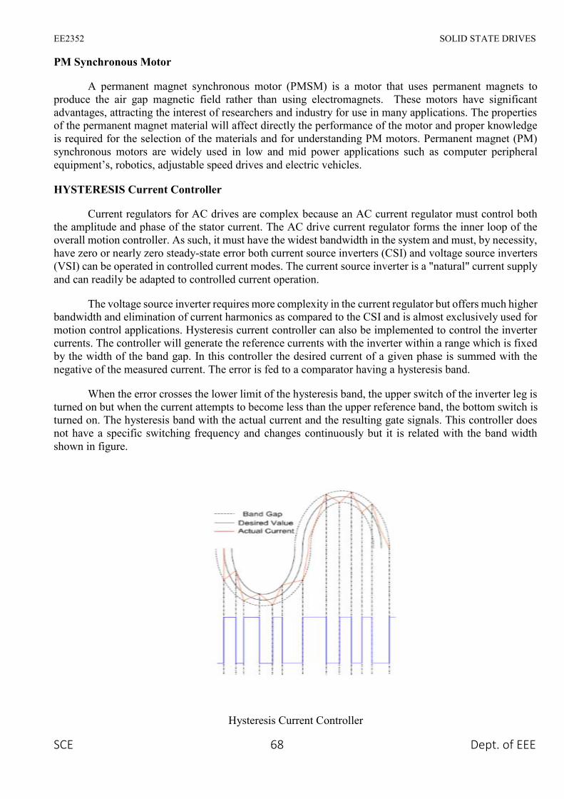
EE2352 SOLID STATE DRIVES
SCE 68 Dept. of EEE
PM Synchronous Motor
A permanent magnet synchronous motor (PMSM) is a motor that uses permanent magnets toproduce the air gap magnetic field rather than using electromagnets. These motors have significantadvantages, attracting the interest of researchers and industry for use in many applications. The propertiesof the permanent magnet material will affect directly the performance of the motor and proper knowledgeis required for the selection of the materials and for understanding PM motors. Permanent magnet (PM)synchronous motors are widely used in low and mid power applications such as computer peripheralequipment’s, robotics, adjustable speed drives and electric vehicles.
HYSTERESIS Current Controller
Current regulators for AC drives are complex because an AC current regulator must control boththe amplitude and phase of the stator current. The AC drive current regulator forms the inner loop of theoverall motion controller. As such, it must have the widest bandwidth in the system and must, by necessity,have zero or nearly zero steady-state error both current source inverters (CSI) and voltage source inverters(VSI) can be operated in controlled current modes. The current source inverter is a "natural" current supplyand can readily be adapted to controlled current operation.
The voltage source inverter requires more complexity in the current regulator but offers much higherbandwidth and elimination of current harmonics as compared to the CSI and is almost exclusively used formotion control applications. Hysteresis current controller can also be implemented to control the invertercurrents. The controller will generate the reference currents with the inverter within a range which is fixedby the width of the band gap. In this controller the desired current of a given phase is summed with thenegative of the measured current. The error is fed to a comparator having a hysteresis band.
When the error crosses the lower limit of the hysteresis band, the upper switch of the inverter leg isturned on but when the current attempts to become less than the upper reference band, the bottom switch isturned on. The hysteresis band with the actual current and the resulting gate signals. This controller doesnot have a specific switching frequency and changes continuously but it is related with the band widthshown in figure.
Hysteresis Current Controller

EE2352 SOLID STATE DRIVES
SCE 69 Dept. of EEE
Position Sensor
Operation of permanent magnet synchronous motors requires position sensors in the rotor shaftwhen operated without damper winding. The need of knowing the rotor position requires the developmentof devices for position measurement. There are four main devices for the measurement of position, thepotentiometer, linear variable differential transformer, optical encoder and resolvers. The ones mostcommonly used for motors are encoders and revolvers. Depending on the application and performancedesired by the motor a position sensor with the required accuracy can be selected.
5.6 VECTOR CONTROL TECHNIQUE
The PMSM control is equivalent to that of the dc motor by a decoupling control known as fieldoriented control or vector control. The vector control separates the torque component of current and fluxchannels in the motor through its stator excitation. The vector control strategy is somewhat similar to thatof the induction motor vector control, except for the following:
1. The slip frequency is zero because the machine always runs at synchronous speed.
2. The magnetizing current Ids =0 because the rotor flux is supplied by the PM.
3. The unit vector generated from an absolute position sensor because, the unlike slipping poles of aninduction motor, the poles are fixed on the rotor.

EE2352 SOLID STATE DRIVES
- 70 -SCE Dept. of EEE
Two Marks Question Bank
UNIT – I
1. What is meant by electrical drives?Systems employed for motion control are called drives and they employ any of the prime movers
such as diesel or petrol engines, gas or steam turbines, hydraulic motors and electric motors forsupplying mathematical energy for motion control. Drives employing electric motion are called electricdrives.
2. What are the requirements of an electric drive?Stable operation should be assured.The drive should have good transient response
3. Specify the functions of power modulator.Power modulator performs one or more of the following four functions.a. Modulates flow of power form the source to the motor in such a manner that motor is
imparted speed-torque characteristics required by the load.b. During transient operations, such as starting, braking and speed reversal, it restricts source
and motor currents within permissible values; excessive current drawn from source mayoverload it or may cause a voltage dip.
4. Mention the different types of drives.1) Group drive 2) Individual drive3) Multimotor drive
5. List the different types of electrical drives.1) dc drives 2) ac drives
6. What are the advantages of electric drives?They have flexible control characteristics. the steady state and dynamic characteristics of electrical
drives can be shaped to satisfy load requirements.1) Drives can be provided with automatic fault detection systems, programmable logic
controllers and computers can be employed to automatically ctrl the drive operations in adesired sequence.
2) They are available in which range of torque, speed and power.3) It can operate in all the four quadrants of speed-torque plane. Electric braking gives smooth
deceleration and increases life of the equipment compared to other forms of braking.4) Control gear required for speed control, starting and braking is usually simple and easy to
operate.
7. What are the functions performed by electric drives?Various functions performed by electric drives include the following.
a. Driving fans, ventilators, compressors and pumps etc.b. Lifting goods by hoists and cranesc. Imparting motion to conveyors in factories, mines and warehouses andd. Running excavators and escalators, electric locomotives, trains, cars, trolley buses, lifts and
drums winders etc.
8. What are the disadvantages of electric drives?The disadvantages of electric drives are
a. Electric drives system is tied only up to the electrified area.

EE2352 SOLID STATE DRIVES
- 71 -SCE Dept. of EEE
b. The condition arising under the short circuits, leakage from conductors and breakdown ofoverhead conductor may lead to fatal accidents.
c. Failure in supply for a few minutes may paralyses the whole system.
9. What are the advantages of group drive over individual drive?The advantages of group drive over individual drive are
a. Initial cost: Initial cost of group drive is less as compared to that of the individualdrive.b. Sequence of operation: Group drive system is useful because all the operations are
stopped simultaneously.c. Space requirement: Less space is required in group drive as compared to individual drive.d. Low maintenance cost: It requires little maintenance as compared to individual drive.
10. What the group drive is not used extensively.Although the initial cost of group drive is less but yet this system is not used extensively because offollowing disadvantages.
a. Power factor: Group drive has low power factorb. Efficiency: Group drive system when used and if all the machines are not working
together the main motor shall work at very much reduced load.c. Reliability: In group drive if the main motor fails whole industry will come to stand still.d. Flexibility: Such arrangement is not possible in group drive i.e., this arrangement is not
suitable for the place where flexibility is the prime factor.e. Speed: Group drive does not provide constant speed.f. Types of machines: Group drive is not suitable fro driving heavy machines such as cranes,
lifts and hoists etc.
11. Write short notes on individual electric drives.In individual drive, each individual machine is driven by a separate motor. This motor also
imparts motion to various other parts of the machine. Examples of such machines are singlespindle drilling machines (Universal motor is used) and lathes. In a lathe, the motor rotates thespindle, moves the feed and also with the help of gears, transmits motion to lubricating and coolingpumps. A three phase squirrel cage induction motor is used as the drive. In many suchapplications the electric motor forms an integral part of the machine.
12. Mention the different factors for the selection of electric drives?1) Steady state operation requirements.2) Transient operation requirements.3) Requirements related to the source.4) Capital and running cost, maintenance needs life.5) Space and weight restriction.6) Environment and location.7) Reliability.
13. Mention the parts of electrical drives.1) Electrical motors and load.2) Power modulator3) Sources
4) Control unit5) Sensing unit
14. Mention the applications of electrical drives

EE2352 SOLID STATE DRIVES
- 72 -SCE Dept. of EEE
Paper mills Electric traction Cement mills Steel mills
15. Mention the types of enclosuresScreen projected typeDrip proof typeTotally enclosed type
16. Mention the different types of classes of dutyContinuous duty, Discontinuous duty, Short time duty, intermittent duty.
17. What is meant by regenerative braking?Regenerative braking occurs when the motor speed exceeds the synchronous speed. In this
case the IM runs as the induction m\c is converting the mechanical power into electrical power whichis delivered back to the electrical system. This method of braking is known as regenerative braking.
18. What is meant by dynamic braking?Dynamic braking of electric motors occurs when the energy stored in the rotating mass is
dissipated in an electrical resistance. This requires a motor to operate as a gen. to convert the storedenergy into electrical.
19. What is meant by plugging?It is one method of braking of IM. When phase sequence of supply of the motor running at the
speed is reversed by interchanging connections of any two phases of stator with respect to supplyterminals, operation shifts from motoring to plugging region.
20. What is critical speed?It is the speed that separates continuous conduction from discontinuous conduction mode.
21. Which braking is suitable for reversing the motor?Plugging is suitable for reversing the motor.
22. Define equivalent current methodThe motor selected should have a current rating more than or equal to the current. It is also
necessary to check the overload of the motor. This method of determining the power rating of themotor is known as equivalent current method.
23. Define cooling time constantIt is defined as the ratio between C and A. Cooling time constant is denoted as Tau.
Tau = C/AWhere C=amount of heat required to raise the temp of the motor body by 1 degree CelsiusA=amount of heat dissipated by the motor per unit time per degree Celsius.
24. What are the methods of operation of electric drives?Steady stateAcceleration including startingDeceleration including starting
25. Define four quadrant operations.The motor operates in two mode: motoring and braking. In motoring, it converts electrical
energy into mechanical energy which supports its motion. In braking, it works as a generator,converting mathematical energy into electrical energy and thus opposes the motion. Motor canprovide motoring and braking operations for both forward and reverse directions.

EE2352 SOLID STATE DRIVES
- 73 -SCE Dept. of EEE
26. What is meant by mechanical characteristics?The curve is drawn between speed and torque. This characteristic is called mechanical
characteristics.
27. Mention the types of brakingRegenerative braking Dynamic brakingPlugging
28. What are the advantage and disadvantages of D.C. drives?The advantages of D.C. drives are,
a. Adjustable speedb. Good speed regulationc. Frequent starting, braking and reversing.
The disadvantage of D.C. drives is the presence of a mechanical commutator which limits themaximum power rating and the speed.
29. Give some applications of D.C. drives.The applications of D.C. drives are,a. Rolling mills b. Paper mills c. Mine winders d. Hoistse. Machine tools f. Traction g. Printing presses h. Excavatorsi. Textile mils j. Cranes
30. Why the variable speed applications are dominated by D.C. drives?The variable speed applications are dominated by D.C. drives because of lower cost, reliability
and simple control.
UNIT – II
TWO MARKS
1. What is the use of flywheel? Where it is used?It is used for load equalization. It is mounted on the motor shaft in compound motor.
2. What are the advantages of series motor?The advantages of series motors are,
a. High starting torqueb. Heavy torque overloads.
3. Define and mention different types of braking in a dc motor?In breaking the motor works as a generator developing a negative torque which opposes the
motion. Types are regenerative braking, dynamic or rheostat braking and plugging or reverse voltagebraking.
4. How the D.C. motor is affected at the time of starting?A D.C. motor is started with full supply voltage across its terminals, a very high current will
flow, which may damage the motor due to heavy sparking at commuter and heating of the winding.Therefore, it is necessary top limit the current to a safe value during starting.
5. List the drawbacks of armature resistance control?In armature resistance control speed is varied by wasting power in external resistors that are
connected in series with the armature. since it is an inefficient method of speed control it was used inintermittent load applications where the duration of low speed operations forms only a smallproportion of total running time.

EE2352 SOLID STATE DRIVES
- 74 -SCE Dept. of EEE
6. What is static Ward-Leonard drive?Controlled rectifiers are used to get variable d.c. voltage from an a.c. source of fixed
voltage controlled rectifier fed dc drives are also known as static Ward-Leonard drive.
7. What is aline commutated inverter?Full converter with firing angle delay greater than 90 deg. is called line commutated inverter.
such an operation is used in regenerative braking mode of a dc motor in which case a back emf isgreater than applied voltage.
8. Mention the methods of armature voltage controlled dc motor?When the supplied voltage is ac,
Ward-Leonard schemesTransformer with taps and un controlled rectifier bridgeStatic Ward-Leonard scheme or controlled rectifierswhen the supply is dc:Chopper control
9. How is the stator winding changed during constant torque and constant horsepoweroperations?
For constant torque operation, the change of stator winding is made form series - star toparallel - star, while for constant horsepower operation the change is made from series-delta toparallel-star. Regenerative braking takes place during changeover from higher to lower speeds.
10. Define positive and negative motor torque.Positive motor torque is defined as the torque which produces acceleration or the positive rate
of change of speed in forward direction. Positive load torque is negative if it produces deceleration.
11. Write the expression for average o/p voltage of full converter fed dc drives?Vm=(2Vm/pi)cospi.........continuous conductionVm=[Vm(cos alpha-cos beta)+(pi+alpha+beta)]/pi] discontinuous conduction
12. What are the disadvantages of conventional Ward-Leonard schemes?Higher initial cost due to use of two additionalm\cs. Heavy weight and size.Needs more floor space and proper foundation. Requiredfrequent maintenance
13. Mention the drawbacks of rectifier fed dc drives?Distortion of supply. Low power factor.Ripple in motor current
14. What are the advantages in operating choppers at high frequency?The operation at a high frequency improves motor performance by reducing current ripple and
eliminating discontinuous conduction.
15. Why self commutated devices are preferred over thyristors for chopper circuits?Self commutated devices such as power MOSFETs power transistors, IGBTs, GTOs and
IGCTs are preferred over thyristors for building choppers because they can be commutated by a lowpower control signal and don't need commutation circuit.

EE2352 SOLID STATE DRIVES
- 75 -SCE Dept. of EEE
16. State the advantages of dc chopper drives?DC chopper device has the advantages of high efficiency, flexibility in control, light
weight, small size, quick response and regeneration down to very low speed.
17. What are the advantages of closed loop c of dc drives?Closed loop control system has the adv. of improved accuracy, fast dynamic response and
reduced effects of disturbance and system non-linearities.
18. What are the types of control strategies in dc chopper? Time ratio control. Current limit control.
19. What are the adv. of using PI controller in closed loop ctrl. of dc drive?Stabilize the drive Adjust the damping ratio at the desired value Makes the steady state speed error close to zero by integral action and filters out
noise again due to the integral action.
20. What are the different methods of braking applied to the induction motor?Regenerative braking Plugging, Dynamic braking.
21. What are the different methods of speed control of IM?Stator voltage control, Supply frequency control, Rotor resistance control, Slip powerrecovery control.
22. What is meant by stator voltage control.?The speed of the IM can be changed by changing the stator voltage. Because the torque is
proportional to the square of the voltage.
23. Mention the application of stator voltage control.This method is suitable for applications where torque demand reduced with speed, which points
towards its suitability for fan and pump drives.
24. Mention the applications of ac drives.AC drives are used in a no. of applications such as fans, blowers, mill run-out tables, cranes,
conveyors, traction etc.
25. What are the three regions in the speed-torque characteristics in the IM?Motoring region (0<=s<=1)Generating region(s<0)Plugging region (1<=s<=2) where s is the slip.
26. What are the advantages of stator voltage control method? The control circuitry is simple Compact size Quick response time There is considerable savings in energy and thus it is economical method as compared
to other methods of speed ctrl.
27. What is meant by soft start?The ac voltage controllers show a stepless control of supply voltage from zero to rated voltage
they are used for soft start for motors.

EE2352 SOLID STATE DRIVES
- 76 -SCE Dept. of EEE
28. List the adv of squirrel cage IM? Cheaper light in weight Rugged in construction More efficient Require less maintenance It can be operated in dirty and explosive environment
29. Define slipThe difference between the synchronous speed (Ns)and actual speed(N)of the rotor is known as slipspeed. the % of slip is gn by,%slip s=[(Ns-N)/Ns]x 100
30. Define base speed.The synchronous speed corresponding to the rated freq is called the base speed.
UNIT – III
TWO MARKS
1. What is meant by frequency control of IM?The speed of IM can be controlled by changing the supply freq because the speed is directly
proportional to supply frequency. This method of speed ctrl is called freq control.
2. What is meant by V/F control l?When the freq is reduced the i/p voltage must be reduced proportionally so as to maintain
constant flux otherwise the core will get saturated resulting in excessive iron loss and magnetizingcurrent. This type of IM behavior is similar to the working of dc series motor.
3. What are the advantages of V/F control? Smooth speed ctrl Small i/p current and improved power factor at low freq. start Higher starting torque for low case resistance
3. What is meant by stator current control?The 3 phase IM speed can be controlled by stator current control. The stator current can be
varied by using current source inverter.
5. What are the 3 modes of region in the adjustable-freq IM drives characteristics? Constant torque region Constant power region High speed series motoring region
6. What are the two modes of operation in the motor?

EE2352 SOLID STATE DRIVES
- 77 -SCE Dept. of EEE
The two modes of operation in the motor are, motoring and braking. In motoring, it convertselectrical energy to mechanical energy, which supports its motion. In braking, it works as a generatorconverting mechanical energy to electrical energy and thus opposes the motion.
7. How will you select the motor rating for a specific application?When operating for a specific application motor rating should be carefully chosen that the
insulation temperature never exceed the prescribed limit. Otherwise either it will lead to itsimmediate thermal breakdown causing short circuit and damage to winding, or it will lead todeterioration of its quality resulting into thermal breakdown in near future.
8. What is braking? Mention its types.The motor works as a generator developing a negative torque which opposes the motion is
called barking.It is of three types. They are,
a. Regenerative braking.b. Dynamic or rheostat braking.c. Plugging or reverse voltage braking.
9. What are the three types of speed control?The three types of speed control as,
a. Armature voltage controlb. Field flux controlc. Armature resistance control.
10. What are the advantages of armature voltage control?The advantages of armature voltage control are,
a. High efficiencyb. Good transient responsec. Good speed regulation.
11. What are the methods involved in armature voltage control?When the supply in A.C.
a. Ward-Leonard schemesb. Transformer with taps and an uncontrolled rectifier bridge.c. Static ward Leonard scheme or controlled rectifiers when the supply in D.C.d. Chopper control.
12. Give some drawbacks and uses of Ward-Leonard drive.The drawbacks of Ward . Leonard drive are.
a. High initial costb. Low efficiency
The Ward-Leonard drive is used in rolling mills, mine winders, paper mills, elevators,machine tools etc.
13. Give some advantages of Ward-Leonard drive.The advantages of Ward-Leonard drive are,
a. Inherent regenerative barking capabilityb. Power factor improvement.
14. What is the use of controlled rectifiers?Controlled rectifiers are used to get variable D.C. Voltage form an A.C. Source of fixed
voltage.

EE2352 SOLID STATE DRIVES
- 78 -SCE Dept. of EEE
15. What is known as half-controlled rectifier and fully controlled rectifier?The rectifiers provide control of D.C. voltage in either direction and therefore, allow
motor control in quadrants I and IV. They are known as fully-controlled rectifiers.The rectifiers allow D.C. Voltage control only in one direction and motor control in
quadrant I only. They are known as half-controlled rectifiers.
16. What is called continuous and discontinuous conduction?A D.C. motor is fed from a phase controlled converter the current in the armature may flow indiscrete pulses in called continuous conduction.A D.C. motor is fed from a phase controlled converter the current in the armature may flowcontinuously with an average value superimposed on by a ripple is called discontinuousconduction.
17. What are the three intervals present in discontinuous conduction mode of single phase half andfully controlled rectifier?
The three intervals present in half controlled rectifier are,a. Duty intervalb. Free, wheeling intervalc. Zero current intervals.
The two intervals present in fully controlled rectifier area. Duty intervalb. Zero current intervals.
18. What is called inversion?Rectifier takes power from D.C. terminals and transfers it to A.C. mains is called inversion.
19. What are the limitations of series motor? Why series motor is not used in tractionapplications now a days?
1. The field of series cannot be easily controlled. If field control is not employed, the seriesmotor must be designed with its base speed equal to the highest desired speed of the drive.
2. Further, there are a number of problems with regenerative braking of a series motor.Because of the limitations of series motors, separately excited motors are now preferred evenfor traction applications.
20. What are the advantages of induction motors over D.C. motors?The main drawback of D.C. motors is the presence of commutate and brushes, which
require frequent maintenance and make them unsuitable for explosive and dirty environments. Onthe other hand, induction motors, particularly squirrel-cage are rugged, cheaper, lighter, smaller,more efficient, require lower maintenance and can operate in dirty and explosive environments.
21. Give the applications of induction motors drives.Although variable speed induction motor drives are generally expensive than D.C. drives,
they are used in a number of applications such as fans, blowers, mill run-out tables, cranes,conveyors, traction etc., because of the advantages of induction motors. Other applicationsinvolved are underground and underwater installations, and explosive and dirty environments.
22. How is the speed controlled in induction motor?The induction motor speed can be controlled by supplying the stator a variable voltage,
variable frequency supply using static frequency converters. Speed control is also possible byfeeding the slip power to the supply system using converters in the rotor circuit, basically onedistinguishes two different methods of speed control.
a. Speed control by varying the slip frequency when the stator is fed from a constantvoltage, constant frequency mains.
EE2352 SOLID STATE DRIVES
- 79 -SCE Dept. of EEE
b. Speed control of the motor using a variable frequency variable voltage motoroperating a constant rotor frequency.
23. How is the speed control by variation of slip frequency obtained?Speed control by variation of slip frequency is obtained by the following ways.
a. Stator voltage control using a three-phase voltage controller.b. Rotor resistance control using a chopper controlled resistance in the rotor circuit.c. Using a converter cascade in the rotor circuit to recover slip energy.d. Using a cyclconverter in the rotor circuit.
24. Mention the effects of variable voltage supply in a cage induction motor.When a cage induction motor is fed from a variable voltage for speed control the followingobservations may be made.
a.The torque curve beyond the maximum torque point has a negative shape. Astable operating point in this region is not possible for constant torque load.
b.The voltage controlled must be capable of withstanding high starting currents. Therange of speed control is rather limited.
c.The motor power factor is poor.
25. Classify the type of loads driven by the motor.The type of load driven by the motor influences the current drawn and losses of the motor
as the slip various. The normally occurring loads area. Constant torque loads.b. Torque varying proportional to speed.c. Torque varying preoperational to the square of the speed.
26. What are the disadvantages of constant torque loads?The constant torque loads are not favored due to increase in the losses linearly with slip
and becoming maximum at s= 1.0. This is obvious form the variation of flux as the voltage isvaried for speed control. To maintain constant torque the motor draws heavy current resulting inpoor torque/ampere, poor efficiency ad poor power factor at low speeds.
27. In which cases, torque versus speed method is suitable.Torque versus speed method is suitable only for the following cases.
a. For short time operations where the duration of speed controls ids defined.b. For speed control of blowers or pumps having parabolic or cubic variations of torque
with speed. This is not suitable for constant torque loads due to increases and heating.
28. How is the speed of a squirrel cage induction motor controlled?The speed of a squirrel cage induction motor can be controlled very effectively by varying
the stator frequency. Further the operation of the motor is economical and efficient, if it operatesat very small slips. The speed of the motor is therefore, varied by varying the supply frequencyand maintaining the rotor frequency at the rated value or a value corresponding to the requiredtorque on the linear portion of the torque-speed curve.
29. Why the control of a three-phase indication motor is more difficult than D.C. motors.The control of a three-phase induction motor, particularly when the dynamic performance involved
is more difficult than D.C. motors. This is due to a. Relatively large internal resistance of theconverter causes voltage fluctuations following load fluctuations because the capacitor cannot beideally large.

EE2352 SOLID STATE DRIVES
- 80 -SCE Dept. of EEE
b. In a D.C. motor there is a decoupling between the flux producing magnetizing current andtorque producing armature current. They can be independently controlled. This is not thecase with induction motors.c. An induction motor is very poorly damped compared to a D.C. motor.
30. Where is the V/f control used?The V/f control would be sufficient in some applications requiring variable torque, such as
centrifugal pumps, compressors and fans. In these, the torque varies as the square of the speed.Therefore at small speeds the required torque is also small and V/f control would be sufficient to drivethese leads with no compensation required for resistance drop. This is true also for the case of theliquid being pumped with minimal solids.
UNIT – IV
TWO MARKS
1. What are the components of the applied voltage to the induction motor?The applied voltage to the induction motor has two components at low frequencies. They are
a. Proportional to stator frequency.b.To compensate for the resistance drop in the stator.
The second component deepens on the load on the motor and hence on rotor frequency.
2. What is indirect flux control?The method of maintaining the flux constant by providing a voltage boost proportional to slip
frequency is a kind of indirect flux control. This method of flux control is not desirable if very gooddynamic behaviour is required.
3. What is voltage source inverter?Voltage source inverter is a kind of D.C. link converter, which is a two stage conversion device.
4. What is the purpose of inductance and capacitance in the D.C. link circuit?The inductance in the D.C. link circuit provides smoothing whereas the capacitance maintains the
constancy of link voltage. The link voltage is a controlled quality.
5. What are the disadvantages of square wave inverter in induction motor drive?Square wave inverters have commutation problems at very low frequencies, as the D.C. linkvoltage available at these frequencies cannot charge the commutating capacitors sufficientlyenough to commutate the thrusters. Those puts a limit on the lower frequency of operation. Toextend the frequency towards zero, special charging circuits must be used.
6. What is slip controlled drive?When the slip is used as a controlled quantity to maintain the flux constant in the motor the drive is
called slip enrolled drive. By making the slip negative (i.e., decreasing the output frequency of theinverter) The machine may be made to operate as a generator and the energy of the rotating parts fedback to the mains by an additional line side converter or dissipated in a resistance for dynamic barking.By keeping the slip frequency constant, braking at constant torque and current can be achieved.Thus braking is also fast.
7. What are the effects of harmonics in VSI fed induction motor drive?The motor receives square wave voltages. These voltage has harmonic components. The
harmonics of the stator current cause additional losses and heating. These harmonics are alsoresponsible for torque pulsations. The reaction of the fifth and seventh harmonics with the fundamental

EE2352 SOLID STATE DRIVES
- 81 -SCE Dept. of EEE
gives rise to the seventh harmonic pulsations in the torque developed. For a given induction motor fedfrom a square wave inverter the harmonic content in the current tends to remain constantindependent of input frequency, with the rang of operating frequencies of the inverter.
8. What is a current source inverter?In a D.C. link converter, if the D.C. link current is controlled, the inverter is called a current
source inverter, The current in the D.C. link is kept constant by a high inductance and he capacitanceof the filter is dispensed with . A current source inverter is suitable for loads which present a lowimpedance to harmonic currents and have unity p.f.
9. Explain about the commutation of the current source inverter.The commutation of the inverter is load dependent. The load parameters form a part of the
commutation circuit. A matching is therefore required between the inverter and the motor. Multimotoroperation is not possible. The inverter must necessarily be a force commutated one as the inductionmotor cannot provide the reactive power for the inverter. The motor voltage is almost sinusoidal withsuperimposed spikes.
10. Give the features from which a slip controlled drive is developed.The stator current of an induction motor operating on a variable frequency, variable voltage
supply is independent of stator frequency if the air gap flux is maintained constant. However, it is afunction of the rotor frequency. The torque developed is also a function of rotor frequency. The torquedeveloped is also a function of rotor frequency only. Using these features a slip controlled drive can bedeveloped employing a current source inverter to feed an induction motor.
11. How is the braking action produced in plugging?In plugging, the barking torque is produced by interchange any two supply terminals, so that the
direction of rotation of the rotating magnetic field is reversed with respect to the rotation of the motor.The electromagnetic torque developed provides the braking action and brings the rotor to a quick stop.
12. Where is rotor resistance control used?Where the motors drive loads with intermittent type duty, such as cranes, ore or coal unloaders,
skip hoists, mine hoists, lifts, etc. slip-ring induction motors with speed control by variation ofresistance in the rotor circuit are frequently used. This method of speed control is employed for amotor generator set with a flywheel (Ilgner set) used as an automatic slip regulator under shock loadingconditions.
13. What are the advantages and disadvantages of rotor resistance control?Advantage of rotor resistance control is that motor torque capability remains unaltered even at low
speeds. Only other method which has this advantage is variable frequency control. However, cost ofrotor resistance control is very low compared to variable frequency control.
Major disadvantage is low efficiency due to additional losses in resistors connected in the rotorcircuit.
14. Where is rotor resistance control used?Where the motors drive loads with intermittent type duty, such as cranes, ore or coal unloaders,
skip hoists, mine hoists, lifts, etc. slip-ring induction motors with speed control by variation ofresistance in the rotor circuit are frequently used. This method of speed control is employed for amotor generator set with a flywheel (Ilgner set) used as an automatic slip regulator under shockloading conditions.
15. What are the advantages and disadvantages of rotor resistance control?
EE2352 SOLID STATE DRIVES
- 82 -SCE Dept. of EEE
Advantage of rotor resistance control is that motor torque capability remains unaltered even atlow speeds. Only other method which has this advantage is variable frequency control. However,cost of rotor resistance control is very low compared to variable frequency control.
Major disadvantage is low efficiency due to additional losses in resistors connected in the rotorcircuit.
16. How is the resistance in the output terminals of a chopper varied?The resistance connected across the output terminals of a chopper can be varied form O to R by
varying the time ratio of the chopper. When the chopper is always OFF, the supply is always connectedto the resistance R. The time ratio in this case is zero and the effective resistance connected in R.Similarly when the chopper is always ON, the resistance is short circuited. The time ratio in the case isunity and the effective resistance connected is 0. Hence by varying the time ratio from 0 to 1, thevalue of resistance can be varied from R to O.
17. What is the function of inductance L and resistance R in the chopper resistance circuit?A smoothing inductance L is used in the circuit to maintain the current at a constant value. Any short
circuit in the chopper does not become effective due to L.The value of R connected across the chopper is effective for all phases and its value can be related
to the resistance to be connected in each phase if the conventional method has been used. The speedcontrol range is limited by the resistance.
18. What are the disadvantages and advantages of chopper controlled resistance in the rotorcircuit method?
The method is very inefficient because of losses in the resistance. It is suitable for intermittentloads such as elevators. At low speeds, in particular the motor has very poor efficiency. The rotorcurrent is non-sinusoidal. They harmonics of the rotor current produce torque pulsations. These havea frequency which is six times the slip frequency.
Because of the increased rotor resistance, the power factor is better.
19. How is the range of speed control increased?The range of speed control can be increased if a combination of stator voltage control and rotor
resistance control is employed. Instead of using a high resistance rotor, a slip ring rotor with external rotorresistance can be used when stator voltage control is used for controlling the speed.
20. Why the static scherbius drive has a poor power factor?Drive input power is difference between motor input power and the power fed back. Reactive input
power is the sum of motor and inverter reactive power. Therefore, drive has a poor power factorthroughout the range of its options.
21. How is super synchronous speed achieved?Super synchronous speed can be achieved if the power is fed to the rotor from A.C. mains. This
can be made possible by replacing the converter cascade by a cycloconverter. A cycloconverterallows power flow in either direction making the static sherbets drive operate at both sub and suppersynchronous speeds.
22. Give the features of static scherbius driveThe torque pulsations and other reactions are minimal. The performance of the drive improves
with respect to additional losses and torque pulsations. A smooth transition is possible from sub to supersynchronous speeds without any commutation problems. Speed reversal is not possible. A step uptransformer may be interposed between the lines and the converter, to reduce the voltage rating of theconverter.
EE2352 SOLID STATE DRIVES
- 83 -SCE Dept. of EEE
23. Where is Kramer electrical drive system used?Some continuous rolling mills, large air blowers, mine ventilators, centrifugal pumps and any other
mechanisms including pumps drives of hydraulic dredgers require speed adjustment in the range from 15to 30% below or above normal. If the induction motor is of comparatively big size (100 to 200 KW) itbecomes uneconomical to adjust speed by mean's pf external resistances due to copper losses as slippower is wasted as heat in the retort circuit resistance. In these case , the Kramer electrical drive systemis used , where slip power recovery takes places.
24. What is the use of sub synchronous converter cascades?Sub synchronous converter cascades have been used, till now, in applications requiring one
quadrant operation. These can be employed for drives where at least one electrical barking
is required. A four quadrant operation can also be made possible in these cascades, using suitableswitching.
25. How is the speed control obtained in static Kramer drive?For speed control below synchronous speed, the slip power is pumped back to the supply, where as
for the case of speed above synchronous speed, additional slip power is injected into the rotor circuit.
26. What is static Kramer drive?Instead of wasting the slip power in the rotor circuit resistance, it can be converted to 60 Hz A.C.
and pumped back to the line. The slip power controlled drive that permits only a sub synchronous rangeof speed control through a converter cascade is know as static Kramer drive.
27. What is the use and functions of step down transformer is static Kramer drive?For a restricted speed range closer to synchronous speed, the system power factor can be further
improved by using a step -down transformer.The step-down transformer has essentially two functions: besides improving the line power factor, italso helps to reduce the converter power ratings.
28. What are the advantages of static Kramer drive?The static Kramer drive has been very popular in large power pump and fan-type drives, where
the range of speed control is limited near, but below the synchronous speed. The drive system is veryefficient and the converted power rating is low because t has to handle only the slip power, In fact, thepower rating becomes lower with a more restricted range of speed control. The additional advantages arethat the drive system has D.C. machine like characteristics and the control is very simple.
29. What are the causes of harmonic currents in static Kramer drive?The rectification of slip power causes harmonic currents in the rotor, and these harmonics are
reflected to the stator by the transformer action of the machine. The harmonic currents are also injectedinto the A.C. line by the inverter. As a result, the machine losses are increased and some amount ofharmonic torque is produced. Each harmonic current in the rotor will create a reading magnetic filed andits direction of rotation will depend on the order pf the harmonic.
UNIT – V
TWO MARKS
1. Give the four modes of operation of a Scherbius driveThe four modes of operation of static Scherbius drive are,
Sub synchronous motoring.Sub synchronous regeneration

EE2352 SOLID STATE DRIVES
- 84 -SCE Dept. of EEE
Super synchronous motoringSuper synchronous regeneration
2. Give the use of synchronous motors.Synchronous motors were mainly used in constant speed applications. The development of
semiconductor variable frequency sources, such as inverters and cycloconverters, has allowed theiruse in draft fane, main line traction, servo drives, etc.
3. How are the stator and rotor of the synchronous motor supplied?The stator of the synchronous motor is supplied from a thyristor power converter capable of
providing a variable frequency supply. The rotor, depending upon the situation, may beconstructed with slip rings, where it conforms to a conventional rotor. It is supplied with D.C.through slip rings. Sometimes rotor may also be free from sliding contacts (slip rings), in which casethe rotor is fed from a rectifier rotating with rotor.
4. What is the difference between an induction motor and synchronous motor?An induction motor operates at lagging power factor and hence the converter supplying the same
must invariable is a force commutated one. A synchronous motor, on the other hand, can be operatedat any power factor by controlling the field current.
5. List out the commonly used synchronous motors.Commonly used synchronous motors are,
a. Wound field synchronous motors.b. Permanent magnet synchronous motorsc. Synchronous reluctance synchronous motors.d. Hysterias motors.
6. Mention the main difference between the wound field and permanent magnet motors.When a wound filed motor is started as an induction motor, D.C. field is kept off. In case of a
permanent magnet motor, the field cannot be 'turned off’.
7. Give the advantages and applications of PMSM.The advantages of PMSM are,
a. High efficiency b. High power factorc. Low sensitivity to supply voltage variations.
The application of PMSM is that it is preferred of industrial applications with large duty cyclesuch as pumps, fans and compressors.
8. Give the uses of a hysteresis synchronous motor.Small hysteresis motors are extensively used in tape recorders, office equipment and fans. Because
of the low starting current, it finds application in high inertia application such as gyrocompasses andsmall centrifuges.
9. Mention the two modes employed in variable frequency controlVariable frequency control may employ and of the two modes.
a. True synchronous mode b. Self-controlled mode10. Define load commutation
Commutation of thyristors by induced voltages pf load is known as load commutation.
11. List out the advantages of load commutation over forced commutation.Load commutation has a number of advantages over forced commutation

EE2352 SOLID STATE DRIVES
- 85 -SCE Dept. of EEE
It does not require commutation circuitsFrequency of operation can be higherIt can operate at power levels beyond the capability of forced commutation.
12. Give some application of load commutated inverter fed synchronous motor drive.Some prominent applications of load commutated inverter fed synchronous motor drive are
high speed and high power drives for compressors, blowers, conveyers, steel rolling mills, main-linetraction and aircraft test facilities.
13. How the machine operation is performed in self-controlled mode?For machine operation in the self-controlled mode, rotating filed speed should be the same as
rotor speed. This condition is relaised by making frequency of voltage induced in the armature.Firning pulses are therefore generated either by comparison of motor terminal voltages or by rotorposition sensors.
14. What is meant by margin angle of commutation?The difference between the lead angle of firing and the overlap angle is called the margin angle of
commutation. If this angle of the thyristor, commutation failure occurs. Safe commutation is assured ifthis angle has a minimum value equal to the turn off angle f the thyristor.
15. What are the disadvantages of VSI fed synchronous motor drive?VSI synchronous motor drives might impose fewer problems both on machine as well as on the
system design. A normal VSI with 180° conduction of thyristors required forced commutation andload commutation is not possible.
16. How is PNM inverter supplied in VSI fed synchronous motor?When a PWM inverter is used, two cases may arise the inverter may be fed from a constant D.C.
source in which case regeneration is straight forward. The D.C. supply to the inverter may be obtainedform a diode rectifier. In this case an additional phase controlled converter is required on the line side.
17. What is D.C. link converter and cycloconverter?D.C. link converter is a two stage conversion device which provides a variable voltage, variable
frequency supply.Cycloconverter is a single stage conversion device which provides a Variable voltage, variable
frequency supply.
18. What are the disadvantages of cycloconverter?A cycloconverter requires large number of thyristors and ts control circuitry is complex. Converter
grade thyristors are sufficient but the cost of the converter is high.
19. What are the applications of cycloconverter?A cycloconverter drive is attractive for law speed operation and is frequently employed in large,
low speed reversing mils requiring rapid acceleration and deceleration. Typical applications arelarge gearless drives, e.g. drives for reversing mills, mine heists, etc.
20. Give the application of CSI fed synchronous motor.Application of this type of drive is in gas turbine starting pumped hydroturbine starting, pump and
blower drives, etc.
21. What are the disadvantages of machine commutation?The disadvantages of machine commutation are,
a.Limitation on the speed range. b. The machine size is large

EE2352 SOLID STATE DRIVES
- 86 -SCE Dept. of EEE
c. Due to overexciting it is underutilized.
22. What is the use of an auxiliary motor?Sometimes when the power is small an auxiliary motor can be used to run up the synchronous
motor to the desired speed.
23. What are the advantages of brushless D.C. motor?The brushless D.C. motor is in fact an inverter-fed self controlled permanent synchronous motor
drive. The advantages of brushless D.C. motor are low cost, simplicity reliability and goodperformance.
24. When can the synchronous motor be load commutated?When the synchronous motor operates at a leading power factor thyristors of load side converter
can be commutated by the motor induced voltages same way as the thyristors of a line commutatedconverter are commutated by line voltages.
25. What are the characteristics of self controlled mode operated synchronous motor?a) It operates at like dc motor also commutator less motor.b) These machines have better stability behavior.c) Do not have oscillatory behavior.
26. What are the characteristics of true synchronus mode operated synchronous motor?The motor behaves like conventional synchronous motor i.e) hunting oscillations exists.
The change in frequency is slow enough for rotor to truck the changes.Multi motor operation is possible here.
27. What is meant by sub synchronous speed operation?The sub synchronous speed operation means the SRIM speed can be controlled below the
synchronous speed. i.e) the slip power is fed back to the supply.
28. What is meant by super synchronous speed operation?The super synchronous speed operation means the SRIM speed can be controlled above the
synchronous speed. i.e) the supply is fed back to the rotor side.
29. What are the two types of static scherbius system?a) DC link static scherbius system b) Cyclo converter scherbius system