a computer architecture for intelligent machines · pdf filew m r a computer architecture for...
TRANSCRIPT
[ =
n
. .
A COMPUTER ARCHITECTURE FOR
INTELLIGENT MACHINES
l
by
D.R. Lefebvre and G.N. Safidis
m
Rensselaer Polytechnic Institute
Electrical, Computer, and Systems Engineering
Troy, New York 12180-3590
December, 1991
CIRSSE REPORT #108
7 =
m
https://ntrs.nasa.gov/search.jsp?R=19930010158 2018-05-06T12:36:34+00:00Z
w
m
r
A Computer Architecture for Intelligent Machines
D.R. Lefebvre G.N. Saridis
Electrical, Computer, and Systems Engineering Department
Rensselaer Polytechnic Institute
Troy, New York 12180-3590
Abstract
" The Theory of Intelligent Machines proposes a hierarchical organization for the functions of an au-
tonomous robot based on the Principle of Increasing Precision With Decreasing Intelligence. An analytic
formulation of this theory using information-theoretic measures of uncertainty for each level of the intelligent
machine has been developed in recent years. This paper presents a computer architecture that implements the
lower two levels of the intelligent machine. The architecture supports an event-driven programming paradigm
that is independent of the underlying computer architecture and operating system. Details of Execution Level
controllers for motion and vision systems are addressed, as well as the Petri net transducer software used to
implement Coordination Level functions. Extensions to UNL¥ and VxWorks operating systems which enable
the development of a heterogeneous, distributed application are described. A case study illustrates how this
computer architecture integrates real-time and higher-level control of manipulator and vision systems.
1 -'Introduction
The Theory of Intelligent Machines, as proposed in [8], describes a hierarchical organization of the func-
tions of an autonomous robot into three levels: an Execution £evel containing the hardware and basic control
functions, a Coordination £evel integrating the capabilities of the intelligent machine across hardware sys-
tems, and an Organization Level providing higher-level planning and reasoning capabilities. The nature of the
intelligent machine levels are distinctly different with the Execution Level dominated by control functions,
the Coordination Level characterized by operations research issues, and the Organization Level employing
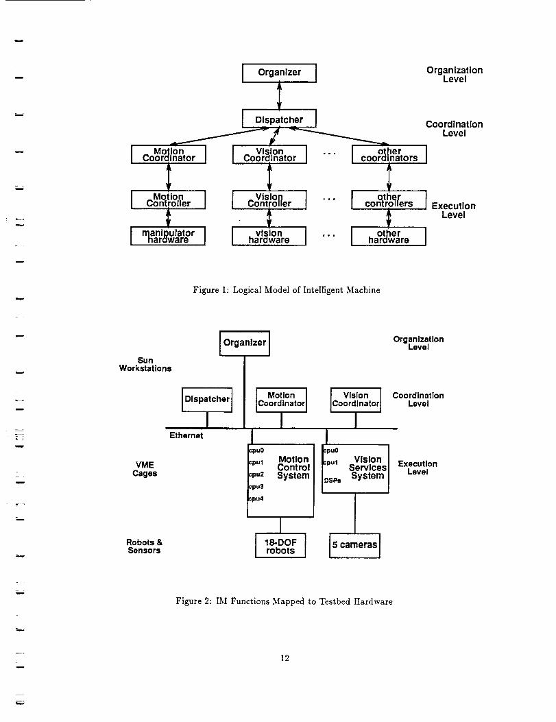
artificial intelligence techniques. A diagram of the intelligent machine (IM) is shown in Figure 1. In this
model, robotic functions and data are organized in the hierarchy according to the principle of Increasing
Precision With Decreasing Intelligence [12][9]. Specifically, higher-level reasoning is performed on abstract
information, to which actual data is instantiated at run-time. Detailed run-time information is maintained
at the lowest Execution Level and only status information is propagated upward through the hierarchy.
Research in the Center for Intelligent Robotic Systems for Space Exploration (CIRSSE) at Rensselaer
Polytechnic Institute over the past several years has addressed the analytic formulation of the Theory of
Intelligent Machines. An information theoretic approach has been adopted using entropy as a measure of
uncertainty (or inversely, information) at each level of the hierarchy. Thus the "intelligent machine problem"
is formulated as an optimal control problem at the Execution Level, a linguistic decision making problem
[11][16] at the Coordination Level, and a neural net relaxation problem [5][10] at the Organization Level.
With the theory in place, CIRSSE began in 1991 to address the issue of implementing the intelligent machine
structure. The computer architecture that has been built to support this research is the focus of this paper.
_-:_
l •
L
w
w
w
The paper is organized as follows. Section 2 describes the mapping of the intelligent machine model to
robotic hardware and computers. Section 3 presents the CIRSSE Testbed Operating System (CTOS) that
was developed to provide a uniform programming interface for the heterogeneous computing environment.
Motivation for and general design details of the Execution Level control systems for the manipulator and
vision systems are treated in sections 4 and 5, respectively. Petri net transducer software and development of
Coordination Level functions is covered in section 6. And, section 7 presents a case study that illustrates how
this computer architecture integrates real-time and higher-level control of manipulator and vision systems.
2 Mapping Intelligent Machine Model to HardwareThe testbed hardware at CIRSSE consists of an 18-DOF manipulator subsystem, a 5 camera vision
subsystem, their associated control computers, and several UNIX workstations. The 18-DOF manipulator
is built from two 6-DOF PUMA robots (a PUMA 560 and a PUMA 600) mounted on a custom-built robot
transporter with two 3-DOF carts. The carts travel along a 12 foot linear track and provide 4-450 of tilt
and 5=150 ° of rotation. Manipulator harclware may be configured as two independent 6- or 9-DOF robot
arms with a large work volume for assembly experiments, or as an 18-DOF system for cooperative two-arm
applications. This manipulator subsystem is controlled by a Motion Control System (MCS), developed at
CIRSSE, executing on a dedicated VME cage that is interfaced to the Unimation controller Q-bus, thus
bypassing the vendor's controller. MCS software was developed to support a wide range of research into
control of multiple manipulators, and integration of IM functions.
The vision subsystem has five cameras that may be used individually or pairwise, a laser scanner for
pointing or structured light, and a (VME-based) Datacube image processing system. A Vision Services
System (VSS) has been developed to control the vision subsystem and to integrate it into the CIRSSE
testbed. Like the MCS, the VSS was designed to be a flexible platform for research.
Additional processing capabilities are provided by four UNIX workstations (predominantly Sun 4 and
Sparc Stations) attached to the CIRSSE Ethernet backbone which connects all of the testbed subsystems.
A schematic diagram of the CIRSSE testbed hardware is shown in Figure 2.
A mapping of intelligent machine functions to the testbed hardware, also shown in Figure 2, assigns Ex-
ecution Level functions of motion and vision control to the VME cages and higher-level Coordination and
Organization functions to the UNIX workstations. The primary rationale for this division is that control
functions must execute in a real-time environment while coordination and planning functions execute at a
"human time scale" supportable by UNIX. The VxWorks operating system is used on the VME cages, and
forms the basis for MCS and VSS. While VxWorks provides an excellent real-time environment for imple-
mentation of control functions, it offers only low-level support (UNIX-compatible sockets) for communication
between the processors on the VME cage or between the VME cage and other chassis on the network. UNIX
has a similarly limited choice of communication methods between chassis (specifically sockets or System \"
messages).
Clearly, the intelligent machine organization proposed in Figure 2 is an heterogeneous, distributed ap-
plication -- spanning many processors, using two different operating systems, and dealing with time scales
ranging from 5 ms control loops to path planning performed aperiodically. To cope with these demands.
extensions to UNIX and VxWorks were developed that affect a communication layer between the operating
system and the application, and produce a uniform programming interface for developing event-driven tasks.
These operating system extensions are called the CIRSSE Testbed Operating System (CTOS) and are tile
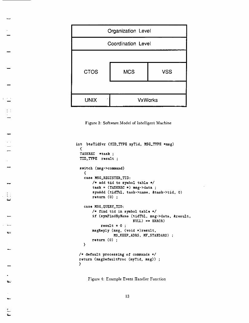
subject of the next section. The researcher is now presented with the straight-forward software model of the
intelligent machine shown in Figure 3.

u
=
!
hk
t
u
w
3 CIRSSE Testbed Operating SystemThe motivation for developing the CIRSSE Testbed Operating System (CTOS) was to enable researchers
to build distributed applications that access the CIR.SSE testbed hardware. A simple, uniform programming
interface was desired which would encourage the development of modular functions that could be interchanged
-- to construct applications from standard components -- and moved among processors -- to balance loads.
In broad terms, CTOS supports three objectives: 1) distribution of tasks, 2) communication between
tasks, and 3) synchronization of tasks and the application. An event-driven environment was implemented
in which tasks execute independently and in parallel, and communicate by exchanging messages. The
interface to CTOS is through five services; three of which are available on both UNIX and VxWorks, and
two for real-time programming in VxWorks:
Bootstrap service loads and initializes software modules on all processors involved in the application.
The distribution of tasks, including.most CTOS system tasks, is specified via configuration files. A task
may be moved from one processor to another simply by revising the configuration file and rebooting
the application -- no recompilation or relinking is required. Additionally, this service broadcasts
messages to all tasks to synchronize three startup phases for the distributed application.
Task identification service assigns a unique identification to every task created in the application and
associates it with the symbolic name of the task specified in the configuration file. The task id is
used to route messages to the task. Another task's id can be found from its symbolic name through
a request to this service.
Message passing service is the primary communication mechanism between event handler tasks. When
CTOS is started sockets are open between all processors on a VME cage, and between all UNIX
workstations and VME cages used by the application. However the user need not know where tasks
are located, from the users' viewpoint the same message service is used independent of the location
of the receiver since the message is essentially addressed via the receiver's symbolic name.
Synchronization service provides high frequency, low latency execution of real-time software functions
on a VME cage. This service is used primarily by the lowest-level functions of MCS such as control
algorithms and hardware interfaces.
Inter-processor blocking service constitutes a second faster-but-limited communication mechanism
between processors on a VME cage based on a "distributed semaphore." It is the foundation for the
synchronization service.
The central objects of CTOS are messages and event handler tasks; these are key to understanding the
system. Messages are 16 byte data structures that contain the task id of receiving and sending tasks,
a command indicating the function of the message, a pointer to additional data and its size, and flags to
specify message handling options. When messages are sent between chassis (an individual UNIX workstation
or a VME cage) the additional message data is transmitted immediately after the message itself; whereas
shared memory techniques are used for messages within a chassis. Management of message data is performed
by CTOS, and so is transparent to the user. Message handling flags can specify that messages are to be
routed at high priority, that the sending task is to wait for a reply from the receiving task, and which task
"owns" the data pointed to by the message.
CTOS users write applications as a collection of event handler tasks which, as discussed earlier, may be
distributed among many processors, and which execute in parallel. An event handler task, or simply "task",
m
m
::= _-
L--
_z
m
l
m_mw
= =
is an instantiation of an event handler function. The CTOS message passing service manages a message
queue for each event handler task, and calls the event handler function when a message arrives.
All event handler functions have the same general format shown in Figure 4. Specifically, the task id
of that instantiation of the function and a pointer to the received message are passed to the function.
Typically the function decodes the message command to determine the processing being requested, performs
the processing, passes the processed message and any unrecognized message to default processing, and then
exits. Because multiple tasks on a single processor may use the same function, these event handler functions
must be reentrant. Requesting service from another task is as simple as sending a message as suggested by
the example in Figure 5. Figures 4 and 5 illustrate one action of the task identification service mentioned
above.
4 Motion Control System
One of the more significant development efforts at CIRSSE has been the production of a Motion Control
System (MCS). After a review of control systems available from university [3][15][14] and NASA [1] sources
it was recommended that a new system be developed in-house, rather than adapting an existing system or
contracting for a custom-built system. Desired functionality, available hardware, and CIRSSE's research
agenda were the primary factors favoring an in-house development. These positive factors offset concerns
over the size of the effort and timing. In total, the specification, design and implementation of CTOS and
core MCS functions required approximately 1.6 man-years of work over a 9 month period -- roughly evenly
split between CTOS and MCS [18].
Figure 6 is a diagram of the organization of MCS. It is designed with a layered structure and has well
defined interfaces between layers so that modules can be replaced independently. The lowest-level testbed
interface layer contains the channel drivers that effect a hardware-independent interface for the upper layers
of MCS. Each robot joint and external sensor of the manipulator subsystem is assigned a slot in the interface;
thus presenting an hardware-independent view of the testbed. For example, a 9-DOF manipulator can be
configured from 6 DOF of a PUMA plus 3 DOF from the robot transporter. The next layer up is the motion
control layer where controller algorithms compute control torques based on current joint data read from
the testbed interface layer and desired setpoints supplied by the motion planning layer. Both the testbed
interface and motion control layers are composed of synchronous tasks executing at the servo rate, e.g. every
4.5 ms. The role of the motion planning layer is to generate a trajectory for implementation by the motion
control layer. Trajectory setpoints are typically calculated at a frequency that is a multiple of the servo
frequency. Requests for motion along new path segments arrive at the motion planning layer asynchronously
from the client interface layer. The client interface layer presents the primary means of access for users who
wish to use the manipulator subsystem without dealing with low-level MCS functions. The Coordination
Level of the IM would move the robot via calls to the client interface layer, for example.
To coordinate the operation of the MCS, a state manager spans the layers of the system. The duties of
the state manager are 1) to ensure that the components of MCS are present and properly configured; 2) to
allocate resources and prevent contention, e.g. two tasks attempting to move the robot in different directions;
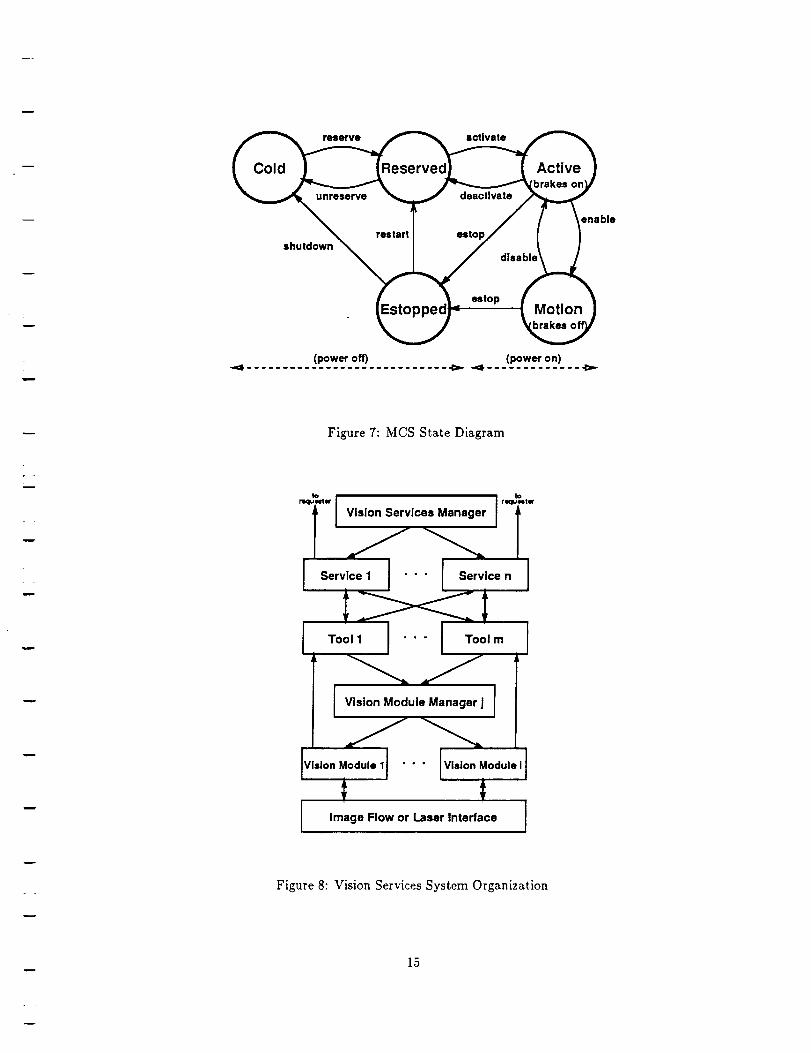
and 3) to enforce the transitions between states of the manipulator subsystem in an orderly manner. The
state manager allows transitions between five states as shown in Figure 7. The only nonobvious state is the
reserved state which is used to ensure that the DOFs of the manipulator have been properly allocated prior
to power on. The five MCS states correspond to the three physical states of "power off", "power on, brakes
on", and "power on, brakes off." Power is off for cold, reserved, and estopped states; power and brakes are
on for the active state; and the brakes are off for motion state.
The functional requirements set for MCS have resulted in a control system with several characteristic,
and in some instances unique, features:
m
w
m
w
!
r
m
o
w
w
L
MCS is a VME-based multiprocessor, real-time control system. Its real-time capabilities are derived
from VxWorks, while interprocessor coordination is supplied by CTOS. Services are provided to build
distributed functions such as a control algorithm that executes on multiple processors.
MCS is part of an heterogeneous, distributed, open architecture that enables integration of motion
control functions with vision services and the higher level functions of the IM. MCS was codeveloped
with CTOS and established many of CTOS's requirements.
* MCS is highly modular with clearly separated motion control operations and easily interchanged
modules performing these operations. Essentially, each operation is one or more event handler task.
Ezpandability of MCS is ensured by the open architecture of CTOS. As an example, collision detection
software developed in a separate CIRSSE research project was easily integrated into MCS to run at
real-time -- with no modification to the existant MCS core functions.
MCS configuration is data-driven; e.g. processor load may be balanced by redistributing tasks, or the
system can be reconfigured for a different number of processors through changes to a configuration
file. This feature is also expected to enhance the portability of MCS.
Multiple manipulators are supported; for instance, the CIRSSE testbed has 3 manipulators -- two
PUMAs and the transporter. MCS implements a uniform interface to all the DOFs so that the 18
DOF of CIRSSE's testbed may be partitioned into three 6-DOF, or two 9-DOF, or one 18-DOF
manipulator(s).
MCS has user interfaces to all layers to support a wide range of research. Coupled with its modular
design, this feature allows modification of an individual module without disrupting higher or lower
layers of MCS. Thus, MCS supports the reseacher developing a new control algorithm as well as those
working two-arm cooperative control or the higher levels of the IM.
The above list stresses the architectural aspects of MCS rather than the usual features of a control system
such as trajectory generation methods or control laws supported. The reason for this selectivity is to highlight
the modular nature of CTOS. To set up an experiment, configuration files are written to specify configuration
of manipulator DOFs, choices of control algorithm module and trajectory generation module to be loaded,
speeds of servo loops and other synchronous processes, etc. The experimenter can configure MCS to include
his own module and use standard modules for the remaining components of the control system, such as
hardware drivers or client interface. At present canonical versions of controller and trajectory generator
modules are available that implement conventional PID positioning, gravity compensation, and straight-line
and joint-interpolated trajectories. Hardware channel drivers, state manager, and client interface modules
have been standardized and rarely change.
MCS represents the motion control component of the Execution Level of the IM. The upper IM levels,
specifically the Motion Coordinator, access the manipulator subsystem solely through MCS. Consistent with
the principle of Increasing Precision With Decreasing Intelligence, the MCS maintains all detailed information
regarding the capabilities and current state of the manipulators. This information is accessable to the Motion
Coordinator upon request; but ordinarily only status information, e.g. indicating the successful completion
of an operation or existance of valid data, is fed back to the coordinator. Additionally, there is no decision
making at the Execution Level, MCS simply performs the requested operation and reports results. It is the
duty of the Motion Coordinator to decide which operation is appropriate and what corrective actions may
be necessary.
w
E
m
5 Vision Services SystemThe design objectives for the Vision Services System (VSS) were similar to those for MCS: a convenient
interface to the testbed vision hardware was desired that could support a range of research and could be
integrated into CIRSSE's IM architecture. Hence, like MCS, VSS is built on CTOS.
The organization of VSS, illustrated by Figure 8, is layered with two levels of centralized managers. At
the lowest level are Vision Modules (VM) that call vendor-supplied library routines to directly access the
vision subsystem hardware. Due to their direct use of hardware, VM are single-threaded and cannot be
called by multiple processes concurrently. Contention for VM caused system crashs in the past, and was
one motivation for development of VSS. Therefore, Vision Module Managers (VMM) are provided to control
contention for VM and hardware resources. In the present CIRSSE VSS there are two VMM: one managing
Datacube image processing hardware and the other managing the laser scanner. The next layer is composed
of Tools which combine a call to a corresponding VM with pre- and post-calculations (although some Tools
contain only calculations). Tools must request use of a VM through the VMM but typically receive results
directly from the VM. Operation of Tools, VMM, and VM are largely hidden from the user.
Conceptually, the user deals with VSS in terms of Services. A vision Service is a high-level operation
that is implemented as a series of calls to Tools. A Service is invoked via a C function call that sends a
CTOS message to the Vision Services Manager (VSM) in a manner analogous to accessing the MCS Client
Interface. The VSM is the central point of access to VSS, and has the role of routing a vision service request
to the appropriate Service. VSM performs another function of initializing the VM that have been loaded for
the current application.
Because the user deals with Services and not VM, Tools, etc., a method is provided to ensure that the
necessary software modules are loaded based on the list of Services used in the application. From this list of
Services, a CTOS configuration file is built that will load the required software on the correct processors and
start the manager tasks. Not all available Services are loaded, only those that are needed. This conserves
computer memory and saves significant time in initializing VM. Another advantage of a data-driven VSS
configuration is that installing new VM and Tools is as easy as modifying a master configuration file where
all available VSS Services are specified.
VSS operation is illustrated by the example of processing a SpotFind service request. The request starts
as a call by a CTOS task (e.g. the Vision Coordinator) that sends a message to the VSM. VSM examines the
message command to determine the type of vision service request and routes the message to the svcSpotFind
task. The svcSpotFind task calls four Tools: 1) toolSnap to capture an image, 2) toolImageDisp to display
the image on a monitor, 3) toolSpotFind to compute the location of the spot, and 4) toolSpotDisp to display
a marker on top of the image on the monitor. Three of these Tools use corresponding VM; specifically
vmSnap, vmImageDisp, and vmSpotDisp. To obtain use of a VM, hence the hardware, the Tool sends a
request for the VM to the VMM, and will wait until the VM is available if it is in use at the time of the
request. When VM processing is complete, results are sent directly back to its Tool. The tooISpotFind Too]
performs the calculations to identify the spots in the image and does not call a VM. Finally, the camera
coordinates of the spot are returned directly to the requesting task by the svcSpotFind task.
6 Coordination Level Software
The role of the Coordination Level in the Theory of Intelligent Machines is to interpret and manage the
plans from the Organization Level, add real-time details as appropriate, and communicate instructions to the
Execution Level in order to coordinate the operation of the IM. In addition, the Coordination Level monitors
machine performance to provide feedback to refine short-term decision making and to assist replanning when
the nominal task plan is not successful [10].
As shown in Figure 1, the Coordination Level of the l_,I is organized into a tree structure, with a Dispatcher
q
m
w
m
u
m
at the root and multiple Coordinators at the leaves [13]. All communication with the Organization Level
is conducted through the Dispatcher; while the Coordinators interface with their corresponding Execution
Level functions. Currently the CIRSSE testbed supports four Coordinators that manage manipulator motion,
grippers, vision services, and path planning.
Viewed from the bottom up, the Dispatcher is the first component of the IM that deals with the machine
as a whole; and thus can coordinate actions across Execution Level functions, e.g. move a manipulator to a
position determined by visual sensing. As its name suggests, the Dispatcher's primary function is to receive
commands from the Organization Level and to dispatch these commands to the appropriate Coordinator
for implementation. Organization Level commands often must be decomposed by the Dispatcher into a
sequence of substeps and real-time values must be supplied for the abstract values used by the planner.
This description is a simplification, however, as the Dispatcher is called upon to perform a number of
other functions such as supporting system-wide communications, scheduling use of resources, detecting and
correcting intermediate-level errors, and performing some run-time planning.
A Coordinator can be considered as an expert in applying the deterministic functions of a narrow domain
of the Execution Level. For instance, the Motion Coordinator may have several strategies for moving the
tool frame of a manipulator into a requested position and orientation (e.g. employing redundant degrees of
freedom), and can choose the strategy with the highest probability of success based on current constraints
of the environment (obstacles) and time goals. While a nominal approach may be recommended by the
organization-level planner, it is the Coordinator's responsibility to reliably accomplish the requested task
in real time. Errors are handled first by the Coordinator, and are passed up to the Dispatcher only when
a local strategy is not adequate to resolve the condition. In some instances the Dispatcher must turn over
error resolution to the Organization Level where operations may be replanned. Feedback is also provided
through the Coordinators in order to update knowledge bases and improve decision making of the IM [16].
CIRSSE have employed a finguistic decision schemata approach [11] to model the Coordination Level. In
particular, Petri Net Transducers (PNT) have been proposed [17] as a means to translate an Organization
Level command language into a sequence of Coordination Level subtasks.
Petri nets (PN) are tools for modeling the dynamic behavior of discrete event systems that promise to be
a useful method for both decomposing Organization Level commands and for real-time control of the IM.
Ordinary PN are directed graphs with two types of nodes called places and transitions, which are connected
by arcs [7]. Places may contain tokens that indicate the state of the PN. Tokens are moved between places
by the firing of a transition. In Generalized Stochastic Petri Nets (GSPN) [4] transitions may require a
deterministic amount of time to fire. For the PN software discussed below a two-phase transition firing rule
is implemented: 1) transitions are enabled when there are tokens in all input places of the transition, these
tokens are removed when the transition fires; 2) firing the transition causes an action, that may result in a
time delay; and 3) once the action is complete, token are added to the transition's output places. PN are
valuable for simulating concurrent systems because the PN structure can be analyzed for desirable properties
such as boundness and deadlock-free operation [6].
PNT are an extension of GSPN in which transitions optionally have an additional enabling condition
read from an input tape composed of elements of the input alphabet. This addition permits construction of
nets with several parallel (contending) paths that are resolved by the value of the input tape element. Two
other extensions have been implemented in the PNT software to allow integration of PNT into CIRSSE's
IM architecture: 1) when a transition fires either a local function is called or a CTOS message is sent out
to invoke an action, output places are not marked until the action confirms completion; and 2) another
enabling condition has been added as a call to an enabling function in order to implement deterministic and
conditional "choice among alternatives [2]." As in the case of ordinary PN, when a PNT is used to model
the Dispatcher or a Coordinator, the set of places represents the I3I's state, and the transitions represent
w
m
i
m
W
i
L
events which change machine state. The Dispatcher is a reconfigurable PNT defined by the Organization
Level, while the Coordinators have a fixed structure.
A Coordination Level PNT, i.e. the Dispatcher or a Coordinator, may be composed of many subnets that
execute concurrently and are distributed among several workstations and VME cages. This heterogeneous,
distributed organization of the PNT is made possible by using CTOS to communicate between the subnets.
In the example shown in Figure 9 subnet PNET-A is connected to subnet PNET-B by designating place pl
of PNET-B as a remote output place of PNET-A's transition tl; while PNET-B transition t2 outputs to
PNET-A place p2. When transition tl fires, a message is sent from task PNET-A to task PNET-B indicating
that a token has been added to place pl; and tokens are also written to any local output places (p3 in this
case). Messages may also be used to invoke an action when a transition fires. For instance, the figure shows
PNET-B sending a message to a CTOS task when transition t3 fires. The destination CTOS task may reside
on any computer connected to the CIRSSE Ethernet. With this architecture, a Coordination Level PNT,
say the Motion Coordinator, may be implemented on a UNIX workstation yet easily communicate with an
Execution Level function running on a VME cage, such as the MCS.
In addition to allowing the composition of a PNT as an assembly of subnets, the CTOS architecture
supports flexible displays of PNT execution. Figure 9 shows an example with two subnets attached to
three displays. Two of the displays, DISP-A and DISP-B, have been configured to show their corresponding
subnets. The remaining display, namely DISP-C, shows a subset of places and transitions from two different
subnets. This capability of many-to-many connections between subnets and displays enables the construction
of overview displays that summarize the operation and state of a complex PNT spanning many subnets.
Operation of the Dispatcher and Coordinators can be monitored by means of these overview displays.
Underlying the decomposition and sequencing of commands performed by the Dispatcher and Coordina-
tors is the flow of data required to implement these commands. To support this flow of data the Coordination
Level employs a Data Object Manager (DOM) task to maintain globally available data. The DOM's role
is to receive data produced by Coordination Level and Execution Level functions, and to later retrieve this
data on demand. To coordinate the generation and use of data, each data object stored in the DOM is
associated with a place in a PNT which represents the existance and validity state of the object. The case
study discussed below will illustrate the interaction of PNT and DOM.
7 Case StudyAs a case study the IM structures needed to implement camera calibration are examined. A simple
algorithm is implemented in which a light source mounted on the manipulator's wrist is moved and its
position determined by ceiling-mounted stereo cameras. These steps are repeated for a fixed number of
predetermined manipulator positions, and then camera calibration parameters are computed from the stored
positions and camera coordinates. The entire process is started by a single calibrate_camera command
from the Organization Level to the Coordination Level Dispatcher. Therefore, operation of the Organization
Level is omitted from this case study.
Dispatcher
The portion of the Dispatcher PNT that translates the calibrate_camera command is presented in
Figure 10. The arrival of the calibrate_camera input tape command enables the init_callb transition
which fires when its input marking is satisfied, specifically when the robot and camera are available. Firing
the init_calib transition causes a local function to be called that prepares for camera calibration, i.e. turns
on the light source and opens the file containing predefined manipulator positions, and that initializes the
loop variable which will be checked later by the loop_again and loop_done transitions. Execution of the
PNT continues as the Dispatcher decrements the loop variable, reads the next manipulator position from the
input file, and then moves the robot to this position. When the move..r0bot transition fires, the Dispatcher
m
w
m
m
w
=
instructs the Motion Coordinator to perform this action; this can be done in one of several ways: 1) a local
function call may be made to procedural code effecting the action, 2) a tape command may be sent to the
Motion Coordinator PNT, or 3) a coordination structure as described in [16] may be employed in which
an exchange of tokens coordinates the action of Dispatcher and Coordinator. (The last method is used for
the case study.) Independent of the method used, the output places of the move_robot transition are not
marked until completion of the requested move is acknowledged by the Motion Coordinator.
At this point two parallel paths of the Dispatcher PNT are followed in order to find the coordinates of the
light source and the actual position achieved by the robot. Along one path the Dispatcher interacts with the
Vision Coordinator and along the other it interacts with the Motion Coordinator. Since the Coordinators
and their associated Execution Level subsystems are independent, these actions can truely be performed
concurrently. This example clearly illustrates the utility of the PNT for specifying parallel activities.
Completion of the parallel operations discussed in the previous paragraph is indicated by the marking of
both spot_done and pos_done places. This marking enables the two contending transitions loop_again
and loop_done. These two transitions share the same enabling function, which examines the loop variable
initialized by transition init_calib and returns TRUE or FALSE indicating that it is non-zero. However,
the enabling function is negated for transition loop_done so only one of the two transitions will fire. This
mechanism allows the construction of a deterministic iterative loop similar to a C language for loop. A
conditional test may be used as an enabling function to obtain a structure similar to a while loop. (Recent
Petri net theory [2] has shown how this restricted kind of nondeterministic behavior may be analyzed by
decomposing the net into deterministic marked graph components. Extention of this theory to PNT is
actively being pursued.)
If transition loop_again fires, a token is output to place loop..ready and the Dispatcher repeats the steps
for another calibration point. If transition loop_done fires, processing of the calibrate_camera command
preceeds with computation the camera calibration parameters and then release of the resources used. Finally,
the Dispatcher acknowledges completion of callbrate_camera to the Organization Level.
Vision Coordinator
The firing of a Dispatcher transition commonly results in a request for an action by a Coordinator. To
ensure that the coordinator services only one request at a time and that control returns to the originator of
the request, a coordination structure may be used to connect the Dispatcher PNT and the Coordinator net.
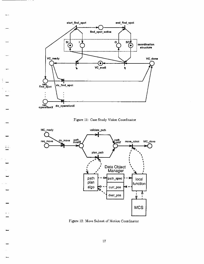
Figure 11 shows an expansion of the Dispatcher find_spot transition to include the coordination structure
and, in this case simple, processing of the command at the Vision Coordinator. The timed find.spot
transition has been modelled by the two instantaneous transitions start_find_.spot and end..find..spot plus
the find..spot_active place.
The coordination structure consists of four places used to control access to the Coordinator. In order
for transition start..find_spot to fire it must acquire the token from the SI input semaphore. It may then
output its request and initiate Coordinator processing by marking the I input place. The marked request
place (or alternatively a PNT tape command may be used) ensures than only one path will be enabled in the
Coordinator. When processing of the request is complete the VC_done place will be marked; and then the
t/ transition restores the input semaphore and returns control to the requesting subnet. Output and output
semaphore places, O and SO respectively, are employed to control this exit. Many Dispatcher transitions
may by connected to a Coordinator PNT but only one at a time will be granted access by virtue of the
coordination structure.
In the study case, find_spot is the only Vision Coordinator service that is required. However, Figure 11
illustrates how additional Vision Coordinator operations would be included. The do_find_spot transition
itself is implemented as a local function call that exchanges messages with the VSS to acquire the requested
z
m
q
m
m
i .
information and then stores it with the DOM as discussed in the next subsection.
Motion Coordinator
The case study requires that the Motion Coordinator service move_robot and find_pos requests from the
Dispatcher. The portion of the Motion Coordinator that performs the move_robot operation is presented
in Figure 12. The coordination structure and expansion of the Dispatcher move_robot transition is not
included.
When a move operation is requested a path may have been previously specified. The Motion Coordinator
is designed to accommodate this preplanned path or to generate a path immediately prior to the move.
Transitions validate_path and plan_path are another example of choice among alternatives that is resolved
through a PNT enabling function (the same function asserted and negated). For the study case the path
must be planned, so transition plan_path will fire. This invokes a call to a path planning algorithm that
retrieves the manipulator's current position and the destination position from the DOM and later stores
the path specification with the DOM. Note that the destination data object was initialized by the earlier
read..next_pos Dispatcher transition. The presence of a valid path specification data object in DOM is
indicated by marking the path_valid place. This marking also enables the move_manlp transition.
Firing the move_manip transition results in a call to a local function that prepares a request message to
MCS. It obtains the input arguments for the MCS message from the DOM. MCS acknowledges completion
of the manipulator move operation to the local function which then updates the current position data object
and completes the move_manlp transition. This example illustrates use of the DOM to exchange data
objects between PNT transition operations, which are separated temporally and distributed among various
processors, and use of PNT places to maintain state information of the existance or validity of data objects
in the DOM.
8 Summary
The computer architecture of an intelligent machine is likely to be heterogeneous and distributed -- re-
flecting the organization of the IM itself. At CIRSSE, the needs of IM researchers have been met through the
development of high-level interfaces (MCS & VSS) to Execution Level hardware, PNT software for affecting
Coordination Level integration, and a means (CTOS) to build distributed applications spanning a heteroge-
neous computing environment. Using these tools the lower two levels of the IM have been implemented, and
the foundation laid for continuation of this work to the IM reasoning functions of the Organization Level.
Acknowledgement
The IM computer architecture at CIRSSE is the product of the efforts of a large number of talented people;
in particular, Kevin Holt, Keith Nicewarner, Russ Noseworthy, Lance Page, Joe Peck, Art Ryan, Sanjeev
Seereeram, Dave Swift, Lee Wilfinger. and the MCS Design Team -- Keith Fieldhouse, Don Lefebvre, Steve
Murphy, and Jim Watson. Funding for this work was provided by NASA under Grant NAGW-1333.
References
[1] J.S. Albus, H.G. McCain and R. Lumia, "NASA/NBS Standard Reference 3/odel for Teler-
obotic Control System Architecture (NASREM)," NIST Tech. Note 1235, National Institute
of Standards and Technology, April 1989.
[2] P. Freedman, "Time, Petri Nets, and Robotics," IEEE Tran. Robotics Automat., vol. 7, no. 4,
pp. 417-435, Aug 1991.
w
10
t
w
L
w
N
m
m
w
[3]
[4]
[5]
[6]
J. Lloyd, M. Parker and R. McClaln, "Extending the RCCL Programming Environment to
Multiple Robots and Processors," Proc. IEEE Int. Conf. Robotics Automat. (Philadelphia,
PA), pp. 465-469, April 1988.
A. Marsan, "Stochastic Petri Nets: An Elementary Introduction," Advances in Petri Nets 1989
(G. Rozenberg, ed.), pp. 1-29, Springer-Verlag, 1989.
M.C. Moed and G.N. Saridis, "A Boltzmann Machine for the Organization of Intelligent Ma-
chines," IEEE Tran. Sys., Man and Cyber. vol. 20, 1990.
T. Murata, "Petri Nets: Properties, Analysis and Applications," Proceedings of the IEEE vol.
77, no. 4, pp. 541-580, 1989.
[7] J.L. Peterson, Petri Net Theory and the Modeling of Systems, Prentice-Hall, 1981.
[8] G.N. Saridis, "Toward the Realization of Intelligent Controls," Proc. IEEE, vol. 67, no. 8, 1979.
[9] G.N. Saridis, "Intelligent Machines: Distributed vs. Hierarchical Intelligence," Proc.
IFA C/IMA C Int. Syrup. on Distrib. Intelligence Systems (Varna, Bulgaria), pp. 34-39, 1988.
[10] G.N. Saridis, "Architectures for Intelligent Machines," CIRSSE Report 96, Rensselaer Poly-
technic Institute, Troy, N.Y., Aug 1991.
[11] G.N. Saridis and J.H. Graham, "Linguistic Decision Schemata for Intelligent Robots," IFAC
J. Automatica, vol. 20, pp. 121-126, 1984.
[12]
[13]
[14]
[i5]
[16]
[17]
[18]
G.N. Saridis and H.E. Stephanou, "A Hierarchical Approach to the Control of A Prosthetic
Arm," IEEE Trans. Sys., Man and Cyber., vol. 7, pp. 407-420, 1977.
G.N. Saridis and K.P. Valavanis, K.P. "Analytical Design of Intelligent Machines," IFAC Y.
Automatica, vol. 24, no. 2, pp. 123-133, 1988.
D.B. Stewart, D.E. Schmitz and P.K. Khosla, "Implementing Real-Time Robotic Systems
Using CHIMERA II," Proc. IEEE Int. Conf. on Robotics Automat. (Cincinnati, Ohio), May1990.
A. Topper, L. Daneshmend and V. Hayward, "A Computing Architecture for a Multiple Robot
Controller - KALI Project," 5th CASI Conf. on Astronautics, Nov. 1988.
F. Wang and G.N. Saridis, "A Coordination Theory for Intelligent Machines," IFAC J. Auto-
matica, vol. 26, pp. 833-844, 1990.
F. Wang and G.N. Saridis, "A Formal Model for Coordination of Intelligent Machines using
Petri Nets," Proc 3rd IEEE Int. InteIl. Control Syrup. (Arlington, VA), 1988.
J.F. Watson, et. al., "Testbed for Cooperative Robotic Manipulators," Intelligent Robotic
Systems For Space Exploration, Kluwer Academic Press, chap. 1, 1991.
w
11
I Organizer I
[ Dispatcher I
oo /onooo"ina'or' ' °oo"inator' ' ' °oor 'inatorsI
Motion Vision
Controller I Con_oller ! ... [ other
controllers
manlpulat°r I I visionhardware J "'" [ otherhardware Inaroware
OrganizationLevel
CoordinationLevel
I ExecutionLevel
w
m
w
m
Figure 1: Logical Model of Intelligent Machine
SunWorkstations
VMECages
Robots &Sensors
OrganlzerJ OrganizationLevel
I Dispatcher
IEthernet
I Motion I I Vision I CoordinationCoordinatorI ICoordinatorl Level
I I1:puO
:pul MotionControl
:pu= System:pu3
:pu4
II 18-DOFrobots
cpu0
=pul VisionServices
DSP, System
IExecution
Level
w
Figure 2: IM Functions Mapped to Testbed Hardware
12
w
i
Organization Level
Coordination Level
CTOS MCS VSS
UNIX
mill i
VxWorks
Figure 3: Software Model of Intelligent Machine
int btsTidSvr (TID_TYPE myTid, MSG_TYPE *msg)
{TASKREC *task ;
TID_TYPE result ;
switch (msg->command/
{case MSG_REGISTER_TID :
/* add rid to symbol table */
task = (TASKREC "1 msg->data ;
symAdd (tidTbl, task->name, _task->tid, 01
return (01 ;
case MSG_QUERY_TID:
/* find rid in symbol table */
if (symYindByName (tidTbl, msg->data, &result,
NULL) == ERROR)
result = 0 ;
msgReply (msg, (void *)result,
MS_KEEP_ADRS, MF_STANDARD) ;
return (0) ;
/* default processing of commands */
return (msgDefaultPro¢ (myTid, msg)) ;
}
Figure 4: Example Event Handler Function
13
-i!

TID_TYPE msgTidQuery (TID_TYPE myTid, char *taskname)
{
MSG_TYPE msg ;
msgBuild (_msg,
TIDSVR,
myTid,
MSG_QUEKY_TID,
taskname,
sizeof(taskname),
MF_REPLYWAIT
);
send message to TID Server */
/, message */
/* dest */
/* source */
/* command */
/* *data */
/* datasize */
I* flags *I
/* return TID in reply message */
return ((TID_TYPE) msgSend (_msg))
}
Figure 5: Example Request to Task
m
w
Application or
StateManager
Client Interface
o
o
Trajectory Generation
Controllers
t slot inte_rface
Channel Drivers
Client InterfaceLayer
Motion PlanningLayer
Motion ControlLayer
Testbed InterfaceLayer
Figure 6: Motion Control System Organization
w
14
w
\ r---,i ..,o,,/ ( 1"°'''"
(power off) (power on)............................ _ _ .............
Figure 7: MCS State Diagram
w
m
i
to
-i-i rr'r"I Service1 I "'" ] Servlcen j
,oo,,i i ,oo,o I
I V','onModu'eM,.nagerJ r
Vision Module lJ " " " IVisl°n Module l
I 'mageF,owor'.er,nterfa°.J
Figure 8: Vision Services System Organization
15

w
I
IpN__
rw t
!rm
l a
_I iBS
CTOS Task
Figure 9: Distributed Petri Net Transducer
w
W
L=
m
L
w
w
move
ca mera_,,,j_It_.ca lib dec_cntr read_next_Dos rob_f_f'_q._po s
_,oo0.......
ro_ _ad-yy _ con,.pos_,,v.,,\\ ,robot .
¢allb_calcs loop_done pos_done pos_found
w Figure 10: Case Study Dispatcher PNT
w
w
16
start_find_spot
find_spot_active
end find spot
0coordination
structure
VC_done
=
r.eq do find_spotflnd_s'_ot
©req do operatlonXoperatTonX -
m
w
Figure 11: Case Study Vision Coordinator
MC_re ady valid atepath
re ore
pfanj_._th
• i
I •
path _i I
plan
algo
Data ObjectManager
"path_spec
curr_pos
dest_pos
move_robot MC_clone,...]1
_.. _-_I •
! t
I t
t t
1 !
• I
!? ,
MCS
Figure 12: Move Subnet of Motion Coordinator
17