a comprehensive approach to in-flisht thrust determination ... · a comprehensive approach to...
TRANSCRIPT

A COMPREHENSIVE APPROACH TO IN-FLISHT THRUST DETERMINATION.(U)FEB 80 P W CHAPIN
UNCLASSIOATCTM-9-33SANL
*E E E E E ",'8mm o m m os

11111 I .0112.0*
H
MICROCO PY RESOLUTION TEST CHARTN AIO t F.LLFAl l0 AL O PI

TM-3 SA
" LEVEL
7ec4tcat ?&mmzaad
A COMPREHENSIVE APPROACH TOIN-FLIGHT THRUST DETERMINATION
Paul W. ChapinAerospace Engineer
Strike Aircraft Test Directorate
15 February 1980 DTICS ELECTEMAR 6 1980.1
B
OF Approved for public release; distribution unlimited.
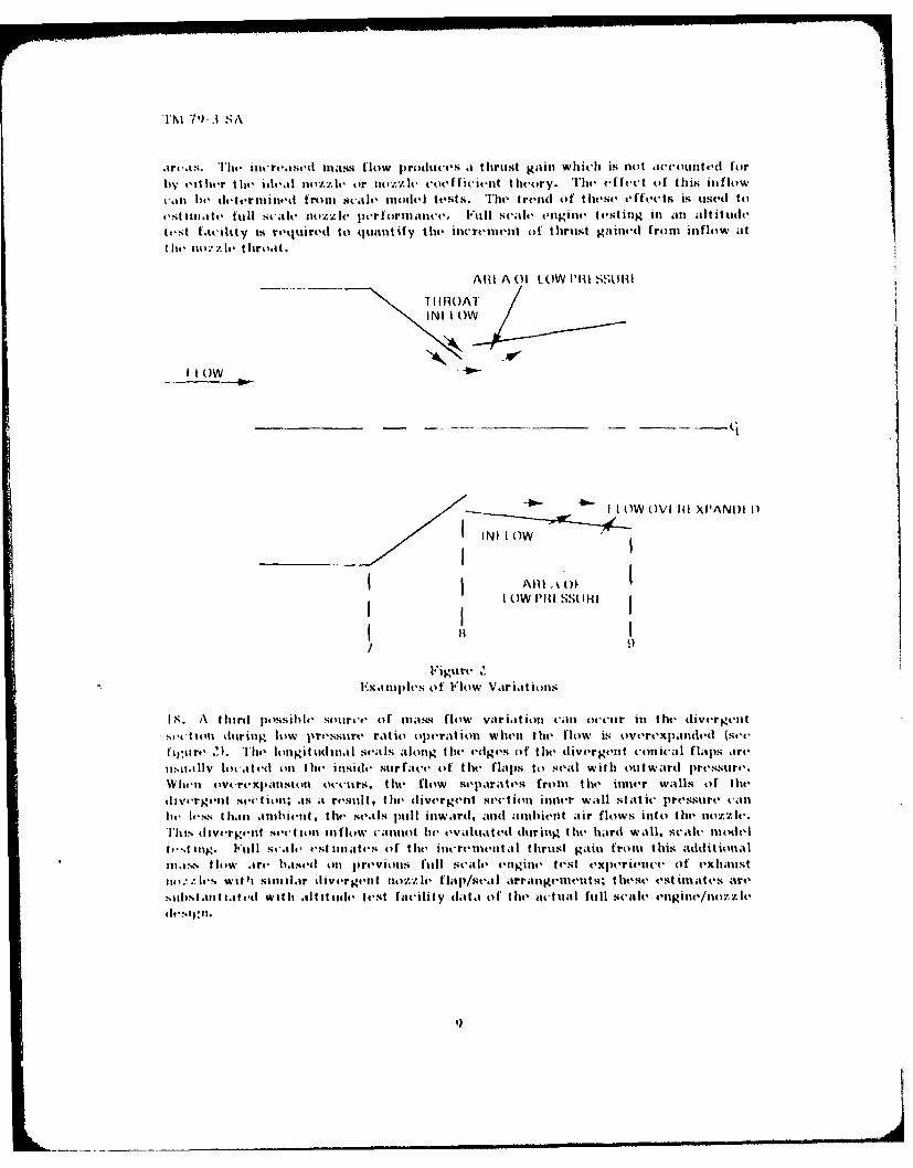
__
NAVAL AIR TEST CENTERTESI PATUXENT RIVER, MARYLAND
I II I IIII I IIII III I I .

UNCLASSIFIEDSECURITY CLASSIFICATION OF THIS PAGE (ibmn Daaa Entoued) READ____ INSTRUCTIONS______
REPORT DOCMENTATION AG BEFORE COMPLETING FORM1REPORT NUMBIER 2. OVT ACCESSION No. 3. RECIPIENT'S CATALOG NUMBER
4TTE(n-61- --- TYPE OF" ED
,COMPREHENSIVE APPROACH TO IN-FLIGHT 9 T CHNICAL MEM
7 AAUTOR(1)S CONTRACT OR GRANT NUMBER(,;)
I *fUL W./CHAPIN
9 P ERFORMING ORGANIZATION NAME AND ADDRESS 10. PROGRAM ELEMENT. PROJECT, TASKAREA a WORK UNIT NUMBERS
STRIKE AIRCRAFT TEST DIRECTORATEPATUXENT RIVER, MARYLAND 20670
I I ' ONTROLLING OFFICE NAME AND ADDRESSI
NAVAL AIR TEST CENTER IA8NAVAL AIR STATION '_MMf.4-&F
PATUXENT RIVER, MARYLAND 20670 22__________4 MONITORING A GENCY NAME A ADORES I different from Controlling Office) 15. SECURITY, CLASS. (of th-s r.-r
C _ UNCLASSIFIEDIS.. OECLASSIFICATION DOWNGRAD~ING
(LIZ SCHEDULE
16. DISTRIBUTION STATEMENT (of this Repot)
APPROVED FOR PUBLIC RELEASE; DISTRIBUTION UNLIMITED.
IS. SUPPLEMENTARY NOTES T r ,
P4MAR 6 1980
19 KEY WORDS (Continua on reverse aidii ifneceeeary and identify by block number)
NET THRUST TEST PLANNING B3GROSS THRUSTRAM DRAGIDEAL NOZZLEEXPANSION EFFICIENCY
20. ABSTRACT (Con rinueotn revere. side if necetaea'ad identify by block number)
t-A systematic, comprehensive approach was used recently to develop an in-flight thrustcomputational routine for a mixed-flow, dual spool, augmented turbofan engine with avariable area convergent-divergent exhaust nozzle. To provide an insight for thenecessity of this approach, a brief historical background of in-flight thrust measurementis presented and classical nozzle theory is discussed briefly. The development of thecomputational routine is discussed and some general test planning guidelines arepresented.
DD I ON. 1473 ILOITION OF 1 NOV 65 IS OBSOLETE 6 ~ UNCLASSIFIED~ 4L/j~ 7~ 0 S RITY CLASSIFICATION OF THIS PAGE (When Date Frt.-I

TM 79-3 SA
PREFACE
The design performance capability of the propulsion system/airframe combinationcan be substantiated without specific knowledge of propulsion system thrust andairframe drag. However, assessment of departures from the design goals requiresthe determination of both airframe drag and propulsion system thrust. Althoughthe ability to determine propulsion system thrust during flight continues to be amain contributor to the uncertainty in evaluating aircraft performance, the Navyhas continually stressed that accurate airframe drag determination necessitatesaccurate in-flight thrust calculations. The development of dynamic performanceflight test techniques has not altered this position. The difficulties in the accuratedetermination of in-flight thrust to a high level of confidence has been attributedto the inadequate application of available technology and a lack of attention todetail. A systematic, comprehensive approach was therefore used recently todevelop an in-flight thrust computational routine utilizing theoretical predictions,modified by model and full scale engine test data. This memorandum discusses thebackground, applicable theory, and approach used in the development of thiscomputational routine and provides some general guidelines relative to in-flightthrust determination.
APPROVED FOR RELEASE
CAPT NE SMITH, USNDirector, Strike Aircraft Test Directorate
_ICESSION for-NTIS White Section
DOC Butt Section 0UAUNNOUNCED rRJSTFICAIDN
WWMNIAVAM.Nf CM~matAVA L or Spec
i I II1

TM 79-3 SA
TABLE OF CONTENTS
Page No.REPORT DOCUMENTATION PAGE i
PREFACE
TABLE OF CONTENTS iii
INTRODUCTION IGENERALBACKGROUND 1
CLASSICAL NOZZLE THEORY 4IDEAL GROSS THRUST 4NOZZLE COEFFICIENTS 6
COMPUTATIONAL ROUTINE DEVELOPMENT 10
TEST PLANNING GUIDELINES 14INTEGRATED PROGRAM PLAN 14SELECTION OF METHOD 15
SUMMARY 16
LIST OF SYMBOLS 17
DISTRIBUTION 18
ill

TM 79-3 SA
INTRODUCTION
GENERAL
1. Various methods for determining in-flight thrust have evolved over the yearsutilizing direct measurement and indirect computational techniques. The directmeasurement technique has generally been regarded as unsatisfactory because theengine should be free from longitudinal constraints. However, this is not practicalwith normal aircraft installations and attempts to account for forces transmittedthrough connectors, supports, and engine-to-airframe seals have not been success-ful. More successful indirect methods have been devised using gross thrust and ramdrag. Various techniques have been developed for computing gross thrust duringflight based on engine and airframe parameters which can be readily measured inflight. A typical approach has been to identify the appropriate ideal situation(based on classical convergent-divergent nozzle and/or classical convergent nozzletheory and a W, Y-or AP nondimc'nsional thrust group), which is then used toestablish an ideal thrust datum. Appropriate calibration factors or coefficients,which identify the efficiency of the expansion process, are then applied to the idealthrust to obtain the actual gross thrust.
Z. This memorandum presents a recent approach taken in the development of anin-flight computational routine for a mixed-flow, dual spool, augmented turbofanengine with a variable area convergent-divergent exhaust nozzle. To provide aninsight for the necessity of the comprehensive approach which was taken, a briefhistorical background of in-flight thrust measurement is first presented. This isfollowed by brief discussions of classical nozzle theory including ideal gross thrustand classical nozzle coefficients used to identify the efficiency of the nozzleexpansion process. Development of the in-flight thrust computational routine isthen discussed and finally some general test planning guidelines are presented.
BACKGROUND
3. The convergent nozzles of early turbojet engines choked at nozzle pressureratios obtainable during sea level static operation. A single gross thrust coeffi-cient (CF) could be established fromh sea level static testing of theairframe/propulsion system on a thrust stand and applied to computed ideal thrustfor extrapolation to the higher nozzle pressure ratios obtained during flight.Figure 1 graphically depicts this procedure. Systematic error on the order of5 percent was generally incurred with this procedure, usually resulting from lack ofadequate identification of power extractions/bleed air variations between the sealevel static testing and actual flight operation. In addition, inaccuracies indetermining the nozzle pressure ratio for some engines contributed to the problem.The ram drag term (which is subtracted from gross thrust to obtain net thrust) wasobtained from uninstalled engine calibrations conducted with a calibratedbellmouth to establish the relationship between mass flow and parametersmeasurable in flight, such as compressor rotor speed and compressor inlettemperature.

TM 79-3 SA
I j--NOZZLE CHOKEDLL
I IDEAL ACTUAL
I-
"" IEXTRAPOLATED
Cn
MEASURED (SLS)
I
1.0 2.0 3.0NOZZLE PRESSURE RATIO
Figure IIn-flight Gross Thrust Determination
Sea Level Test Stand Method
Convergent Nozzle
4. A second procedure which attempted to measure gross thrust and engine massflow involved traversing the nozzle exit plan with a swinging rake apparatus in anattempt to obtain total temperature and total and static pressure maps. Investiga-tions involving turbojet engines indicated random errors of +3 percent and noknown systematic errors. Attempts to apply this procedure to a nonafterburning,convergent nozzle turbofan engine generated doubt as to the validity of themeasurements because of asymmetric pressure profiles and disagreement withthrust stand measurements as high as 7 percent. Tests conducted with afterburningturbofan engines were also unsatisfactory because of large pressure and tempera-ture gradients at the nozzle exit. Other problems associated with this procedureinclude identification of the drag of the swinging rake installation and identifyingthe effect of the installation on airframe/propulsion system interference drag.
2

TM 79-3 SA
5. With the advent of nonafterburning, convergent nozzle, dual spool, mixed-flowturbofan engines, it was found that the nozzle pressure ratio at which the nozzlechoked was not consistent for all flight conditions. It was theorized that theeffective throat area of the core (turbojet) engine varied with flight condition dueto bypass ratio variations and mixing variations which occurred in the nozzlebetween the cooler bypass flow and warmer core engine flow. These problems havebeen less prevalent with afterburning turbofan engines, but problems with accu-rately measuring nozzle throat areas with variable position convergent-divergentnozzles have been encountered. Problems also have been incurred with establishingnozzle pressure ratios based on total pressure measurements made at the lowpressure turbine discharge.
6. In an effort to minimize these problems and reduce uncertainty, the compre-hensive approach described herein was used to develop an in-flight thrust computa-tional routine for a mixed-flow, dual spool, augmented turbofan engine with avariable area convergent-divergent exhaust nozzle.
3
TM 79-3 SA
CLASSICAL NOZZLE THEORY
IDEAL GROSS THRUST
7. Indirect approaches for determining in-flight thrust, or net thrust (FN), arebased on the determination of gross thrust (FG ) and ram drag (FR). Then
F N = FG - FR (1)
where
FG is defined as the sum of momentum and pressure forces at the nozzle
exit
and
FR is defined as the free stream momentum of the mass flow entering the
engine.
Using the above definition, the gross thrust at the nozzle exit plane (station 9) canbe expressed mathematically as
F =WV + A9 (P P (Z)G 9 S9 S0
Nodern turbojet and turbofan engines are required to operate over a wide range ofoperating conditions and, therefore, a wide range of nozzle pressure ratios. Theminimum nozzle pressure ratio which results in sonic flow at the nozzle throat isidentified as the critical pressure ratio. For a convergent-divergent nozzle,operation at pressure ratios below the critical pressure ratio results in overexpan-sion in the divergent sertion of the nozzle while operation at pressure ratios higherthan the critical pressure ratio results in the flow being underexpanded at thenozzle exit plane.
8. For the ideal situation, the flow is assumed to be one-dimensional, theexpansion is assumed to be isentropic, and the specific heat ratio (Y) is usuallyassumed to be constant during the expansion process. Static temperature, velocity,and area (or static pressure) are calculated based on actual (nozzle inlet) totaltemperature, total pressure, and mass flow. When the critical ideal nozzlepressure ratio equals the actual pressure ratio, the ideal static pressure at thenozzle throat (the exit plane for convergent nozzles) is just equal to the free-stream static pressure and the ideal velocity at the throat is Mach 1.0. Duringoperation below the critical ideal nozzle pressure ratio, the static pressure of theflow at the throat equals the free-stream static pressure but the velocity at thethroat will be below Mach 1.0. This "ideal convergent nozzle" concept is applicableto the ideal expansion process and ideal flow calculations for both convergent and
4
i I I I I III I I i l i I II l I II II

TM 79-3 SA
convergent-divergent nozzles operating at or below the ideal critical pressureratio. Above the ideal critical nozzle pressure ratio, an ideal convergent-divergentnozzle concept is used which assumes the flow to be fully expanded to free-streamstatic pressure at the conceptual nozzle exit plan for all operating conditions. Thisidealization leads to an infinitely variable, flexible geometry ideal convergent-divergent nozzle. The ideal gross thrust (FG 9id), computed at this conceptual
nozzle exit plane (where PS9id is equal to PS 0), is the thrust datum against which
actual nozzle thrust is assessed and equation () becomes:
FGgid = W 9(V9)id (3)
where V id is the fully expanded velocity of the internal flow. Using thisconventign, thrust efficiency includes losses both internal and external to theactual nozzle.
9. Other thrust datum conventions may be more convenient for the specificapplication. A fixed-geometry convergent-divergent ideal thrust datum is based ona fixed design point pressure ratio. Departures of actual thrust from the fixed-geometry ideal thrust would then be expressed at other than design pressure ratiosin terms of appropriate coefficients. It is therefore important to have consistentterminology when defining ideal thrust datums so that departures from idealperformance which occur in actual nozzles are identifiable and understood.
10. The form of the mathematical expressions for both ideal convergent and idealconvergent-divergent nozzle gross thrust are predicated on the selection of a"nondimensional ideal thrust group." The selection of a particular group alsodetermines which nozzle coefficients will be used to express the efficiency of theactual expansion process relative to the ideal situation. Two commonly usednondimensional groups are known as the "WVT" and "AP" thrust options and areexpressed mathematically as
___G and FG(4)
t id 0 id
Actually the W/T"group does, in fact, have units and, to be strictly nondimensional,would require the denominator to be W AR-RT. The nondimensional ideal thrustgroup is used to develop expressions which are the bases for calculating ideal flowand ideal thrust. Utilizing the nondimensional group simplifies these calculationsbut mandates using a constant specific heat ratio (Y), which is normally based onthe fuel to air ratio and/or total temperature at the nozzle inlet.
5

TM 79-3 SA
NOZZLE COEFFICIENTS
11. Since gross thrust is defined as the sum of the momentum and pressure forcesat the nozzle exit, it would seem that the most direct approach for determininggross thrust would be to measure the flow conditions at the nozzle exit andcompute gross thrust using these measurements. However, as noted in paragraph 4,attempts to implement this procedure have not been successful. A more acceptedprocedure is to relate nozzle performance to the flow conditions at the nozzle inletand compute ideal gross thrust using the ideal nozzle theory discussed briefly in theprevious section. The assumptions made in the development of this theory neglectthe following salient factors which affect the actual expansion process that occursin a real nozzle:
a. Momentum losses resulting from frictional losses in the nozzle and nonaxialflow at the nozzle exit.
b. Expansion losses resulting trom overexpansion in the nozzle or underexpan-sion at the nozzle exit.
c. Mass flow variations resulting from flow leaking into or out of the nozzle.
Nozzle coefficients have been empirically developed to account for these factorsand are used to obtain actual gross thrust from ideal gross thrust computed for theparticular nozzle inlet conditions.
1Z. The velocity coefficient is a measure of momentum losses expressed mathe-matically as the ratio of the actual to ideal gross thrust expressed in the W/T-nondimensionl group format; the subscript v is used when the ideal group applies tothe ideal convergent-divergent nozzle, and the subscript x is used for the idealconvergent nozzle. Mathematically, the velocity coefficients are expressed as
C FG9act [F0 ]G5Wacttact / idcon-div
C ac t idG(6
- FI(6act tact t id
These definitions can be expanded to more meaningful terms since by definitionideal gross thrust is related to the actual nozzle inlet conditions and
[GF] F0Gi (7)
id t tact
6

TM 79-3 SA
Making this substitution into equation (5), the velocity coefficient becomes theratio of actual to ideal gross thrust for the ideal convergent-divergent nozzle
FG 9
C = 9act (8)Fd
con-div
Defining the velocity at the nozzle exit as
FG9
9 9 act9ef f Wact
then
V9 eff
V V9 idcon-div
where V9 id is that which is obtainable with an ideal flexible convergent-divergentnozzle operating with no mass flow variations (leakage into or out of the nozzle)and with the actual nozzle inlet total pressure and total temperature. Comparingequation (2) with equation (9), the effective and actual velocities at the actualnozzle exit plane are equal only when the actual static pressure at the exit plane(P S is equal to the free-stream static pressure (PS0
13. The flow or discharge coefficient (C ) applies equally to both convergent andconvergent-divergent nozzles and is based~on the nozzle throat area (station 8 for aconvergent-divergent nozzle and for a convergent nozzle station 9 which coincideswith station 8). With no mass flow variation in the nozzle and a given actualnozzle pressure ratio, CD is the ratio of ideal throat area required to pass theactual mass flow to the actual throat area required to pass the flow. For the samenozzle geometry and pressure ratio, it can be shown that the above ratio isequivalent to the ratio of actual to ideal mass flow; hence
A8id W7ctCD = A8act - W7id
7

TM 79-3 SA
14. The gross thrust coefficient is defined as
= F(1)
9act 0 AP (12)
For the convergent nozzle, equation (12) can be simplified so that CG is the
product of the convergent nozzle velocity coefficient (C ) and the dischargecoefficient C D:
CG = D•C (13)
con
For the convergent-divergent nozzle, explicit expressions for the relationshipsbetween CG, CV, and CD vary according to the area used in the FG/APS group.
0In general, these expressions take on the form of equation (13) with CV replacingCX and will include additional area ratio terms.
15. The nozzle coefficients discussed briefly in paragraphs 12, 13, and 14 all arebased on the actual average nozzle inlet conditions, (P , W 7 Tt ), and no
t7 ac 7av av
mass flow variation during the expansion process. However, mass flow variationsfrom W can be expected in the actual nozzle; these variations must be
7actconsidered when estimating full scale nozzle performance and assessing variationsbetween estimated and actual performance. Three types of possible mass flowvariations are discussed below.
16. The exhaust nozzles of high performance turbojet and turbofan engines areusually constructed from sheet metal parts which can be expected to leak. This isparticularly true for the variable area, convergent-divergent nozzle constructedusing longitudinal conical flaps for both the convergent and divergent portions ofthe nozzle; overlapping seals are provided along the longitudinal edges of the flapsto minimize leakage. Estimates of the loss of mass flow through the seals aremade for the full scale nozzle based on previous experience with similar designsand substantiated from full scale engine tests conducted in an altitude test facility.
17. A second possible source of mass flow variation associated with the construc-tion of variable area convergent-divergent nozzles is depicted in figure 2. Thedownstream edge of the convergent conical flaps overlap the upstream edges of thedivergent conical flaps resulting in a sharp corner at the throat. The flowexpanding arourI this sharp corner produces a local area of low static pressure and,as a result, ambient air flows into the nozzle through a gap at the throat betweenthe convergent and divergent flaps. The gap at the throat is required to permitmovement of the convergent and divergent flaps to change the throat and exit
8
TN 1 7) -3 S A
aireas. The~ inc reased mass flow produce's it thrust gain which is not accounte~d forby t'mt her fte ideal no-zz lv or uov. I coe fficilent t heory. The efIfect of this in flowtcanl ho de Icrin ed fromu scale, modelI tests. The t rend of t hese effects is used itoe'st 1111.1te fill[ sce nozzlec per loranlce. Fill scale' engine t est ing in an altitudetest tacility is reqireind to quantify the increment of thrust gamined from inflow atf lit, iio-z I.' throat.
Alit Ao 0l1OW I'MU SSHil
TI I iROATINI I OW
~~ I1OW OVI fit XI'ANII 1)
I N. I O1W
I Alit %'I. Ow l11 SSLIFI
l'igstre ZE*xamiuples of Flow Var iat ions
1S. A third poss1)ic sotirce of mass flow var ia tion call) occtir ini fte dive-rgeitso c tiont dutring tow piressure ratio operation wheni the flow is overexpanded (seet'i:omre .~ The longitt udina seails along fte edges oif thle divergent con icalI flaps arelisoialv located onI the inside suirface of tlihe flaps to seal Witlli oult ward pressure.Wfien ove-rexpaliston occutrs, thet flow se-parates from fte inner walls of ft-di vorget sectin; as at restillt the divergent sect ion intier Wlli static pressure canhe Ivless Iham amhiient , thll seals pill finward, andi anuhient air flows ito thet nozzle.Th is uiverge-iit seclIiont mnflow cannot he evalutated dutrinig the hard Wll,. scale, modeltest log, Fuill scale. est iinates of thet inicremental thrust gaini from this additionalma .ss floi w amre based oni previouas fill scale eniginev test experience of exhaust
ii':sWitlli siman r ivergent nozzle flap/seal arrangemenits; these estimuates are,miafisi ant atet Witlli .nIt ilt ide. test fanci lit y dleit of thet actunal full scale, enlginle/nozzle

TM 79-3 SA
COMPUTATIONAL ROUTINE DEVELOPMENT
19. A systematic, comprehensive approach was used recently to develop an in-flight thrust computational routine for a mixed-flow, dual spool, augmentedturbofan engine with a variable area convergent-divergent exhaust nozzle. Thetest day, test engine net thrust computational routine basically encompassed thefollowing five subroutines:
a. Nozzle inlet total pressure determination based on measured afterburnerinlet total pressure.
b. Nozzle throat area determination.
c. Nozzle coefficient and ideal gross thrust and actual gross thrustdetermination.
d. Actual engine inlet air flow for the determination of ram drag and net
thrust.
e. Afterburner inlet and exit total temperature and specific heat ratio (Y7 )determination.
The first four of these subroutines have provisions to account for engine-to-enginevariations.
Z0. The in-flight computational routine was a contractually required deliverableincluded in the engine development and performance/durability demonstrationprogram. As a result, development of the computational routine was initiatedearly in the engine development program. Predicted engine component and overallengine performance was first established based on theoretical analysis, pastexperience, and gas generator cycle analysis. Model test and component rig testswere conducted to verify and update the performance estimates of the variousengine components. Full scale engine tests were conducted at sea level staticconditions and two Preflight Rating Test (PFRT) engines were tested in an AltitudeTest Facility (ATF). The data base generated from all these tests was used in thedevelopment of the in-flight thrust computational routine. Additional ATF testdata were used to evaluate the effects of changes which occurred between thePFRT and official Qualification Test (QT) engine configurations, and the computa-tional routine was updated as required. To illustrate this comprehensive approach,a detailed discussion of the procedures used to develop the nozzle coefficientfollows.
10

TM 79-3 SA
21. Figure 3 shows schematically the development of each of the pertinentcoefficients applied to the ideal gross thrust to obtain test day gross thrust.Predicted gross thrust was first established based on theoretical analysis, pastexperience, and gas generator cycle analysis. An ideal gross thrust datum wasidentified and used to establish objective thrust coefficient relationships withnozzle pressure ratio for various nozzle throat areas. Cold flow scale model testswere conducted with five fixed position models covering the entire design throat toexit area ratio operating regime and two prospective area ratio schedules. Thesetests established:
a. The variation of the flow coefficient CD with throat area.
b. Momentum losses due to friction and nonaxial flow at the nozzle exitplane.
c. The static pressure distribution over the length of the nozzle.
d. The effect of throat inflow on the gross thrust coefficient (evaluated onone model only).
New gross thrust coefficients were computed using items a and b. Based on thesecalculations, a "model test modifier" was applied to the "objective C ." The modeltests also established that the thrust gain resulting from the inflow at the throatwas greatest at low nozzle pressure ratios where the pressure difference betweenthe throat static pressure and ambient pressure is the greatest.
11

TM 79-3 SA
93U-
00
LUU
0 0
LI LI <I
121

TM 79-3 SA
22. The momentum loss data were then extrapolated to full scale and used with
calculations of ideal exit (V ) and fully expanded (V.o.) velocities (based on the9i li
model test flow coefficient data) to calculate estimated full scale gross thrustcoefficients. Estimates of mass flow variations resulting from leakage, inflow atthe throat, and additional inflow in the divergent section during overexpandedoperation were also included in these full scale estimates. Based on thesecalculations, an "estimated full scale gross thrust modifier" was applied to thepreviously calculated gross thrust coefficient. Based on full scale engine testsconducted in an ATF, an "ATF engine modifier" was computed and used to adjustthe full scale gross thrust coefficient estimates. In addition, the model test flowcoefficient was modified and retained in the actual thrust computation as requiredby the nondimensional thrust group associated with the selected thrust datum. OneATF engine was instrumented to permit accessment of the mass flow inflow in thedivergent section; these data were compared with the full scale estimated data anda modifier applied as required to the final gross thrust computation.
3. This step-by-step, building block procedure was retained in the final in-flightgross thrust computational routine, along with an engine-to-engine gross thrustcoefficiert variation provision, based on uninstalled sea level static test data ofeach particular flight test engine. Each of the solid boxes in figure 3 represents atable lookup in the computer program and each of the lookups can be outputted topermit manual accessment of the values used for the thrust computation.
24. The ATF testing was also used to establish engine airflow relationships,nonafterburning mixing pressure losses, and heat addition pressure losses in theafterburner. The afterburner pressure loss data were required to compute nozzlepressure ratios based on total pressure measured in the inlet of the afterburner.Sixty-three data points from ATF testing of one engine were used to refine thefinal computational routine. Gross thrust of the computational routine wasmatched to the measured thrust within +0.5 percent with an average bias of lessthan 0.1 percent. Airflow was matched to within +0.2 percent with an average biasof less than 0.1 percent. Engine-to-engine variation modifiers were determinedfrom sea level static data of a second engine, and the ATF measured airflow andthrust data from this second engine were compared to computed altitudeperformance. Based on 14 data points, the computational routine predicted higherthan actual gross thrust by 1.5 to 3 percent and predicted airflow to within+0.4 percent with an average bias of 0.2 percent. The net effect of theseinaccuracies on net thrust with +2 percent compared with a predicted uncertaintyin measured net thrust of +1.5 to +2.0 percent. The above discussion exemplifiesthe accuracies currently obtainable when special effort is made to identify detailvariations between theoretical predictions and actual hardware performance.
13

TM 79-3 SA
TEST PLANNING GUIDELINES
INTEGRATED PROGRAM PLAN
Z5. The success achieved from a test program is directly related to the degree ofattention given to details early in the planning phase of the overall developmentprogram. Early involvement of both propulsion system ground test specialist andflight test specialist will enhance the potential for successfully meeting the desiredground and flight test goals. General test program goals, applicable to both theground and flight test programs, are:
a. To substantiate that the design performance capabilities of the propulsionsystem and propulsion system/airframe combination have been met.
b. To provide information for assessment of departures from design goals andidentify the causes of depar4 ures.
c. To provide information which will permit accurate prediction of perform-ance variations resulting from design changes which occur during theoperational life cycle of the airframe and propulsion system.
d. To provide information which can be feedback to the designer and used tosubstantiate and enhance theoretical estimation techniques.
e. To provide a data base for improvement of future designs.
The test programs, data acquisition systems, and data reduction procedures mustbe structured to meet these goals. A successful approach for achieving thisrequirement has been the use of a task force concept involving all the variousspecialists involved with the development, test, and evaluation of both thepropulsion system and the airframe/propulsion system combination. Formation ofthe task force should be accomplished to insure proper integration of the following:
f. Model, rig, and full scale propulsion system test programs.
g. Airframe wind tunnel test programs.
h. Selection of airframe and propulsion system test instrumentation.
i. Selection of the in-flight thrust computational method.
j. Data handling procedures used for both the propulsion system ground testsand airframe/propulsion system flight tests.
An integrated planned approach should be formulated by the task force andresponsibilities assigned for prosecution of the plan. Periodic meetings of the taskforce should be held to review progress and update the plan as required.
14

TM 79-3 SA
SELECTION OF METHOD
Z6. Selection of a method for computing in-flight thrust is made predicted on theparticular circumstances of the specific program. Factors which should beconsidered in this selection are:
a. The scope and nature of the flight test program as dictated by theapplicable flight test goals.
b. The known state-of-the-art accuracies obtainable from each of the candi-date methods as applied to the type of propulsion system (turbojet orturbofan and nozzle type).
c. The economics of the particular situation as dictated by availableresources relative to desired test goals.
Z7. The goals of the flight test program are a predominant factor which willinfluence the selection of a method for computing in-flight thrust. It is paramountthat these goals be firmly established prior to any attempt to select an in-flightthrust computational method. Predicted design performance capability of thepropulsion system/airframe combination is made based on drag estimates of theairframe and propulsion system thrust estimates. The design performance capa-bility of the propulsion system/airframe combination can be substantiated withoutspecific knowledge of propulsion system thrust and airframe drag. However, if thegoal of the flight test program is to provide information for explicit assessment ofdepartures from the design goals, then an in-flight thrust computational methodwhich will provide accurate in-flight thrust information is required. The costinvolved with utilization of one particular in-flight method compared to anothermethod must be weighted against the fidelity of the data obtainable from each ofthe methods and related to the explicitness of the desired departure assessment.Similarly, the necessity for providing high fidelity information for enhancement oftheoretical estimation techniques, and the size and quality of the data base to begenerated for assessment of design changes and improvement of future designs,must be considered along with available resources in the selection of an in-flightthrust computational method.
15

TM 79-3 SA
SUMMARY
28. Several recent development programs have demonstrated that reasonablyaccurate in-flight thrust can be determined from the flight test data. Theuncertainty associated with in-flight thrust calculations has been minimized usingexisting technology and carefully applying detailed analysis and procedures toidentify the causes for variations between predicted and actual propulsion systemperformance. The key to the success of these programs has been attributed to thecare taken during development of the in-flight thrust computational routine withemphasis placed on attention to details and a thorough understanding of theexhaust nozzle expansion process.
Z9. The information presented herein is provided to acquaint the flight testproject engineer with a general understanding and appreciation for:
a. The historical background of the in-flight thrust determination problem.
b. Classical nozzle theory including ideal gross thrust and classical nozzlecoefficients.
c. An example of a comprehensive approach used recently to develop an in-flight thrust computational routine starting with theoretical predictions,which were first modified by model test results (adjust to full scale) andthen by full scale ATF engine test data.
d. The approach used to plan and implement development of in-flight compu-tational routines for several recent successful full scale developmentprograms.
16
TM 79-3 SA
LIST OF SYMBOLS
A Area
CD 'Flow or Discharge Coefficient
C G Gross Thrust Coefficient
CF Ratio Measured to Ideal Gross Thrust
C V Velocity Coefficient for Ideal Convergent-Divergent Nozzle
C X Velocity Coefficient for Ideal Convergent Nozzle
FG Gross ThrustGs
FN Net Thrust
FR Ram Drag
NPR Nozzle Pressure Ratio (P T /P0
P Pressure
R Gas Constant
T Temperature
V Velocity
W Mass Flow
Y Specific Heat Ratio
Subscripts Nozzle Station Notation
act actual 0 Free stream
av average 7 Nozzle inlet
con convergent 8 Nozzle throat
con-div convergent-divergent 9 Nozzle exit
eff effective
id ideal
S static
t total
17

TM 79-3 SA
DISTRIBUTION:
NAVAIRSYSCOM (AIR-530121) (3)NAVAIRTESTCEN (SA04) (3)NAVAIRTE8TCEN (SA6O) (30)NAVAIRTESTCEN (AT63) (5)NAVA1RTESTCEN (TP4O) (5)DTIC (1 Z)

I