a comparative study for dimensioning of ... comparative study for dimensioning of footings 1317...
TRANSCRIPT

International Journal of InnovativeComputing, Information and Control ICIC International c©2014 ISSN 1349-4198Volume 10, Number 4, August 2014 pp. 1313–1326
A COMPARATIVE STUDY FOR DIMENSIONING OF FOOTINGSWITH RESPECT TO THE CONTACT SURFACE ON SOIL
Arnulfo Luevanos Rojas
Facultad de Ingenieria, Ciencias y ArquitecturaUniversidad Juarez del Estado de Durango
Av. Universidad S/N, Fracc. Filadelfia, CP 35010, Gomez Palacio, Durango, Mexicoarnulfol [email protected]
Received August 2013; revised December 2013
Abstract. This paper presents a comparative study among three types of footings ofdifferent shape to obtain the more economical dimension of the contact surface, i.e.,a comparison is realized among the rectangular footings, square and circular in termsof the contact area with soil, when load that must withstand said structural member isapplied. The models presented in this paper satisfy the following conditions. 1) Theminimum stress should be equal to or greater than zero, because the soil is not capable ofwithstanding tensile stresses. 2) The maximum stress must be equal to or less than theallowable capacity that can be capable of withstanding the soil. According to the results,tables show that the circular footings are more economic, subsequently the rectangularfootings and last the square footings.Keywords: Circular footings, Rectangular footings, Square footings, Allowable capacityof soil, Contact surface, More economical dimension
1. Introduction. The foundation is the part of the structure which transmits the loadsto the floor. Each building demands the need to solve a problem of foundation. Thefoundations are classified into superficial and deep, which have important differences: interms of geometry, the behavior of the soil, its structural functionality and its constructivesystems [1,2].
A superficial foundation is a structural member whose cross section is of large dimen-sions with respect to height and whose function is to transfer the loads of a buildingat depths relatively short, less than 4 m approximately with respect to the level of thenatural ground surface [3,4].
Superficial foundations, whose constructive systems generally do not present majordifficulties, may be of various types according to their function; isolated footing, combinedfooting: strip footing, or mat foundation [5].
In the design of superficial foundations, the specific cases of isolated footings are ofthree types in terms of the application of the loads. 1) Footings subject to concentricaxial load. 2) Footings subject to axial load and moment in one direction (unidirectionalbending). 3) Footings subject to axial load and moment in two directions (bidirectionalbending) [1-4].
The hypothesis used in the classical model is developed by trial and error, i.e., a di-mension is proposed, and last the expression of the bidirectional bending is used to obtainthe stress acting on the contact surface of footings, which must satisfy the following con-ditions. 1) The minimum stress should be equal to or greater than zero, because the soilis not capable of withstanding tensile stresses. 2) The maximum stress must be equal toor less than the allowable capacity that can withstand the soil [1-5].
1313
1314 A. LUEVANOS ROJAS
Lately, a mathematical model is developed to take into account the real pressure ofsoil acting on the contact surface of the rectangular footing when applying the load thatmust support said structural member [6]. Also a full mathematical model is presentedfor design of rectangular footings to obtain: 1) the moment around of an axis a’-a’ thatis parallel to axis “X-X” and moment around an axis b’-b’ that is parallel to axis “Y-Y”; 2) the shear forces by bending (unidirectional shear force); 3) the shear forces bypenetration (bidirectional shear force) for footings that are supporting to a rectangularcolumn or a circular column for footings subject to axial load and moment in two directions(bidirectional bending) [7].In recent years, mathematical models have been developed to obtain the more econom-
ical dimension of rectangular footings, square and circular subjected to an axial load andmoments in two directions (bidirectional bending) that comply with the aforementionedconditions [8-10].This paper presents a comparative study between three types of footings to obtain the
more economical dimension of the contact surface, i.e., a comparison is realized amongthe rectangular footings, square and circular subjected to axial load and moment in twodirections (bidirectional bending), in terms of the contact area on soil, when load that mustwithstand said structural member is applied, where there are two conditions that mustsatisfy: the first condition is that the minimum stress should be equal to or greater thanzero, because the soil is not able to withstand tensile stresses, and the second conditionis that the maximum stress should be equal to or less than the allowable capacity of thesoil. Also, each model presents the point where maximum stress and minimum appear.
2. Mathematical Development of the Models.
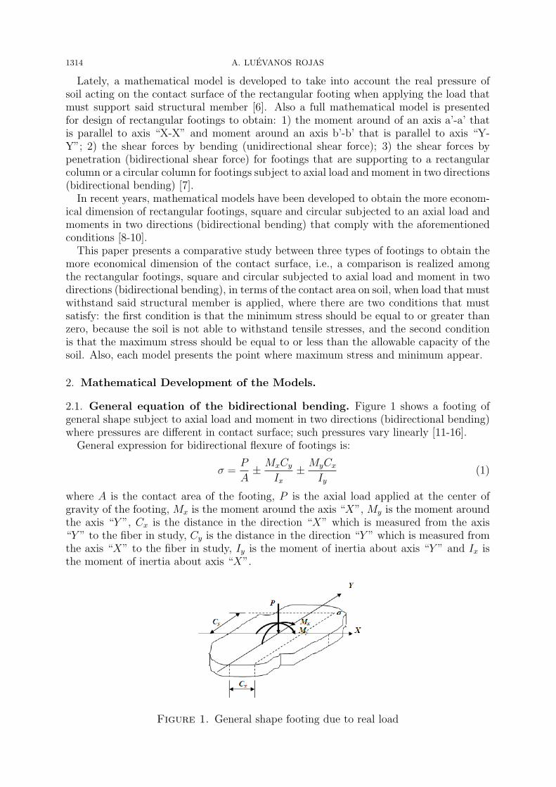
2.1. General equation of the bidirectional bending. Figure 1 shows a footing ofgeneral shape subject to axial load and moment in two directions (bidirectional bending)where pressures are different in contact surface; such pressures vary linearly [11-16].General expression for bidirectional flexure of footings is:
σ =P
A± MxCy
Ix± MyCx
Iy(1)
where A is the contact area of the footing, P is the axial load applied at the center ofgravity of the footing, Mx is the moment around the axis “X”, My is the moment aroundthe axis “Y ”, Cx is the distance in the direction “X” which is measured from the axis“Y ” to the fiber in study, Cy is the distance in the direction “Y ” which is measured fromthe axis “X” to the fiber in study, Iy is the moment of inertia about axis “Y ” and Ix isthe moment of inertia about axis “X”.
Figure 1. General shape footing due to real load

A COMPARATIVE STUDY FOR DIMENSIONING OF FOOTINGS 1315
Any type of footings must satisfy the following conditions: the first condition is thatthe minimum stress should be equal to or greater than zero, because the soil is not ableto withstand tensile stresses; the second condition is that the maximum stress should beequal to or less than the allowable capacity of the soil.
2.2. Rectangular footing. Figure 2 shows a rectangular footing due to a real loadsubjected to an axial load and moment in two directions (bidirectional bending) wherepressures are different in the four corners of the contact surface [8,11-16].
Figure 2. Rectangular footing due to real load
Geometric properties for rectangular footings are: A = bh, Cy = h/2, Cx = b/2,Ix = bh3/12 and Iy = hb3/12, which are substituted into Equation (1) to find the stressesat each corner of rectangular footings:
σ1 =P
bh+
6Mx
bh2+
6My
b2h(2)
σ2 =P
bh+
6Mx
bh2− 6My
b2h(3)
σ3 =P
bh− 6Mx
bh2+
6My
b2h(4)
σ4 =P
bh− 6Mx
bh2− 6My
b2h(5)
where σ1 = σmax is the maximum stress and σ4 = σmin is the minimum stress.For a rectangular footing there are two conditions: the first is that the minimum stress
should be zero, since the soil is not capable of withstanding tensile stresses and the secondis that the maximum stress is the load capacity that can withstand the soil.
2.2.1. General conditions. Figure 3 presents a rectangular footing rectangular due toequivalent load. The normal solicitations of components are P , Mx, My, which are equiv-alent to an axial force P acting in the point action with coordinates (ex, ey).
The permitted maximum eccentricity that the tensile stresses are not presented in thesoil is 1/6 the side of the footing. Then the eccentricity is defined as follows [8,11-15]:
ex =My
P=
b
6→ P =
6My
b(6)
ey =Mx
P=
b
6→ P =
6Mx
h(7)
where ex is the eccentricity in the direction “X”, and ey is the eccentricity in the direction“Y ”.

1316 A. LUEVANOS ROJAS
Figure 3. Rectangular footing due to equivalent load
The values of P are equal in Equations (6) and (7):
6My
b=
6Mx
h(8)
The value b is found from Equation (8):
b =Myh
Mx
(9)
2.2.2. First condition. The minimum stress is zero:
σmin = σ4 = 0 (10)
Equation (10) is substituted into Equation (5):
0 =P
bh− 6Mx
bh2− 6My
b2h(11)
Equation (11) is presented as follows:
0 = Pbh− 6Mxb− 6Myh (12)
Equation (9) is substituted into Equation (12), and we have the following:
0 = P
(Myh
Mx
)h− 6Mx
(Myh
Mx
)− 6Myh (13)
Equation (13) is simplified:
0 = Ph− 6Mx − 6Mx (14)
Then of Equation (14) is found “h” as follows:
h =12Mx
P(15)
When Equation (15) is substituted into Equation (9), “b” is obtained:
b =12My
P(16)
Therefore, of Equations (15) and (16) are found the dimensions of a rectangular footing,when the pressure of soil on the footing is zero.
A COMPARATIVE STUDY FOR DIMENSIONING OF FOOTINGS 1317
2.2.3. Second condition. The maximum stress is the loading capacity of the soil:
σ1 = σmax (17)
Equation (17) is substituted into Equation (2):
σmax =P
bh+
6Mx
bh2+
6My
b2h(18)
Equation (18) is presented as follows:
σmaxb2h2 = Pbh+ 6Mxb+ 6Myh (19)
Equation (9) is substituted into Equation (19) as the following:
σmax
(Myh
Mx
)2
h2 = P
(Myh
Mx
)h+ 6Mx
(Myh
Mx
)+ 6Myh (20)
Equation (20) is simplified:
σmaxMyh3 − PMxh− 12M2
x = 0 (21)
Then of Equation (21) is solved to obtain value “h”, and this is substituted into Equa-tion (9) to find the value “b”. These are dimensions of a rectangular footing when thepressure is the loading capacity of the soil.
Therefore, the proposal minimum dimension of a rectangular footing is the following:the dimension greater obtained the first condition by Equations (15) and (16) or thesecond condition by Equations (9) and (21).
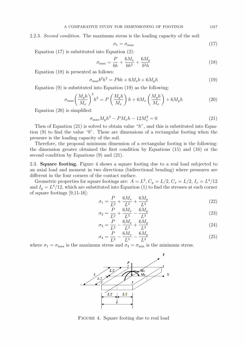
2.3. Square footing. Figure 4 shows a square footing due to a real load subjected toan axial load and moment in two directions (bidirectional bending) where pressures aredifferent in the four corners of the contact surface.
Geometric properties for square footings are: A = L2, Cy = L/2, Cx = L/2, Ix = L4/12and Iy = L4/12, which are substituted into Equation (1) to find the stresses at each cornerof square footings [9,11-16]:
σ1 =P
L2+
6Mx
L3+
6My
L3(22)
σ2 =P
L2+
6Mx
L3− 6My
L3(23)
σ3 =P
L2− 6Mx
L3+
6My
L3(24)
σ4 =P
L2− 6Mx
L3− 6My
L3(25)
where σ1 = σmax is the maximum stress and σ4 = σmin is the minimum stress.
Figure 4. Square footing due to real load
1318 A. LUEVANOS ROJAS
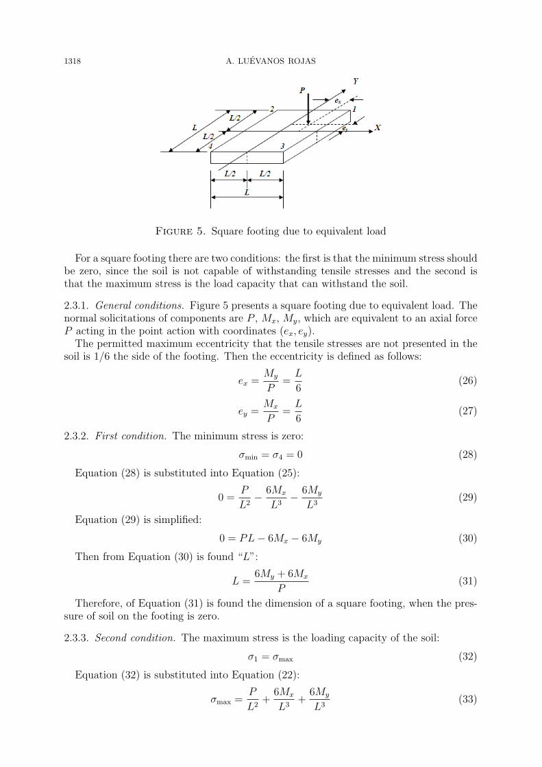
Figure 5. Square footing due to equivalent load
For a square footing there are two conditions: the first is that the minimum stress shouldbe zero, since the soil is not capable of withstanding tensile stresses and the second isthat the maximum stress is the load capacity that can withstand the soil.
2.3.1. General conditions. Figure 5 presents a square footing due to equivalent load. Thenormal solicitations of components are P , Mx, My, which are equivalent to an axial forceP acting in the point action with coordinates (ex, ey).The permitted maximum eccentricity that the tensile stresses are not presented in the
soil is 1/6 the side of the footing. Then the eccentricity is defined as follows:
ex =My
P=
L
6(26)
ey =Mx
P=
L
6(27)
2.3.2. First condition. The minimum stress is zero:
σmin = σ4 = 0 (28)
Equation (28) is substituted into Equation (25):
0 =P
L2− 6Mx
L3− 6My
L3(29)
Equation (29) is simplified:
0 = PL− 6Mx − 6My (30)
Then from Equation (30) is found “L”:
L =6My + 6Mx
P(31)
Therefore, of Equation (31) is found the dimension of a square footing, when the pres-sure of soil on the footing is zero.
2.3.3. Second condition. The maximum stress is the loading capacity of the soil:
σ1 = σmax (32)
Equation (32) is substituted into Equation (22):
σmax =P
L2+
6Mx
L3+
6My
L3(33)

A COMPARATIVE STUDY FOR DIMENSIONING OF FOOTINGS 1319
Equation (33) is presented as follows:
σmaxL3 − PL− 6(Mx +My) = 0 (34)
Then of Equation (34) is solved to obtain value “L”, and this is the dimension of asquare footing when the pressure is the loading capacity of the soil.
Therefore, the proposal minimum dimension of a square footing is the following: thedimension greater obtained the first condition by Equation (31) or the second conditionby Equation (34).
2.4. Circular footing. Figure 6 shows a circular footing due to a real load subjected toan axial load and moment in two directions (bidirectional bending) where pressures aredifferent in the entire contact surface.
2.4.1. General conditions. Figure 7 presents a typical circular footing to obtain the stress-es in any point on the contact surface of said structural member due to pressure exertedby the soil.
Geometric properties for circular footings are: A = πd2/4, Cy = y, Cx = x, Ix = d4/64and Iy = d4/64, which are substituted into Equation (1) to find the stresses on the contactsurface of circular footings [9,11-16]:
σ(x, y) =4P
πd2+
64Mxy
πd4+
64Myx
πd4(35)
Figure 6. Circular footing due to real load
Figure 7. Circular footing in plan
1320 A. LUEVANOS ROJAS
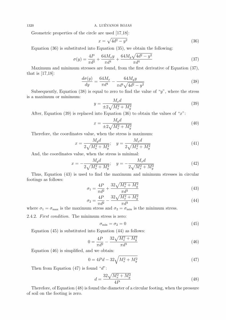
Geometric properties of the circle are used [17,18]:
x =√4d2 − y2 (36)
Equation (36) is substituted into Equation (35), we obtain the following:
σ(y) =4P
πd2+
64Mxy
πd4+
64My
√4d2 − y2
πd4(37)
Maximum and minimum stresses are found, from the first derivative of Equation (37),that is [17,18]:
dσ(y)
dy=
64Mx
πd4− 64Myy
πd4√
4d2 − y2(38)
Subsequently, Equation (38) is equal to zero to find the value of “y”, where the stressis a maximum or minimum:
y =Mxd
±2√M2
x +M2y
(39)
After, Equation (39) is replaced into Equation (36) to obtain the values of “x”:
x =Myd
±2√
M2x +M2
y
(40)
Therefore, the coordinates value, when the stress is maximum:
x =Myd
2√
M2x +M2
y
; y =Mxd
2√M2
x +M2y
(41)
And, the coordinates value, when the stress is minimal:
x = − Myd
2√
M2x +M2
y
; y = − Mxd
2√
M2x +M2
y
(42)
Thus, Equation (43) is used to find the maximum and minimum stresses in circularfootings as follows:
σ1 =4P
πd2+
32√
M2x +M2
y
πd3(43)
σ2 =4P
πd2−
32√
M2x +M2
y
πd3(44)
where σ1 = σmax is the maximum stress and σ2 = σmin is the minimum stress.
2.4.2. First condition. The minimum stress is zero:
σmin = σ2 = 0 (45)
Equation (45) is substituted into Equation (44) as follows:
0 =4P
πd2−
32√
M2x +M2
y
πd3(46)
Equation (46) is simplified, and we obtain:
0 = 4Pd− 32√
M2x +M2
y (47)
Then from Equation (47) is found “d”:
d =32√M2
x +M2y
4P(48)
Therefore, of Equation (48) is found the diameter of a circular footing, when the pressureof soil on the footing is zero.

A COMPARATIVE STUDY FOR DIMENSIONING OF FOOTINGS 1321
2.4.3. Second condition. The maximum stress is the loading capacity of the soil:
σ1 = σmax (49)
Equation (49) is substituted into Equation (43) as follows:
σmax =4P
πd2+
32√M2
x +M2y
πd3(50)
Equation (50) is simplified, and we obtain:
σmaxπd3 − 4Pd− 32
√M2
x +M2y = 0 (51)
Then of Equation (51) is solved to obtain value “d”, and this is the dimension of acircular footing when the pressure is the loading capacity of the soil.
Therefore, the proposal minimum diameter of a circular footing is the following: thedimension greater obtained the first condition by Equation (48) or the second conditionby Equation (51).
3. Application. An example is presented for rectangular footings, square and circularsubjected to an axial load and moment in two directions (bidirectional bending) to showthe differences.
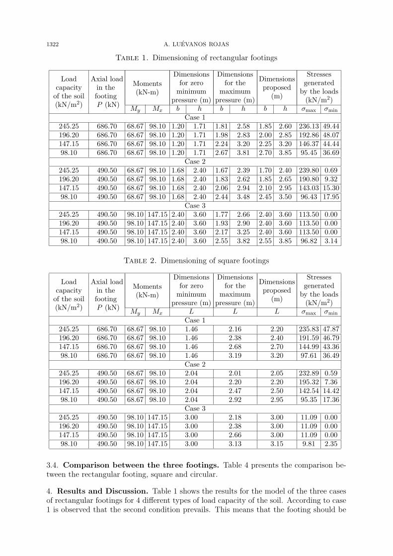
3.1. Rectangular footing. Below, the three cases of rectangular footings are presented.The dimensions are obtained by means of Equations (15) and (16), when the minimumpressure is zero. The dimensions are found by means of Equations (9) and (21), where themaximum pressure is the soil loading capacity. The proposed dimensions are found takinginto account the larger of the two above conditions. Once the dimensions of the footingare defined, the stresses generated by loads applied to the foundation are obtained toverify that these stresses are within the established parameters, i.e., the maximum stressis equal to or less than the load capacity of the soil, and the minimum stress is equal toor greater than zero, since the soil is not capable of withstanding the tensile stresses. Theresults are presented in Table 1.
3.2. Square footing. Below, the three cases of square footings are presented. The di-mension is found through Equation (31), when the minimum pressure is zero. The dimen-sion is obtained through Equation (34), where the maximum pressure is the soil loadingcapacity. The proposed dimension is found taking into account the larger of the twoabove conditions. Once the dimension of the footing is defined, the stresses generated byloads applied to the foundation are obtained to verify that these stresses are within theestablished parameters, i.e., the maximum stress is equal to or less than the load capacityof the soil, and the minimum stress is equal to or greater than zero, since the soil is notcapable of withstanding the tensile stresses. The results are presented in Table 2.
3.3. Circular footing. Below, the three cases of circular footings are presented. Thediameter is obtained through Equation (48), when the minimum pressure is zero. Thediameter is found through Equation (51), where the maximum pressure is the soil loadingcapacity. The proposed diameter is found taking into account the larger of the two aboveconditions. Once the diameter of the footing is defined, the stresses generated by loadsapplied to the foundation are found to verify that these stresses are within the establishedparameters, i.e., the maximum stress is equal to or less than the load capacity of the soil,and the minimum stress is equal to or greater than zero, since the soil is not capable ofwithstanding the tensile stresses. The results are presented in Table 3.
1322 A. LUEVANOS ROJAS
Table 1. Dimensioning of rectangular footings
Load Axial loadMoments
Dimensions DimensionsDimensions
Stresses
capacity in the(kN-m)
for zero for theproposed
generated
of the soil footingminimum maximum
(m)by the loads
(kN/m2) P (kN)pressure (m) pressure (m) (kN/m2)
My Mx b h b h b h σmax σmin
Case 1245.25 686.70 68.67 98.10 1.20 1.71 1.81 2.58 1.85 2.60 236.13 49.44196.20 686.70 68.67 98.10 1.20 1.71 1.98 2.83 2.00 2.85 192.86 48.07147.15 686.70 68.67 98.10 1.20 1.71 2.24 3.20 2.25 3.20 146.37 44.4498.10 686.70 68.67 98.10 1.20 1.71 2.67 3.81 2.70 3.85 95.45 36.69
Case 2245.25 490.50 68.67 98.10 1.68 2.40 1.67 2.39 1.70 2.40 239.80 0.69196.20 490.50 68.67 98.10 1.68 2.40 1.83 2.62 1.85 2.65 190.80 9.32147.15 490.50 68.67 98.10 1.68 2.40 2.06 2.94 2.10 2.95 143.03 15.3098.10 490.50 68.67 98.10 1.68 2.40 2.44 3.48 2.45 3.50 96.43 17.95
Case 3245.25 490.50 98.10 147.15 2.40 3.60 1.77 2.66 2.40 3.60 113.50 0.00196.20 490.50 98.10 147.15 2.40 3.60 1.93 2.90 2.40 3.60 113.50 0.00147.15 490.50 98.10 147.15 2.40 3.60 2.17 3.25 2.40 3.60 113.50 0.0098.10 490.50 98.10 147.15 2.40 3.60 2.55 3.82 2.55 3.85 96.82 3.14
Table 2. Dimensioning of square footings
Load Axial loadMoments
Dimensions DimensionsDimensions
Stresses
capacity in the(kN-m)
for zero for theproposed
generated
of the soil footingminimum maximum
(m)by the loads
(kN/m2) P (kN)pressure (m) pressure (m) (kN/m2)
My Mx L L L σmax σmin
Case 1245.25 686.70 68.67 98.10 1.46 2.16 2.20 235.83 47.87196.20 686.70 68.67 98.10 1.46 2.38 2.40 191.59 46.79147.15 686.70 68.67 98.10 1.46 2.68 2.70 144.99 43.3698.10 686.70 68.67 98.10 1.46 3.19 3.20 97.61 36.49
Case 2245.25 490.50 68.67 98.10 2.04 2.01 2.05 232.89 0.59196.20 490.50 68.67 98.10 2.04 2.20 2.20 195.32 7.36147.15 490.50 68.67 98.10 2.04 2.47 2.50 142.54 14.4298.10 490.50 68.67 98.10 2.04 2.92 2.95 95.35 17.36
Case 3245.25 490.50 98.10 147.15 3.00 2.18 3.00 11.09 0.00196.20 490.50 98.10 147.15 3.00 2.38 3.00 11.09 0.00147.15 490.50 98.10 147.15 3.00 2.66 3.00 11.09 0.0098.10 490.50 98.10 147.15 3.00 3.13 3.15 9.81 2.35
3.4. Comparison between the three footings. Table 4 presents the comparison be-tween the rectangular footing, square and circular.
4. Results and Discussion. Table 1 shows the results for the model of the three casesof rectangular footings for 4 different types of load capacity of the soil. According to case1 is observed that the second condition prevails. This means that the footing should be

A COMPARATIVE STUDY FOR DIMENSIONING OF FOOTINGS 1323
Table 3. Dimensioning of circular footings
Load Axial loadMoments
Dimensions DimensionsDimensions
Stresses
capacity in the(kN-m)
for zero for theproposed
generated
of the soil footingminimum maximum
(m)by the loads
(kN/m2) P (kN)pressure (m) pressure (m) (kN/m2)
My Mx d d d σmax σmin
Case 1245.25 686.70 68.67 98.10 1.40 2.38 2.40 240.05 63.57196.20 686.70 68.67 98.10 1.40 2.61 2.65 190.02 58.96147.15 686.70 68.67 98.10 1.40 2.96 3.00 142.34 51.9998.10 686.70 68.67 98.10 1.40 3.53 3.55 96.63 42.08
Case 2245.25 490.50 68.67 98.10 1.95 2.19 2.20 243.58 14.52196.20 490.50 68.67 98.10 1.95 2.40 2.45 186.98 21.09147.15 490.50 68.67 98.10 1.95 2.70 2.75 141.26 23.9498.10 490.50 68.67 98.10 1.95 3.20 3.25 94.67 23.64
Case 3245.25 490.50 98.10 147.15 2.88 2.37 2.90 148.13 0.39196.20 490.50 98.10 147.15 2.88 2.59 2.90 148.13 0.39147.15 490.50 98.10 147.15 2.88 2.91 2.95 141.95 1.5798.10 490.50 98.10 147.15 2.88 3.42 3.45 96.33 8.63
dimensioned on the basis of load capacity of the soil. As regards the case 2, also thesecond condition is dominant. Finally, we analyze the case 3, in which the first threetypes of load capacities of the soil are dominant to the first condition. This means thatthe footing should be dimensioned on the basis of the minimum pressure where this iszero, because the soil cannot support tensile stresses. The fourth type is dominant in thiscase to the second condition.
Table 2 presents the results for the model of the three cases of square footings for 4different types of load capacity of the soil. According to case 1 shows that the secondcondition is dominant. This means that the footing should be dimensioned on the basis ofload capacity of the soil. As regards the case 2, also the second condition prevails with theexception of the first type which is dominant to the first condition. Finally, we analyzethe case 3, in which the first three types of load capacities of the soil are dominant tothe first condition. This means that the footing should be dimensioned on the basis ofthe minimum pressure where this is zero, because the soil cannot support tensile stresses.The fourth type is dominant in this case to the second condition.
Table 3 shows the results for the model of the three cases of circular footings for 4different types of load capacity of the soil. According to case 1 shows that the secondcondition prevails. This means that the footing should be dimensioned on the basis ofload capacity of the soil. As regards the case 2, also the second condition is dominant.Finally, we analyze case 3, in which the first two types of load capacities of the soil aredominant the first condition. This means that the footing should be dimensioned on thebasis of the minimum pressure where this is zero, because the soil cannot support tensilestresses. The third type and fourth are dominant in this case to the second condition.
Table 4 presents the comparison among the rectangular footing, square and circular.According to the results tables show that the circular footings are more economic, subse-quently the rectangular footings and last the square footings. Hence, the comparison ismade between the square and rectangular footings with respect to the circular footings.

1324 A. LUEVANOS ROJAS
Table 4. Comparison of results between the three types of footings
Load Axial loadMoments
Dimensions Dimensions DimensionsComparison
capacity in the(kN-m)
of of ofof
of the soil footingrectangular square circular
results(kN/m2) P (ton)
footings footings footingsMy Mx b (m) h (m) A (m2) L (m) A (m2) d (m) A (m2) RF/CF SF/CF
Case 1245.25 686.70 68.67 98.10 1.85 2.60 4.81 2.20 4.84 2.40 4.52 1.064 1.071196.20 686.70 68.67 98.10 2.00 2.85 5.70 2.40 5.76 2.65 5.52 1.033 1.043147.15 686.70 68.67 98.10 2.25 3.20 7.20 2.70 7.29 3.00 7.07 1.018 1.03198.10 686.70 68.67 98.10 2.70 3.85 10.40 3.20 10.24 3.55 9.90 1.051 1.034
Case 2245.25 490.50 68.67 98.10 1.70 2.40 4.08 2.05 4.20 2.20 3.80 1.074 1.105196.20 490.50 68.67 98.10 1.85 2.65 4.90 2.20 4.84 2.40 4.52 1.084 1.071147.15 490.50 68.67 98.10 2.10 2.95 6.20 2.50 6.25 2.70 5.73 1.082 1.09198.10 490.50 68.67 98.10 2.45 3.50 8.58 2.95 8.70 3.20 8.04 1.067 1.082
Case 3245.25 490.50 98.10 147.15 2.40 3.60 8.64 3.00 9.00 2.90 6.61 1.307 1.362196.20 490.50 98.10 147.15 2.40 3.60 8.64 3.00 9.00 2.90 6.61 1.307 1.362147.15 490.50 98.10 147.15 2.40 3.60 8.64 3.00 9.00 2.95 6.83 1.265 1.31898.10 490.50 98.10 147.15 2.55 3.85 9.82 3.15 9.92 3.45 9.35 1.050 1.061
RF is the rectangular footingSF is the square footing
CF is the circular footing
Figure 8. Case 1
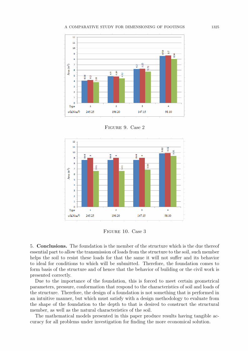
With regard to case 1 presented in Figure 8 shows that the largest difference is in the type1 of a 7.1%, this appears in the square footing and the smaller difference is shown of 1.8%in the type 3 for the rectangular footing. According to case 2 shown in Figure 9 presentsthat the largest difference is in the type 1 of a 10.5%, this is observed in the square footingand the smaller difference is of 6.7% in the type 4 for the rectangular footing. In termsof the case 3 presenting Figure 10 shows that the largest difference is in the type 1 and 2of a 36.2%, this is presented in the square footing and the smaller difference is of 5.0% inthe type 4 for the rectangular footing.
A COMPARATIVE STUDY FOR DIMENSIONING OF FOOTINGS 1325
Figure 9. Case 2
Figure 10. Case 3
5. Conclusions. The foundation is the member of the structure which is the due thereofessential part to allow the transmission of loads from the structure to the soil, such memberhelps the soil to resist these loads for that the same it will not suffer and its behaviorto ideal for conditions to which will be submitted. Therefore, the foundation comes toform basis of the structure and of hence that the behavior of building or the civil work ispresented correctly.
Due to the importance of the foundation, this is forced to meet certain geometricalparameters, pressure, conformation that respond to the characteristics of soil and loads ofthe structure. Therefore, the design of a foundation is not something that is performed inan intuitive manner, but which must satisfy with a design methodology to evaluate fromthe shape of the foundation to the depth to that is desired to construct the structuralmember, as well as the natural characteristics of the soil.
The mathematical models presented in this paper produce results having tangible ac-curacy for all problems under investigation for finding the more economical solution.

1326 A. LUEVANOS ROJAS
The models presented in this paper may be used in terms of the application of theloads. 1) Footings subject to concentric axial load. 2) Footings subject to axial load andmoment in one direction (unidirectional bending). 3) Footings subject to axial load andmoment in two directions (bidirectional bending).Then we recommend the model of circular footing for the structural design of isolated
footings subjected to axial load and bidirectional bending, because this is more econom-ical. Furthermore, this more adheres to the real conditions of the soil pressures that areapplied to the foundation.The mathematical models presented in this paper are applied only to rigid soils that
meet expression of the bidirectional bending, i.e., the variation of pressures is linear.The suggestions for future research may be, when is presented another type of soil, byexample in cohesive soils and granular soils the pressures diagram is not linear and shouldbe treated differently. Also another type of research that could be presented is the designof circular footings according to the rules of construction of the ACI (American ConcreteInstitute) for being the one that produced the most economical dimension.
Acknowledgment. This work is totally supported by the Facultad de Ingenieria, Cien-cias y Arquitectura de la Universidad Juarez del Estado de Durango, Gomez Palacio,Durango and Mexico. The author also gratefully acknowledges the helpful comments andsuggestions of the reviewers, which have improved the presentation.
REFERENCES
[1] J. E. Bowles, Foundation Analysis and Design, McGraw-Hill, 1996.[2] C. Villalaz, Mecanica de Suelos y Cimentaciones, Limusa, 2009.[3] B. M. Das, E. Sordo Zabay and R. Arrioja Juarez, Principios de Ingenieria de Cimentaciones,
Cengage Learning Latin America, 2006.[4] J. Calabera Ruiz, Calculo de Estructuras de Cimentacion, Intemac Ediciones, 2000.[5] M. J. Tomlinson, Cimentaciones, Diseno y Construccion, Trillas, 2008.[6] A. Luevanos Rojas, A mathematical model for pressures of ground acting on footings rectangular,
ICIC Express Letters, Part B: Applications, vol.4, no.1, pp.19-24, 2013.[7] A. Luevanos Rojas, J. G. Faudoa Herrera, R. A. Andrade Vallejo and M. A. Cano Alvarez, Design
of isolated footings of rectangular form using a new model, International Journal of InnovativeComputing, Information and Control, vol.9, no.10, pp.4001-4022, 2013.
[8] A. Luevanos Rojas, A mathematical model for dimensioning of footings rectangular, ICIC ExpressLetters, Part B: Applications, vol.4, no.2, pp.269-274, 2013.
[9] A. Luevanos Rojas, A mathematical model for dimensioning of footings square, International ReviewCivil Engineering, vol.3, no.4, pp.346-350, 2012.
[10] A. Luevanos Rojas, A mathematical model for the dimensioning of circular footings, Far East Journalof Mathematical Sciences, vol.71, no.2, pp.357-367, 2012.
[11] O. M. Gonzalez Cuevas and F. Robles Fernandez Villegas, Aspectos Fundamentales del ConcretoReforzado, Limusa, 2005.
[12] A. Parker, Diseno Simplificado de Concreto Reforzado, Limusa, 1996.[13] J. C. McCormac, Design of Reinforced Concrete, John Wiley & Sons, Inc., 2008.[14] M. L. Gambhir, Fundamentals of Reinforced Concrete Design, Prentice-Hall, 2008.[15] W. H. Mosley, J. H. Bungey and R. Hulse, Reinforced Concrete Design, Palgrave, 1999.[16] B. C. Punmia, A. Kumar Jain and A. Kumar Jain, Limit State Design of Reinforced Concrete, Laxmi
Publications (P) LTD., 2007.[17] W. A. Granville, Calculo Diferencial e Integral, Limusa, 2009.[18] N. Piskunov, Calculo Diferencial e Integral – Tomos 1 y 2, Limusa, 2004.