a) - bachelor of engineering (hons) civil | · web viewfigure 6: slip formworks with tower...
TRANSCRIPT

KUALA LUMPUR (K.L.) TOWER: THE SLIPFORMING WORKS OF THE SHAFT (By B.O.T. CONTRACTORS
WAYSS & FREITAG)
Authors: Dr. Yasmin Ashaari1 , Ir. Achmad Moerdijat2 , Ir. Dr. Aminuddin Baki1
1 Faculty of Civil Engineering, Universiti Teknologi MARA, Shah Alam Selangor2 Architect, Kumpulan Senireka Sdn Bhd, Kuala Lumpur
ABSTRACT
The technique of ‘slip’ formworks was utilised for the construction of the KL Tower. Once the construction of the foundation reached the ground, the preparation for slip formworks should start, where its basic methodology shall be developed quickly to meet the new challenging criteria because, there are 2 shafts. The internal lift core was relatively easier to built (straight vertical and thin) but the outer structural shaft was more complicated: First, it generally embodies a cone geometry which means the formworks need to be adjusted continuously (getting smaller and smaller in plan) as they are slipping upwards. Secondly, the structural design calculation demands that its bottom parts are much thicker than its top. Thirdly, through European perception, Wayss & Freitag imposed an “optical corrections” on to the surface of this gigantic column. Seen from the elevation, the cone lines are not just straight but instead, concave! Fourthly, in the case of KL Tower, the shaft must have ribs or flutes (no less than 16 numbers altogether) as part of the “Muqarnas” concept. All those problems on the structural shaft have been resolved by the Austrian specialist with surprisingly very simple technique: they choose a thin but rigid and strong materials i.e. merely 2mm thick steel plate segments as formworks. After traveling 266 metres away from the ground, both sets of formworks (internal and external shafts) will merge to become only one set, until reaching the level of Tower Head’s Roof (313m), where the job of slip formworks terminate and to be continued further by “jumping” formworks.
KEYWORDS: K.L. Tower, shafts, Slip formwork
1.0 INTRODUCTION TO K.L. TOWER PROJECT
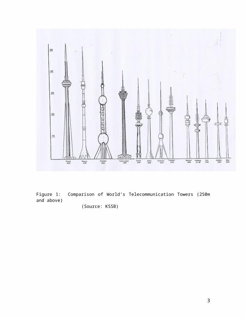
The Kuala Lumpur (K.L.) Tower at 420m can now be the nation’s pride as the fourth tallest telecommunication tower in the world (Figure 1). It all started with an idea by the then Minister of Information to commemorate the success of ‘Semangat Bersama Rakyat” (Semarak) campaign in the form of a monument, back in 1980’s era.
The monument turned out to be a very tall obelisk, no longer suitable for the Ministry’s compound. A German-Australian Marketing Consultant then suggested and convinced the decision maker that it is feasible to build the monument as real, functional Telecommunication Tower on top of Bukit Nanas. With the consent from the Ministry, the marketing consultant brought in Wayss & Freitag Germany for direct negotiation with
1

the Government’s officials. An organization was then formed to realized this dream (Figure 2) . The same team of consultants who have participated earlier during the conceptual stage was novated to the Main Contractors, Wayss &Freitag Malaysia Sdn. Bhd. who was contracted under the Build, Operate and Transfer agreement. All parties satisfied, the ground breaking ceremony was done in 1991 and on 1st October 1996, the Kuala Lumpur Tower was inaugurated.
Figure 1: Comparison of World’s Telecommunication Towers (250m and above) (Source: KSSB)
2
2.0 INTRODUCTION TO SLIP FORMWORKS
Generally, for straight vertical concrete structures, such like lift cores, contractors use special set of formworks where, immediately after the concrete hardened; inside it, the formworks then be jacked slightly upwards to form a new gap, to be filled up again with fresh concrete. As this sequence repeated after time, the tall structures can be completed with the same set of formworks. Hence the nickname of “slip” formworks.
How about the openings for doors and other horizontal ductings? On their exact location, the contractor will fix temporary “block outs” made from reusable materials with the exact size and thickness, so that those flanking special set of formworks can slip through but no concrete will seep in.
And how to construct the required interval floors within the shaft as required by ‘BOMBA’ the Fire Authority? So far, these are cast conventionally with the supporting struts underneath, well after the slip formworks passed by. Or, in the case of such a high
Minister of Information as Coordinator
Government of Malaysia
Syarikat Telekom Malaysia (STM)
Menara Kuala
Lumpur Sdn. Bhd.
(MKL)
BUILD, OPERATE (for 12 years)TRANSFER ORGANISATION
Wayss & Freitag
(Germany)
Wayss & Freitag Malaysia Sdn. Bhd. (WFM)
MAIN CONTRACTORS
CLIENT
Check Consultant: Ove Arup, London
KUALA LUMPUR TOWER PROJECT
Figure 2: Kuala Lumpur Tower Organisation Chart
CONSULTANTSArchitects: Kumpulan SenirekaC&S: Tahir WongM&E: JentrikQS: Baharuddin Ali & LowLandscape: Malik & Lip
3

volume below, the builder would place steel beams with edges nest nicely inside already cast wall niches, created by yet another block outs earlier. Figure 3 shows a section showing cantilevered steel beams at the Tower head installed using the same method.
Figure 3: Section of the Tower Head showing Steel Elements
(Source: KSSB)
4

3.0 UNIQUE SLIP FORMWORKS FOR K.L. TOWER
Once the construction of foundation reached the ground, the preparation for slip formworks should start, where its basic methodology shall be developed quickly to meet the new challenging criteria because, there are 2 shafts (Figure 4).
The internal lift core was relatively easier to built (straight vertical with thickness of 150mm) but the outer structural shaft was more complicated:
First, it generally embodies a cone geometry which means the formworks need to be adjusted continuously (getting smaller and smaller in plan) as they are slipping upwards. Secondly, the structural design calculation demands that its bottom parts are much thicker than its top: at ground level thickness is 1200mm reducing to 600mm at Level 266m. Thirdly, through European perception, Wayss & Freitag imposed an “optical corrections” on to the surface of this gigantic column. Seen from the elevation, the cone lines are not just straight but instead, concave! Fourthly, in the case of KL Tower, the shaft must have ribs or flutes (no less than 16 numbers altogether) as part of the “Muqarnas” concept.
All those problems on the structural shaft have been resolved by the Austrian specialist with surprisingly very simple technique: they choose a thin but rigid and strong materials i.e. merely 2mm thick steel plate segments as formworks.
By maintaining the position of the ribs fixed radially (with the compromised size of them now constant all the way) thus the only variables are the diameter of the shaft. So by ever reducing the inner and outer radii of it, the thin steel formworks are automatically moved and more overlapped each other and just sliding horizontally .
After travelling 266 metres away from the ground, both sets of formworks (internal and external shafts) will merge to become only one set, until reaching the level of Tower Head’s Roof at 313metres, where the job of slip formworks terminates and to be continued further by “jumping” formworks (Figure 5).
5

Figure 4: Section of K.L. Tower
(Source: KSSB)
6

Figure 5: Jumping Formworks
(Source: KSSB)
4.0 THE ANATOMY OF KL TOWER SLIP FORMWORKS
The complicated movements of those 2 sets of slip formworks (lift core and structural shaft) are controlled and coordinated by the Main Working Platform, fixed on top of them. Figure 6 shows the slip formworks with the Main Working Platform. It is well understood, that the size of this platform (which was the largest in the beginning and getting smaller as it moves up) is the size of inner core when both shafts merge eventually (Figure 7).
The design of Main Working Platform must address this stringent requirements. Further, there were still requirement for other working platforms that suspended from and moving in tandem with the Main one. The most important additional platform was located precisely inside the lift core and functions as logistic access for both materials and personnels.
This was also the landing platform for the easily extended Alimak or personnel hoist which was used as well for carrying up small size tools and materials. The wet concrete unadmirably, was carried using just big bucket from ground, pulled up by a low tech Winch, which was fixed onto this platform (Figure 8). The relatively long traveling time
7

was simply made up by adding calculated slow set admixtures. From here, the fresh concrete will be pumped up to Main Working Platform upstairs, continuously 24 hours a day.
On the other side, along the perimeter of the outer shaft, there were 3 levels of narrow (1 ½ m wide) but safe circular working platforms all suspended from Main Working Platform, where workers doing the finishes. On the top level, most of the touching up jobs be done (remember the 2mm thick kink left by overlapping and ever sliding steel plate formworks?)
While the middle platform is responsible for applying undercoat, the bottom level is for the final paint.
Coming back to the Main Working Platform, the utmost important mechanism centre there, is the Hydraulic System Station, where all jacks (about 16 sets) are manually and carefully synchronized. The Tower Crane, oddly enough was fixed slightly off, occupying one of the 4 Lift Shafts, thus leaving the centre to the Concrete Distributor that was being fed by the Concrete Pump below. In this way, the distributor can rotate 360° but minus whatever space occupied by the crane but the area behind it still can be reached easily by the Distributor’s “tentacles”.
Another essential device here (albeit smaller) is the Laser Plumber that also moved up together with the entire set of Slip Formworks. It controls not only the verticality of the shaft but as well to avoid any spiraling. When the formworks are getting nearer to the sky, the surface of the outer shaft was so huge that even the morning sun could generate enough heat to make this concrete structure leaning westwards. That is why the plumbing works were normally done around 3 a.m, daily.
8

Figure 6: Slip Formworks with Tower Crane attached to its Main Working Platform
(source: KSSB)
9

Figure 7a Sections of the Shaft (note: scaled drawings reduced to fit)
10

Figure 7b: Typical Details
(note: scaled drawing reduced to fit)
11

Figure 8: Cross Section of the Slip Formwork System
(note: scaled drawing reduced to fit)
12

5.0 CONCLUSIONS
1) Although BOT (Build Operate & Transfer) contract is supposed to transfer the technology and knowledge involved, but it must be admitted due to the fact that the speed of this slip formworks were so fast (6 M in a day and one night) and, the specialists apparently and understandably still have some trade secrets to protect, have made the transfer not fully achieved.
2) During the construction there were slight grumbling voices now and then by those very experienced contractors in relation to the “first in the world” slogan and difficult detailings insisted by the Architects backed up by the clients, to include the then Prime Minister.
But, having completed one of the Malaysian identity, the German Main Contractors now boasts KL Tower is their pride.
3) Finally, on the bright side of the ventures, one might conclude that this is an example where a strong architectural concept could give birth to a new invention in construction industry.
REFERENCES
KSSB (Kumpulan Senireka Sdn Bhd), unpublished drawings and photos.
13