a 5,730-hr cyclic endurance test of the...
TRANSCRIPT

23 - IEPC-95-179
U A 5,730-Hr Cyclic Endurance Test Of The SPT-100
Charles E. Gamer, John R. Brophy,* James E. Polk*, and Lewis C. Pless+
Jet Propulsion LaboratoryCalifornia Institute of Technology
Pasadena, CA 91109
Dan A. StarlingNaval Postgraduate School
Monterey, CA
ABSTRACT space, starting with the Meteor I in 1969-1970.7.8 Morerecently, eight SPT-100 thrusters were flown on the Russian
A cyclic endurance test of the Russian 1.35 kW Stationary GALS television satellite to perform both north-south andPlasma Thruster SPT-100 is described. The endurance test east-west station-keeping functions.9was performed for 6,925 on/off cycles and 5,730.3 hours ofoperation at an input power to the thruster of 1.35 kW. In 1991 a team of electric propulsion specialistsEach cycle was approximately 50 minutes of thruster on- visited the former U.S.S.R. to experimentally evaluate thetime and 23 minutes of thruster off-time. Thruster efficiency performance of a 1.35-kW SPT at the Scientific Research
1,000 hours. The efficiency increased slowly over the next Bureau "Fakel" in Kaliningrad, Russia. 10 -1 1 The1,000 hours and then slowly decreased to 45% by the end of evaluation verified that the actual performance of the thrusterthe wear test. The unused cathode ignitor and radiation was close to the claimed performance of 50% efficiency at ashieldswerefoundto erode anunexpectedy highrate. A specific impulse of 1600 s.10 Studies indicate that forshields were found to erode at an unexpectedly high north/south station keeping and Earth orbit raisingshort between the cathode emitter and cathode ignitor applications of electric propulsion, the optimum specificoccurred at cycle 5,316; the short was cleared without impulse is in the range of 1.000-2.000 sec. 12 Theopening the vacuum tank but the short reoccurred at cycle combination of the flight heritage of the SPT-70 and the6,344. The vacuum chamber was opened after the thruster availability of thrusters and thruster data led to substantialhad accumulated 6,346 cycles and 5,250 hours of operating interest in these thrusters by Western spacecrafttime to clear this short and repair the thrust stand, which had manufacturers for primary and auxiliary propulsionfailed at cycle 5,818. The wear test was continued and applications.voluntarily terminated when 5,002.5 hours of operation wereaccumulated on cathode #1. Data from this wear test indicate Space Systems/Loral is presently flight-qualifyingthat the likely first failure mechanism for this thruster design SPT-100 thrusters for north/south station keeping and Earthis shorting between the ignitor and cathode emitter in the orbit raising applications and plans to provide these thrustersunused cathode. The endurance test was performed under a on their spacecraft. 13 At Design Bureau "Fakel", a steady-cooperative program between Space SystemsLoral, JL, and state life test was performedl 4 , and performance, plume andEIprogram between Space Syste Lal, JP, and E /RFI evaluations were conducted at NASA Lewisthe Ballistic Missile Defense Organization (BMDO). Research Centr.1 AS-18
INTRODUCTIONNTRO CTION A key aspect of the SPT-100 evaluation programStationary plasma thrusters (S ) are griless ion was characterization of the long term operating behavior of
thrusters that were originally developed in the US. in the the thruster. Typical mission applications of interest requiretht we originy d d e U .in te operating times of several thousand hours. Potential use ofearly 1960's. 1 3 Although efforts in the U. S. to develop the thruste for north-south station keeping of commercialhigh thrust efficiencies failed, efforts in the former U.S.S.R. communication satellites will also require the capability for
were quite successful. The SPT was successfully developed several thousand on/off cycles. To address these objectives aduring the 1960's and 1970's by Morozov 4 and others5 ,6 to cyclic endurance test was performed at JPL under aobtain a unique combination of specific impulse and cooperative program between Space Systems/Loral, JPLefficiency. More than 50 SPT-70 thrusters have flown in (under the JPL Affiliates program) and the BMDO. The
original goal for the test was to accumulate a total of 5,000SMember of the Technical Staff, Advanced Propulsion hours and 6,000 cycles on the thruster; the test was extended
Technology Group. to accumulate more than 5,000 hours of operating time on a+ Member of the Technical Staff, Electric Power Systems single cathode. Several papers describe the wear test resultsSection. through the first 5,000 cycles. 19 -2 1 *Tis paper describes the** Supervisor, Advanced Propulsion Technology Group. results of this cyclic endurance test for 6,925 cycles and
5,7303 hours of operation at 1350 watts.
I
- 1234 -
APPARATUS operating the SPT, the propellant system was checked fordew point, hydrocarbon contamination, and particulate
The Russian SPT-100 plasma thruster used in this contamination. The xenon supply pressure was indicated byendurance test is shown in Fig. 1. This thruster as tested a capacitance manometer that was calibrated to an accuracy ofcomes with two hollow cathodes and a xenon flow control ±0.25% at 249.94 kPa, the nominal working pressure for thesystem (XFC) enclosed in a box directly behind the SPT-100 SPT-100. This pressure was then dropped to the level(Fig. 2). The outer insulator which forms the outside required by the cathode and discharge chamber within thedischarge chamber wall is approximately 100.8 mm-dia. In xenon flow control system (XFC) that is an integral part ofthis endurance test the cathode at the top (cathode #1) was the SPT-100 and is located directly behind it in the vacuumused as the primary cathode. system. Therefore the pressure in the propellant tubing was
above atmospheric pressure up to the SPT XFC. TheThe SPT-100 thruster endurance test was performed purity of the xenon used by the SPT was tested directly from
in a 3.1-m dia. x 5.1-m stainless steel vacuum chamber the xenon bottle. Purity data indicate that the specificationsequipped with three each, 1.2-m diameter helium cryopumps. (99.999%) were exceeded.The minimum no-load tank pressure was observed to be 4.2x10⁻⁶ Pa (3.2 x 10⁻⁸ Torr). The rated pumping speed for the A thermal mass flow meter was used to measure thethree pumps combined is 81,000 liters/s on xenon, however total propellant flow rate. The flow meter was calibrated onthe measured pump speed on xenon is approximately 50,000 both nitrogen and xenon by the manufacturer using a primary/s. calibration standard, and at JPL using a bubble volumeter.
The nitrogen calibration performed at JPL agreed with theThe thruster was mounted near one end of the primary standard calibration to within 1% for all flow rates
vacuum tank, directly facing a cryopump which is positioned tested. The bubble volumeter data on xenon were curve fitat the other end of the vacuum tank. The discharge chamber and the curve fit was incorporated into the SPT data •surfaces of the SPT thruster consist of insulator materials, acquisition and control program.and it has been demonstrated that the performance of SPTthrusters can be significantly affected by the deposition of a A xenon recovery system was used to recover andconducting coating on the insulator.2 2 To protect the store xenon consumed by the SPT-100 and is described incryopump and minimize the amount of material sputtered Ref. 19. A probe rake, consisting of 25 Faraday probes of Iback to the thruster, the facility was lined with graphite, and diameter 2.3 cm, mounted on a semicircular arc 2.4 m ina graphite beam target was constructed. The beam target diameter was used to examine the thruster exhaust plume.consists of 6.4-mm thick graphite panels arranged in a The probe buttons were biased to -23 volts when used tochevron configuration and placed as shown in Ref. 19. measure ion current in the plume. The probe rake wasGraphite was selected as the target material because of its positioned such that the thruster is at the center of thelow sputter yield at the ion energies expected from the semicircular arc; the axes of the rake were aligned with the *SPT. 23 The chevron configuration results in large angles plane formed by the outer insulator of the SPT-100 such that(typically greater than 50 degrees) between the expected ion the rake can be pivoted around a line normal to the thrustertrajectories and the direction normal to the graphite surface, axis. This configuration enables complete hemisphericalwhich may both reduce the graphite sputter rate and reduce profiles of the exhaust plume to be made. When the probethe amount of sputtered material directed back towards the rake is not in use, a motor rotates the rake to a position ofthruster. A photograph of the SPT-100 mounted inside the approximately 90 degrees with respect to the thruster axis.vacuum chamber is shown in Fig. 2.
The SPT-100 was mounted to an inverted pendulumDue to the beam divergence characteristics of the style thrust stand of the type developed at NASA LeRC; 24
SPT-100, material can be sputtered from the vacuum tank in this design, thrust is indicated by a linear voltagesidewalls and deposited onto the thruster. Therefore the displacement transducer (LVDT). The thrust stand iscylindrical side walls of the vacuum chamber were also lined surrounded by a water-cooled housing to minimizewith graphite panels. Glass slides were placed 21 cm to temperature effects on the measured thrust; the housing caneither side of the SPT thruster such that material back be seen just below the SPT-100 in Fig. 2. The thrust standsputtered to the SPT could be quantified and characterized, inclination was adjusted continuously by computer to
improve the accuracy of the thrust measurement overTank pressure was measured using two ion gauges. extended test times. Thrust stand calibrations were performed
One gauge tube was mounted directly to the outer wall of in-situ throughout the life test using a set of weights.vacuum tank; the other tube was mounted inside the vacuum Normally 15 or more data sets were performed in order totank, approximately 0.51 m above and 0.58 m behind the obtain a large enough sampling for statistical analyses.SPT-100. This tube was calibrated on xenon and nitrogen Statistical analyses of the calibration data was also used tousing a spinning rotor gauge that is traceable to NIST. determine the best thrust stand inclination setting. •
Repeatability of the calibrations were normally 1.0% or IThe propellant system for supplying xenon to the better.
SPT-100 thruster is described in Ref. 19. The system wasconstructed from 0.64-cm-dia stainless-steel tubing that wasscrubbed with acetone and alcohol before assembly. Prior to
I
I - 1235 -
The thruster was operated with a bread board power The computer issued the PCU start and stopconditioning unit (PCU) developed by Space Systems/Loral. commands. If certain engine or facility parameters exceededThe SPT-100 discharge current and magnetic field current specifications, the computer sent the PCU stop command towere adjusted by supplying the appropriate voltage input the PCU, opened a relay between the PCU and its powersignal to the PCU. The PCU output voltage was fixed at source, and activated a telephone dialing machine (autodialer).approximately 300 V. Propellant flow rate was controlled The computer sent a change-of-state signal every 15 secondsby the SPT-100 flow control unit which is pan of the to an electronic timer (heartbeat box); in the event of athruster, the mass flow rate was determined by the discharge computer failure, the timer activated a series of relays to tumcurrent setting. The PCU was turned on and off by off PCU power, xenon flow, and activates the autodialer.supplying the appropriate digital signal to the PCU. Oncethe engine parameters were adjusted and the PCU was turned PCU telemetry for various SPT-100 currents wereon, the SPT-100 thruster was started and operated calibrated to values obtained from calibrated current shunts.automatically by the bread board PCU. The PCU/thruster The discharge current calibration was determined using asequencing is described in Table. I for one complete cycle, voltmeter which averages the direct-current value of the
discharge current shunt voltage drop over a period of fourseconds. Oscillations in the discharge current were obtained
Table I. PCU/Thruster Sequencing For One Complete Cycle with an inductive probe placed on the discharge currentcable close to the vacuum tank feed through. The dischargevoltage ripple was measured at the vacuum tank feed through
Tune Action as well, using a combination inductive/Hall effect probe.sec Cabling length between the feed through and SPT is
approximately 6 m. After cycle 663 of the cyclic life testthe RMS value of the discharge current was measured using a
0 PCU start command received from true RMS voltmeter.computer
The thruster was photographed (from an off-axis10 Cathode heater, capillary current, view) periodically through a window in the vacuum system
magnetic field current on to document the condition of the thruster. Insulatorthicknesses were determined from photographs by measuring
170 Cathode ignitor voltage applied; cathode the ratio of insulator width to the outer diameter of the outerheater off. insulator or inner diameter of the inner insulator. An off-axis
view of the SPT-100 is shown in Fig. 3. The SPT-100 can171 SPT achieves 1.5 A discharge; run time be seen operating in the endurance test facility in Fig. 4.
clock started, begin on-phasePROCEDURE
180 SPT achieves 4.5 A dischargeThe SPT-100 was purged with xenon when the
3180 SPT turned off by stop command issued mechanical pumps were used to pump the vacuum tank fromby computer, begin off-phase atmosphere to 50 mTorr. The SPT-100 was operated only if
the vacuum tank pressure indicated by the calibrated ion4380 PCU start command received from gauge reads below 2.7 x 10- 5 Pa (2 x 10⁻⁷ Torr). During a
computer for next cycle facility shutdown (cryopumps off) the SPT-100 was purgedwith xenon.
A cycle is defined as any time the thruster achievesSteady-state thruster operation, start-up and a discharge current of >1.5 A. The first 26 cycles of the life
shutdown sequencing were controlled by a PC based data test were used to test the data acquisition and controlacquisition (DAC) system. This system also monitored the program, the facility, and the probe rake; in these cycles thevacuum facility enabling unattended operation. A total of 56 thruster was operated for varying time periods, from less thanchannels that include thrust, xenon mass flow rate anode one minute to over 60 minutes, and at varying discharge
voltage and current, floating voltage, magnet current, cathode c nts.heater current, thermothrottle current, SPT inlet xenon The computer performed the task of starting andpressure, tank pressure and various other facility components stopping the thruster, taking data, and monitoring thewere monitored and recorded as a function of time. The data facility. Oscilloscope traces of oscillations in the dischargewere averaged in real time and the averaged values were current and AC ripple in the discharge voltage were obtaineddisplayed on a monitor screen. The data were recorded on the approximately every 10 cycles. Approximately every 200computer hard disc drive every 30-60 seconds. hours the life test was interrupted for a short period of time
to photograph the thruster, measure flow meter zero drift, andto re-calibrate the thrust stand (T/S). Approximately every200 hours a probe scan was obtained using the probe rake.
U
- 1236 - I
RESULTS AND DISCUSSION Hardware failures consisted primarily of xenonregulator pressure failures or cryopump cooling waterfailures. Computer/DAC failures consisted of printer
DESCRIPTION OF WEAR TEST CYCLES failures, software crashes and loose cabling. Operator-induced shutdowns consisted of various actions resulting in a
Thruster operating hours vs. cycle number is plotted computer-commanded shutdown.in Fig. 6. Starting with cycle 27 the SPT-100 was cycledfor 50 minutes on and 20 minutes off, with 3 minutes forcathode pre-heating. The SPT-100 completed 6,925 starts and WEAR TEST SIGNIFICANT EVENTS5,730.3 hours of operation; of these, 103 cycles totaling32.73 hours were not operated for the standard 50 minutes A glow in the non-operating cathode was observedbecause of testing requirements, computer/facility failures, beginning in cycle 1. This SPT-100 thruster utilizes aoperator error, or to computer-commanded shutdowns. There propellant system with no absolute flow shut-off to thewere no shutdowns required due to abnormal SPT operation. unused cathode.2 Newer designs include positive flow shut-In all cycles the SPT always performed to its nominal off to the unused cathode. The glow in the unused cathode isoperating condition of 1.35 kW. Non-standard cycles are visible in a photograph (Fig. 5) of the SPT-100 incategorized in Table II. operation. The brightness of the glow appeared to decrease
with time.
Table II. Test/shutdown descriptions Unexpectedly high ignitor wear rates in the unusedcathode (cathode #2) were observed soon after the start of thewear test On cycles 5,316 and 6,344 the cathode ignitor
Shutdown Description Number of Shutdowns shorted to the cathode emitter. Two other failed thruster start Iattempts at cycles 561 and 6,879 were attributed to other,
Thruster/DAC testing 33 non-thruster causes that can be summarized as follows: nostart signal sent by computer, start signal not received by
PCU/PCU input power 22 PPU, or PPU ignitor start circuit failure.supply failures
Between cycles 1,545-1,744 a thrust standCryopump failures 20 calibration weight was inadvertently left deployed on the
thrust stand, therefore no thrust measurements for theseComputer/DAC errors 16 cycles are available. Ten minutes after the completion ofor hardware failures cycle 2675 an earthquake shook the thrust stand hard enough
to cause the middle 3-gram mass in the thrust standOperator-induced shutdowns 8 calibration system to slip down to the end 3-gram mass.
Therefore only two masses, 3 grams and 9 grams, could beCycle stopped manually, 2 used for thrust stand calibrations until after cycle 6,346,thruster emitting sparks when the vacuum tank was opened and the thrust stand was
repaired. After cycle 5,817 a software error in the DACPower grid transients 2 program caused the thrust stand tilt motor to jam at it's
extreme position, therefore between cycles 5818-6346 noTOTAL 103 thrust measurements were possible. The tilt control
assembly was repaired simultaneously with the calibrationweights. 3
After cycle 5,661 one of the cryopumps failedA total of 33 cycles were operated at various time completely. The wear test was continued with only two
intervals to test the thruster or DAC system. Twenty-two cryopumps operating until the pump was repaired after cycleshutdowns were commanded by the computer due to PPU 6,176. Therefore, the tank pressure between cycles 5,661-module failures or PPU input power supply failures; the 6,176 was 2.5x10⁻³ Pa (1.9 x 10⁻⁵ Torr), compared to thedischarge voltage decreased up to 6 volts when a PPU usual 1.9 x 10⁻³ Pa (1.45 x 10⁻⁵ Torr). It was not necessarymodule failed. Twenty shutdowns were due to cryopump to open the vacuum tank to repair the cryopump. After thefailures. The shutdowns were commanded by computer when pump was repaired the tank pressure returned to the normal Ia cryopump failed and vacuum tank pressure exceeded 0.013 load pressure of 1.9 x 10⁻³ Pa.Pa (10 4 Torr), or when a cryopump temperature sensorfailed. Tank pressure did not exceed 0.04 Pa during thesefailures. Xenon flow through the SPT was maintained whena cryopump was turned off.
Ii
- 1237 --
STEST DATA FOR CYCLES 26-6925 Mass Flow Rate and Discharge Current
Engine parameters such as efficiency, discharge Mass flow rate and discharge current are plotted as acurrent and voltage, thrust and specific impulse for cycles 26- function of thruster cycles in Fig. 8. For a fixed mass flow6,925 are shown in Figs. 7-10. Thruster data were analyzed rate of approximately 5.5 mg/s the discharge currentto determine cycle-to-cycle changes in thruster operating decreased approximately 0.4% over 6,925 cycles. Thecharacteristics. Thrust was determined by subtracting the thermal mass flow meter calibration drifted approximatelyLVDT voltage four minutes after the SPT was turned off 1% between run hour 0-1,740; in the data presented in Fig.from the LVDT voltage obtained from averaging LVDT 8. the mass flow indicated by the flow meter was adjustedvoltage over the last ten minutes of the cycle, and with the assumption that the drift rate was uniform betweenmultiplying by the appropriate thrust stand calibration factor, run hour 0-1,740.Efficiency and specific impulse were calculated using thevalues for thrust, mass flow rate, and engine power Thrust Efficiency and Snecific Impulse(including magnet power), averaged over the last 10 minutesof the cycle. Thrust and efficiency are plotted as a function of
thruster cycles in Fig. 9, and thrust and specific impulse areSLarger variations in thruster parameters such as plotted in Fig. 10. The data indicate that the thrust decreasedfloating voltage and thrust occurred in the first 900 hours of until app. cycle 1,000, whereupon the thrust began tothruster operation than in the rest of the test. In most cases increase until approximately cycle 3,000. Between cyclesthe variations were intentionally induced by applying 3,000-6,925 the thrust decreased approximately 1.5-2 mN.supplementary current to the magnet coils to investigate At the end of the wear test the thrust was app. 81-82 mN,thruster performance and oscillations in the discharge current compared to 85 mN at the beginning of the test. The shapeand voltage, of the thrust vs. cycles curve is surprising and counter to
expectations; it is not understood how or why the thrustincrease occurred after cycle 1,000. However, the thrust data
Discharge Volge are qualitatively similar to data obtained from a steady-stateendurance test performed by Fakel Enterprises. 1 4
Discharge voltage is plotted as a function of thruster Theoretical analyses of the thrust increase with time wascycles in Fig. 7. Discharge voltage was measured between presented in Ref. 14. Efficiency and specific impulse, ofthe anode and cathode emitter. Between cycles 1-810 the course, tracked the shape of the thrust curve; by the end ofdischarge voltage was monitored via PPU telemetry; after the wear test thruster efficiency had decreased to 0.45-0.46.cycle 810 the discharge voltage was measured using a voltageattenuator. Variations in discharge voltage observed through Discharge Current Oscillations and Voltage Riople
failures or PCU discharge supply module failures; without Oscillations in discharge current and voltage areall modules functioning the engine discharge loaded down the shown in Figs. ll(a)-ll(c). The probes used to measurePCU and the output voltage dropped approximately 6 V. discharge current and voltage oscillations were positionedVariations in discharge voltage observed through cycles close to the vacuum tank feed through and downstream of the5,300-5,600 were due to placement of ammeters in series PPU output filter. There was approximately 6 m of cablewith the discharge; since the PCU output voltage was fixed, length between the tank feed through and the thruster. Thethe impedance of the ammeters resulted in a small decrease in data were taken approximately every ten cycles.the discharge voltage.
hoa eVolCopies of oscillographs taken from cycle 27 andEiating Ygltage cycle 6,925 are shown in Figs. 11(a)-ll(b). Theoscilloscope was triggered using the current probe such thatFloating voltage is plotted as a function of thruster the oscilloscope would trigger every 15 seconds. Peakcycles in Fig. 7. Variations in floating voltage through values for oscillations in discharge current and voltage for
approximately cycle 1,000 were due to intentional changes in cycles 1-6.925 are shown in Fig. 11(c). In Ref. 19 reducedthe auxiliary magnet current.19 Following that the floating current and voltage oscillation amplitudes were associatedvoltage increased to a maximum at cycle 1,300, then with improved thruster performance. Initially, dischargedecreased until approximately cycle 2,100. The SPT-100 current oscillation amplitudes were generally less than 2 A p-was operated on cathode #2 (the redundant cathode) at cycle p. and voltage ripple less than 2.5 V p-p. By cycle 1,1005,321, then again between cycles 5352-6,196. The floating (run time 890 hrs) current oscillation amplitudes were 10 ASvoltage was generally higher by 2.5-3 volts when the p-p, and up to 15 V p-p ripple in the discharge voltage.thruster was operated on cathode #2. The floating voltage Oscillation amplitudes began to decrease at approximatelyalso increased slightly when the thruster was operated with cycle 2,500 (2,043 hrs run time). By cycle 6,925 currentonly two of the cryopumps functioning (cycles 5,661- oscillation amplitudes were only 5 A p-p maximum and 106.176), which resulted in a 32% increase in tank pressure, volts p-p maximum for the discharge voltage; these valuesAs can be seen, there is little difference in the floating are similar to those obtained at the start of the wear test.voltage between the start and end of the wear test The data from Fig. 1 (c) can be fitted to a Gaussian function;
both curves peak near cycle 1,675.
I

- 1238 -
Changes in cathode #2 can be seen in thePlume Characterization photographs in Figs. 20-25. By cycle 358 (run time = 281.5
hrs) there were indications that cathode #2 was being eroded.The current density measured by the center probe of In Fig. 20 the erosion appears as a light crescent at the top
the probe rake for two different cycles, cycle 759 and cycle of the ignitor. There is also a discoloration near the ignitor6,925, are compared in Fig. 12. There appears to be little orifice. The crescent-shaped area increased in size (Figs. 21-change in the shape of the exhaust plume over 6,200 cycles 22 ) and there are indications of erosion in the ignitors ofand 5,200 hours, except that the peak current density both cathodes in a direction radially towards the dischargedecreased approximately 8% relative to the current density chamber. In Fig. 23 the front face of the ignitor has beennear the start of the wear test roughened and it appears that the whole face is being eroded.
By cycle 2,676 (run time = 2191.34 hrs) the ignitor cover onInsulator Erosion cathode #2 wore through completely at approximately the
12:00 o'clock position (Fig. 24). By cycle 4,703 (run timeErosion of the discharge chamber insulator surfaces = 3,882 hrs) the ignitor face on cathode #2 had disappeared.
was documented photographically and is plotted in Fig. 13 as In Fig. 25 the tip heater of cathode #2 is on.a function of run time. Results indicate an erosion rate thatis approximately the same as reported in Ref. 26. The data The data indicate that ions coming from the regionin Fig. 26 were obtained from steady-state wear tests between the two cathodes eroded the front face of the ignitorperformed in the former Soviet Union. The data imply that of the unused cathode, with the heaviest erosion occurringthere is no significant change in the wear characteristics of near the top of the ignitor. There was a plasma glow insidethe SPT-100 when it is operated in cyclic testing, the unused cathode from the start of the test (Fig. 5) but it is
unknown what the impact of the plasma inside the unusedWear characteristics of the SPT-100 are shown in cathode was on ignitor/cathode erosion. Since the ignitors
Figs. 14-19. In Fig. 18 the tip heater for cathode #2 is on. and emitters of both cathodes were connected together, it isThe dark material on certain locations of the SPT-100 may difficult to understand the wear characteristics of the SPT-100be uneroded deposits of graphite sputtered from the graphite cathodes. Understanding of the wear mechanisms isbeam target or boron eroded from the insulators and complicated by the propellant leak in the non-functioningredeposited onto various locations on the thruster. The cathode.arrival rate of back-sputtered graphite onto glass slideslocated near the thruster was measured using a profilometer On cycle 5,316 (run time = 4392.7 hrs) a shortthe data indicate that the back-sputter rate varied between 6.6- developed between the emitter and ignitor of cathode #2 and7.6 x 10-4 urn/hour. the thruster did not start. The short appeared to be due to
accumulation of sputtered material that bridged the ignitor toThe photographic records of this wear test indicate the cathode emitter radiation shields at the 7:00-10:00 o'clock
that by approximately run hour 75 grooves had formed in the position (Fig. 25). In the thruster configuration used for theouter insulator, by run hour 2,189 the downstream metallic wear test the ignitors and emitters of both cathodes areface of the SPT-100 was just beginning to be eroded by ion connected together, resulting in cathode #1 being shorted asbombardment because the outer insulator was worn flush well, and the thruster could not be started because of powerwith the thruster surface. Inner insulator erosion was drain to the ignitor high voltage start supply. The thrustersomewhat asymmetric; at the end of the wear test the inner was allowed to cool to room temperature, and the followinginsulator was reduced in thickness to approximately 1 mm at 5 thruster starts were successful. However, the short againthe 12:00 o'clock position (the cathodes are at 8:00 o'clock developed on cycle 5,321 and the thruster could not beand 10:00 o'clock), 0.5 mm across from the cathodes and at started. With a thruster temperature of approximately 206:00, and adjacent to the cathodes the thickness was degrees C, the isolation between the ignitor and cathodeessentially zero millimeters. emitter was 0.8 ohms.
Cathode Erosion To clear the short the tip heater of cathode #2 washeated to 11.5 A and the thrust stand was wiggled with the
Cathode #2 eroded considerably even though it was tip heater cycled on/off; this was the first time the tip heateroperated for only 890 cycles and 727.8 hours in this wear on cathode #2 had been turned on. It was not necessary totest, and was not operated at all until cycle 5321. This was open the vacuum chamber to perform the above procedures.the most surprising and unexpected result of the wear test; After several iterations of the above described procedure thedata from previous tests conducted in the former Soviet ignitor/emitter isolation had increased to several hundredUnion were obtained with both cathodes being operated for ohms with the redundant cathode's ip heater hotan equal amount of time, and cathode erosion was assumed to ,occur in the used, not unused, cathode. However, n c yc le t532 the thruster w a s started on cathodephotographic evidence obtained in this wear test are 2 for the first time. The thrster started without difficulty,conclusive that in this thruster configuration it is the unused despite the fact that the cathode ignitor was heavily erodedcathode that erodes at the highest rate. and the cathode emitter possibly contaminated with metal
deposits from the nearby sputtering of the ignitor andpossibly the radiation shields. The thruster was operated forone cycle; these actions increased the isolation between the
I

- 12359 -
ignitor and the emitter to 1.24 kohms (thruster cold). The was eroded completely through; at these locations thethruster was operated for a total of 727.8 hours and 890 thruster body was eroded by discharge chamber ions. Deepcycles on cathode #2. lines and trenches characteristic of SPT insulator erosion
marked the leading edges of the insulator (Fig. 31). TheA major technical goal of the wear test was to inner insulator thickness at the downstream end varied with
demonstrate 5,000 hours on a single cathode, hence thruster position, as described previously.operation was switched back to the primary cathode (cathode#1) after 6,196 cycles and 5125.5 hours of operating time. A black deposit upstream of the erosion zoneThe thruster started without difficulty and was operated on covered the interior walls of both the inner and outercathode #1 until cycle 6344 (run time = 5,248.4 hrs), when insulators (see Fig. 20); the deposit was primarily boron,a short again developed between the ignitor and cathode with some silicon, oxygen and a trace amount of xenon.emitter. The thruster was operated for two more cycles, then The anode was covered by a very light film deposit (not yetthe vacuum chamber was opened to inspect the thruster and analyzed); the electrical resistance across this film wasrepair the thrust stand. This was the only time in the wear measured using a flat electrode with a diameter of 2.5 mmtest that the vacuum chamber was opened to atmosphere. that was pressed flat onto the anode. The resistance acrossVenting of the vacuum chamber was performed using dry the film varied between 0.8-1.2 ohms and was a minimumnitrogen, diagonally across the cathodes and a maximum near the
cathodes.A physical inspection of the thruster indicated that
the short developed in the redundant cathode between the The downstream face of the thruster body was erodedignitor and the cathode radiation shields via deposits at the as a ring approximately 2 mm deep. Pits were eroded in the8:00 o'clock position. The short was cleared by scraping the thruster body at locations underlying those areas of the outerdeposits away with tweezers; in addition, the redundant insulaor that had eroded completely away where the outercathode was separated electrically from the primary cathode insulator eroded comrpletely away. Through-holes wereby cutting the wire cable to the redundant cathode, eroded completely into the thruster body at the four locations
adjacent to the electromagnets, with the largest hole 1 mm xThrust stand repairs were also performed: the tilt 7 mm long and located at the 1:30 o'clock position. At the
motor assembly was unjammed, the second weight was 11:30 o'clock position there is a crescent-shaped hole in themoved to it's proper location, and the tank was pumped thruster body that is 05 mm x 13 mm. The holes at thedown. Total time of thruster exposure to atmosphere was 4:30 o'clock and 7:30 o'clock positions barely go throughapproximately 25 hours. The thruster was restarted on the thruster body. Screw heads or screw ends at variouscathode #1 100 hours after exposure to atmosphere; the wear locations on the face of the thruster body show signs oftest was completed using cathode #1. erosion (Fig. 31). The thruster face was covered with a
metallic deposit that was heaviest between the 8:00-11:00So'clock positions (cathode #1 is located at 9:30 o'clock and
Thruster Characteristics For Cycle 6.925 cathode #2 at 8:30 o'clock). The deposit consisted primarilyof molybdenum, the same material used for the ignitor.
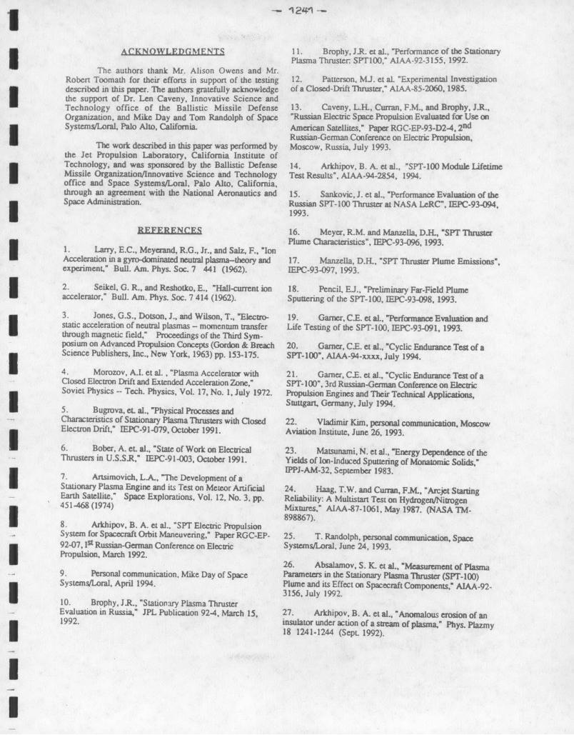
Thruster operating characteristics for cycle 6,925 areshown in Figs. 26-28. Variations in thruster discharge A metallic layer was observed spalling off of thevoltage and current are due partly to noise in the data electromagnets that are located next to the cathodes.acquisition system; no variations in discharge current and Analysis indicates that the metal film is primarily iron andvoltage were observed in the panel meters, and the voltage nickel. No films were observed on the other twoinput (for discharge current and voltage) to the DAC system electromagnets located across from the cathodes at 1:30was essentially a constant. The changes in thrust in the o'clock and 4:30 o'clock positions.first 500 seconds indicated in Fig. 28 are due to changes inthe thrust stand tilt and not to changes in thrust The data in The ignitor of cathode #1 showed evidence of directthese figures indicate that in the last cycle of the wear test impingement by ions coming from the discharge chamber.the thruster operated and performed very well. In Fig. 32 the wear pattern on this ignitor begins at 12:00
o'clock and ends at 6:00 o'clock. The front face of theignitor has shallow grooves. Analysis of metal deposits on
Post-Test Inspection the outside surface of this ignitor indicates that the materialis primarily molybdenum and iron. The ignitor orifice of
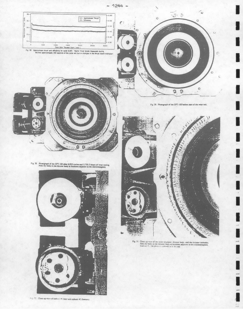
Photographs of the SPT-100 thruster new and after cathode #1 increased in diameter, from a circle of6.925 cycls and 5,730.3 hrs are shown in Figs. 29-32. The approximately 6.3 mm dia to an ellipse of dimensions 9 xmost striking features concerning erosion in this thruster are: 10 mm; the side of the ignitor orifice facing away from thecomplete erosion of the downstream end of the outer SPT-100 eroded the most.insulator, erosion of the downstream face of the thrusterbody, and erosion of the ignitor in cathode #2. Inside the ignitor of cathode #1 a small metallic
deposit formed at the 9:00 o'clock position (Fig. 32). ThePost-test inspection of the thruster revealed that the cathode orifice diameter increased, from 1.2 mm at the start
outer insulator was eroded completely away at the of the test to a chamfered surface of diameter 1.6 mm at thedownstream face. At various locations the outer insulator end of the test. A crystalline deposit was formed near the
I

- 1240 -
downstream end of the cathode orifice. The small sliver of CONCLUSIONS •material located inside the cathode spalled from anundetermined location after the thruster was removed from An endurance test of an SPT-100 was performed forthe vacuum chamber and transported by vehicle to another 6,925 on/off cycles and 5,730.3 hours of operation at anlocation to be photographed. input power of 135 kW. The endurance test was initiated
July 1, 1993 and ended on November 21, 1994. TheThe downstream face of the ignitor for cathode #2 nominal cycle duration was 50 minutes on and 23 minutes
was completely destroyed; metallic deposits were observed on off, including nearly three minutes of cathode preheat time.the ignitor at 6:00 o'clock-9:00 o'clock. The multi-layer The SPT-100 was powered by the Loral breadboard PPU.cathode radiation shields also eroded at a high rate; in Fig. 32 The original test objectives, to demonstrate SPT-100 cycliconly a section of a radiator shield between 1:00 o'clock and operation for 6,000 cycles and 5,000 hours, were exceeded.5:00 o'clock remains. A large aggregate of material at the The wear test was extended to accumulate additional cycles9:00 o'clock position shorted the ignitor to the cathode and operating hours on cathode #1. A total of 6,051 cyclesemitter radiation shields, which are at cathode potential. and 5,002.5 hours of operating time were accumulated on
cathode #1, then the wear test was voluntarily terminated.A summary of post-test documentation is shown in •
Table III. Total impulse in this table was calculated by Thruster efficiency decreased, from 50% to 42% asmultiplying the end-of-cycle thrust of each cycle by the run the thruster aged; thruster efficiency increased between cyclestime for that cycle, and adding the impulse of each cycle to 1,000-2,000, then decreased slightly over the remainingdetermine the total impulse delivered by the thruster. For duration of the wear test Current and voltage oscillationscycles where no thrust was measured, the thrust was increased, then decreased to levels near what they were at theestimated, start of the wear test. No significant changes in the thruster
plume were observed between the start and end of the wearTable I. Wear Test Summary test.
The insulators forming the discharge chamber wallsWear Test Started July 1, 1993 were heavily eroded, as expected based on Russian wear testWear Test Completed Nov 19, 1994 experience. The most surprising result of the wear test is ITotal Thruster Operating Time (Hrs) 5730.3 that in this thruster design, the unused cathode ignitor erodesOperating Tune on Cathode #1 (His) 5002.5 at an extremely high rate. The primary failure mechanismOperating Time on Cathode #2 (His) 727.8 for this thruster is that material eroded in the unused cathodeTotal Number of Cycles 6925 could short-circuit the ignitor to the emitter.Total cycles on Cathode #1 6035Total Cycles on Cathode #2 890 A short developed between the cathode ignitor andTotal Estimated Impulse (N-s) 1.7x10 6 the emitter at cycle 5316, and after 5316 cycles and 4393.5Back sputter Rate to Glass Slides (104um/Hr) 6.7-7.6 hours of operation the thruster was started and operated on
cathode #2. The only noticeable difference in thrusteroperation between the two cathodes was a higher floating I
Parameter Units Cycle Cycle voltage on cathode #2. The short was physically cleared26 6925 when the vacuum tank was opened after cycle 6,346, then
thethruster was operated on cathode #1 until over 5,000Discharge Voltage (V) 298 298 hours were accumulated on that cathode.Discharge Current (A) 4.5 4.7Mass Flow Rate (mg/s) 5.45 5.45 Thruster operating characteristics such as propellantFloating Voltage (V) -15 -14 consumption rate, thrust and floating voltage for the lastThrust (mN) 85 82 cycle in the wear test were stable, despite significant wear inEfficiency 0.5 0.46 the thruster insulators and thruster body. Based onCurrent Oscillations Max (A p-p) 6 5 performance characteristics demonstrated in this wear test theCurrent Oscillations Typ (A p-p) 2 2 SPT-100 is fully adequate to perform NSSK functions forVoltage Oscillations Max (V p-p) 2.5 5 large commercial communication satellites.Voltage Oscillations Max (V pp) 5 10Cathode #1 Ignitor Dia (mm) 23.7 23.7Cathode #1 Ign Orifice (mm) 6.3 9x10Cathode #1 Orificc. (mm) 1.2 1.6Anode-Cathode Isolation (Mohms) >40 >40Ignitor #1-Cathode Isolator (Mohms) >40 7.79*Magnet Coil Resistance (ohms) 0.49 0.50Cathode #1 Heater (ohms) 0.22 0.28+ UAnode-SPT Connector (ohms) <0.1 0.8-1.2Thruster Mass (grams) 5091 5015* Isolation measured at room temperature+ Probable measurement error-some contact resistance
I
1 - 1241 -
ACKNOWLEDGMENTS 11. Brophy. J.R. et al., "Performance of the StationaryPlasma Thruster SPT00," AIAA-92-3155. 1992.
The authors thank Mr. Alison Owens and Mr.Robert Toomath for their efforts in support of the testing 12. Patterson, MJ. et aL "Experimental Investigationdescribed in this paper. The authors gratefully acknowledge of a Closed-Drift Thruster," AIAA-85-2060, 1985.the support of Dr. Len Caveny, Innovative Science andTechnology office of the Ballistic Missile Defense 13. Caveny, L.H., Curran, F.M., and Brophy, J.R.,Organization, and Mike Day and Tom Randolph of Space "Russian Electric Space Propulsion Evaluated for Use onSystems/Loral, Palo Alto, California. American Satellites," Paper RGC-EP-93-D2-4, 2
n d
Russian-German Conference on Electric Propulsion,The work described in this paper was performed by Moscow, Russia, July 1993.
the Jet Propulsion Laboratory, California Institute ofTechnology, and was sponsored by the Ballistic Defense 14. Arkhipov, B. A. et al., "SPT-100 Module LifetimeMissile Organization/Innovative Science and Technology Test Results", AIAA-94-2854, 1994.office and Space Systems/Loral, Palo Alto, California,through an agreement with the National Aeronautics and 15. Sankovic, J. et al., "Performance Evaluation of theSpace Administration. Russian SPT-100 Thruster at NASA LeRC", IEPC-93-094,
1993.
REFERENCES 16. Meyer, R.M. and Manzella, D.L, "SPT Thruster
1. Larry, E.C., Meyerand, R.G., Jr., and Salz, F.. "Ion P e Charactercs" IEPC-93961993.
Acceleration in a gyro-dominated neutral plasma-theory and 17. Manzella, D.H., "SPT Thruster Plume Emissions",experiment," Bull. Am. Phys. Soc. 7 441 (1962). IEPC-93-097, 1993.
2. Seikel, G. R., and Reshotko, E., "Hall-current ion 18. Pencil. EJ., "Preliminary Far-Field Plumeaccelerator," Bull. Am. Phys. Soc. 7 414 (1962). Sputtering of the SPT-100, IEPC-93-098, 1993.
3. Jones, G.S., Dotson, J., and Wilson. T., "Electro- 19. Garner, C.E. et aL, "Performance Evaluation andstatic acceleration of neutral plasmas - momentum transfer Life Testing of the SPT-100, IEPC-93-091, 1993.through magnetic field," Proceedings of the Third Sym-posium on Advanced Propulsion Concepts (Gordon & Breach 20. Garner, C.E. et al., "Cyclic Endurance Test of aScience Publishers, Inc., New York, 1963) pp. 153-175. SPT-100", AIAA-94-xxxx, July 1994.
4. Morozov, A.I. et al. , "Plasma Accelerator with 21. Garner C.E. et al., "Cyclic Endurance Test of aClosed Electron Drift and Extended Acceleration Zone," SPT- 100". 3rd Russian-German Conference on ElectricSoviet Physics -- Tech. Physics, Vol. 17, No. 1, July 1972. Propulsion Engines and Their Technical Applications,
Stuttgart. Germany, July 1994.5. Bugrova, et. al., "Physical Processes andCharacteristics of Stationary Plasma Thrusters with Closed 22. Vladimir Kim, personal communication, MoscowElectron Drift," IEPC-91-079. October 1991. Aviation Institute, June 26, 1993.
6. Bober, A. e al., "State of Work on Electrical 23. Matsunami, N. et al. "Energy Dependence of theThrusters in U.S.S.R," IEPC-91-003. October 1991. Yields of Ion-Induced Sputtering of Monaomic Solids,"
IPPJ-AM-32. September 1983.7. Artsimovich, LA, "The Development of aStationary Plasma Engine and its Test on Meteor Artificial 24. Haag, T.W. and Curran, F.M., "Arcjet StartingEarth Satellite," Space Explorations, Vol. 12. No. 3. pp. Reliability: A Multistan Test on Hydrogen/Nitrogen451-468 (1974) Mixtures," AIAA-87-1061, May 1987. (NASA TM-
898867).8. Arkhipov. B. A. et al.. "SPT Electric PropulsionSystem for Spacecraft Orbit Maneuvering," Paper RGC-EP- 25. T. Randolph, personal communication, Space92-07, It Russian-German Conference on Electric Systems/Loral. June 24, 1993.Propulsion, March 1992.
26. Absalamov, S. K. et al., "Mesurement of Plasma9. Personal communication. Mike Day of Space Parameters in the Stationary Plasma Thruster (SPT-100)Systems/Loral, April 1994. Plume and its Effect on Spacecraft Components," AIAA-92-
10. Brophy, J.R., "Stationary Plasma ThrusterEvaluation in Russia," JPL Publication 92-4, March 15, 27. Arkhipov, B. A. et al., "Anomalous erosion of an1992. insulator under action of a stream of plasma," Phys. Plazmy
18 1241-1244 (Sept 1992).
I

A. J L hf
6000.SCO0. * Cv.,un Mf food d
o.~~ ~~ Fg OPT~~run Il
50,R4d00, Fgr OPTl k rol
a.. ,o
-DOO-3000
2000
30000 2000 5
I ,
0 1000 2000 3000 4000 0000 6000 7000 u --Ww. Tmo Cyom
Fi 6 Thms opmganoo I "
C6 _ I0U S .
I05 .0,-aI.
3' sC ISAIa Osoboono Mon ff0 dcharg. current ad voltage for cycle 27
00
1000 200 .000 400 .00 6000
Fig 7 D.. "0000 " 9.d rooe oowgo at I , Svedfv/*v
so -111 00., -..~0 F0~ I lb 00*1000300 ff0 M0doai M andr oltage0 for cycle 6.925.
so2
J,
_ _ _ _ _ _ _ _ _ _ _ ioo.1 10
Cpa. 000
1000 14
Fi £ 0u I~o e. ,.u oRo iOd ooo..o 0 0000 00S Wdle CI' 64 u n ,AJU7i 000. 1 5 Gau sia Fi = 54 )4 57 2 7
00 S00
0
F0 'a 91 do,. 0o 1000oc 200000000
O
0 000 2000 3000 000 0000 6000
_ I0oo.0
CPI
(00 10-01)0 6O000 '0- 0 r Cr~a
Fhg 9 lrhnj M.0 ffioefty t, a. d er IOS, C*OC O
WMA .51:0 -
PP 00
K Io 10 a 2000 3000 4000 510 011 ..
0 ----l~cl - --.
'0. 220 3,0do -Go So -00 00 t 0 0-G Fig "C PI' * -"g Ind Ow" Mal-snS fr all cydre
FFj, [0 Trvvlt, 9.4 ncv .- spewc nqW. w so , jes, cl

C 8 ______~
__________________ 16
0 2-L )
26
0 04=00IS
0 000 ,39 20 00 3i.1, I000 , 400 6000 6000
F,,I&~~~~~ ~ ~ ~ ~ ~ ~ S9,jo.3I~k.~j7b Fhst 19(16936!! sesll
C .F. 12"21 SPT in. 1 7 Ra- Fu
I .. F S9oc So 21. .. oa So 'O 11 o* IS 04 'Iq 2i D h " too W vm o yl .SF .2 .M s A W T. "
F~g 14 P~t 7016..d 51 ho.,.E.~... ~ 4 ~,SPT~2n I6
od 1 I". sold l&lir Mama as, 17 T l p.~72, U 46.W .
- 1244-
is-_ _ -0
- f
-T- ----------TU
Sooo010 2 1 2O. 3)F28 AmwOOO. Muii ol goffiiiiy W b 6.325 9.PM fM WboO ffeO,.d thMnngfft Mksom 2eoWe "cnc d ft CKN doe W org 0 ft 3504 SUM 0S~O~twn
Fi. 29. Phmgoph of Uee SPT 100) bFog sof the W64* "cS
Fig. 30 theo e~eSpT- I dier 6.923ccs and 573.3 omofw ustig
Not. 31, C30 upm viewo ofd Log micem inslaiir duuse body vW owosoopenlo N' f e,.U.1h. -d s ict-sad e , t cc ~ xItC'(f e." ht bw