a 3d finite element model for geometrical and mechanical
TRANSCRIPT

Institutional Rev
ence study.
*Reprint req
Gramsci 14, I-4
E-mail addre
J Shoulder Elbow Surg (2015) -, 1-7
1058-2746/$ - s
http://dx.doi.org
www.elsevier.com/locate/ymse
A 3D finite element model for geometrical andmechanical comparison of differentsupraspinatus repair techniques
Matteo Mantovani, PhDa, Andrea Pellegrini, MDb,*, Pietro Garofalo, PhDa,Paolo Baudi, MDc
aNCS Lab Srl, Carpi, ItalybOrthopedic and Traumatology Department, University of Parma, Parma, ItalycOrthopedic and Traumatology Department, University of Modena, Modena, Italy
Background: Contact pressure and contact area are among the most important mechanical factors studiedto predict the effectiveness of a rotator cuff repair. The suture configurations can strongly affect these fac-tors but are rarely correlated with each other. For example, there is a significant difference between thesingle-row technique and the transosseous or transosseous-like approaches in terms of footprint contactarea coverage. A finite element model–based approach is presented and applied to account for various pa-rameters (eg, suture pretension, geometry of the repair, effect of the sutures, geometry of the lesion) and tocompare the efficacy of different repair techniques in covering the original footprint.Methods: The model allows us to evaluate the effect of parameters such as suture configuration and po-sition and suture pretension. The validity of such an approach was assessed in comparing 3 different repairtechniques: single row, transosseous equivalent, and double row.Results: Results from the application of the models show that the double-row and transosseous-equivalenttechniques lead to progressive increase of the contact area compared with the single-row approach, sup-porting the conclusion that transosseous-equivalent fixation leads to an increase of the contact area anda better distribution of the pressure coverage.Conclusion: The 3-dimensional finite element model approach allows multiple variables to be assessedsingularly, weighing the specific influence. Moreover, the approach presented in this study could be avalid tool to predict and to reproduce different configurations, identifying how to reduce the stress overthe tendon and when a repair could be effective or not.Level of evidence: Basic Science Study, Computer Modeling.� 2015 Journal of Shoulder and Elbow Surgery Board of Trustees.
Keywords: Shoulder; cuff repair; finite element model; transosseous
iew Board approval was not required for this Basic Sci-
uests: Andrea Pellegrini, MD, University of Parma, Via
3100 Parma, Italy.
ss: [email protected] (A. Pellegrini).
ee front matter � 2015 Journal of Shoulder and Elbow Surgery
/10.1016/j.jse.2015.09.002
The arthroscopic approach in rotator cuff repair is acommon surgical procedure. Even if rotator cuff repairstudies are widely represented in the literature, the bestmethod able to guarantee a superior functional outcome isstill under discussion. Arthroscopic implants are subjectedto continuous improvement, permitting complex constructs,
Board of Trustees.

Table I Material properties used in the finite element model
Tissue Young modulus(MPa)
Poisson ratio
Supraspinatus 168 0.497Cancellous bone 13,800 0.300Cortical bone 13,800 0.300
2 M. Mantovani et al.
doubling of the anchor rows, or a mixture between trans-osseous and anchor fixing. The challenge is to create aconstruct able to apply a higher compression in the foot-print area and to maximize the contact extension.30,32
The biomechanical superiority of the double-row tech-niques is well supported in the literature.20,27 The mostfrequently inspected factors are the ultimate load to failurein a static setup and the gap formation in a cyclic test.3,17
The importance of having a wider and more stabletissue-bone contact during the early phase of tissue regen-eration is a key concept presented by many authors.10,22
The common conclusion is that the methods that producea smaller contact area and a smaller contact pressure have apotential risk for higher rates of structural failure.
It is important to distinguish between optimized pressureand not maximized because it is now evident that excessivepressure could be deleterious, producing vascular alter-ation, local stress spikes on the tendon side, and ischemicreaction, and so the optimal amount is that to preventrelative sliding at the bone-tissue interface.
Over the years, many investigations have been con-ducted of the various reparative approaches with the aim offinding the most effective one. Today, we can identify somekey aspects on the basis of the successful rotator cuffrepair: initial stiffness and strength of the repair (ultimatetensile strength), gap formation resistance, sliding stabilityin intra and extra rotation in the immediate postoperativeperiod, maximization of the original footprint coverage,and optimization of the contact pressure at the tendon-boneinterface.1,9,13,15
Previous works have presented attempts to reproducethe tendon-bone interface with the aim of identifying themost stressed area of the supraspinatus and finding a cor-relation with tears. Inoue et al14 found the maximal tensilestress on the articular side of the anterior edge at 90�
abduction.The same results were also confirmed by Wakabayashi
et al33 in 2 findings: first, the articular side is a stress notch;and second, distal shift of stress concentration occurs withthe arm in abduction.
Funakoshi et al12 estimated the suture effect by dividingthe experimental measured pressure by the projected suturearea. They demonstrated that the stress concentration in atransosseous approach is 23.7% lower than in double-rowtechniques, without considering the effect of the weakerbone-suture interface. Whereas their findings were notobvious, their approach highlights the importance of thesuture effect to the repair.
Another method can be found in Sano et al,27 whoapplied a 2-dimensional model to assess the local stresspeak due to the presence and position of the defect (lesion).Their study interestingly proved that it is possible to assessa partial intratendinous tear (delamination phenomenon)using a composite material.
Although for different purposes, Sano et al27 assessedthe local peak stress in the bone area close to the anchor
insertion (as a function of anchor angle insertion). Theyfocused on the importance of reducing the stress peak withthe chosen repair approach not only in the soft tissue butalso on the bone side.
The aim of this paper was to present a new approach forthe comparison between various repairs in terms of foot-print and contact area coverage. The new approach uses afinite element model–based method for evaluating the ef-fect of parameters such as suture configuration and positionand suture pretension. Second, the validity of such anapproach was assessed in comparing 3 different repairtechniques.
Materials and methods
Three-dimensional (3D) finite element models have beenconceived to reproduce the various repair techniques: single row(SR), double row (DR), and transosseous equivalent (TE).
A commercial software, ANSYS R14 (ANSYS Inc, Canons-burg, PA, USA), was used as a preprocessor and postprocessor forthe finite element analysis. The 3D model was obtained from acomputed tomography scan. Computed tomography scans wereperformed on a cadaver specimen using 1-mm axial slices, a sliceincrement of <0.625 mm, and a field of view covering the entirehumerus and scapula (as indicated by Levy et al16).
An anatomic coordinate system was created to measure theorientation in space of the humerus based on anatomic landmarks.The glenoid center point was determined by selecting the smoothsurface of the glenoid face and calculating its center. A plane wasfit to the selected glenoid face surface to create the glenoid faceplane. A neutral inclination axis was defined between the glenoidcenter point and the trigonum spinae. Inclination was thusmeasured with respect to the neutral axis, and version wasmeasured with respect to the scapular plane.
Cortical and cancellous bones have been treated as isotropichomogeneous and uniform materials (see Table I for the adoptedmaterial properties). The geometrical reproduction of the supra-spinatus was based on what was measured in a cadaveric study byPauly et al.26
In our analysis, we used 2 different solid elements, SOLID185and SOLID285. The number of nodes on average is close to45,000.
In this work, 3 different repair approaches have been simu-lated: SR, DR, and TE.24,25 The abduction angle of the gleno-humeral joint was fixed at the initial stage of validation of themodel at 0� (position based on the coordinate system as describedbefore). The models used to simulate the various repairs aredescribed in Figure 1 (in all cases, the inserted devices have been
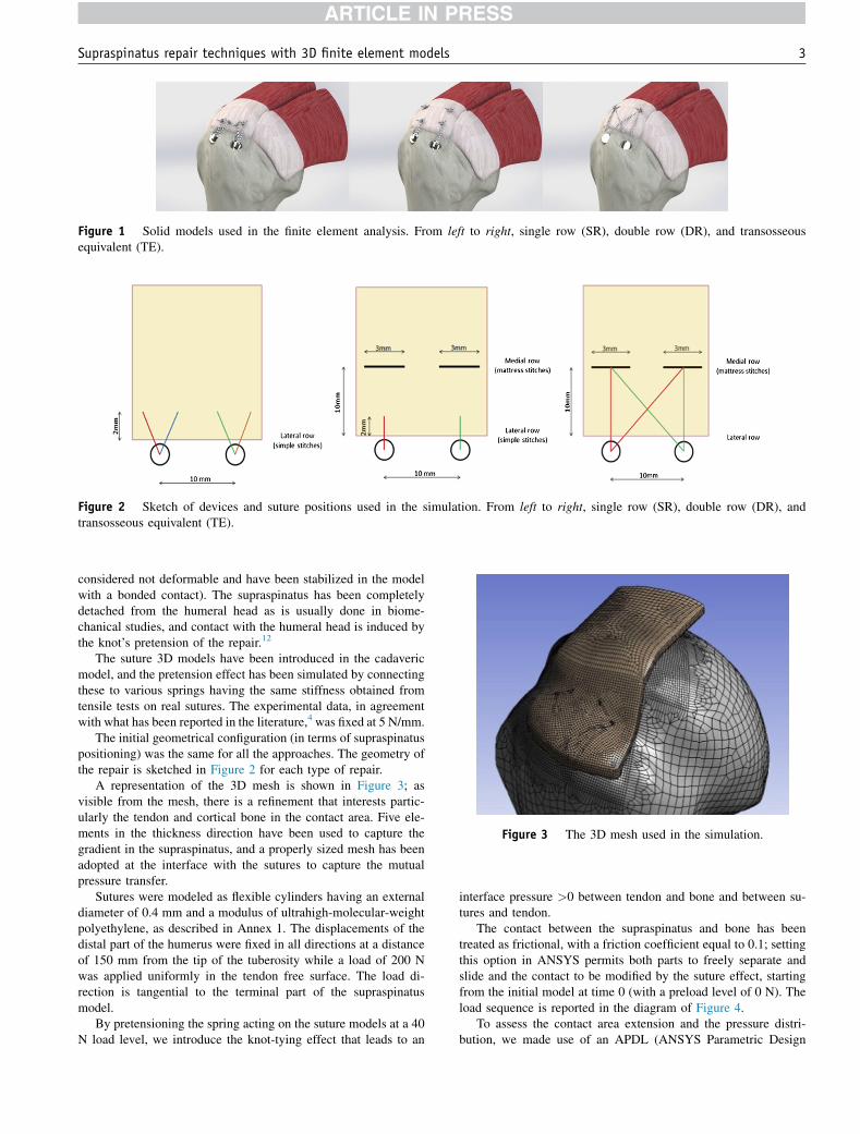
Figure 1 Solid models used in the finite element analysis. From left to right, single row (SR), double row (DR), and transosseousequivalent (TE).
Figure 2 Sketch of devices and suture positions used in the simulation. From left to right, single row (SR), double row (DR), andtransosseous equivalent (TE).
Figure 3 The 3D mesh used in the simulation.
Supraspinatus repair techniques with 3D finite element models 3
considered not deformable and have been stabilized in the modelwith a bonded contact). The supraspinatus has been completelydetached from the humeral head as is usually done in biome-chanical studies, and contact with the humeral head is induced bythe knot’s pretension of the repair.12
The suture 3D models have been introduced in the cadavericmodel, and the pretension effect has been simulated by connectingthese to various springs having the same stiffness obtained fromtensile tests on real sutures. The experimental data, in agreementwith what has been reported in the literature,4 was fixed at 5 N/mm.
The initial geometrical configuration (in terms of supraspinatuspositioning) was the same for all the approaches. The geometry ofthe repair is sketched in Figure 2 for each type of repair.
A representation of the 3D mesh is shown in Figure 3; asvisible from the mesh, there is a refinement that interests partic-ularly the tendon and cortical bone in the contact area. Five ele-ments in the thickness direction have been used to capture thegradient in the supraspinatus, and a properly sized mesh has beenadopted at the interface with the sutures to capture the mutualpressure transfer.
Sutures were modeled as flexible cylinders having an externaldiameter of 0.4 mm and a modulus of ultrahigh-molecular-weightpolyethylene, as described in Annex 1. The displacements of thedistal part of the humerus were fixed in all directions at a distanceof 150 mm from the tip of the tuberosity while a load of 200 Nwas applied uniformly in the tendon free surface. The load di-rection is tangential to the terminal part of the supraspinatusmodel.
By pretensioning the spring acting on the suture models at a 40N load level, we introduce the knot-tying effect that leads to an
interface pressure >0 between tendon and bone and between su-tures and tendon.
The contact between the supraspinatus and bone has beentreated as frictional, with a friction coefficient equal to 0.1; settingthis option in ANSYS permits both parts to freely separate andslide and the contact to be modified by the suture effect, startingfrom the initial model at time 0 (with a preload level of 0 N). Theload sequence is reported in the diagram of Figure 4.
To assess the contact area extension and the pressure distri-bution, we made use of an APDL (ANSYS Parametric Design

Figure 4 Load history adopted in the model.
Table II Evaluated contact areas of the various techniques
Repair method Repairarea (mm2)
Contact areawith a positivepressure (mm2)
Transosseous equivalent(4 anchors, 2 screwed and2 impacted laterally)
103 42
Single row 35 15.9Double row 87 26.8
4 M. Mantovani et al.
Language) macro script; a threshold pressure level of0.0001 MPa was adopted when the contact area was computed.The maximum accepted interpenetration between bodies in thecontact area is 0.001 mm. The surface considered by the macroand computed as the contact area consists only of the realtendon-bone interface, excluding the fixing device volume. Attime 0 between tendon and bone, a geometrical gap of 0.05 mmwas created. This gap was eliminated when the spring was pre-tensioned, simulating knot-tying action. Once the external load isapplied, the initial contact area can change because of the lack ofa counteracting downward pressure able to guarantee the stabilityof the initial contact.
The pretension forces, acting on the springs connected to thevarious sutures, were evaluated on the basis of the pressuremeasured by Tuoheti at al.30 The different models have beenevaluated from a geometrical standpoint, and we measured whatwe named the repair area, which is the area with a positive contactpressure greater than the threshold value.
Results
Table II reports the real active repair area, which excludesthe presence of synthetic material (the typical anchordiameter widely used in in vivo and ex vivo study spansbetween 5 and 6 mm) over which the attachment is notpossible.
The TE approach had a wider positive contact area. TheSR technique produced by far the lowest footprint coveragecompared with the other techniques. The DR techniqueprovides an increase of the positive contact area equal to69%, whereas the TE technique gives 164% more incomparison to the SR technique.
The area reported in the column ‘‘repair area’’ probablyunderestimates the real value, but the value reported in thelast column represents the element area sum that displays apositive value of the contact pressure. By the macrodescribed before, it is possible also to filter these data,excluding very low values (that cannot be considered ofreal effectiveness in a dynamic environment to prevent thetendon from sliding) and spurious peaks, which are morerelated to the model used instead of having a real physicalmeaning.
Figure 5 shows the representation of the contact area inthe various constructs. What appears evident is the effect ofthe suture bridge configuration on the final computation ofthe contact area. It is evident how a different suture layoutcan significantly vary the final extension of the contact andthe residual tension in the sutures, having a direct effect onthe sliding resistance (Fig. 6).
Discussion
In this study, we presented a finite element method as analternative to laboratory tests to compare various repairconfigurations. Even if the absolute values require a moreextensive experimental validation (see Annex 1 forencouraging preliminary experimental results), we couldconsider this comparative approach a flexible tool that canbe used to define the repair strategy supported by the bio-logic and mechanical factors that increase the probability ofhaving an intact construct.
Previously reported findings12,14,27,28,33 support finiteelement analysis as a promising tool to evaluate and tocompare various repair configurations in an easy, fast, andflexible way. Indeed, mechanical factors are at the basis of abiologic healing process (mechanical stability, pressuredistribution, contact area, reduction of local stress peaks).
In this study, biologic factors were not considered. Theproblem was addressed from a mechanical standpoint, and

Figure 5 Qualitative maps of the supraspinatus-bone contact layout; orange represents the area in contact with a positive appliedpressure. The free surfaces are in yellow, and the absence of any contact (device insertion areas) is shown in blue. Upper left, single row(SR); upper right, double row (DR); lower left, transosseous equivalent (TE).
Figure 6 Direct comparison of how a ‘‘dead area’’ (left side, evidenced by the red circle) is transformed in a compressive area throughthe use of a bridging configuration (right side, evidenced by the red circle).
Supraspinatus repair techniques with 3D finite element models 5
the configurations that maximize some geometrical andmechanical factors considered the basis of the healingprocess were discovered. These factors could be identifiedas area of contact, pressure and pressure distribution overthe contact, avoidance of local peak stress, and reduction ofthe tension over the repair. Milano et al19 have interestinglydemonstrated how excess tension applied over the repaircan significantly impair the biomechanical results. Thebiologic relation between applied pressure at the soft tis-sue–bone interface and the integrity of the repair has beendemonstrated.11
Several studies evaluated repair integrity, which weconsider of importance,11,19,29 such as Duquin et al,11 whocompared mechanical stability and repair integrity.
Many papers have compared SR and DR techniques interms of clinical outcomes, also looking at biomechan-ical and anatomic constructs.5,7,10,11,31 Data collected inour study suggest how the SR approach gives severalhigh-stress peaks in the areas close to the anchor’s po-sition; these pressures decrease sharply in the interanchorspace.
Our study follows previously reported trends,2,6,18-21,23,24
and highlights important aspects of repair techniques. Su-ture bridging between the various anchors or tunnels (in thecase of a transosseous approach) appears to be essential toincrease contact area. Suture bridges are effective not onlyfor their load sharing effect that reduces local peaks, butalso to make a ‘‘dead area’’ (defined as the footprint area

6 M. Mantovani et al.
between anchors that in some repair configurations presentsa zero contact pressure) active in the repair zone.
Another interesting finding is the effect of humeral headshape on contact asymmetry, as it is evident that footprintshape strongly influences contact pressure. Reshaping bydecortication will significantly increase compression intransosseous techniques, and maintain tight contact be-tween soft tissue and bone. A stable construct can enlargethe contact pressure and normalize pressure distribution,which may help keep the repair intact. Our proposedmethod may maximize footprint area coverage to enhancerepair integrity.
Following the guidelines provided by Viceconti et al,32
we are aware of the approximations introduced in thismodel. However, the purpose of our study was to comparethe efficacy of different repair techniques, and we do notfeel the simplifications biased our conclusions.
There are limitations to this study which wouldrequire validating the results in an experimental setup;however, comparing similar results in the literature, oursfollow the data trends, but the results are extremelydispersed.2,6,18,20,25
Our approach allows assessment of multiple variables,and seems promising. Dar8 reported that statistical methodsshould also be implemented for a more comprehensivecomparison of various techniques.
Conclusion
Our study confirms that DR and TE repairs lead to anincrease of the contact area and to a better distribution ofthe pressure coverage. Although the finite elementmethod is a theoretic one, the approach we presentedcould be a valid tool to predict and reproduce differentconfigurations and to infer conclusions concerningdifferent repair approaches. Further biomechanicalstudies are required to compare the repair techniques inthis study.
Disclaimer
Pietro Garofalo is employed as Product Manager at NCSLab Srl (Carpi, Modena, Italy).
Matteo Mantovani is Technical Director at NCS LabSrl (Carpi, Modena, Italy).
The other authors, their immediate families, and anyresearch foundations with which they are affiliated havenot received any financial payments or other benefitsfrom any commercial entity related to the subject of thisarticle.
Supplementary data
Supplementary data related to this article can be found athttp://dx.doi.org/10.1016/j.jse.2015.09.002.
References
1. Ahmad CS, Stewart AM, Izquierdo R, Bigliani LU. Tendon-bone
interface motion in transosseous suture and suture anchor rotator cuff
repair techniques. Am J Sports Med 2004;33:1667-71. http://dx.doi.
org/10.1177/0363546505278252
2. Apreleva M, €Ozbaydar M, Fitzgibbons PG, Warner JJ. Rotator cuff
tears: the effect of the reconstruction method on three dimensional site
area. Arthroscopy 2002;18:519-26. http://dx.doi.org/10.1053/jars.
2002.32930
3. Baums MH, Buchhorn GH, Spahn G, Poppendieck B, Schultz W,
Klinger HM. Biomechanical characteristics of single-row repair in
comparison to double-row repair with consideration of the suture
configuration and suturematerial. Knee Surg Sports Traumatol Arthrosc
2008;16:1052-60. http://dx.doi.org/10.1007/s00167-008-0590-2
4. Bisson LJ, Manohar LM, Wilkins RD, Gurske-Deperio J,
Ehrensberger MT. Influence of suture material on the biomechanical
behavior of suture-tendon specimens. A controlled study in bovine
rotator cuff. Am J Sports Med 2008;36:907-12. http://dx.doi.org/10.
1177/0363546508314793
5. Boileau P, Brassart N, Watkinson DJ, Carles M, Hatzidakis AM,
Krishnan SG. Arthroscopic repair of full-thickness tears of the
supraspinatus: does the tendon really heal? J Bone Joint Surg Am
2005;87:1229-40. http://dx.doi.org/10.2106/jbjs.d.02035
6. Brady PC, Arrigoni P, Burkhart SS. Evaluation of residual rotator cuff
defects after in vivo single- versus double-row rotator cuff repairs.
Arthroscopy 2006;22:1070-5. http://dx.doi.org/10.1016/j.arthro.2006.
05.007
7. Charousset C, Grimberg J, Duranthon LD, Bellaiche L, Petrover D.
Can a double-row anchorage technique improve tendon healing in
arthroscopic rotator cuff repair? A prospective, nonrandomized,
comparative study of double-row and single-row anchorage techniques
with computed tomographic arthrography tendon healing assessment.
Am J Sports Med 2007;35:1247-53. http://dx.doi.org/10.1177/
0363546507301661
8. Dar FH, Meakin JR, Aspden RM. Statistical methods in finite element
analysis. J Biomech 2002;35:1155-61. http://dx.doi.org/10.1016/
S0021-9290(02)00085-4
9. Denard PJ, Burkhart SS. The evolution of suture anchors in arthro-
scopic rotator cuff repair. Arthroscopy 2013;29:1589-95. http://dx.doi.
org/10.1016/j.arthro.2013.05.011
10. Dines JS, Bedi A, ElAttrache NS, Dines DM. Single-row versus
double-row rotator cuff repair: techniques and outcomes. J Am Acad
Orthop Surg 2010;18:83-93.
11. Duquin TR, Buyea C, Bisson LJ. Which method of rotator cuff repair
leads to the highest of structural healing? A systematic review. Am J
Sports Med 2010;38:835-41. http://dx.doi.org/10.1177/
0363546509359679
12. Funakoshi T, Suenaga N, Sano H, Oizumi N, Minami A. In vitro and
finite element analysis of a novel rotator cuff fixation technique. J
Shoulder Elbow Surg 2008;17:986-92. http://dx.doi.org/10.1016/j.jse.
2008.06.002
13. Gerber C, Schneeberger AG, Beck M, Schlegel U. Mechanical
strength of repairs of the rotator cuff. Bone Joint Surg Br 1994;76:
371-80.
14. Inoue A, Chosa E, Goto K, Tajima N. Nonlinear stress analysis of the
supraspinatus tendon using three-dimensional finite element analysis.
Supraspinatus repair techniques with 3D finite element models 7
Knee Surg Sports Traumatol Arthrosc 2012;21:1151-7. http://dx.doi.
org/10.1007/s00167-012-2008-4
15. Lee TQ. Current biomechanical concepts for rotator cuff repair. Clin
Orthop Surg 2013;5:89-97. http://dx.doi.org/10.4055/cios.2013.5.2.89
16. Levy JC, Everding NG, Frankle MA, Keppler LJ. Accuracy of patient-
specific guided glenoid baseplate positioning for reverse shoulder
arthroplasty. J Shoulder Elbow Surg 2014;23:1563-7. http://dx.doi.org/
10.1016/j.jse.2014.01.051
17. Mall NA, Lee AS, Chahal J, Van Thiel GS, Romeo AA, Verma NN,
et al. Transosseous-equivalent rotator cuff repair: a systematic re-
view on the biomechanical importance of tying the medial row.
Arthroscopy 2013;29:377-86. http://dx.doi.org/10.1016/j.arthro.
2012.11.008
18. Meier SW, Meier JD. Rotator cuff repair: the effect of double-row
fixation on three-dimensional repair site. J Shoulder Elbow Surg
2006;15:691-6. http://dx.doi.org/10.1016/j.jse.2006.03.004
19. Milano G, Grasso A, Zarelli D, Deriu L, Cillo M, Fabbriciani C.
Comparison between single-row and double-row rotator cuff
repair: a biomechanical study. Knee Surg Sports Traumatol
Arthrosc 2007;16:75-80. http://dx.doi.org/10.1007/s00167-007-
0382-0
20. Nho SJ, Slabaugh MA, Seroyer ST, Grumet RC, Wilson JB,
Verma NN, et al. Does the literature support double-row suture anchor
fixation for arthroscopic rotator cuff repair? A systematic review
comparing double-row and single-row suture anchor configuration.
Arthroscopy 2009;25:1319-28. http://dx.doi.org/10.1016/j.arthro.
2009.02.005
21. Ostrander RV 3rd, McKinney BI. Evaluation of footprint contact area
and pressure using a triple-row modification of the suture-bridge
technique for rotator cuff repair. J Shoulder Elbow Surg 2012;21:
1406-12. http://dx.doi.org/10.1016/j.jse.2011.10.027
22. Ozbaydar M, Elhassan B, Esenyel C, Atalar A, Bozdag E,
Sunbuloglu E, et al. A comparison of single- versus double-row suture
anchor techniques in a simulated repair of the rotator cuff: an exper-
imental study in rabbits. J Bone Joint Surg Br 2008;90:1386-91. http://
dx.doi.org/10.1302/0301-620x.90b10.20862
23. Park MC, Elattrache NS, Ahmad CS, Tibone JE. ‘‘Transosseous-
equivalent’’ rotator cuff repair technique. Arthroscopy 2006;22:1360.
e1-e5. http://dx.doi.org/10.1016/j.arthro.2006.07.017
24. Park MC, ElAttrache NS, Tibone JE, Ahmad CS, Jun BJ, Lee TQ. Part
I: footprint contact characteristics for a transosseous-equivalent rotator
cuff repair technique compared with a double-row repair technique. J
Shoulder Elbow Surg 2007;16:461-8. http://dx.doi.org/10.1016/j.jse.
2006.09.010
25. Park MC, Tibone JE, ElAttrache NS, Ahmad CS, Jun BJ, Lee TQ. Part
II: biomechanical assessment for a footprint-restoring transosseous-
equivalent rotator cuff repair technique compared with a double-row
repair technique. J Shoulder Elbow Surg 2007;16:469-76. http://dx.
doi.org/10.1016/j.jse.2006.09.011
26. Pauly S, Gerhardt C, Chen J, Scheibel M. Single versus double-
row repair of the rotator cuff. Knee Surg Sports Traumatol
Arthrosc 2010;18:1718-29. http://dx.doi.org/10.1007/s00167-010-
1245-7
27. Sano H, Takahashi A, Chiba D, Hatta T, Yamamoto N, Itoi E. Stress
distribution inside bone after suture anchor insertion: simulation using
a three-dimensional finite element method. Knee Surg Sports Trau-
matol Arthrosc 2012;21:1777-82. http://dx.doi.org/10.1007/s00167-
012-2060-0
28. Sano H, Wakabayashi I, Itoi E. Stress distribution in the supraspinatus
tendon with partial-thickness tears: an analysis using two-dimensional
finite element model. J Shoulder Elbow Surg 2006;15:100-5. http://dx.
doi.org/10.1016/j.jse.2005.04.003
29. Trappey GJ 4th, Gartsman GM. A systematic review of the clinical
outcomes of single row versus double row rotator cuff repairs. J
Shoulder Elbow Surg 2011;20:S14-9. http://dx.doi.org/10.1016/j.jse.
2010.12.001
30. Tuoheti Y, Itoi E, Yamamoto N, Seki N, Abe H, Minagawa H, et al.
Contact area, contact pressure, and contact patterns of the tendon-bone
interface after rotator cuff repair. Am J Sports Med 2005;33:1869-74.
http://dx.doi.org/10.1177/0363546505278256
31. Van der Zwaal P, Thomassen BJ, Nieuwenhuijse MJ, Lindenburg R,
Swen JW, Van Arkel ER. Clinical outcome in all-arthroscopic versus
mini-open rotator cuff repair in small to medium-sized tears: a ran-
domized controlled trial in 100 patients with 1-year follow-up.
Arthroscopy 2013;29:266-73. http://dx.doi.org/10.1016/j.arthro.2012.
08.022
32. Viceconti M, Olsen S, Burton K. Extracting clinically relevant
data from finite element simulations. Clin Biomech (Bristol,
Avon) 2005;20:451-4. http://dx.doi.org/10.1016/j.clinbiomech.
2005.01.010
33. Wakabayashi I, Itoi E, Sano H, Shibuya Y, Sashi R, Minagawa H, et al.
Mechanical environment of the supraspinatus tendon: a two-
dimensional finite element model analysis. J Shoulder Elbow Surg
2003;12:612-7. http://dx.doi.org/10.1016/S1058-2746(03)00214–3