96bronco
DESCRIPTION
TRANSCRIPT
[PI00300(B )04/95]
thirty-six pica chart:0021233-C
File:ltpib.exUpdate:Fri Jun 9 15:32:42 1995

*[PI00800( ALL)05/95]
thirty-six pica chart:
File:ltpib.exUpdate:Fri Jun 9 15:32:42 1995

*[PI02300( ALL)05/95]
Table of Contents
Introductory Information ............................... 1
Safety Restraints ............................................ 11
Starting Your Bronco .................................... 59
Warning Lights and Gauges ....................... 73
Instrument Panel Controls .......................... 89
Steering Column Controls ........................ 105
Features .......................................................... 119
Electronic Sound Systems ......................... 149
Driving Your Bronco .................................. 175
Roadside Emergencies ................................ 237
Customer Assistance ................................... 255
Accessories .................................................... 267
Servicing Your Bronco ............................... 275
Quick Index .................................................. 355
Index ............................................................... 363
File:ltpib.exUpdate:Fri Jun 9 15:32:42 1995

1
Introductory Information
*[IN00300( ALL)04/95] Ford’s Commitment to You
*[IN00400( ALL)04/95] At Ford Motor Company, excellence is thecontinuous commitment to achieve the bestresult possible. It is dedication to learning whatyou want, determination to develop the rightconcept, and execution of that concept with care,precision, and attention to detail. In short,excellence means being the standard by whichothers are judged.
*[IN00500( ALL)04/95] Our Guiding Principles
*[IN00600( ALL)04/95] ❑Quality comes first. For your satisfaction, thequality of our products and services must beour number one priority.
*[IN00700( ALL)04/95] ❑You are the focus of everything we do. Ourwork must be done with you in mind,providing better products and services thanour competition.
*[IN00750( ALL)04/95] ❑Continuous improvement is essential to oursuccess. We must strive for excellence ineverything we do: in our products — in theirsafety and value — and in our services, ourhuman relations, our competitiveness, andour profitability.
*[IN00800( ALL)04/95] ❑Employee involvement is our way of life.We are a team. We must treat one anotherwith trust and respect.
*[IN00900( ALL)04/95] ❑Dealers and suppliers are our partners. Wemust maintain mutually beneficialrelationships with dealers, suppliers, and ourother business associates.
File:ltinb.exUpdate:Fri Jun 9 15:32:32 1995

2
*[IN01000( ALL)04/95] ❑ Integrity is never compromised. Our conductworldwide must be pursued in a manner thatis socially responsible and commands respectfor its integrity and for its positivecontributions to society.
*[IN01100( ALL)04/95] Things to Know About UsingThis Guide
*[IN01112(BEF )04/95] Congratulations on the purchase of your newvehicle. This guide has information about theequipment and the options for your new vehicle.You may not have bought all of the optionsavailable to you. If you do not know whichinformation applies to your vehicle, talk to yourdealer.
*[IN01137(BEF )04/95] This guide describes equipment and givesspecifications for equipment that was in effectwhen this guide was approved for printing. Fordmay discontinue models or change specificationsor design without any notice and withoutincurring obligation.
*[IN01162( ALL)05/95] NOTES and WARNINGS
*[IN01164( ALL)05/95] NOTES give you additional information aboutthe subject matter you are referencing.
*[IN01166( ALL)05/95] WARNINGS remind you to be especially carefulin those areas where carelessness can causedamage to your vehicle or personal injury toyourself, your passengers or other people. Pleaseread all WARNINGS carefully.
*[IN01168( ALL)05/95] RWARNING
File:ltinb.exUpdate:Fri Jun 9 15:32:32 1995

3
*[IN01600( ALL)04/95] Finding Information in This Guide
[IN01700( ALL)04/95] After you have read this guide once, you willprobably return to it when you have a specificquestion or need additional information. To helpyou find specific information quickly, you canuse the table of contents or the index.
*[IN01800(BEF )05/95] The Quick Index at the end of the bookprovides a page number following each itemwhich indicates where detailed information canbe found.
*[IN02000( ALL)05/95] This guide has a table of contents at thebeginning of the book to show chapter titles.
*[IN02100( ALL)04/95] To use the Index, turn to the back of the bookand search in the alphabetical listing for theword that best describes the information youneed. If the word you chose is not listed, thinkof other related words and look them up. Wehave designed the Index so that you can findinformation under a technical term.
%*[IN02200( ALL)04/95] Canadian Owners — French Version
*[IN02300( ALL)05/95] French Owner Guides can be obtained from yourdealer or by writing to Ford Motor Company ofCanada, Limited, Service Publications, P.O. Box1580, Station B, Mississauga, Ontario L4Y 4G3.
*[IN02400( ALL)04/95] Your Maintenance Schedule andRecord Booklet
*[IN02500( ALL)03/95] The Maintenance Schedule and Record booklet liststhe services that are most important for keepingyour vehicle in good condition. A record log isalso provided to help you keep track of allservices performed.
File:ltinb.exUpdate:Fri Jun 9 15:32:32 1995

4
%*[IN02600( ALL)01/95] About the Warranties
*[IN02700(BEF )04/95] Your vehicle is covered by three types ofwarranties: Basic Vehicle Warranty, ExtendedWarranties on certain parts, and EmissionsWarranties.
%*[IN03100( ALL)03/95] Read your Warranty Information Booklet carefullyto find out about your vehicle’s warranties andyour basic rights and responsibilities.
*[IN03250( ALL)03/95] If you lose your Warranty Information Booklet, youcan get a new one free of charge. Contact anyFord or Lincoln-Mercury dealer, or refer to theaddresses and phone numbers on the first pageof this owner guide.
%*[IN04000( ALL)01/95] Buying a Ford Extended Service Plan
*[IN04100( ALL)01/94] If you bought your vehicle in the U.S., you canbuy a Ford Extended Service Plan for yourvehicle. This optional contract provides serviceprotection for a longer period of time than thebasic warranty that comes with your vehicle.
*[IN04200( ALL)01/95] You do not have to buy this option when youbuy your vehicle. However, your option topurchase the Ford Extended Service Plan runsout after 18 months or 18,000 miles. See yourdealer for more details about the Ford ExtendedService Plan.
*[IN04250( ALL)01/95] If you purchased a Canadian vehicle and did nottake advantage of the Ford Extended ServicePlan at the time of purchase, you may still beeligible. See your dealer for the details.
File:ltinb.exUpdate:Fri Jun 9 15:32:32 1995
5
*[IN04650(B M)06/92] Special Notice
*[IN04700(B )11/89] NOTICE TO OWNERS OFUTILITY-TYPE VEHICLES
*[IN04810(B )11/89] As with other vehicles of this type, failure tooperate this vehicle correctly may result in lossof control or an accident. Be sure to read theAdditional Special Driving Instructions for UtilityVehicles in this book and the special supplementincluded with four-wheel drive vehicles entitled4-Wheeling with Ford.
*[IN04850(B )03/95] AMBULANCE PACKAGES
*[IN04875(B )03/95] RWARNING
Do not use this vehicle as an ambulance.
%*[IN05100( ALL)05/95] Your Vehicle IdentificationNumber (VIN)
*[IN05200( ALL)05/95] Your Vehicle Identification Number (VIN) is thesame as the warranty number that appears onyour owner card. You should include thisnumber any time you write to Ford MotorCompany about your vehicle.
*[IN05300(BEF )05/95] The Vehicle Identification Number is attached toyour vehicle in the following places:
*[IN05400(BEF )05/95] ❑on the metal tag attached to the top of theinstrument panel on the driver’s side — youcan see the tag by looking through thewindshield from outside your vehicle.
File:ltinb.exUpdate:Fri Jun 9 15:32:32 1995
6
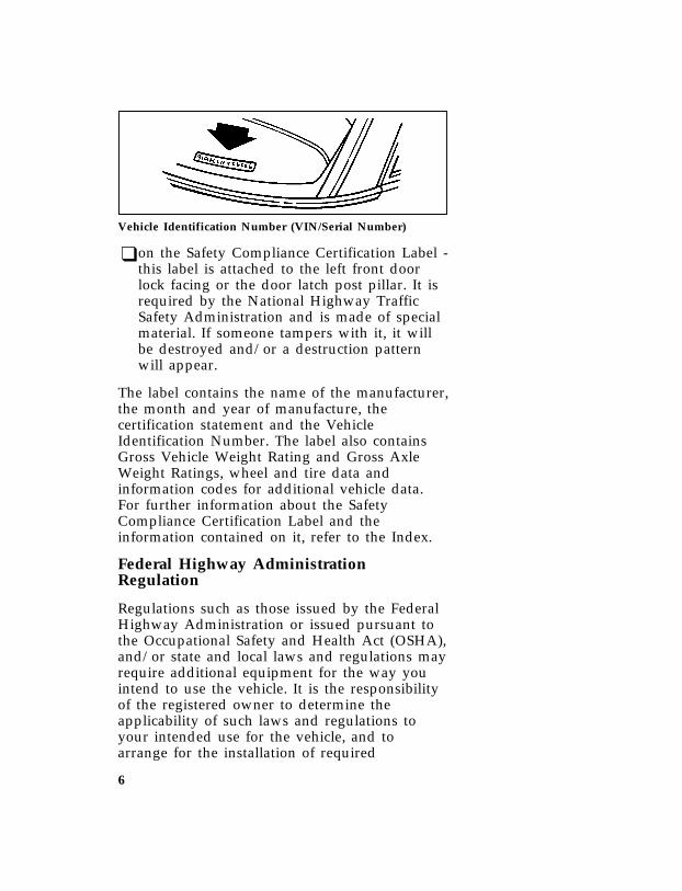
*[IN05450(BEF )10/89]
one inch art:0010558-A
Vehicle Identification Number (VIN/Serial Number)
%*[IN05500(BEF )05/95] ❑on the Safety Compliance Certification Label -this label is attached to the left front doorlock facing or the door latch post pillar. It isrequired by the National Highway TrafficSafety Administration and is made of specialmaterial. If someone tampers with it, it willbe destroyed and/or a destruction patternwill appear.
*[IN05515( ALL)04/94] The label contains the name of the manufacturer,the month and year of manufacture, thecertification statement and the VehicleIdentification Number. The label also containsGross Vehicle Weight Rating and Gross AxleWeight Ratings, wheel and tire data andinformation codes for additional vehicle data.For further information about the SafetyCompliance Certification Label and theinformation contained on it, refer to the Index.
*[IN05545( ALL)04/95] Federal Highway AdministrationRegulation
*[IN05560( ALL)04/95] Regulations such as those issued by the FederalHighway Administration or issued pursuant tothe Occupational Safety and Health Act (OSHA),and/or state and local laws and regulations mayrequire additional equipment for the way youintend to use the vehicle. It is the responsibilityof the registered owner to determine theapplicability of such laws and regulations toyour intended use for the vehicle, and toarrange for the installation of required
File:ltinb.exUpdate:Fri Jun 9 15:32:32 1995

7
equipment. Your Ford dealer has informationabout the availability of many items ofequipment which may be ordered for yourvehicle.
*[IN06000( ALL)01/95] Breaking Your Vehicle In
*[IN06100( ALL)03/95] Your new vehicle goes through an adjustment orbreak-in period during the first 1,000 miles(1,600 km) that you drive it. During the break-inperiod, you need to pay careful attention to howyou drive your vehicle.
%*[IN06300( ALL)01/95] ❑Avoid sudden stops. Because your vehiclehas new brake linings, you should take thesesteps:
*[IN06400( ALL)01/95] — Watch traffic carefully so that you cananticipate when to stop.
*[IN06500( ALL)01/95] — Begin braking well in advance.
*[IN06600( ALL)01/95] — Apply the brakes gradually.
*[IN06700( ALL)01/95] The break-in period for new brake liningslasts for 100 miles (160 km) of city driving or1,000 miles (1,600 km) of highway driving.
*[IN06750( ALL)12/93] ❑Wheel lug nuts must be retightened to propertorque specifications at 500 miles/800 km ofnew vehicle operation. Proper torquespecifications are provided in this guide. Alsoretighten to proper torque specification at 500miles/800 km after any wheel change or anyother time the wheel lug nuts have beenloosened.
%*[IN06800(BEF )01/95] ❑Use only the type of engine oil that Fordrecommends. See Engine oil recommendationsin the Index. Do not use special “break-in”oils.
File:ltinb.exUpdate:Fri Jun 9 15:32:32 1995

8
%*[IN07100(BEF )04/95] Cleaning the Outside of YourVehicle
%*[IN07200(BEF )04/95] Washing and Polishing Your Vehicle
*[IN07300(BEF )04/95] Wash the outside of your vehicle, including theunderside, with a mild detergent.
*[IN07400(BEF )04/95] DO NOT:
*[IN07500(BEF )04/95] ❑Wash your vehicle with hot water
*[IN07600(BEF )04/95] ❑Wash your vehicle while it sits in directsunlight
*[IN07700(BEF )04/95] ❑Wash your vehicle while the body is hot
*[IN07800(BEF )05/95] Pollen, bird droppings and tree sap can damagethe paint, especially in hot weather. Wash yourvehicle as often as necessary to keep it clean.
*[IN07900(BEF )05/95] Take similar precautions if your vehicle isexposed to chemical industrial fallout.
*[IN08000(BE )05/95] Paint damage resulting from fallout is notrelated to a defect in paint materials orworkmanship and therefore is not covered bywarranty. Ford, however, believes that continualimprovement in customer satisfaction is a highpriority. For this reason, Ford has authorized itsdealers to repair, at no charge to the owner, thesurfaces of new vehicles damaged byenvironmental fallout within 12 months or 12,000miles (20,000 km) of purchase, whichever comesfirst. Customers may be required to bring theirvehicle in for inspection by a Fordrepresentative.
*[IN08100(BEF )04/95] Polish your vehicle to remove harmful depositsand protect the finish.
File:ltinb.exUpdate:Fri Jun 9 15:32:32 1995

9
%*[IN08200(BEF )04/95] Cleaning Chrome and Aluminum Parts
*[IN08300(BEF )04/95] Wash chrome and aluminum parts with thesame detergent you use to wash the vehiclebody, such as Ford Premium Car WashConcentrate. You can use Ford Extra StrengthTar and Road Oil Remover or equivalent toclean grease, oil, and tar from chrome-platedparts, including wheelcovers, aluminum wheels,bumpers, or anodized aluminum parts.
%*[IN08400(BEF )04/95] Cleaning Plastic Parts
*[IN08500(BEF )04/95] Some of your vehicle’s exterior trim parts areplastic. Clean with a tar and road oil remover ifnecessary. Use a vinyl cleaner for routinecleaning.
*[IN08600(BEF )04/95] Do not clean plastic parts with thinners, solventsor petroleum-based cleaners.
%*[IN08700(BEF )04/95] If you have your vehicle rustproofed, removeoversprayed rustproofing with a tar and road oilremover. If rustproofing is not removed fromplastic and rubber parts, it can causedeterioration.
File:ltinb.exUpdate:Fri Jun 9 15:32:32 1995

11
Safety Restraints
*[SR00500(BEF )04/95] Important Safety Belt Information
*[SR00600(BEF )03/95] The use of safety belts helps to restrain you andyour passengers in case of a collision. In moststates and in Canada the law requires their use.
*[SR00700(BEF )01/95] Safety belts provide best restraint when:
*[SR00800(BEF )01/95] ❑ the seatback is upright
*[SR00900(BEF )01/95] ❑ the occupant is sitting upright (not slouched)
*[SR01000(BEF )01/95] ❑ the lap belt is snug and low on the hips
*[SR01100(BEF )01/95] ❑ the shoulder belt is snug against the chest
*[SR01200(BEF )01/95] ❑ the knees are straight forward
*[SR02000(BEF )05/95] To help you remember to fasten your safety belt,a warning light may come on and a chime maysound. See Safety Belt Warning Light and Chime inthe Warning Lights and Gauges chapter.
*[SR02100(BEF )01/95] See the following sections in this chapter fordirections on how to properly use these safetybelts. Also see Safety Restraints for Children in thischapter for special instructions about usingsafety belts for children.
%*[SR02200(BEF )05/95] RWARNING
Make sure that you and your passengerswear safety belts. Always drive and ridewith your seatback upright and the lapbelt snug and low across the hips.
File:ltsrb.exUpdate:Tue Jun 20 16:58:10 1995

12
*[SR02400(BEF )05/95] RWARNING
Passengers should not be allowed to ridein the cargo area. Persons not riding in aseat with a fastened seat belt are muchmore likely to suffer serious injury in acollision. Cargo should always be securedto prevent it from shifting and causingdamage to the vehicle or harm topassengers.
*[SR02500(BEF )05/95] RWARNING
Never let a passenger hold a child on hisor her lap while the vehicle is moving.The passenger cannot protect the childfrom injury in a collision.
*[SR02600(BEF )05/95] RWARNING
To reduce the risk of serious injury in acollision, children should always ride withthe seatback upright.
*[SR02800(BEF )03/95] RWARNING
Never wear the shoulder belt under thearm. Never swing it around the neck overthe inside shoulder. Never use a singlebelt for more than one person or acrossmore than one seating position. Eachseating position in your vehicle has aspecific safety belt assembly which ismade up of one buckle and one tonguethat are designed to be used as a pair.Failure to follow these precautions couldincrease the risk and/or severity of injuryin a collision.
File:ltsrb.exUpdate:Tue Jun 20 16:58:10 1995
13
*[SR02900(BEF )05/95] Lock the doors of your vehicle before driving tolessen the risk of the door coming open in acollision.
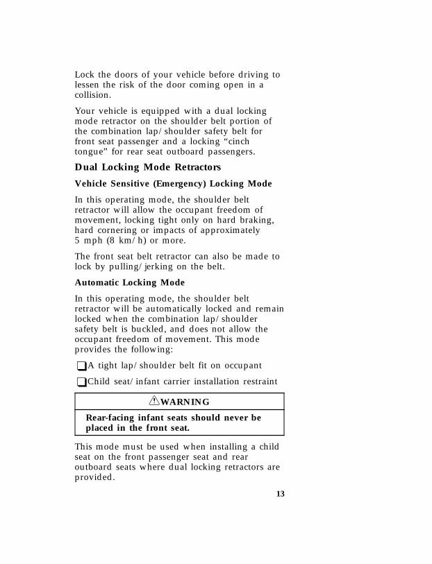
[SR02920(B )04/95] Your vehicle is equipped with a dual lockingmode retractor on the shoulder belt portion ofthe combination lap/shoulder safety belt forfront seat passenger and a locking “cinchtongue” for rear seat outboard passengers.
[SR02930(BEF )04/95] Dual Locking Mode Retractors
[SR02940(BEF )04/95] Vehicle Sensitive (Emergency) Locking Mode
[SR02950(BEF )04/95] In this operating mode, the shoulder beltretractor will allow the occupant freedom ofmovement, locking tight only on hard braking,hard cornering or impacts of approximately5 mph (8 km/h) or more.
[SR02960(BEF )04/95] The front seat belt retractor can also be made tolock by pulling/jerking on the belt.
[SR02970(BEF )04/95] Automatic Locking Mode
[SR02980(BEF )04/95] In this operating mode, the shoulder beltretractor will be automatically locked and remainlocked when the combination lap/shouldersafety belt is buckled, and does not allow theoccupant freedom of movement. This modeprovides the following:
[SR02990(BEF )04/95] ❑A tight lap/shoulder belt fit on occupant
[SR03000(BEF )04/95] ❑Child seat/infant carrier installation restraint
[SR03010(B F )04/95] RWARNING
Rear-facing infant seats should never beplaced in the front seat.
[SR03020(BEF )04/95] This mode must be used when installing a childseat on the front passenger seat and rearoutboard seats where dual locking retractors areprovided.
File:ltsrb.exUpdate:Tue Jun 20 16:58:10 1995

14
[SR03030(BEF )04/95] To switch the retractor from the “emergencylocking mode” to the “automatic locking mode,”perform the following steps:
[SR03040(BEF )04/95] 1. Buckle the lap/shoulder combination belt.
[SR03050(BEF )04/95] 2. Grasp the shoulder portion of the belt andpull downward until all of the belt isextracted, and when allowed to retract, aclicking sound will be heard. At this time,the belt retractor is in the “automatic lockingmode” (child restraint mode).
[SR03060(BEF )04/95] 3. A clicking sound will continue to be heardas the belt is allowed to retract. Thisindicates that the retractor is in the“automatic locking mode.”
[SR03070(BEF )04/95] NOTE: When the combination lap/shoulderbelt is unbuckled and allowed toretract completely, the retractor willswitch back to the vehicle sensitive(emergency) locking mode. See thedetailed instructions under Safety Seatsfor Children in this chapter.
[SR03080(B )04/95] Locking Cinch Tongue
[SR03085(B )04/95] The “locking cinch tongue” will slide up anddown the belt webbing when belt is in thestowed position or while putting seat belt on.When the “locking cinch tongue” of thelap/shoulder combination seat belt is latchedinto buckle, the “cinch tongue” will allow thelap portion to become shorter, but locks thewebbing in-place to restrict it from becominglonger.
[SR03090(B )04/95] Your vehicle is equipped with safety seat beltscontaining a “cinch tongue” at the rear outboardseating positions.
File:ltsrb.exUpdate:Tue Jun 20 16:58:10 1995
15
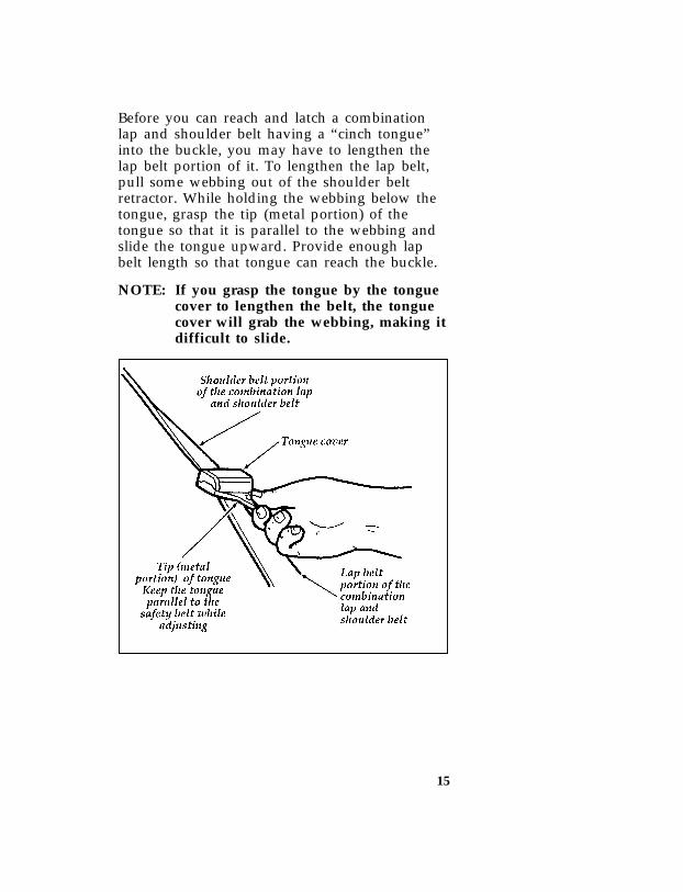
[SR03095(B )04/95] Before you can reach and latch a combinationlap and shoulder belt having a “cinch tongue”into the buckle, you may have to lengthen thelap belt portion of it. To lengthen the lap belt,pull some webbing out of the shoulder beltretractor. While holding the webbing below thetongue, grasp the tip (metal portion) of thetongue so that it is parallel to the webbing andslide the tongue upward. Provide enough lapbelt length so that tongue can reach the buckle.
[SR03100(B )04/95] NOTE: If you grasp the tongue by the tonguecover to lengthen the belt, the tonguecover will grab the webbing, making itdifficult to slide.
[SR03105(B )05/95]
half page art:0021501-A
File:ltsrb.exUpdate:Tue Jun 20 16:58:10 1995

16
[SR03110(B )04/95] To fasten a “cinch tongue,” pull the combinationlap and shoulder belt from the retractor so thatthe shoulder belt portion of the safety beltcrosses your shoulder and chest. Be sure the beltis not twisted. If the belt is twisted, remove thetwist. (For instructions on how to remove atwist, see the How to Untwist or Unjam a SafetyBelt Retractor section in this chapter.) Insert thebelt tongue into the proper buckle for yourseating position until you hear a snap and feel itlatch. Make sure the tongue is securely fastenedto the buckle by pulling on tongue. Adjust thelap belt portion of the safety belt by pulling upon the shoulder belt until the lap belt fits snuglyand as low as possible around your hips.
[SR03115(B )05/95]
half page art:0000841-B
Lab and shoulder belt fastened
File:ltsrb.exUpdate:Tue Jun 20 16:58:10 1995

17
*[SR03120(BEF )05/95] Combination Lap and ShoulderBelts
*[SR03125(BEF )05/95] While your vehicle is in motion, the combinationlap and shoulder belt adjusts to your movement.However, if you brake hard, corner hard or ifyour truck receives an impact of 5 mph(8 km/h) or more, the combination lap/shoulderbelt locks and helps reduce your forwardmovement. The front seat belt systems can alsobe made to lock by jerking on the shoulder belt.
*[SR03130(BEF )05/95] NOTE: The rear belts cannot be made to lockup by jerking on shoulder belt.
*[SR03135(BEF )05/95] After you get into your vehicle, close the doorand lock it. Then adjust the seat to the positionthat suits you best.
[SR03137(BEF )05/95] To fasten the belt
*[SR03140(BEF )05/95] Pull the combination lap/shoulder belt from theretractor so that the shoulder portion of the beltcrosses your shoulder and chest. Be sure the beltis not twisted. If it is, remove the twist. Insertthe belt tongue into the proper buckle until youhear a snap and feel it latch. Make sure thetongue is securely fastened to the buckle bypulling on tongue.
[SR03150(B )05/95]
one third page art:0020639-D
File:ltsrb.exUpdate:Tue Jun 20 16:58:10 1995

18
[SR03155(B )05/95]
7-1/2 pica art:0021500-A
*[SR03160(BEF )05/95] RWARNING
Use the shoulder belt on the outsideshoulder only. Never wear the shoulderbelt under the arm. Never swing it aroundthe neck over the inside shoulder. Neveruse a single belt for more than oneperson. Failure to follow these precautionscould increase the risk and/or severity ofinjury in a collision.
*[SR03165(BEF )05/95] To tighten the lap portion of the belt, pull up onthe shoulder belt until it fits you snugly. Thebelt should rest as low on your hips as possible.
[SR03185(BEF )05/95] Due to folding rear seats, sometimes the bucklesand tongues toward the center of the vehiclemay be hidden by the rear edge of the seatcushion. Pull them out so they will be accessible.
File:ltsrb.exUpdate:Tue Jun 20 16:58:10 1995

19
[SR03190(BEF )05/95] While you are fastened in the seat belt, thecombination lap and shoulder belt adjusts toyour movement. However, if you brake hard,turn hard, or if your vehicle receives an impactof 5 mph (8 km/h) or more, the lap andshoulder belt will become locked and helpreduce your forward movement.
%*[SR06800(BEF )05/95] Adjustable Lap Belts Without Retractors
[SR07100(B )05/95] On the center position of the front and rearthree-passenger bench seats you will find alap-belt without a retractor, but does have alocking adjustable tongue. Shorten this belt andfasten it to buckle when you are not using it. Tolengthen the belt, tip the tongue at a right angleto the belt and pull the belt over your lap untilthe tongue reaches the buckle.
[SR07400(BEF )05/95]
one third page art:0020638-C
Fastening occupant safety lap belts
[SR07500(BEF )04/95] To fasten the belt, pull the belt across your hipsand insert the tongue into the correct buckle onyour seat until you hear a snap and feel it latch.Make sure the buckle is securely fastened bypulling tongue.
File:ltsrb.exUpdate:Tue Jun 20 16:58:10 1995

20
*[SR07600(BEF )03/91] Adjust the belt so that it fits snugly and as lowas possible around the hips:
*[SR07700(BEF )02/95] ❑ If you need to lengthen the belt, unfasten itand repeat the procedure above.
*[SR07800(BEF )03/95] ❑ If you need to shorten the belt, pull on theloose end of the webbing.
[SR08500(BEF )05/95] To unfasten the belt:
[SR08525(BEF )05/95] 1. Push the release button on the buckle. Thisallows the tongue to unlatch from thebuckle.
[SR08600(B )05/95]
7-1/2 pica art:0020639-D
Unfastening the front outboard lap/shoulder belts
[SR08625(B )05/95]
7-1/2 pica art:0021500-A
Unfastening the rear outboard lap/shoulder belts
[SR08650(BEF )05/95] 2. While the belt retracts, guide the tongue toits stowed position. If you do not guide thetongue, it may strike you or part of thevehicle.
File:ltsrb.exUpdate:Tue Jun 20 16:58:10 1995

21
[SR08651(B )05/95] Instructions for securing child safety seats withcombination lap/shoulder safety belts having“cinch tongues” are provided later in thischapter.
*[SR08800(BEF )03/95] How to Untwist or Unjam a Safety BeltRetractor
*[SR08900(BEF )03/95] If you should jam the lap belt retractor byallowing the belt to retract when it is twisted,you can free the webbing with this procedure:
*[SR09000(BEF )03/95] 1. Pull on the belt with both hands to tighten iton the retractor spool.
*[SR09100(BEF )03/95] 2. Feed the belt back into the retractor until itis completely retracted. Repeat previous stepif necessary.
[SR09200(BEF )02/95] 3. Pull the belt out of the retractor as far as itwill go and untwist the belt or remove theobject that is jamming the belt. Let the beltretract.
*[SR09300(BEF )03/95] 4. Then, pull the belt out and let it retractseveral times to make sure that the beltworks properly.
File:ltsrb.exUpdate:Tue Jun 20 16:58:10 1995

22
[SR09505(BEF )05/95] Procedure to Correct a Twisted SafetyShoulder Belt at the “D” Ring (if soequipped) Front and/or Rear OutboardSeating Positions
[SR09507(BEF )05/95] NOTE: The restraint system shown in thefollowing figures may be different thanthe restraint system in your vehicle.However, use these figures and thisprocedure to correct a twisted safetyshoulder belt at any outboard seatingposition that has a “D” ring.
[SR09510(BEF )05/95]
half page art:0060598-C
File:ltsrb.exUpdate:Tue Jun 20 16:58:10 1995

23
[SR09515(BEF )05/95] 1. Grasp the belt webbing at the “D” ring. SeeFigure 2.
[SR09520(BEF )05/95]
half page art:0060599-D
[SR09525(BEF )05/95] 2. Rotate and fold the belt webbing over itselfas required to remove the twist.
[SR09527(BEF )05/95] 3. Feed the folded portion of the belt throughthe “D” ring.
[SR09530(BEF )05/95] 4. When completed, the safety belt should looklike Figure 3.
File:ltsrb.exUpdate:Tue Jun 20 16:58:10 1995

24
[SR09535(BEF )05/95]
half page art:0060600-D
%*[SR09600(BEF )05/95] Safety Belt Extension Assembly
*[SR09700(BEF )05/95] For some people, the safety belt may be tooshort even when it is fully extended. You canadd about eight inches (20 cm) to the belt lengthwith a safety belt extension assembly (partnumber 611C22). Safety belt extensions areavailable at no cost from your dealer.
*[SR09750(BEF )05/95] Use only extensions manufactured by the samesupplier as the safety belt. Manufactureridentification is located at the end of the webbingon the label. Also, use the safety belt extensiononly if the safety belt is too short for you whenfully extended. Do not use extension to change thefit of the shoulder belt across the torso.
*[SR09800(BEF )05/95] RWARNING
Failure to follow these instructions willaffect the performance of the safety beltsand increase the risk of personal injury.
File:ltsrb.exUpdate:Tue Jun 20 16:58:10 1995
25
%*[SR09900(BEF )05/95] Safety Belt Maintenance[SR10000(BEF )02/95] Check your safety belt system periodically to
make sure that it works properly and isn’tdamaged. If the webbing shows any wear, nicksor cuts, have it examined by a qualifiedtechnician to determine if replacement isnecessary. Always have your safety belt systemchecked after a collision by a qualifiedtechnician.
*[SR10200(BEF )05/95] All safety belt assemblies, including retractors,buckles, front seat belt buckle support assemblies(slide bar) (if so equipped), child safety seattether bracket assemblies (if so equipped), andattaching hardware, should be inspected afterany collision. Ford recommends that all safetybelt assemblies used in vehicles involved in acollision be replaced. However, if the collisionwas minor and a qualified technician finds thatthe belts do not show damage and continue tooperate properly, they do not need to bereplaced. Safety belt assemblies not in useduring a collision should also be inspected andreplaced if either damage or improper operationis noted.
%*[SR10210(BEF )05/95] Cleaning the Safety Belts
*[SR10220(BEF )05/95] Clean the safety belts with any mild soapsolution that is recommended for cleaningupholstery or carpets. Do not bleach or dye thebelt webbing because this may weaken it.
*[SR10300(BEF )04/95] Air Bag Supplemental RestraintSystem (SRS)
*[SR10400(B )03/94] Driver air bag
*[SR10500(B F )03/95] Your vehicle is equipped with a driver side airbag supplemental restraint system located in thesteering wheel and identified by the letters“SRS” in the center of the wheel.
File:ltsrb.exUpdate:Tue Jun 20 16:58:10 1995

26
*[SR10600(BEF )03/95] The driver air bag is a Supplemental RestraintSystem (SRS), provided in addition to the driverlap/shoulder belt, and is designed tosupplement the protection provided to aproperly belted driver in moderate to severefrontal collisions. The supplemental air bagsystem does not provide restraint to the lowerbody.
*[SR10650(BEF )02/95] The Importance of Wearing Safety Belts
*[SR10700(BEF )11/93] RWARNING
Safety belts must be worn by all vehicleoccupants to be properly restrained andhelp reduce the risk of injury in acollision.
*[SR10750(BEF )05/95] RWARNING
All occupants of the vehicle, including thedriver, should always wear their safetybelts, even when an air bag SupplementalRestraint System is provided.
*[SR10900(BEF )01/95] There are four very important reasons to usesafety belts even with an air bag system. Useyour safety belts to:
[SR11000(BEF )02/95] ❑help keep you in the proper seating position(away from the air bag) when it inflates
*[SR11100(BEF )01/95] ❑ reduce the risk of harm in rollover, side orrear impact collisions, because an air bag isnot designed to inflate in such situations
*[SR11200(BEF )01/95] ❑ reduce the risk of harm in frontal collisionsthat are not severe enough to activate thesupplemental air bag
*[SR11300(BEF )01/95] ❑ reduce the risk of being thrown from yourvehicle
File:ltsrb.exUpdate:Tue Jun 20 16:58:10 1995

27
%*[SR11400(BEF )01/95] The Importance of Being Properly Seated
*[SR11500(BEF )05/95] In a collision, the air bag must inflate extremelyfast to help provide additional protection foryou. In order to do this, the air bag must inflatewith considerable force. If you are not seated ina normal riding position with your back againstthe seatback, the air bag may not protect youproperly and could possibly hurt you as itinflates.
*[SR11600(BEF )05/95] RWARNING
Do not place objects or mount equipmenton or near the air bag cover on thesteering wheel or in front seat areas thatmay come in contact with a deploying airbag. Failure to follow this instruction mayincrease the risk of personal injury in theevent of a collision.
%*[SR11800(BEF )01/95] How the Air Bag Supplemental RestraintSystem Operates
*[SR11900(BEF )10/94] The air bag supplemental restraint system hastwo main parts. One part is the air bag systemwith the driver air bag and inflator located inthe center of the steering wheel. The second partis the electrical system, which has impactsensors, and a diagnostic module, and backuppower supply. The diagnostic module monitorsits own internal circuits and the supplemental airbag electrical system readiness, including theimpact sensors, the system wiring, the air bagsystem readiness light, air bag power, and theair bag ignitor.
File:ltsrb.exUpdate:Tue Jun 20 16:58:10 1995

28
*[SR12050(B F )03/93]
half page art:0021011-A
The location of the air bag and warning label
*[SR12200(BEF )05/95] The air bag system uses a readiness light and atone to indicate the condition of the system. Thereadiness light is in the instrument cluster. Whenyou turn the ignition to the ON position, thislight will illuminate for approximately six (6)seconds and then turn off. This indicates that thesystem is operating normally. NOTE:Maintenance of the air bag system is notrequired.
*[SR12300(BEF )05/95] A problem with the system is indicated by oneor more of the following: the readiness light willeither flash or stay lit, or it will not light, or agroup of five beeps will be heard.
*[SR12360(BEF )04/95] RWARNING
If any of these things happen, evenintermittently, have the air bag systemserviced at your Ford or Lincoln-Mercurydealer immediately.
File:ltsrb.exUpdate:Tue Jun 20 16:58:10 1995

29
*[SR12400(BEF )03/95] Tone generator
*[SR12500(BEF )03/95] The air bag readiness light indicates the air bagsystem condition. However, a series of five setsof five beeps will be heard only if the readinesslight does not work and there is a problem withthe air bag system. This also means that the AirBag Supplemental Restraint System (SRS) is inneed of service. The tone pattern will repeat(five sets of five beeps) periodically until theproblem and light are repaired. Unless serviced,the Air Bag Supplemental Restraint System maynot function properly in the event of a collision.
*[SR12600(BEF )05/95] RWARNING
Do not attempt to service, repair, ormodify the Air Bag SupplementalRestraint System or its fuses. See yourFord or Lincoln-Mercury dealer.
[SR12700(BEF )04/95] The air bag system is designed to stay out ofsight until it is activated. The air bag system isdesigned to deploy in frontal and front-angledcollisions more severe than hitting a parkedvehicle of similar size and weight head-on atabout 28 mph (45 km/h). Because the systemsenses the crash severity rather than vehiclespeed, some frontal collisions at speeds above28 mph (45 km/h) will not inflate the air bag.The system activates when the sensors detect aforward deceleration equal to or greater than thedeceleration experienced if you would driveyour vehicle into a solid wall at 14 mph. Insome side impacts, the forward deceleration ofyour vehicle can be great enough to deploy yourair bag.
File:ltsrb.exUpdate:Tue Jun 20 16:58:10 1995
30
*[SR12720(BEF )03/95] The following four steps show how the air bagsystem works:
*[SR12740(BEF )03/95] 1. Sensors in the vehicle will detect the degreeof severity of a frontal impact. When thesensor system is activated, electric currentflows to the inflator and the system ignitesthe gas generant.
*[SR12760(BEF )03/95] 2. The propellant then rapidly burns in themetal container. The rapid burning producesnitrogen gas and small amounts of dust. Thenitrogen gas and dust are cooled and filteredduring inflation of the air bag.
*[SR12780(BEF )03/95] 3. The inflating supplemental air bag splitsopen the trim cover. The supplemental airbag then rapidly unfolds and inflates in frontof the driver.
*[SR12801(BEF )03/95] NOTE: STEPS 1-3 TAKE PLACE IN AFRACTION OF A SECOND.
*[SR12820(BEF )03/95] 4. After inflation, the gas empties through holesin the air bag. The air bag deflates at once.
*[SR12840(BEF )03/95] The surface of the air bags and the vehicleinterior may be dusted with a powdery residue.The powder is cornstarch or talcum powder,which is used to lubricate the air bag as itinflates, and sodium compounds such as sodiumcarbonates (e.g., baking soda), and possibly avery small amount of sodium hydroxide thatmay be irritating to the skin and eyes, but is nottoxic.
*[SR12860(BEF )03/95] Right after air bag inflation, you may noticesmoke (from the powder and dust) and smellthe burnt propellant. This is normal.
File:ltsrb.exUpdate:Tue Jun 20 16:58:10 1995

31
*[SR12880(BEF )05/95] RWARNING
Air bag system components get hot afterinflation. Do not touch them afterinflation.
*[SR12901(BEF )05/95] Air bags may not inflate in certain frontalcollisions, even though the vehicle may be badlydamaged. The fact that your air bag did notinflate in such a collision does not mean thatsomething is wrong with the air bag system.Rather, it means the crash forces were not severeenough to need an air bag to prevent seriousinjury.
*[SR13000(BEF )03/93]
half page art:0011063-A
Inflated driver side air bag
File:ltsrb.exUpdate:Tue Jun 20 16:58:10 1995

32
*[SR13500(BEF )05/95] RWARNING
If the air bag is inflated, THE AIR BAGWILL NOT FUNCTION AGAIN ANDMUST BE REPLACED IMMEDIATELY. Ifthe air bag is not replaced, the unrepairedarea will increase the risk of injury in acollision.
*[SR13600(BEF )03/95] Disposal of supplemental air bag equippedvehicles
*[SR13700(BEF )03/95] For disposal of air bags or air bag equippedvehicles, see your local Ford or Lincoln-Mercurydealer, or refer to the procedures in the 1995Ford Service Manual. Information on how toorder a service manual is available at anauthorized Ford or Lincoln-Mercury dealer. Youcan also order a service manual using the orderform in the Accessories chapter of your OwnerGuide.
%*[SR13800(BEF )05/95] Service and information labels
*[SR13900(BEF )05/95] Service and information labels are attached tothe sun visors, the headliner above the sunvisors (Canadian vehicles), and the radiatorsupport in the engine compartment.
File:ltsrb.exUpdate:Tue Jun 20 16:58:10 1995

33
*[SR14000(BEF)04/95]
fullpageart:0020847-D
Th
elab
ellocated
onth
eb
ackof
the
driver’s
sun
visor
File:ltsrb.exU
pdate:T
ue Jun 20 16:58:10 1995

34
*[SR14200(BEF )02/94]
one third page art:0010605-D
Label on radiator support in the engine compartment
%*[SR14300(BEF )05/95] Safety Restraints for Children
*[SR14400(BEF )02/95] In the U.S. and Canada, you are required by lawto use safety restraints for children. If smallchildren ride in your vehicle — this generallyincludes children who are four years old oryounger and who weigh 40 pounds (18 kg) orless — you must put them in safety seats thatare made specially for children. Safety beltsalone do not provide maximum protection forthese children. Check your local and state lawsfor specific requirements.
*[SR14500(BEF )05/95] RWARNING
Never let a passenger hold a child on hisor her lap while the vehicle is moving.The passenger cannot protect the childfrom injury in a collision.
File:ltsrb.exUpdate:Tue Jun 20 16:58:10 1995
35
*[SR14600(BEF )05/95] RWARNING
Passengers should not be allowed to ridein the cargo area. Persons not riding in aseat with a fastened seat belt are muchmore likely to suffer serious injury in acollision. Cargo should always be securedto prevent it from shifting and causingdamage to the vehicle or harm topassengers.
*[SR14700(BEF )05/95] RWARNING
Carefully follow all of the manufacturer’sinstructions included with the safety seatyou put in your vehicle. If you do notinstall and use the safety seat properly,the child may be injured in a sudden stopor collision.
*[SR14800(BEF )05/95] When possible, put children in the rear seat ofyour vehicle. Accident statistics suggest thatchildren are safer when properly restrained inthe rear seating positions than in the frontseating positions.
*[SR15000(BEF )05/95] RWARNING
Safety belts and seats can become hot in avehicle that has been closed up in sunnyweather; they could burn a small child.Check seat covers and buckles before youplace a child anywhere near them.
*[SR15025(BEF )05/95] RWARNING
Never leave a child unattended in yourvehicle.
File:ltsrb.exUpdate:Tue Jun 20 16:58:10 1995

36
%*[SR15250(BEF )05/95] Safety Belts for Children
*[SR15300(BEF )05/95] Children who are too large for child safety seatsshould always wear safety belts. (See instructionswith your child seat, or contact its manufacturer,to determine maximum size of child that willsafely fit in the seat.)
*[SR15400(BEF )05/95] RWARNING
If safety belts are not properly worn andadjusted as described, the risk of seriousinjury to the child in a collision will bemuch greater.
*[SR15500(BEF )05/95] If the shoulder belt portion of one of the lap andshoulder belts can be positioned so that it doesnot cross or rest in front of the child’s face orneck, the child should wear the lap and shoulderbelt. Moving the child closer to the center of thevehicle may help provide a good shoulder beltfit.
*[SR15600(BEF )01/95] RWARNING
If the shoulder belt cannot be properlypositioned, move the child to one of theseats with a lap belt only (preferably in arear seat) and use the lap belt.
*[SR15700(BEF )05/95] Lap belts and the lap belt portion of lap andshoulder belts should always be worn snuglyand below the hips, touching the child’s thighs.
*[SR15800(BEF )05/95] RWARNING
To reduce the risk of serious injury in acollision, children should always ride withthe seatback upright.
File:ltsrb.exUpdate:Tue Jun 20 16:58:10 1995

37
*[SR15900(BEF )01/95] Safety Seats for Children
*[SR16000(BEF )05/95] Use a safety seat that is recommended for thesize and weight of the child. Always follow thesafety seat manufacturer’s instructions wheninstalling and using the safety seat.
*[SR16015(BEF )02/95] Ford recommends the use of a child safety seathaving a top tether strap. Install the child safetyseat in a seating position which is capable ofproviding a tether anchorage. For moreinformation on top tether straps see AttachingSafety Seats With Tether Straps in this chapter.
[SR16025(BEF )05/95] When installing a child safety seat, be sure touse the correct safety belt buckle for that seatingposition making sure the tongue is securelyfastened in the buckle and for a shoulder/lapbelt combination with a sliding tongue makesure the retractor is in the “automatic lockingmode.”
*[SR16095(BEF )05/95] All child restraint systems are designed to besecured in vehicle seats by lap belts or by thelap portion of a lap-shoulder belt.
*[SR16100(BEF )05/95] RWARNING
If you do not properly secure the safetyseat, the child occupying the seat may beinjured during a collision or sudden stop.An unsecured safety seat could also injureother passengers.
File:ltsrb.exUpdate:Tue Jun 20 16:58:10 1995

38
*[SR16200(BEF )05/95] RWARNING
Carefully follow all of the manufacturer’sinstructions included with the safety seat youput in your vehicle. If you do not install anduse the safety seat properly, the child may beinjured in a sudden stop or collision.
*[SR16250(BEF )10/94] RWARNING
Seatbacks should be upright for use withchild safety seats.
*[SR16275(BEF )05/95] RWARNING
Always keep the buckle release buttonpointing upward and away from the childseat, with the tongue between the childseat and the release button as shown inthe following illustration.
[SR16280(BEF )05/95]
half page art:0021377-B
File:ltsrb.exUpdate:Tue Jun 20 16:58:10 1995

39
[SR16300(BEF )04/95] Installing Child Safety Seats
[SR16315(B )04/95] Your vehicle is equipped with a dual lockingmode retractor on the shoulder belt portion ofthe combination lap/shoulder safety belt for thefront seat passenger and locking “cinch tongue”for rear outboard passengers.
[SR16330(B )04/95] If you choose to install a forward-facing childsafety seat in the front seating positions, movevehicle seat as far back as possible.
[SR16335(B )04/95] For front passenger seating positions equippedwith a dual-locking mode retractor, use thefollowing procedure:
[SR16340(B )04/95] For rear outboard seating positions, refer tocinch tongue procedure.
*[SR16345(BEF )04/95] 1. Position the child seat in the center of thepassenger seat.
File:ltsrb.exUpdate:Tue Jun 20 16:58:10 1995
40
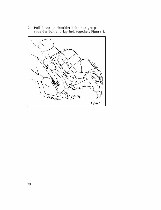
*[SR16350(BEF )04/95] 2. Pull down on shoulder belt, then graspshoulder belt and lap belt together. Figure 1.
*[SR16355(BEF )04/95]
half page art:0011238-B
File:ltsrb.exUpdate:Tue Jun 20 16:58:10 1995

41
*[SR16360(BEF )04/95] 3. While holding the shoulder and lap beltportions together, route the tongue throughthe child seat according to the child seatmanufacturer’s instructions. See Figure 2. Besure that the belt webbing is not twisted.
[SR16365(BEF )04/95]
half page art:0011239-B
Routing the lap/shoulder belt
File:ltsrb.exUpdate:Tue Jun 20 16:58:10 1995

42
*[SR16370(BEF )04/95] 4. Insert the belt tongue into the buckle for thatseating position until you hear and feel thelatch engage. Figure 3. Make sure tongue islatched securely to buckle by pulling ontongue.
*[SR16375(BEF )04/95]
half page art:0011240-B
Buckling the belt
File:ltsrb.exUpdate:Tue Jun 20 16:58:10 1995

43
*[SR16380(BEF )04/95] 5. Grasp the shoulder portion of the belt andpull downward until all of the belt isextracted and a click is heard. At this time,the retractor is in the automatic lockingmode (child seat restraint mode). Figure 4.
*[SR16385(BEF )04/95] NOTE: The dual-locking mode retractor mustbe in the automatic locking mode toproperly restrain a child.
*[SR16390(BEF )04/95]
half page art:0011241-A
Setting the retractor to automatic locking mode
File:ltsrb.exUpdate:Tue Jun 20 16:58:10 1995

44
*[SR16395(BEF )04/95] 6. Allow the belt to retract. Pull up on theshoulder webbing. A clicking sound will beheard as the belt retracts. This indicates theretractor is in the automatic locking mode.Push down on the child seat while you pullup on the belt to remove any slack in thebelt. Figures 5 and 6.
*[SR16400(BEF )04/95]
half page art:0011242-A
File:ltsrb.exUpdate:Tue Jun 20 16:58:10 1995

45
*[SR16405(BEF )04/95]
half page art:0011243-A
File:ltsrb.exUpdate:Tue Jun 20 16:58:10 1995

46
*[SR16410(BEF )04/95] 7. Before placing the child in the child seat,forcibly tilt the seat from side to side, andtug it forward to make sure that the seat issecurely held in place, Figure 7.
*[SR16412(BEF )04/95]
half page art:0011244-A
Checking that the seat is secure
File:ltsrb.exUpdate:Tue Jun 20 16:58:10 1995

47
*[SR16415(BEF )04/95] 8. Double check that the retractor is in theautomatic locking mode. Try to pull morebelt out of the retractor. If you cannot, thebelt is in the automatic locking mode,Figure 8.
*[SR16420(BEF )04/95]
half page art:0011245-B
Checking the retractor
*[SR16425(BEF )04/95] 9. Check to make sure that the child seat isproperly secured prior to each use. If theretractor is not locked, repeat steps 4through 7.
*[SR16430(BEF )04/95] To remove the retractor from automatic lockmode, allow webbing to retract fully to itsstowed position and the retractor willautomatically switch back to the vehicle sensitivelocking mode for normal adult usage.
File:ltsrb.exUpdate:Tue Jun 20 16:58:10 1995

48
[SR16440(BEF )04/95] Installing a Child Safety Seat at the RearCenter Seating Position with LockingAdjustable Lap Belt
[SR16450(BEF )04/95] 1. Lengthen the lap belt. To lengthen the belt,hold the tongue so that its bottom isperpendicular to the direction of webbingwhile sliding the tongue up the webbing.
[SR16455(BEF )04/95] 2. Place the child safety seat in the centerseating position.
[SR16460(BEF )04/95] 3. Route the tongue and webbing through thechild seat according to the child seatmanufacturer’s instructions.
[SR16465(BEF )04/95] 4. Insert the belt tongue into the proper bucklefor the center seating position until you heara snap and feel it latch. Make sure thetongue is securely fastened to the buckle bypulling on tongue.
[SR16470(BEF )04/95] 5. Push down on the child seat while pullingon the loose end of the lap belt webbing totighten the belt.
[SR16475(BEF )04/95] 6. Before placing the child into child seat,forcibly tilt the child seat from side-to-sideand in forward directions to ensure that theseat is held securely in place. If the childseat moves excessively, repeat steps 5through 6, or properly install the child seatin a different seating position.
File:ltsrb.exUpdate:Tue Jun 20 16:58:10 1995

49
[SR16480(B )04/95] Installing Child Safety Seats at the RearOutboard Seating Positions (For lap andshoulder belts combination with “cinchtongues”)
[SR16485(B )04/95] Your vehicle is equipped with rear seat safetybelts containing a “cinch tongue.” The rearoutboard safety belts will have the followinglabel:
[SR16490(B )05/95]
half page art:0021502-A
File:ltsrb.exUpdate:Tue Jun 20 16:58:10 1995
50
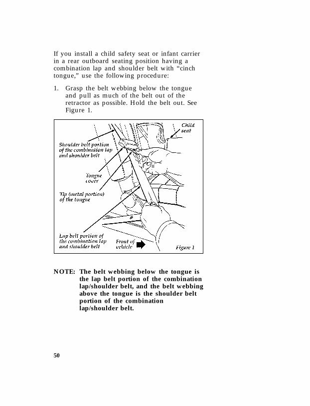
[SR16495(B )04/95] If you install a child safety seat or infant carrierin a rear outboard seating position having acombination lap and shoulder belt with “cinchtongue,” use the following procedure:
*[SR16500(B )04/95] 1. Grasp the belt webbing below the tongueand pull as much of the belt out of theretractor as possible. Hold the belt out. SeeFigure 1.
[SR16505(B )05/95]
half page art:0011363-A
*[SR16510(B )04/95] NOTE: The belt webbing below the tongue isthe lap belt portion of the combinationlap/shoulder belt, and the belt webbingabove the tongue is the shoulder beltportion of the combinationlap/shoulder belt.
File:ltsrb.exUpdate:Tue Jun 20 16:58:10 1995

51
*[SR16515(B )04/95] 2. With your other hand, grasp the tip (metalportion) of the tongue (not the cover) andslide the tongue up the webbing as far as itwill go. See Figure 1. Release the tongue, butdo not let go of the lap portion of the beltwebbing.
*[SR16520(B )04/95] 3. While still holding the belt webbing belowthe tongue in one hand, use your other handto grasp the tip (metal portion) of the tongueand belt webbing together, and again pullout as much of the belt as possible. Then, letgo of the lap portion of the belt webbing.
*[SR16525(B )04/95] 4. While holding the shoulder and lap beltportions together, route the tongue andwebbing through the child seat according tothe child seat manufacturer’s instructions.See Figure 2. Be sure that the belt webbingis not twisted.
*[SR16530(B )05/95]
half page art:0011364-A
File:ltsrb.exUpdate:Tue Jun 20 16:58:10 1995

52
*[SR16535(B )04/95] 5. Insert the belt tongue into the proper bucklefor that seating position until you hear asnap and feel it latch. Make sure the tongueis securely latched to the buckle by pullingon the tongue. See Figure 3.
*[SR16540(B )05/95]
half page art:0011365-A
File:ltsrb.exUpdate:Tue Jun 20 16:58:10 1995

53
*[SR16545(B )04/95] 6. Push down on the child seat and pull up onthe shoulder belt portion to tighten the lapbelt portion of the combination lap andshoulder belt. See Figure 4.
*[SR16550(B )05/95]
half page art:0011366-A
File:ltsrb.exUpdate:Tue Jun 20 16:58:10 1995

54
*[SR16555(B )04/95] 7. Grasp belt close to child seat and pull on theshoulder belt portion of the combinationlap/shoulder belt, then allow the belt toretract and remove all slack to securelytighten the child safety seat in the vehicle.See Figure 5.
*[SR16560(B )05/95]
half page art:0011367-A
File:ltsrb.exUpdate:Tue Jun 20 16:58:10 1995

55
*[SR16565(B )04/95] 8. Before placing the child into the child seat,forcibly tilt the child seat from side-to-sideand in forward directions to make sure thatthe seat is held securely in place. See Figures6 and 7. If the child seat moves excessively,repeat steps 6 through 8, or properly installthe child seat in a different seating position.
[SR16570(B )05/95]
half page art:0011368-A
File:ltsrb.exUpdate:Tue Jun 20 16:58:10 1995

56
*[SR16575(B )05/95]
half page art:0011369-A
*[SR16580(B )04/95] 9. Check from time to time to be sure thatthere is no slack in the lap/shoulder belt.The shoulder belt must be snug to keep thelap belt tight during a collision.
File:ltsrb.exUpdate:Tue Jun 20 16:58:10 1995
57
*[SR18400(BEF )04/95] Attaching Safety Seats With Tether Straps
*[SR18410(BEF )03/01] General Instructions
[SR18413(BEF )02/95] Some manufacturers make safety seats thatinclude an upper tether strap that goes over theseatback and attaches to an anchoring point.Other manufacturers offer the tether strap as anaccessory. Contact the manufacturer of yourchild safety seat for information about orderinga tether strap.
*[SR18417(B )12/91] You can attach a tether strap anchor bracket tothe rear floor by using a tether anchor kit(613D74), available at no charge from any Forddealership.
*[SR18420(BEF )03/91] Read and follow the instructions provided withthe kit carefully for installation of the childtether strap anchor.
*[SR18501(BEF )03/91] Follow the child seat manufacturer’s instructionsto attach the tether strap to the tether bracket.
*[SR18700(B )04/95] Ford recommends placement of tethered safetyseats in a rear seating position with the tetherstrap installed to the tether anchoring point asshown in the instructions provided with thechild tether strap anchor kit.
[SR18875(B )04/95] This vehicle has provisions to install a tetheranchorage in the front, right hand and all secondrow seating positions. It is easiest to install atether anchor at the second row, rear, centerseating position.
[SR18900(B )03/91] If the tethered seat is installed in the front seat,Ford recommends the center front seatingposition, with the tether strap secured to thecenter rear lap belt tongue or to the webbing ofthe buckled center rear lap belt behind the childsafety seat. The front, right hand seating positionmay be used if it is the only seating positionavailable.
File:ltsrb.exUpdate:Tue Jun 20 16:58:10 1995

58
*[SR18950(BEF )05/95] RWARNING
Only use the tether attachment holelocations shown in the illustrations. Thetether anchor may not perform properly ifthe wrong mounting location is used.
*[SR19400(B F )04/95] The rear lap/shoulder safety belts should not beused to secure the tether strap of a safety seatlocated in the front seat.
*[SR19500(BEF )05/95] RWARNING
Failure to follow these precautions couldincrease the chance of injury in anaccident.
*[SR19550(B )05/95] RWARNING
If the anchor bolt(s) is ever removed, thehole(s) in the floor must be sealed toprevent the possibility of exhaust fumesentering the passenger compartment.
File:ltsrb.exUpdate:Tue Jun 20 16:58:10 1995

59
Starting Your Bronco
*[ST01700( ALL)03/95] Ignition%*[ST01800( ALL)01/95] Understanding the Positions of the Ignition
*[ST02000( ALL)05/90]
quarter page art:0020004-B
The positions of the key in the ignition lock cylinder.
*[ST02200( ALL)03/95] ON allows you to test your vehicle’s warninglights (except the brake system warning light) tomake sure they work before you start theengine. The key returns to the ON position oncethe engine is started and remains in this positionwhile the engine runs.
*[ST02300( ALL)03/95] START cranks the engine. Release the key oncethe engine starts so that you do not damage thestarter. The key should return to ON when yourelease it. The START position also allows youto test the brake warning light.
*[ST02400( ALL)03/95] OFF allows you to shut off the engine and allaccessories without locking the steering wheel orthe automatic transmission gearshift lever.
[ST02500(B F )05/95] LOCK locks the steering wheel. It also locks thegearshift if your vehicle’s gearshift is on thecolumn.
File:ltstb.exUpdate:Fri Jun 9 15:30:44 1995

60
*[ST02600(B F )05/95] RWARNING
LOCK position does not lock the gearshifton floor-mounted gearshifts. If theparking brake is not set and the gearshiftis moved out of Park (automatictransmission) or out of gear (manualtransmission), your vehicle may moveunexpectedly.
[ST02635(B F )05/95] With the transfer case in N (Neutral), the vehicleis free to move with either the automatictransmission in P (Park) or with the manualtransmission in any driving gear.
*[ST02650(B F )05/95] RWARNING
Do not leave the vehicle unattended withthe transfer case in the N (Neutral)position. Always set the parking brakefully and turn off the ignition whenleaving the vehicle.
*[ST02700( ALL)01/95] LOCK is the only position that allows you toremove the key. The LOCK feature helps toprotect your vehicle from theft.
%*[ST02800( ALL)05/95] If the key is stuck in the LOCK position, movethe steering wheel left or right until the keyturns freely.
%*[ST02900( ALL)03/95] ACCESSORY allows some of your vehicle’selectrical accessories such as the radio and thewindshield wipers to operate while the engine isnot running.
*[ST02950(B F )01/95] In order to turn the key from the ON or OFFposition to the ACCESSORY position, you mustpush the key release button if your vehicle’smanual transmission gearshift is mounted on thefloor.
File:ltstb.exUpdate:Fri Jun 9 15:30:44 1995

61
*[ST03025(BEF )03/91] Ignition Key Buzzer or Chime
*[ST03050(BEF )03/91] The buzzer or chime will sound if you open thedriver’s door while the key is in the ignition.Never leave your vehicle unattended with thekey in the ignition.
%*[ST03075( ALL)02/95] Removing the Key From the Ignition
*[ST03100(B F )03/91] Procedures for removing your key from theignition will vary, depending on the type ofgearshift your vehicle has. Gearshift levers maybe mounted on the steering column or on thefloor or console.
*[ST03115(B F )05/91] If you have a manual transmission, you have akey release lever which allows you to removeyour key from the ignition. The key release leveris on the upper right of the steering column, justabove the key lock cylinder. The lever saysPUSH.
*[ST03120(B F )05/91]
quarter page art:0020833-A
Key release lever
*[ST03300(B F )03/91] If your vehicle’s gearshift lever is mountedon the column:
*[ST03400( ALL)03/95] 1. Put the gearshift in Park.
*[ST03500( ALL)03/91] 2. Set the parking brake fully before removingyour foot from the service brake. (This willavoid “binding” or “loading” the park gearif you park on a grade.)
*[ST03600( ALL)03/95] 3. Turn the ignition key to LOCK.
File:ltstb.exUpdate:Fri Jun 9 15:30:44 1995

62
*[ST03700( ALL)03/95] 4. Remove the key.
*[ST03800(B F )03/91] If your vehicle’s gearshift lever is mountedon the floor:
*[ST03950(B F )03/95] 1. Put the gearshift in 1 (First).
*[ST04000(B F )03/91] 2. Turn the ignition key to OFF.
*[ST04100(B F )05/91] 3. Set the parking brake fully before removingyour foot from the service brake.
*[ST04200(B F )06/92] 4. Push and hold in the key release button.
*[ST04300(B F )10/90] 5. Turn the key to LOCK.
*[ST04400(B F )03/95] 6. Remove the key.
*[ST04600(B F )05/95] RWARNING
Always set the parking brake fully andmake sure that the gearshift is latched inP (Park) (automatic transmission) or 1(First) (manual transmission).
[ST04635(B F )05/95] With the transfer case in N (Neutral), the vehicleis free to move with either the automatictransmission in P (Park) or with the manualtransmission in any driving gear.
*[ST04650(B F )05/95] RWARNING
Do not leave the vehicle unattended withthe transfer case in the N (Neutral)position. Always set the parking brakefully and turn off the ignition whenleaving the vehicle.
File:ltstb.exUpdate:Fri Jun 9 15:30:44 1995
63
*[ST04750( ALL)01/93] RWARNING
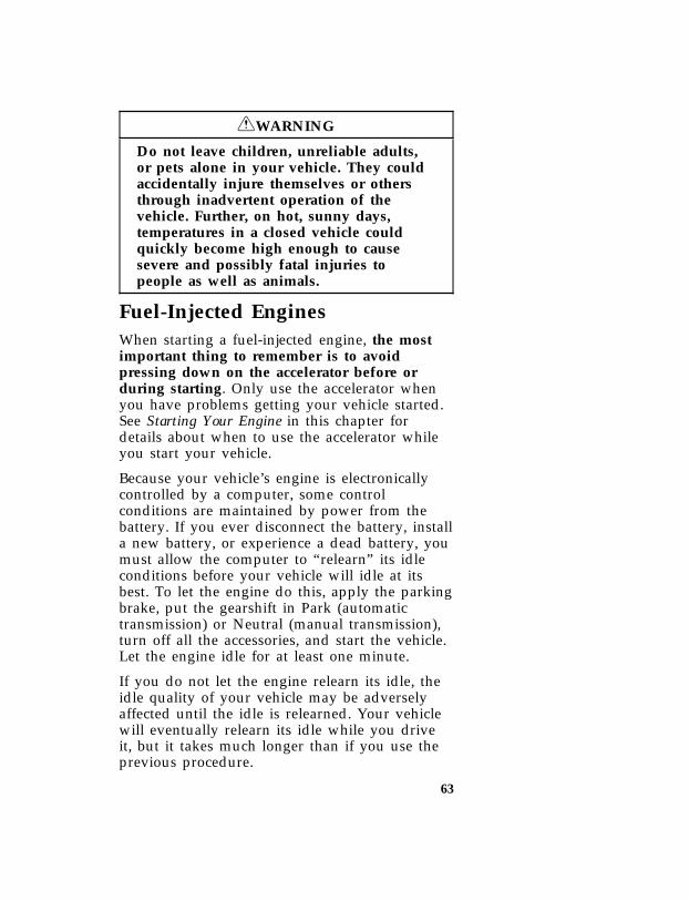
Do not leave children, unreliable adults,or pets alone in your vehicle. They couldaccidentally injure themselves or othersthrough inadvertent operation of thevehicle. Further, on hot, sunny days,temperatures in a closed vehicle couldquickly become high enough to causesevere and possibly fatal injuries topeople as well as animals.
%*[ST04800( ALL)03/95] Fuel-Injected Engines
*[ST04900(BEF )03/95] When starting a fuel-injected engine, the mostimportant thing to remember is to avoidpressing down on the accelerator before orduring starting. Only use the accelerator whenyou have problems getting your vehicle started.See Starting Your Engine in this chapter fordetails about when to use the accelerator whileyou start your vehicle.
*[ST05000(B F )01/95] Because your vehicle’s engine is electronicallycontrolled by a computer, some controlconditions are maintained by power from thebattery. If you ever disconnect the battery, installa new battery, or experience a dead battery, youmust allow the computer to “relearn” its idleconditions before your vehicle will idle at itsbest. To let the engine do this, apply the parkingbrake, put the gearshift in Park (automatictransmission) or Neutral (manual transmission),turn off all the accessories, and start the vehicle.Let the engine idle for at least one minute.
*[ST05100(BEF )03/95] If you do not let the engine relearn its idle, theidle quality of your vehicle may be adverselyaffected until the idle is relearned. Your vehiclewill eventually relearn its idle while you driveit, but it takes much longer than if you use theprevious procedure.
File:ltstb.exUpdate:Fri Jun 9 15:30:44 1995

64
[ST05150( ALL)02/95] Starting your vehicle%*[ST05200( ALL)05/94] Preparing to Start Your Vehicle
*[ST05300( ALL)05/95] RWARNING
Do not start your vehicle in a closedgarage or other enclosed area. Never sit ina stopped vehicle for more than a shortperiod of time with the engine running.Exhaust fumes are toxic. See GuardingAgainst Exhaust Fumes in this chapter formore instructions.
*[ST05400( ALL)01/95] Before you start your vehicle, do the following:
*[ST05500(BEF )01/95] 1. Make sure you and all your passengersbuckle your safety belts. See Safety Restraintsin the Index for more details.
*[ST05600( ALL)03/95] 2. Make sure the headlamps and otheraccessories are turned off when starting.
*[ST05700(B F )10/94] 3. If you have an automatic transmission,make sure that the gearshift lever is in P(Park) and the parking brake is set beforeyou turn the key.
*[ST05800(B F )03/91] 4. If you have a manual transmission, makesure that the parking brake is fully set, pushthe clutch pedal to the floor, and put thegearshift into Neutral before you turn thekey. (Remember, the starter will operate onlyif the clutch pedal is pushed in all the way).
*[ST05900(BEF )03/95] Testing the Warning Lights
*[ST06015(BEF )03/95] Before you start your vehicle, you should testthe warning lights on the instrument panel tomake sure that they work. Refer to the WarningLights and Gauges chapter.
*[ST06025(BEF )03/95] If your Brake Warning Light does light up withthe key in the ON position, you may not have
File:ltstb.exUpdate:Fri Jun 9 15:30:44 1995

65
fully released the parking brake or the brakefluid may be low.
%*[ST06200( ALL)02/95] Starting Your Engine
*[ST06300( ALL)02/95] To start your engine:
*[ST06400( ALL)05/95] 1. Follow the steps under Preparing to StartYour Vehicle at the beginning of this section.
*[ST06425( ALL)03/95] 2. Turn the ignition key to the ON position.
*[ST06451(BEF )03/95] 3. DO NOT depress the accelerator pedal whenstarting your engine. DO NOT use theaccelerator while the vehicle is parked.
*[ST06475( ALL)02/95] 4. Turn the key to the START position(cranking) until the engine starts. Allow thekey to return to the ON position after theengine has started.
*[ST06501( ALL)02/95] If you have difficulty in turning the key,rotate the steering wheel slightly because itmay be binding.
%*[ST06510( ALL)04/95] For a cold engine:
*[ST06515( ALL)04/95] ❑At temperatures 10˚F (-12˚C) and below: Ifthe engine does not start in fifteen (15)seconds on the first try, turn the key to OFF,wait approximately ten (10) seconds so youdo not flood the engine, then try again.
*[ST06520( ALL)04/95] ❑At temperatures above 10˚F (-12˚C): If theengine does not start in five (5) seconds onthe first try, turn the key to OFF, waitapproximately ten (10) seconds so you do notflood the engine, then try again.
*[ST06525( ALL)03/95] ❑Do not hold the key in the START positionfor more than fifteen (15) seconds at a time.
File:ltstb.exUpdate:Fri Jun 9 15:30:44 1995
66
%*[ST06550( ALL)04/95] For a warm engine:
*[ST06551( ALL)04/95] ❑Do not hold the key in the START positionfor more than five (5) seconds at a time. Ifthe engine does not start within five (5)seconds on the first try, turn the key to theOFF position. Wait a few seconds after thestarter stops, then try again.
*[ST06575( ALL)04/95] Whenever you start your vehicle, release the keyas soon as the engine starts. Excessive crankingcould damage the starter or flood the engine.
*[ST06601( ALL)04/95] After you start the engine, let it idle for a fewseconds. Keep your foot on the brake pedal andput the gearshift lever in gear. Release theparking brake. Slowly release the brake pedaland drive away in the normal manner.
*[ST06625( ALL)01/95] NOTE: Your vehicle is equipped with abrake-shift interlock feature. Thisfeature prevents you from shiftingfrom P (Park) unless you have thebrake pedal depressed. (The ignitionmust be in the ON position.) If youcannot shift from P (Park) with thebrake pedal depressed:
*[ST06627( ALL)01/95] 1. Apply the parking brake.
*[ST06629( ALL)01/95] 2. Remove the key.
*[ST06631( ALL)01/95] 3. Insert the key and rotate one positionclockwise (ignition in the OFF position).
*[ST06633( ALL)01/95] 4. Apply the brake pedal and shift to N(Neutral). (If the vehicle is shifted to P(Park), you must repeat the previous steps.)
*[ST06635( ALL)01/95] 5. Start the vehicle.
*[ST06637( ALL)05/95] If you need to shift out of P (Park) by using thealternate procedure described above, it ispossible that a fuse has blown and that yourbrakelamps may also not be functional. Please
File:ltstb.exUpdate:Fri Jun 9 15:30:44 1995

67
refer to the chapter titled Servicing Your Broncoin this Owner Guide for instructions on checkingand replacing fuses.
*[ST06640( ALL)05/95] RWARNING
DO NOT DRIVE YOUR VEHICLE UNTILYOU VERIFY THAT THE BRAKELAMPSARE WORKING.
*[ST06775( ALL)03/95] For cold or warm engines:
*[ST06800( ALL)03/95] If the engine still does not start after twoattempts:
*[ST06825( ALL)04/95] 1. Turn the ignition key to the OFF position.
*[ST06851( ALL)04/95] 2. Press the accelerator all the way to the floorand hold it.
*[ST06876( ALL)04/95] 3. Turn the ignition key to the START position.
*[ST06900( ALL)04/95] 4. Release the ignition key when the enginestarts.
*[ST06925( ALL)04/95] 5. Release the accelerator gradually as theengine speeds up. Then drive away in thenormal manner.
*[ST06951( ALL)04/95] If the engine still does not start, the fuel pumpshut-off switch may have been triggered. Fordirections on how to reset the switch see FuelPump Shut-Off Switch later in this chapter.
*[ST07300(BEF )05/95] A computer system controls the engine’s idlespeed. When you start your vehicle, the engine’sidle speed normally runs higher than when it’swarmed up. These faster engine speeds willmake your vehicle move slightly faster than itsnormal idle speed. It should, however, slowdown after a short time. If it does not, have theidle speed checked.
File:ltstb.exUpdate:Fri Jun 9 15:30:44 1995

68
*[ST07350( ALL)05/95] If the engine idle speed does not slow downautomatically, do not allow your vehicle to idlefor more than 10 minutes. Have the vehiclechecked.
*[ST07400( ALL)05/95] RWARNING
Extended idling at high engine speeds canproduce very high temperatures in theengine and exhaust system, creating therisk of fire or other damage.
*[ST07450( ALL)05/95] RWARNING
Do not park, idle, or drive your vehicle indry grass or other dry ground cover. Theemission system heats up the enginecompartment and exhaust system, whichcan start a fire.
*[ST07500(BEF )03/95] If you consistently start your vehicle in subzerotemperatures, use an engine block heater (ifyour vehicle has this option).
%*[ST07600(BEF )03/95] Engine Block Heater (If equipped)(Standard in Canada)
*[ST07700(BEF )03/95] Engine block heaters are strongly recommendedif you live in a region where temperatures reach-10˚F (-23˚C) or below. An engine block heaterwarms the engine coolant, which improvesstarting, warms up the engine faster, and allowsthe heater-defrost system to respond quickly.
*[ST08000(BEF )05/95] RWARNING
To prevent electrical shock, do not useyour heater with ungrounded electricalsystems or two-pronged (cheater) adapters.
File:ltstb.exUpdate:Fri Jun 9 15:30:44 1995

69
*[ST08100(BEF )03/95] For best results, plug the heater in at least threehours before you start your vehicle. Using theheater for longer than three hours will notdamage the engine, so you can plug it in atnight to start your vehicle the followingmorning.
*[ST08150(BEF )12/91] NOTE: Be sure to disconnect the engine blockheater before driving your vehicle.
%*[ST08160( ALL)03/95] If the Engine Cranks but DoesNot Start or Does Not Start Aftera Collision
*[ST08170(BEF )04/95] Fuel Pump Shut-off Switch
*[ST08190( ALL)03/95] If the engine cranks but does not start or doesnot start after a collision, the fuel pump shut-offswitch may have been triggered. The shut-offswitch is a device intended to stop the fuelpump when your vehicle has been involved in asubstantial jolt.
*[ST08200( ALL)03/95] Once the shut-off switch is triggered, you mustreset the switch by hand before you can startyour vehicle.
*[ST08210(B F )03/95]
one third page art:0020005-C
Fuel pump shut-off switch location
File:ltstb.exUpdate:Fri Jun 9 15:30:44 1995
70
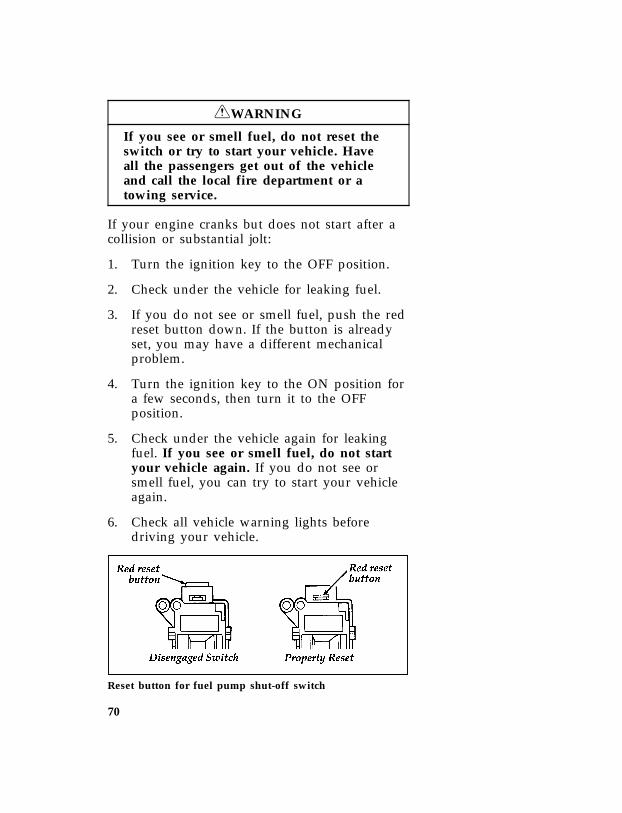
*[ST08260( ALL)05/95] RWARNING
If you see or smell fuel, do not reset theswitch or try to start your vehicle. Haveall the passengers get out of the vehicleand call the local fire department or atowing service.
*[ST08270( ALL)03/95] If your engine cranks but does not start after acollision or substantial jolt:
*[ST08280( ALL)04/95] 1. Turn the ignition key to the OFF position.
*[ST08290( ALL)03/95] 2. Check under the vehicle for leaking fuel.
*[ST08300( ALL)03/95] 3. If you do not see or smell fuel, push the redreset button down. If the button is alreadyset, you may have a different mechanicalproblem.
*[ST08310(BEF )03/95] 4. Turn the ignition key to the ON position fora few seconds, then turn it to the OFFposition.
*[ST08330( ALL)03/95] 5. Check under the vehicle again for leakingfuel. If you see or smell fuel, do not startyour vehicle again. If you do not see orsmell fuel, you can try to start your vehicleagain.
*[ST08340( ALL)03/95] 6. Check all vehicle warning lights beforedriving your vehicle.
*[ST08350(BEF )03/95]
quarter page art:0020107-A
Reset button for fuel pump shut-off switch
File:ltstb.exUpdate:Fri Jun 9 15:30:44 1995

71
%*[ST09300( ALL)02/95] Guarding Against Exhaust Fumes
*[ST09400( ALL)02/95] Carbon monoxide, although colorless andodorless, is present in exhaust fumes. Takeprecautions to avoid its dangerous effects.
*[ST09500( ALL)05/95] RWARNING
Do not start your vehicle in a closedgarage or other enclosed area. Never sit ina stopped vehicle for more than a shortperiod of time with the engine running.Exhaust fumes are toxic. See GuardingAgainst Exhaust Fumes in this chapter formore instructions.
*[ST09600( ALL)05/95] RWARNING
If you smell exhaust fumes inside yourvehicle, have your dealer inspect yourvehicle immediately. Do not drive if yousmell exhaust fumes.
[ST09800(B )06/92] Make sure your Bronco’s tailgate window isclosed when your truck is running to preventexhaust fumes from being drawn in. If you musthave the tailgate window open, adjust your aircontrol system to force outside air into the frontof your truck. If your Bronco has outside aircontrol vents, open them fully.
*[ST09900( ALL)01/95] Have the exhaust and body ventilation systemschecked whenever:
*[ST10000( ALL)02/95] ❑your vehicle is raised for service
*[ST10100( ALL)02/95] ❑ the sound of the exhaust system changes
*[ST10200( ALL)01/95] ❑your vehicle has been damaged in a collision
*[ST10300( ALL)01/95] Improve your ventilation by keeping all air inletvents clear of snow, leaves, and other debris.
File:ltstb.exUpdate:Fri Jun 9 15:30:44 1995

72
*[ST10400( ALL)03/95] If the engine is idling while you are stopped inan open area for long periods of time, open thewindows at least one inch (2.5 cm). Also, adjustthe heating or air conditioning to bring inoutside air.
*[ST10600(B F )03/91] ❑HEATING — Set fan speed at MEDIUM orHIGH, the function selector knob on VENT,FLOOR, MIX, or the DEFROST symbol andthe temperature control knob on any desiredposition.
*[ST10800(B F )03/91] ❑AIR CONDITIONING — Set the fan speed atMEDIUM or HIGH, the function selectorknob on NORM or VENT and thetemperature control knob on any desiredposition.
File:ltstb.exUpdate:Fri Jun 9 15:30:44 1995

73
Warning Lights andGauges
*[LG00400( ALL)01/95] The instrument panel (dashboard) on yourvehicle is divided into several different sections.The illustrations on the following pages showthe major parts of the instrument panel that aredescribed in this chapter. Some items shownmay not be on all vehicles.
*[LG00500(B F )02/95] Your vehicle has one of the following clusters:
*[LG00600(B F )11/89] ❑A mechanical cluster
*[LG00700(B F )11/89] ❑A mechanical cluster with tachometer
*[LG00900(B F )12/89] If you are not sure which cluster your vehiclehas, check the diagrams on the following pagesof this section.
File:ltlgb.exUpdate:Fri Jun 9 15:30:26 1995

74
*[LG02200(BF)05/95]
fullpageart:0020036-K
Mech
anical
cluster
File:ltlgb.exU
pdate:Fri Jun 9 15:30:26 1995

75
*[LG02400(BF)05/95]
fullpageart:0020038-N
Mech
anical
cluster
with
tachom
eter
File:ltlgb.exU
pdate:Fri Jun 9 15:30:26 1995

76
*[LG03000( ALL)06/94] The Mechanical Cluster
*[LG03100( ALL)06/93] The following warning lights and gauges are onthe mechanical cluster. All of the warning lightsand gauges alert you to possible problems withyour vehicle. Some of the lights listed areoptional. The following sections detail what eachof these indicators means.
*[LG03200( ALL)03/95] Brake System Warning Light
*[LG03300(B M)03/95] The warning light for the brakes can show twothings — that the parking brake is not fullyreleased, or that the brake fluid level is low inthe master cylinder reservoir. If the fluid level islow, the brake system should be checked byyour dealer or a qualified service technician.
*[LG03400( ALL)05/94] This light comes on when you turn the ignitionkey to START to verify that the indicator bulb isworking. If the light stays on or comes on afteryou have released the parking brake fully, havethe hydraulic brake system serviced.
*[LG03500( ALL)05/95] RWARNING
The BRAKE light indicates that the brakesmay not be working properly. Have thebrakes checked immediately.
*[LG03600( ALL)11/89]
one inch art:0020044-A
Brake warning light symbols
File:ltlgb.exUpdate:Fri Jun 9 15:30:26 1995

77
*[LG03800(BEF )02/95] Anti-Lock Brake System Warning Light
*[LG03925(BEF )03/03] To check the amber ABS brake warning lightturn the ignition key to ON. The ABS brakewarning light should glow momentarily.
*[LG03950(BEF )06/94] NOTE: If it does not glow momentarily, haveyour vehicle’s electrical system checkedimmediately.
*[LG03985(BEF )07/94] NOTE: If the ABS brake warning light beginsto flash in a repeatable flash sequence,check the rear anti-lock systemcontinuous power fuse and brake lightsfor proper operation.
[LG04050(BEF )05/95]
one inch art:0020913-B
Anti-lock warning light symbol
*[LG04100(BEF )05/95] RWARNING
If the anti-lock brake system warninglight remains on or comes on whiledriving, have the braking system checkedby a qualified service technician as soonas possible.
*[LG04125(BEF )05/95] NOTE: If a fault occurs in the anti-locksystem, and the brake warning light isnot lit, the anti-lock system is disabledbut normal brake function remainsoperational.
File:ltlgb.exUpdate:Fri Jun 9 15:30:26 1995

78
*[LG04150(BEF )02/95] Safety Belt Warning Light and Chime
*[LG04301(BEF )03/95] This warning light and chime remind you tofasten your safety belt. The following conditionswill take place:
*[LG04325(BEF )03/95] ❑ If the safety belt is not buckled when the keyis turned to the ON position, the light comeson for 1 to 2 minutes and the chime soundsfor 4 to 8 seconds.
*[LG04351(BEF )02/95] ❑ If the safety belt is buckled while the light ison and the chime is sounding, both the lightand chime turn off.
*[LG04365(BEF )05/95] ❑ If the safety belt is buckled before theignition is turned to the ON position, neitherthe light nor the chime will come on.
*[LG04400( ALL)10/92]
one inch art:0020046-B
Safety belt warning light symbol
*[LG04500( ALL)03/95] Check Engine Warning Light
*[LG04525( ALL)05/95] The Powertrain On-Board Diagnostic II (OBD II)system consists of the hardware and softwarenecessary to monitor the operation of thepowertrain. The OBD II system is designed tocheck the function of the vehicle’s powertraincontrol system during normal operation. If anemission problem is detected, the Check EngineWarning Light (in the cluster) is turned on.
File:ltlgb.exUpdate:Fri Jun 9 15:30:26 1995

79
*[LG04550( ALL)05/95]
one inch art:0020048-A
Check engine warning light symbol
*[LG04575( ALL)05/95] Modification or additions to the vehicle maycause incorrect operation of the OBD II system.Additions such as burglar alarms, cellularphones, and CB radios must be carefullyinstalled. Do not install these devices by tappinginto or running wires close to powertrain controlsystem wires or components.
*[LG04600( ALL)05/95] The light comes on briefly when you turn theignition key to ON, but it should turn off whenthe engine starts. If the light does not come onwhen you turn the ignition to ON or if it comeson and stays on when you are driving, haveyour vehicle serviced as soon as possible. Thisindicates a possible problem with one of thevehicle’s emission control systems. You do notneed to have your vehicle towed in.
*[LG04625( ALL)05/95] If the light turns on and off at one (1) secondintervals while you are driving the vehicle, itmeans that the engine is misfiring. If thiscondition persists, damage could occur to theengine or catalytic convertor. Have your vehicleserviced at the first opportunity. You do notneed to have your vehicle towed in.
*[LG04650( ALL)05/95] If the light turns on and off on rare occasionswhile you are driving, it means that amalfunction occurred and the condition correcteditself.
File:ltlgb.exUpdate:Fri Jun 9 15:30:26 1995

80
*[LG04675( ALL)05/95] An example of a condition which corrects itselfoccurs when an engine running out of fuelbegins to misfire. In this case, the Check EngineWarning Light may turn on and will then set aDiagnostic Trouble Code indicating that theengine was misfiring while the last of the fuelwas being consumed. After refueling, the CheckEngine Warning Light will turn off after thevehicle has completed three consecutive warmup cycles without a misfire condition occurring.A warm up cycle consists of engine start from acold condition (engine at ambient temperature)and running until the engine reaches normaloperating temperature.
*[LG04700( ALL)05/95] On the fourth engine start up, the Check EngineWarning Light will turn off as soon as theengine begins to crank. It is not necessary tohave the engine serviced.
*[LG04725( ALL)05/95] Under certain conditions, the Check EngineWarning Light may come on if the fuel cap isnot properly installed. If the Check EngineWarning Light comes on and you suspect thatthe fuel cap is not properly installed, pull off theroad as soon as it is safely possible and turn offthe engine. Remove and replace the fuel cap,making sure it is properly seated.
*[LG04750( ALL)05/95] After completing the three consecutive warm upcycles and on the fourth engine start up, theCheck Engine Warning Light should turn off. Ifthe light does not go off after the fourth enginerestart, have your vehicle serviced by yourdealer or a qualified technician.
File:ltlgb.exUpdate:Fri Jun 9 15:30:26 1995
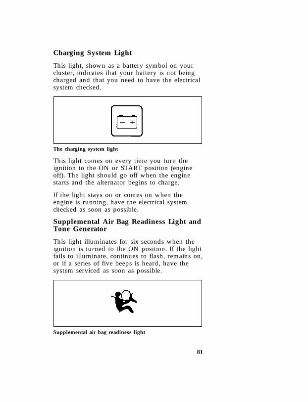
81
*[LG05900( ALL)01/95] Charging System Light
*[LG06000( ALL)03/95] This light, shown as a battery symbol on yourcluster, indicates that your battery is not beingcharged and that you need to have the electricalsystem checked.
*[LG06050( ALL)03/91]
one inch art:0020777-A
The charging system light
*[LG06100( ALL)05/95] This light comes on every time you turn theignition to the ON or START position (engineoff). The light should go off when the enginestarts and the alternator begins to charge.
*[LG06300(B FM)01/95] If the light stays on or comes on when theengine is running, have the electrical systemchecked as soon as possible.
*[LG06305(BEF )06/93] Supplemental Air Bag Readiness Light andTone Generator
*[LG06310(BEF )06/93] This light illuminates for six seconds when theignition is turned to the ON position. If the lightfails to illuminate, continues to flash, remains on,or if a series of five beeps is heard, have thesystem serviced as soon as possible.
[LG06320(B F )05/95]
one inch art:0000653-C
Supplemental air bag readiness light
File:ltlgb.exUpdate:Fri Jun 9 15:30:26 1995

82
*[LG06400( ALL)05/94] Battery Voltage Gauge (Voltmeter)
*[LG06601( ALL)05/94] This gauge shows you the battery voltage whenthe ignition key is in the ON position.
*[LG06700( ALL)11/89] If you are running electrical accessories (whenthe engine is off, or idling at a low speed), thepointer may move toward the lower end of thenormal band. If it stays outside the normal bandarea, have your vehicle’s electrical systemchecked as soon as it is safely possible.
*[LG06701( ALL)05/95] If the battery is operating under cold weatherconditions, the pointer may indicate in the upperrange of the NORMAL band while the battery ischarging. If you are running electrical accessorieswith the engine off or idling at a low speed, orthe battery is not fully charged, the pointer maymove toward the lower end of the NORMALband.
*[LG06750( ALL)05/94] If it stays outside the NORMAL band, have yourvehicle’s electrical system checked as soon as itis safely possible.
*[LG06900(B F )03/93]
quarter page art:0020052-D
Battery voltage gauge
File:ltlgb.exUpdate:Fri Jun 9 15:30:26 1995

83
*[LG07500( ALL)05/94] Engine Oil Pressure Gauge
*[LG07601( ALL)06/93] This gauge indicates the engine’s oil pressure,not the oil level. However, if your engine’s oillevel is low, it could affect the oil pressure. Withthe engine running, the pointer should moveinto the NORMAL band. If the pointer dropsbelow the NORMAL band while the engine isrunning, you have lost oil pressure andcontinued operation will cause severe enginedamage.
*[LG07701( ALL)03/95] If you lose engine oil pressure:
*[LG07801( ALL)01/95] 1. Pull off the road as soon as safely possible.
*[LG07901( ALL)04/95] 2. Shut off the engine immediately or severeengine damage could result.
*[LG08001( ALL)02/95] 3. Check the engine’s oil level, following theinstructions on checking and adding engineoil. Refer to Engine oil in the Index. If youdo not follow these instructions, you orothers could be injured. To assure anaccurate reading, your vehicle should be onlevel ground.
*[LG08051( ALL)03/93] 4. If the level is low, add only as much oil asnecessary before you start the engine again.Do not overfill. Do not operate the engine ifthe pointer is below the NORMAL band,regardless of the oil level. Contact yournearest dealer for further service actions.
*[LG08200(B F )03/93]
quarter page art:0020057-D
Engine oil pressure gauge
File:ltlgb.exUpdate:Fri Jun 9 15:30:26 1995

84
*[LG08900( ALL)01/95] High Beam Light
*[LG09001( ALL)03/95] This light comes on when the headlamps areturned on high beam or when you flash thelights.
*[LG09025( ALL)11/89]
one inch art:0020537-B
High beam indicator light
*[LG09300(BEF )03/95] “Headlamps On” Alert Chime
*[LG09400(BEF )03/95] This chime will sound if you open the doorwhile the headlamps or parklamps are on.
*[LG09500( ALL)01/95] Fuel Gauge
*[LG09700( ALL)06/93] The fuel gauge displays approximately howmuch fuel is in the fuel tank only when theignition switch is ON.
*[LG09860( ALL)06/93] The fuel gauge indicator may vary slightly whenthe vehicle is in motion.
*[LG09875( ALL)08/93] With ignition switch OFF, the fuel gaugeindicator may drift from the ignition switch ONposition.
*[LG10125(B F )06/93]
quarter page art:0020691-C
Fuel gauge
File:ltlgb.exUpdate:Fri Jun 9 15:30:26 1995

85
*[LG11100( ALL)01/95] Engine Coolant Temperature Gauge
*[LG11201( ALL)03/95] This gauge tells you the temperature of theengine coolant, not the coolant level. If thecoolant is not at its proper level or mixture, thegauge indicator will not be accurate.
*[LG11301( ALL)02/95] The pointer moves from the C (cold) mark intothe Normal band as the engine coolant warmsup. It is acceptable for the pointer to fluctuatewithin the Normal band under normal drivingconditions. Under certain driving conditions,such as heavy stop and go traffic or driving uphills in hot weather, the pointer may indicate atthe top of the Normal band.
*[LG11401( ALL)05/95] If, under any circumstances, the pointer movesabove the NORMAL band, the engine coolant isoverheating and continued operation may causeengine damage.
*[LG11501( ALL)01/95] If your engine coolant overheats:
*[LG11601( ALL)03/95] 1. Pull off the road as soon as it is safelypossible.
*[LG11701( ALL)03/95] 2. Turn off the engine. If you do not stop theengine as soon as safely possible, severeengine damage could result.
*[LG11801( ALL)05/95] 3. Let the engine cool. DO NOT REMOVECOOLANT SYSTEM FILL CAP UNTILTHE ENGINE IS COOL.
*[LG11901( ALL)04/95] 4. Check the coolant level following theinstructions on checking and adding coolantto your engine, see Engine Coolant in theIndex. If you do not follow theseinstructions, you or others could be injured.
*[LG12200( ALL)03/95] For instructions on checking and adding coolantto your engine, see Engine coolant in the Index. Ifyou do not follow these instructions, you orothers could be injured.
File:ltlgb.exUpdate:Fri Jun 9 15:30:26 1995
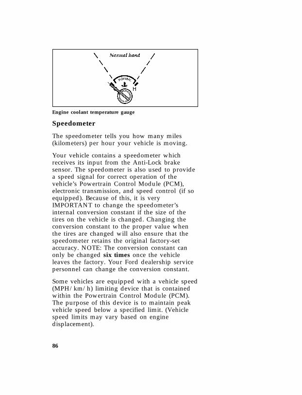
86
*[LG12350(B F )03/93]
quarter page art:0020535-D
Engine coolant temperature gauge
*[LG12601( ALL)01/95] Speedometer
*[LG12700( ALL)01/95] The speedometer tells you how many miles(kilometers) per hour your vehicle is moving.
*[LG12750(BEF )04/95] Your vehicle contains a speedometer whichreceives its input from the Anti-Lock brakesensor. The speedometer is also used to providea speed signal for correct operation of thevehicle’s Powertrain Control Module (PCM),electronic transmission, and speed control (if soequipped). Because of this, it is veryIMPORTANT to change the speedometer’sinternal conversion constant if the size of thetires on the vehicle is changed. Changing theconversion constant to the proper value whenthe tires are changed will also ensure that thespeedometer retains the original factory-setaccuracy. NOTE: The conversion constant canonly be changed six times once the vehicleleaves the factory. Your Ford dealership servicepersonnel can change the conversion constant.
*[LG12753(BEF )01/95] Some vehicles are equipped with a vehicle speed(MPH/km/h) limiting device that is containedwithin the Powertrain Control Module (PCM).The purpose of this device is to maintain peakvehicle speed below a specified limit. (Vehiclespeed limits may vary based on enginedisplacement).
File:ltlgb.exUpdate:Fri Jun 9 15:30:26 1995
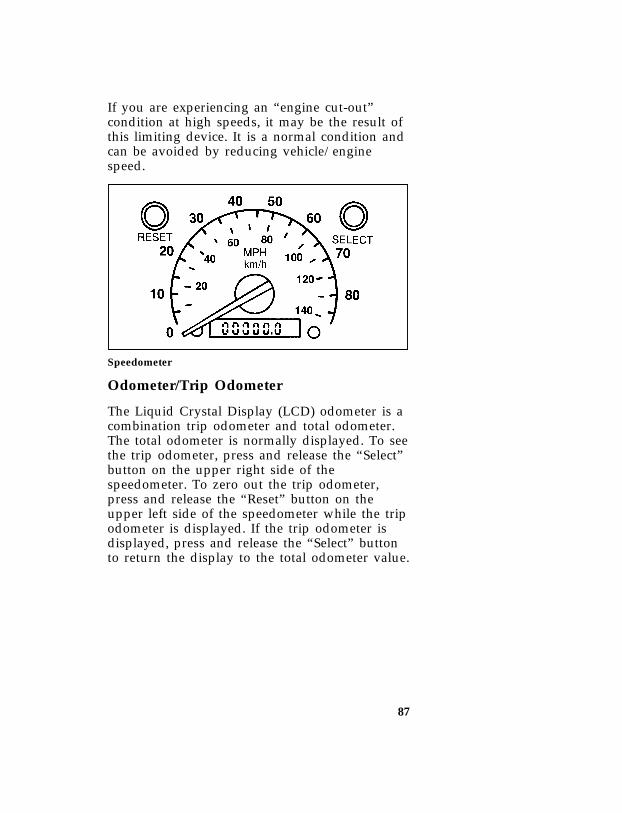
87
*[LG12756(B F )05/95] If you are experiencing an “engine cut-out”condition at high speeds, it may be the result ofthis limiting device. It is a normal condition andcan be avoided by reducing vehicle/enginespeed.
*[LG12770(B F )03/93]
one third page art:0020871-C
Speedometer
*[LG13130( ALL)10/92] Odometer/Trip Odometer
*[LG13160( ALL)10/92] The Liquid Crystal Display (LCD) odometer is acombination trip odometer and total odometer.The total odometer is normally displayed. To seethe trip odometer, press and release the “Select”button on the upper right side of thespeedometer. To zero out the trip odometer,press and release the “Reset” button on theupper left side of the speedometer while the tripodometer is displayed. If the trip odometer isdisplayed, press and release the “Select” buttonto return the display to the total odometer value.
File:ltlgb.exUpdate:Fri Jun 9 15:30:26 1995

88
*[LG13200(B F )05/95] Tachometer (If equipped)
*[LG13300(B F )05/95] The tachometer will show you the engine’sspeed measured in revolutions per minute(RPM).
*[LG13400(B F )05/95] The tachometer may move slightly when the keyis placed in the ACC or ON position, with theengine off. This is normal and does not affectthe performance of the tachometer when theengine is running.
*[LG13525(B F )05/95] Some vehicles are equipped with an enginespeed (RPM) limiting device contained withinthe Powertrain Control Module (PCM). Thepurpose of this device is to maintain peakengine speed (RPM) below a specified limit. Thisfeature is only evident on automatic transmissionvehicles when shifting manually (1, 2, D) and onall manual transmission units. (Engine speedlimits may vary based on engine displacement).
*[LG13550(B F )05/95] If you are experiencing an “engine cut-out”condition at high speeds, it may be the result ofthis limiting device. It is a normal condition andcan be avoided by reducing vehicle/enginespeed.
*[LG13665(B F )05/95]
one third page art:0020869-C
Tachometer
File:ltlgb.exUpdate:Fri Jun 9 15:30:26 1995

89
Instru
men
tP
anel
Con
trols
[IP00485(B)12/91]
fullpageart:0020026-F
Instru
men
tP
anel
and
Con
trols
File:ltipb.exU
pdate:Fri Jun 9 15:29:43 1995

90
*[IP00500(BEF )01/95] The Climate Control Systems
*[IP00601(BEF )12/91] Your vehicle is equipped with a controlassembly designed to handle either acombination A/C-Heater System or aHeater-Only System.
*[IP00801(BEF )10/93] Instrument Panel Registers
*[IP00950(B F )04/95] There are four registers in the instrument panel.Each of these registers contain a louver assemblywhich can be manually adjusted to direct airflowup, down, left, right, and positive shut-off. Anillustration of the register locations follows.
*[IP01300(B F )03/93]
quarter page art:0020101-C
Instrument panel registers
*[IP01400(B F )02/95] Air Conditioner and Heater (If equipped)
*[IP01450(B F )02/95] The control for your air conditioning and heatersystem is located at the center of the instrumentpanel below the radio and will operate onlywhen the ignition key is turned to the ONposition. Your air conditioner and heater willheat and/or cool your vehicle interior dependingon the function position and temperature youselect. The function selector control knob allowsyou to select heating or cooling and determinewhere the air will be directed. The temperaturecontrol knob setting determines the temperatureof the air that flows into the vehicle.
File:ltipb.exUpdate:Fri Jun 9 15:29:43 1995

91
*[IP01475(B )05/94]
one third page art:0020104-D
Climate control knobs (Heater A/C system)
*[IP01476(B F )03/95] To turn your air conditioner and heater systemon, select any position except OFF. This will turnthe fan on and allow airflow into the vehicle. Toturn your air conditioner and heater off, selectOFF. This will turn the fan off and stop airflowfrom coming into the vehicle.
*[IP01477(B F )03/95] Temperature selection
*[IP01478(B F )05/94] The temperature knob is the rotating knoblocated at the center of of the control withtapered RED and BLUE bands surrounding mostof the knob. The wide RED part of the band(full right) is the heat or warmer area. The wideBLUE area (full left) is the cooling or cooltemperature area. Any position selected betweenfull right and full left will give a temperaturebetween the two extreme temperatures.
*[IP01479(B F )03/95] H Fan speed adjustment
*[IP01480(B F )05/94] The H knob on the control is the fan speedknob which controls the volume of air flow.Rotate the H knob to the right to increase theamount of air entering the vehicle. Four fanspeed positions are available and are indicatedby LO, two separate dots and HI beside the Hcontrol knob. The HI position provides the mostair flow.
File:ltipb.exUpdate:Fri Jun 9 15:29:43 1995

92
*[IP01481(B F )08/94] Airflow selections
*[IP01482(B F )03/95] VENT
[IP01483(B F )02/95] Use VENT to bring outside air through theinstrument panel registers. You can heat the airin this position by rotating the center knob intothe RED area. The air CANNOT be cooledbelow the outside temperature regardless of thecenter knob setting. Select NORM A/C or MAXA/C to get cool air through the instrumentpanel registers.
[IP01484(B F )03/95] NORM A/C
*[IP01485(B F )02/95] Select NORM A/C to get refrigerated outside airthrough the instrument panel registers. The A/Cposition is used for cooling except when it isextremely hot or fast cooling of the vehicle isneeded. Then, select MAX A/C for fast coolingand return to NORM A/C when you arecomfortable.
*[IP01486(B F )03/95] MAX A/C
*[IP01487(B F )04/95] The MAX A/C position produces cool air morerapidly to provide faster cooling of your vehicle.This is possible because cooler air is drawn frominside the passenger area and refrigerated againinstead of using warmer outside air. Usinginside air will also make the fan sound louderwhich is normal when using MAX A/C. The airflow will be from the instrument panel registers.
*[IP01488(B F )03/95] FLOOR
*[IP01489(B F )05/94] Air flow will be to the floor when FLOOR isselected. The air cannot be cooled in the FLOORposition but can be heated by rotating the centerknob in the RED area.
File:ltipb.exUpdate:Fri Jun 9 15:29:43 1995

93
*[IP01490(B F )03/95] MIX
*[IP01491(B F )05/94] Select MIX to get air to the floor and windshielddefrosters at the same time. If the outsidetemperature is about 50˚ (10˚C) or warmer, theair will also be dehumidified to removemoisture. This feature will help prevent foggingin humid weather. The air can be cooled orheated.
*[IP01492(B F )03/95] V DEF
[IP01493(B F )05/95] Select V DEF to obtain maximum air flow tothe windshield. Rotate the center knob into theRED area for the air temperature required todefrost. When the outside air temperature isabout 50˚F (9˚C) or warmer, the air will bedehumidified to remove moisture. The air can becooled or heated. Rotate the H knob on the leftto increase the air flow.
*[IP01494(B F )05/94] Operating Tips
*[IP01495(B F )02/95] The following tips will help you to get the mostsatisfaction from your air conditioning andheater system.
*[IP01496(B F )05/95] ❑ In humid weather, select V DEF. This willhelp to prevent windshield fogging. After afew minutes of operation, you may selectanother air flow position. Rotate the controlknob to obtain your desired comfort level.
*[IP01497(B F )05/94] ❑To prevent humidity buildup inside yourvehicle, always drive with the AirConditioning and Heater System turned on.
[IP01498(B F )05/95] ❑Do not put objects under the front seats thatwill interfere with the flow of air under theseats to the back seat area of your vehicle.
File:ltipb.exUpdate:Fri Jun 9 15:29:43 1995
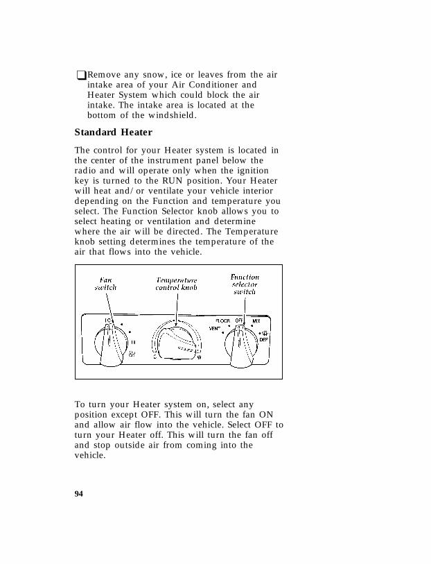
94
*[IP01499(B F )05/94] ❑Remove any snow, ice or leaves from the airintake area of your Air Conditioner andHeater System which could block the airintake. The intake area is located at thebottom of the windshield.
*[IP01500(B F )05/94] Standard Heater
*[IP01505(B F )05/94] The control for your Heater system is located inthe center of the instrument panel below theradio and will operate only when the ignitionkey is turned to the RUN position. Your Heaterwill heat and/or ventilate your vehicle interiordepending on the Function and temperature youselect. The Function Selector knob allows you toselect heating or ventilation and determinewhere the air will be directed. The Temperatureknob setting determines the temperature of theair that flows into the vehicle.
*[IP01510(B F )05/94]
one third page art:0020096-D
*[IP01515(B F )05/95] To turn your Heater system on, select anyposition except OFF. This will turn the fan ONand allow air flow into the vehicle. Select OFF toturn your Heater off. This will turn the fan offand stop outside air from coming into thevehicle.
File:ltipb.exUpdate:Fri Jun 9 15:29:43 1995

95
*[IP01520(B F )03/95] Temperature selection
*[IP01525(B F )02/95] The Temperature knob is the rotating knoblocated at the center of the control with taperedRED and BLUE bands surrounding most of theknob. The wide RED part of the band (full right)is the heat or warmer area. The wide BLUE area(full left) is the cool or unheated temperaturearea. Any position selected between full rightand full left will give a temperature between thetwo extreme temperatures. The cool temperatureyou select will not be cooler than the outsidetemperature.
*[IP01530(B F )03/95] H Fan speed adjustment
*[IP01535(B F )05/94] The H knob on the control is the fan speedknob which controls the volume of air flow.Rotate the H knob to the right to increase fanspeed and increase the amount of of air enteringthe vehicle. Four fan speed positions areavailable and are indicated by LO, two separatedots and HI beside the H control knob. The HIposition provides the most air flow.
*[IP01540(B F )03/95] Air flow selections
*[IP01542(B F )03/95] VENT
*[IP01545(B F )02/95] Use VENT to bring outside air through theinstrument panel registers. You can heat the airin this position by rotating the temperature knobinto the RED area. The air CANNOT be cooledbelow the outside temperature regardless of thetemperature knob setting.
*[IP01550(B F )03/95] FLOOR
*[IP01555(B F )05/94] Air flow will be to the floor when FLOOR isselected. The air can be heated by rotating thetemperature knob into the RED area.
File:ltipb.exUpdate:Fri Jun 9 15:29:43 1995

96
*[IP01560(B F )03/95] MIX
*[IP01563(B F )05/94] Select MIX to get air to the floor and windshielddefrosters at the same time.
*[IP01565(B F )03/95] V DEF
*[IP01570(B F )04/95] Select V DEF to obtain maximum air flow tothe windshield. Rotate the temperature knob intothe RED area for the air temperature required todefrost. Rotate the H knob to increase ordecrease the air flow.
*[IP01575(B F )05/94] Operating Tips
*[IP01580(B F )02/95] The following tips will help you to get the mostsatisfaction from your heater system.
[IP01585(B F )04/95] ❑ In humid weather, select V DEF. This willhelp to prevent windshield fogging. After afew minutes, you may select another airflowposition.
*[IP01587(B F )02/95] ❑To prevent humidity buildup inside yourvehicle, always drive with the heater systemturned on.
[IP01590(B F )02/95] ❑Do not put objects under the front seats thatwill interfere with the flow of air under theseats to the back seat area of your vehicle.
*[IP01595(B F )02/95] ❑Remove any snow, ice, or leaves from the airintake area at the bottom of the windshield.
File:ltipb.exUpdate:Fri Jun 9 15:29:43 1995

97
*[IP03901(B F )05/94]
one third page art:0020096-D
Climate control knobs (heater only)
*[IP12300(B )08/93] Rear Window Defroster(If equipped)(Standard in Canada)
*[IP12400(B )12/91] The defroster for the rear window clears frost,fog, or thin ice from both the inside and outsideof the rear window.
*[IP12550(B )04/95] The control switch is located on the instrumentpanel to the right of the steering column.
[IP12650(B )05/91]
quarter page art:0020887-A
Rear window defroster switch
*[IP12800(B )02/95] To defrost the rear window:
*[IP12900(B )02/95] 1. Clear any snow from the rear window.
*[IP13000(B )02/95] 2. Get in your vehicle and start the engine.
*[IP13150(B )03/95] 3. Press the switch. The indicator light shouldturn on.
File:ltipb.exUpdate:Fri Jun 9 15:29:43 1995

98
*[IP13300(B )02/05] The defroster turns off automatically afterapproximately 10 minutes. If the window is notclear, turn on the defroster again. It will alsoautomatically shut off any time the engine isshut off.
%*[IP13400(B )03/94] NOTE: Never use sharp instruments orwindow cleaners with abrasives toclean the inside of your rear window.If you do, you may damage the heatingelements that are bonded to the insideof the rear window and cause damageto the rear window defroster.
*[IP16800(BEF )01/95] The Interior and Exterior Lights
*[IP16900( ALL)01/95] Turning On the Exterior Lights
*[IP17000( ALL)02/95] To turn on your headlamps, parking lamps,marker lamps, and tail lamps, use the headlampswitch to the left of the steering column.
*[IP17100( ALL)06/94] 1. Pull the headlamp control knob toward youto the first position. Parking lamps, taillamps and marker lamps are now on.
*[IP17200( ALL)06/94] 2. Pull the headlamp control knob toward youto the outer position. Headlamps are now onin addition to the above.
*[IP17250(BEF )02/95] 3. Rotate the knob when it is in an on positionto brighten or dim the instrument panellamps. Rotate fully counterclockwise tooperate courtesy and cargo lamps.
File:ltipb.exUpdate:Fri Jun 9 15:29:43 1995

99
*[IP17260(B FM)10/92]
half page art:0020122-F
Headlamp switch
%*[IP17400(BEF )05/95] Cleaning the Exterior Lamps
*[IP17500(BEF )05/95] Do not use dry paper towel, chemical solventsor abrasive cleaners to clean the lamps, as thesemay cause scratches or crack the lamps.
*[IP17815( ALL)01/95] Daytime Running Light System
*[IP17820( ALL)03/95] (Canadian vehicles only)
*[IP17830( ALL)03/95] The Daytime Running Light (DRL) system turnsthe high beam headlamps on, with a reducedlight output, when:
*[IP17835( ALL)03/95] ❑The headlamp system is in the OFF position,and
*[IP17840( ALL)03/95] ❑The vehicle is running, and
*[IP17850( ALL)01/95] ❑The vehicle has a fully released parkingbrake.
File:ltipb.exUpdate:Fri Jun 9 15:29:43 1995

100
*[IP17875( ALL)01/95] NOTE: You may notice that the lights flickerwhen the vehicle is turned on or off.This is a normal condition.
*[IP17890(BEF )05/95] RWARNING
The Daytime Running Light (DRL) systemwill not illuminate the tail lamps andparking lamps. Turn on your headlampsat dusk. Failure to do so may result in acollision.
*[IP17900(BEF )03/95] Lighting Up the Instrument Panel and theInterior of Your Vehicle
*[IP18000(BEF )03/95] The instrument panel lights can be turned on bypulling the headlamp switch toward you toeither the first or outer position. You canbrighten or dim the instrument panel lights byrotating the headlamp switch knob.
%*[IP18400(BEF )03/95] Cargo, Courtesy and Dome Lamps
*[IP18700(BE )12/91] Rear cargo lamps, equipped with anON/OFF/DOOR switch will light when thedoors are closed and the switch is in the ONposition.
*[IP19000(BE )05/95]
quarter page art:0020125-B
Rear cargo lamp with rear headliner
*[IP19175(B F )05/90] The interior/courtesy lamp is automaticallyturned on when the driver or passenger door isopened. Turning the headlamp switch fullycounterclockwise will operate the interior lampwhen the doors are closed.
File:ltipb.exUpdate:Fri Jun 9 15:29:43 1995

101
*[IP19185(B F )05/95]
quarter page art:0020695-A
Interior/Courtesy lamp
*[IP19190(B F )05/95] Combination Cargo and High-MountBrakelamp
*[IP19200(B F )05/95] The combination cargo/high-mount brakelamp islocated outside the vehicle, directly over the rearwindow. Use the headlamp control switch toturn on the cargo lamp and interior courtesylights.
[IP19375(B )07/93]
quarter page art:0021013-B
Cargo/High-mount brakelamp
*[IP19400(B F )05/91] RWARNING
Do not drive your vehicle with thecargo/courtesy light on. Showing a whitelight to the rear while driving on publicroads is illegal in some places.
File:ltipb.exUpdate:Fri Jun 9 15:29:43 1995

102
*[IP19705(B F )07/94] Turning On the Dome/Map ReadingLamps (If equipped)
*[IP19805(B F )07/94] The map lamps are located inside the dome lightassembly, on each side of the dome light. Eachlamp has its own switch.
[IP19820(B )03/93] If you have the Bronco Eddie Bauer, the maplamps are located in the overhead console. Eachlamp has its own switch.
[IP19885(B )05/94]
one third page art:0021077-B
Map lamps — Eddie Bauer only
*[IP19900(B F )05/94]
quarter page art:0020127-B
Map lamps
File:ltipb.exUpdate:Fri Jun 9 15:29:43 1995

103
%*[IP20060(BEF )04/95] Cleaning the Instrument Panel Lens
*[IP20070(BEF )04/95] Clean the instrument panel lens with a soft clothand a glass cleaner, such as Ford Ultra-ClearSpray Glass Cleaner, or equivalent. Do not usepaper towel or an abrasive cleaner to clean thelens as these may cause scratches.
%*[IP20075(BEF )04/95] Cleaning the Interior Lamps
*[IP20080(BEF )04/95] Your interior dome lamps and map lamps areplastic and should be cleaned with a milddetergent diluted in water. Rinse them with clearwater.
File:ltipb.exUpdate:Fri Jun 9 15:29:43 1995
105
Steering Column Controls
*[SC00400( ALL)01/95] The controls on the steering column and wheelare designed to give you easy access to thecontrols while you are driving.
*[SC00500( ALL)01/95] The Turn Signal Lever
*[SC00600( ALL)01/95] You can use the turn signal lever on the left sideof the steering column to:
*[SC00700( ALL)03/95] ❑operate the turn signals and cornering lamps
*[SC00800(BEF )01/95] ❑ turn the high beams on/off
*[SC00900(BEF )01/95] ❑ flash the lights
*[SC01000(BEF )01/95] ❑ turn the windshield wipers and washeron/off
*[SC01100( ALL)01/95] Turn Signals
*[SC01200( ALL)03/95] Move the lever up to signal a right turn. Moveit down to signal a left turn. The correspondingindicator light in the instrument cluster willflash.
*[SC01400( ALL)03/95] If the turn signal stays on after you turn, movethe lever back to the center (off) position.
File:ltscb.exUpdate:Fri Jun 9 15:29:08 1995

106
*[SC01700( ALL)01/94]
one third page art:0020081-C
Turn signal lever and functions
*[SC01800( ALL)11/89] If the turn indicator light in the instrumentpanel does not illuminate or remains on (doesn’tflash) when you signal a turn, the turn signalingsystem is malfunctioning. Have this conditioncorrected as soon as possible, but make sure thatyou use the accepted hand signals in themeantime.
*[SC03200( ALL)03/95] High Beams
*[SC03300( ALL)05/95] To turn on the high beams, turn the headlampcontrol knob to the headlamp ON position andpush the turn signal lever away from you untilit latches. When the high beams are ON, thehigh beam indicator light on the instrumentpanel comes on.
*[SC03400( ALL)03/95] To turn off the high beams, pull the levertoward you until it latches. The high beamindicator light turns off.
File:ltscb.exUpdate:Fri Jun 9 15:29:08 1995

107
*[SC03800( ALL)03/95]
one third page art:0020074-B
Headlamp high beam switch and turn signal lever
*[SC04200( ALL)05/95] Flashing the Lights
*[SC04300( ALL)05/95] To flash the headlamps, pull the lever towardyou for a moment and then release it. Theheadlamps will flash whether the headlampknob is on or off.
*[SC04400( ALL)03/95] Windshield Wipers and Washer
*[SC04500( ALL)03/95] To turn on the windshield wipers, the ignitionkey must be turned to the ON or ACC position.
*[SC04600( ALL)03/95] Turn the knob on the end of the turn signallever toward the front of the vehicle. You canturn it to either the LO or HI speed position.
*[SC04700( ALL)03/95] Variable Interval Wipers
*[SC04800( ALL)03/95] In addition to two speed wipers, your vehicle isequipped with wipers that you can set tooperate at varying intervals. For example, youcan set the interval so they wipe less often whenit drizzles or more often in heavier rain.
File:ltscb.exUpdate:Fri Jun 9 15:29:08 1995

108
*[SC04950( ALL)10/92]
one third page art:0020831-A
Interval wiper on turn signal lever
*[SC05000( ALL)02/95] To set the interval wipers, rotate the knob at theend of the turn signal lever toward or awayfrom the instrument panel to the intervaloperation you desire.
*[SC05100( ALL)04/95] Windshield Washer
*[SC05200( ALL)03/95] To clean the windshield, push in the end of thewiper knob. For a constant spray, keep the knobpushed in. After you release the knob, thewipers operate for two to three cycles beforeturning off (if wipers were off) or returning toHI, LO, or the interval setting selected.
*[SC05300( ALL)01/95] Do not try to clean the windshield when thewasher fluid container is empty or activate thewashers at any time for more than 15 secondscontinuously. This could damage the washerpump system.
File:ltscb.exUpdate:Fri Jun 9 15:29:08 1995

109
*[SC05400( ALL)01/93] RWARNING
In freezing weather, the washer solutionmay freeze on the windshield and obscureyour vision. Always warm up thewindshield with the defroster before youuse the washer fluid. If you cannot seethrough the windshield clearly, it canincrease the risk of being involved in acollision.
*[SC05500(BEF )04/95] For information about refilling the washer fluidor replacing your windshield wiper blades, seeWindshield washer fluid and Wipers in the Index.
%*[SC05510( ALL)03/95] Hazard Flasher
*[SC05520( ALL)04/95] The hazard flasher is used to alert other driversto hazardous situations.
*[SC05527(BE )10/94] The flashers will flash and the high-mountbrakelamp will stay on steadily (not flash) withthe brake pedal depressed.
*[SC05530( ALL)03/95] The flashers work whether your vehicle isrunning or not. The flashers work for up to twohours when the battery is fully charged and ingood condition without draining the batteryexcessively. If the flashers run for longer thantwo hours or if the battery is not fully charged,the battery can be drained.
*[SC05540( ALL)09/93] To use the hazard flasher:
*[SC05550( ALL)10/92] 1. Push in the flasher button; it will pop outand the lamps will begin to flash.
*[SC05560( ALL)10/92] 2. To stop the flashers, push in the flasherbutton again.
*[SC05562( ALL)10/92] NOTE: The flasher button will be sticking upslightly higher when ON than whenOFF.
File:ltscb.exUpdate:Fri Jun 9 15:29:08 1995
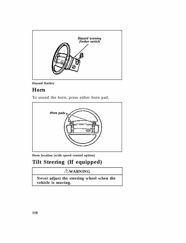
110
*[SC05575(BEF )06/93]
one third page art:0020075-B
Hazard flasher
*[SC05600( ALL)01/95] Horn
*[SC05800(BEF )05/95] To sound the horn, press either horn pad.
*[SC06150(BEF )06/93]
one third page art:0020086-B
Horn location (with speed control option)
*[SC06200(BEF )05/95] Tilt Steering (If equipped)
*[SC06300(BEF )05/95] RWARNING
Never adjust the steering wheel when thevehicle is moving.
File:ltscb.exUpdate:Fri Jun 9 15:29:08 1995
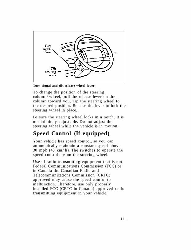
111
*[SC06500(BEF )01/94]
one third page art:0020089-C
Turn signal and tilt release wheel lever
*[SC06700( ALL)04/95] To change the position of the steeringcolumn/wheel, pull the release lever on thecolumn toward you. Tip the steering wheel tothe desired position. Release the lever to lock thesteering wheel in place.
*[SC07250( ALL)12/89] Be sure the steering wheel locks in a notch. It isnot infinitely adjustable. Do not adjust thesteering wheel while the vehicle is in motion.
*[SC07300(BEF )03/91] Speed Control (If equipped)
*[SC07450( ALL)05/95] Your vehicle has speed control, so you canautomatically maintain a constant speed above30 mph (48 km/h). The switches to operate thespeed control are on the steering wheel.
*[SC07500( ALL)05/95] Use of radio transmitting equipment that is notFederal Communications Commission (FCC) orin Canada the Canadian Radio andTelecommunications Commission (CRTC)approved may cause the speed control tomalfunction. Therefore, use only properlyinstalled FCC (CRTC in Canada) approved radiotransmitting equipment in your vehicle.
File:ltscb.exUpdate:Fri Jun 9 15:29:08 1995

112
*[SC07700(BEF )05/95]
quarter page art:0020093-B
The speed control switches
*[SC07800( ALL)03/95] To set the speed control:
*[SC08000( ALL)03/95] 1. Press and release the ON switch.
*[SC08100( ALL)04/95] 2. Accelerate to the desired speed above30 mph (50 km/h) using the acceleratorpedal.
*[SC08400( ALL)03/95] 3. Press the SET ACCEL switch and release itimmediately to set your speed. If you keepthis switch pressed, your speed will continueto increase.
*[SC08500( ALL)03/95] 4. Take your foot off the accelerator pedal.Your vehicle will maintain the speed you set.
*[SC08600( ALL)01/95] If you drive up or down a steep hill, yourvehicle may momentarily slow down or speedup, even though the speed control is on. This isnormal.
*[SC08640( ALL)04/95] NOTE: If your speed increases above your setspeed while driving in j (Overdrive)on a downhill grade, you may want todepress the transmission control switchlocated on the shift lever to turn offoverdrive to reduce vehicle speed.Speed control cannot reduce the vehiclespeed if it goes above your set speedon a downhill grade. For the best fueleconomy during normal drivingconditions, leave the shift select in j(Overdrive), or resume as soon aspractical.
File:ltscb.exUpdate:Fri Jun 9 15:29:08 1995
113
*[SC08700( ALL)05/95] RWARNING
Do not use the speed control in heavytraffic or on roads that are winding,slippery, or unpaved.
*[SC08801( ALL)03/91] In mountainous areas, at higher elevations, orwhen pulling a trailer, the speed control maynot be able to maintain the preset speed withthe transmission in overdrive.
*[SC08850(B F )06/92] If your vehicle comes with a 5-speed manualtransmission, you may prefer to drive in 4(Fourth) gear, in mountainous areas or at highaltitudes, to improve speed control performance.
*[SC09275(B F )12/91] In order to downshift (with a manualtransmission) with the speed control operating,you must press either the brake or clutch pedallong enough to disengage the speed control.Wait a second before depressing the clutch againand making the shift so that the speed controlcan fully return to the idle position.
*[SC09325( ALL)05/95] RWARNING
Do not shift the transmission into N(Neutral) with the speed control on.
*[SC09350( ALL)03/94] To maintain a preset speed under the aboveconditions, with electronically controlledtransmissions — press the Transmission ControlSwitch. The indicator light will turn on andilluminate the word “OFF.” This will cancel“Overdrive”. You can press the TransmissionControl Switch on or off at any speed. For thebest fuel economy during normal drivingconditions, press the Transmission ControlSwitch to turn off the light. This allowsoverdrive operation.
File:ltscb.exUpdate:Fri Jun 9 15:29:08 1995

114
*[SC09375( ALL)05/95]
quarter page art:0020771-C
Transmission control switch and Indicator light
%*[SC09400( ALL)03/95] Accelerating With the Speed ControlOperating
*[SC09500( ALL)03/95] You can use the accelerator pedal to speed upmomentarily. When you take your foot off theaccelerator, the vehicle will return to the setspeed.
%*[SC09600( ALL)01/95] Resetting the Speed Control
*[SC09700( ALL)03/95] To reset the speed control to a lower speed,press and hold the COAST switch. Let yourvehicle slow down to the desired speed andrelease the COAST switch.
*[SC09750( ALL)10/94] Your vehicle has a “tap-down” feature thatallows you to decrease your current speed inincrements of 1 mph (1.6 km/h) by amomentary tap of the COAST switch. Multipletaps of the COAST switch will decrease yourvehicle speed 1 mph (1.6 km/h) for each tap.For example, if you are currently set at 65 mph(104 km/h) and tap the COAST switch 5 timesyour vehicle speed will decrease and set at60 mph (96 km/h).
*[SC09800( ALL)03/91] To reset the speed control to a higher speed,you can follow any of these procedures:
*[SC10000( ALL)03/95] ❑Accelerate to the desired speed using theaccelerator pedal, then press the SET ACCELswitch and release it immediately.
File:ltscb.exUpdate:Fri Jun 9 15:29:08 1995

115
*[SC10200( ALL)03/95] ❑Press and hold the SET ACCEL switch untilthe vehicle accelerates to the desired speed,then release the switch.
*[SC10250(BEF )10/94] ❑TAP-UP — This allows you to increase yourcurrent speed in increments of 1 mph(1.6 km/h) by a momentary tap of theSET-ACCEL switch. Multiple taps of theSET-ACCEL switch will increase your vehiclespeed 1 mph (1.6 km/h) for each tap. Forexample, if you are currently set at 60 mph(96 km/h) and tap the SET-ACCEL switch 5times your vehicle speed will increase and setat 65 mph (104 km/h).
*[SC10300( ALL)12/91] Turning the Speed Control Off
*[SC10400( ALL)03/95] You can cancel the speed control while you aredriving.
*[SC10500( ALL)06/92] ❑Press the OFF switch. The speed control isoff. If you want to resume speed control,press the ON switch and reset the speedcontrol by pressing the SET ACCEL button.
[SC10700(B F )04/95] ❑Press the clutch pedal slightly (if equipped).The speed control is suspended, but you canreset it by pressing SET ACCEL or return tothe previous set speed with the RESUMEswitch.
[SC10750( ALL)04/95] ❑Press the brake pedal slightly. The speedcontrol is suspended, but you can reset it bypressing SET ACCEL or return to theprevious set speed with the RESUME switch.
*[SC10800( ALL)04/95] In addition, the speed control is turned off eachtime you turn the vehicle off.
File:ltscb.exUpdate:Fri Jun 9 15:29:08 1995

116
*[SC11100( ALL)11/89] Driving uphill or on a steep grade
*[SC11200( ALL)05/95] When the speed control is on, your vehicle maysignificantly drop speed when driving uphill,especially with a heavy load. If the speed dropsmore than 8 to 14 mph (15 - 25 km/h) theautomatic speed control will, by design, becanceled. You may have to temporarily resumemanual speed control while driving up a steepgrade in order to maintain the speed you desire.
*[SC11250( ALL)03/93] Frequent shifting of an automatic transmission orspeed loss during speed control operation can beeliminated by shifting out of overdrive intodrive (or by pressing the Transmission ControlSwitch, if equipped). These conditions couldoccur in hilly terrain or at higher elevations.
*[SC11400( ALL)12/91] If the speed control “dropped out” after yourclimb is completed, the speed of your vehiclecan be reset with the SET ACCEL switch, orreturned to the previous set speed with theRESUME switch, as long as you are driving over30 mph (48 km/h).
File:ltscb.exUpdate:Fri Jun 9 15:29:08 1995

117
%*[SC11500( ALL)03/95] Cancelling and Resuming a Set Speed
*[SC11600( ALL)07/94] If you press the brake pedal, the speed control iscancelled. You can return to the speed you setby using the RSM switch, as long as you did notpress the OFF switch.
*[SC11700( ALL)05/95] To resume the speed you had before, you mustbe driving at least 30 mph (50 km/h).
*[SC11800( ALL)11/94] Press and release the RESUME switch. Yourvehicle gradually returns to the previously setspeed and then maintains it.
*[SC11850( ALL)03/95] RWARNING
If your vehicle has speed control, do notuse it on slippery roads. You could losecontrol of your vehicle and could injuresomeone.
File:ltscb.exUpdate:Fri Jun 9 15:29:08 1995

119
Features
*[FV00401(BEF )02/95] Your vehicle has a variety of features designedfor your comfort, convenience and safety. Readthis chapter to find out about standard andoptional features.
*[FV00601(BEF )01/95] Doors%*[FV01801(BEF )03/95] Anti-theft front door lock knobs
*[FV01901(BEF )10/89] Anti-theft lock knobs are designed to precludeunlocking the door by pulling up on the bullettype lock knob. To unlock and open the frontdoor from the inside of the vehicle, pull on theinside door handle.
*[FV06001(B F )05/90] Tailgate
[FV06101(B )05/90] To open the tailgate, first lower the tailgatewindow.
[FV06201(B )05/90] Next, lift the latch handle from the insidetailgate panel of your vehicle, and lower thetailgate.
[FV06300(B )05/90] To close the tailgate, lift it and push forwardwith enough force to latch the assembly securelyin position.
*[FV06601(B F )05/90] When open, the tailgate load should not exceed500 lbs (227 kgs). If you want to load heavyitems onto your vehicle, Ford recommends thatyou load them one at a time, directly on the bedfloor to avoid damage to the tailgate or itssupports.
File:ltfvb.exUpdate:Fri Jun 9 15:28:41 1995

120
[FV06701(B )05/90] For trucks with a swing away spare tire carrier,you must release the carrier and swing it out ofthe way before lowering the tailgate. See thefollowing illustration.
[FV06801(B )05/90]
one third page art:0020193-B
Bronco tailgate operation
[FV06901(B )05/90] Latch lockout system for the tailgate
[FV07001(B )05/90] The tailgate is equipped with a latch lockoutsystem which prevents you from opening itunless the glass is completely down. The lockoutalso prevents the glass from being raised unlessthe tailgate is completely latched in the closedposition.
[FV07101(B )05/90] RWARNING
When driving your vehicle make sure thatthe tailgate door and window are closedto prevent exhaust fumes from beingdrawn into the vehicle. This will alsoprevent passengers and cargo from fallingout.
File:ltfvb.exUpdate:Fri Jun 9 15:28:41 1995

121
[FV07201(B )02/92] If you must drive with the rear window open:
[FV07301(B )03/95] ❑Adjust your climate control system to forceoutside air into your vehicle.
[FV07401(B )02/92] ❑Completely open the outside air vents if yourvehicle is so equipped.
[FV07501(B )02/92] ❑You can prevent the tailgate from accidentallyopening by raising the glass one inch fromthe fully opened position.
*[FV14100(BEF )04/95] Power Door Locks (If equipped)
*[FV14500(BEF )05/95] The power door lock switches are located in thefront doors. To lock all doors push the switchmarked L. To unlock all doors push the switchmarked U.
*[FV14701(BEF )03/91] The manual door locks will override the powerdoor lock controls.
*[FV15001(BEF )05/95]
quarter page art:0020203-C
Power door lock controls
*[FV15301(BEF )02/95] Remote Entry System(If equipped)
*[FV15401(BEF )06/94] If your vehicle has the remote entry system, youcan lock or unlock the vehicle doors withoutusing a key. The remote also has a personalalarm feature. The buttons for the system arelocated on the two hand held transmitters thatcame with your vehicle.
File:ltfvb.exUpdate:Fri Jun 9 15:28:41 1995

122
*[FV15600(BEF )02/95] The system will work with up to fourtransmitters. Your vehicle came with twotransmitters. Additional transmitters can beordered from your dealer.
*[FV15700(BEF )02/95] The remote entry features only operate with theignition in the OFF position.
*[FV15800(BEF )04/94]
quarter page art:0020788-A
The remote entry transmitter
%*[FV15901(BEF )02/95] Unlocking the doors with the remote entrysystem
*[FV16001(BEF )02/95] To unlock the driver’s door, press the UNLOCKbutton.
*[FV16101(BEF )02/95] To unlock the other doors, press the UNLOCKbutton a second time within five (5) seconds ofunlocking the driver’s door.
*[FV16300(BEF )02/95] Locking the doors with the remote entrysystem
[FV16500(B F )04/95] To lock all the doors, press the LOCK button.
*[FV16600(B F )03/93] If you would like a signal that the doors arebeing locked, press the LOCK button againwithin five seconds. The door will lock again,the horn will beep, and the external lamps willflash.
%*[FV16800(BEF )02/95] Remote entry personal alarm
*[FV16900(BEF )04/95] If you wish to activate the remote entry systempersonal alarm, press the PANIC button. Thiswill honk the horn and flash the lights for
File:ltfvb.exUpdate:Fri Jun 9 15:28:41 1995

123
approximately 2 minutes 45 seconds. You canturn it OFF by pressing the PANIC button againfrom the same transmitter or by turning theignition to the ON or ACCESSORY position.
*[FV17000(BEF )02/95] When you use the remote entry UNLOCK orPANIC buttons, the illuminated entry systemturns on the vehicle’s interior lights for 25seconds. You can turn these lights off with theremote entry LOCK button or by turning theignition to the ON or ACCESSORY position.
*[FV17100(BEF )04/94]
quarter page art:0060566-B
%*[FV17501(BEF )02/95] Replacing the batteries
*[FV17601(BEF )02/95] The remote entry transmitter is powered by twocoin type three-volt lithium 2016batteries (included) that should last for severalyears of normal use. If you notice a significantdecrease in operating range, the batteries shouldbe replaced. Replacement batteries can bepurchased at most pharmacies, watch stores orat your Ford or Lincoln-Mercury dealer.
*[FV17701(BEF )02/95] NOTE: The operating range of the remoteentry system can also be affected byweather conditions (such as very coldtemperatures) or structures around thevehicle (buildings, other vehicles, radioand TV towers, etc.). Typical operatingrange will allow you to be up to 33feet (10 meters) away from yourvehicle.
File:ltfvb.exUpdate:Fri Jun 9 15:28:41 1995
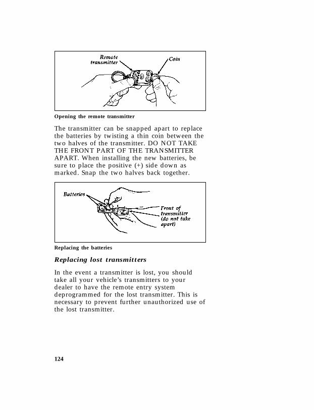
124
*[FV17801(BEF )03/93]
quarter page art:0020789-A
Opening the remote transmitter
*[FV17901(BEF )02/95] The transmitter can be snapped apart to replacethe batteries by twisting a thin coin between thetwo halves of the transmitter. DO NOT TAKETHE FRONT PART OF THE TRANSMITTERAPART. When installing the new batteries, besure to place the positive (+) side down asmarked. Snap the two halves back together.
*[FV18001(BEF )02/95]
quarter page art:0020790-A
Replacing the batteries
%*[FV18101(BEF )02/95] Replacing lost transmitters
*[FV18200(BEF )02/95] In the event a transmitter is lost, you shouldtake all your vehicle’s transmitters to yourdealer to have the remote entry systemdeprogrammed for the lost transmitter. This isnecessary to prevent further unauthorized use ofthe lost transmitter.
File:ltfvb.exUpdate:Fri Jun 9 15:28:41 1995

125
*[FV18301(BEF )02/95] You can also purchase additional transmitters(up to 4 transmitters can be used) from yourdealer. You will need to take all yourtransmitters to the dealer so they can programthem to the remote entry system all at the sametime.
*[FV18601(BEF )04/95] Illuminated Entry System (If equipped)
[FV18701(BEF )04/95] This system will provide illumination of thevehicle’s interior courtesy lamps when eitheroutside front door handle is pulled or when theRemote Entry System is used to unlock the dooror sound the Personal Alarm. The system willautomatically turn off after approximately 25seconds or when the ignition is turned to theSTART or ACCESSORY position.
*[FV18801(BEF )04/94] NOTE: The inside lights will not turn off ifyou have turned them on with thedimmer knob or if any door is open.
*[FV18900(B F )04/94] Battery Saver (with Remote Entry — Ifequipped)
*[FV19000(B F )03/95] When the ignition is turned off, the vehicle willturn off battery voltage to all of these lights after40 minutes: glove box, engine compartment,overhead console, mirror, courtesy andinterior (including cargo) lamps.
*[FV19102(B F )03/95] This will prevent draining of the battery if theselights have been left on inadvertently or if adoor is not completely closed. Battery voltage tothese lamps will be restored when the remoteentry transmitter is used, any door is opened, orthe ignition key is turned on again.
File:ltfvb.exUpdate:Fri Jun 9 15:28:41 1995

126
*[FV19250(BEF )02/95] Windows[FV22000(B )05/90] Tailgate Window
[FV22101(B )05/91] The switch to operate the tailgate window is onthe instrument panel to the left of the steeringcolumn next to the master lighting switch. Withthe ignition in the ON or ACC position, movethe switch down to lower the window and moveit up to raise the window. You can also operatethe tailgate window by using the key from theoutside of the tailgate.
[FV22201(B )05/90] RWARNING
When driving your vehicle make sure thatthe tailgate door and window are closedto prevent exhaust fumes from beingdrawn into the vehicle. This will alsoprevent passengers and cargo from fallingout.
[FV22301(B )02/92] If you must drive with the rear window open:
[FV22401(B )03/95] ❑Adjust your climate control system to forceoutside air into your vehicle.
[FV22501(B )02/92] ❑Completely open the outside air vents if yourvehicle is so equipped.
[FV22601(B )02/92] ❑You can prevent the tailgate from accidentallyopening by raising the glass one inch fromthe fully opened position.
File:ltfvb.exUpdate:Fri Jun 9 15:28:41 1995

127
[FV22701(B )03/91]
quarter page art:0020215-B
Rear window switch
[FV22801(B )02/89] When driving in extremely dusty areas, clean thetailgate glass periodically to prevent build-up ofsurface dust. This will prevent excessive wear ordamage to the tailgate window seals.
*[FV22901(BEF )03/91] Using the Power Windows (If equipped)
*[FV23001(BEF )05/90] Each door has a power control that opens andcloses the window on that door. The driver’sdoor has a master control switch that operatesboth front door windows. You must place theignition switch in the ON or ACC position touse your power window controls.
*[FV23501(BEF )05/95] RWARNING
Do not let children play with the powerwindows. They may seriously hurtthemselves. Make sure occupants are clearof the window(s) before closing.
*[FV23800(BEF )05/95]
quarter page art:0020203-C
Master control switch
File:ltfvb.exUpdate:Fri Jun 9 15:28:41 1995
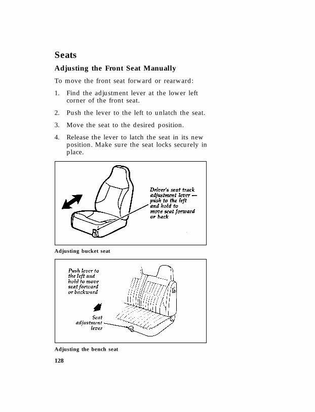
128
*[FV24101(BEF )01/95] Seats
*[FV24801(BEF )05/90] Adjusting the Front Seat Manually
*[FV24901(BEF )08/94] To move the front seat forward or rearward:
*[FV25001(BEF )08/94] 1. Find the adjustment lever at the lower leftcorner of the front seat.
*[FV25101(BEF )10/89] 2. Push the lever to the left to unlatch the seat.
*[FV25201(BEF )04/95] 3. Move the seat to the desired position.
*[FV25301(BEF )04/89] 4. Release the lever to latch the seat in its newposition. Make sure the seat locks securely inplace.
*[FV25600(B F )03/91]
one third page art:0020218-B
Adjusting bucket seat
*[FV25700(B F )05/95]
one third page art:0020220-E
Adjusting the bench seat
File:ltfvb.exUpdate:Fri Jun 9 15:28:41 1995

129
*[FV26001(BEF )05/95] RWARNING
Never adjust the driver’s seat or seatbackwhen the vehicle is moving.
*[FV26100(BEF )05/95] RWARNING
Do not pile cargo higher than theseatbacks to avoid injuring people in acollision or sudden stop.
*[FV26200(BEF )05/95] RWARNING
To reduce the risk of serious injury in acollision, always drive and ride with yourseatback upright and the lap belt snugand low across the hips.
*[FV26300(BEF )05/95] RWARNING
To reduce the risk of serious injury in acollision, children should always ride withthe seatback upright.
*[FV26400(BEF )10/89] Reclining Bucket Seats
*[FV27301(BEF )02/92] You can tilt the seat back of your bucket seatsbackward.
*[FV27401(B F )03/93] 1. On the outboard side of the seat, lift therecliner handle up and hold it in place.
*[FV27501(BEF )10/89] 2. Lean against the back of the seat and adjustit to the position you want.
*[FV27601(BEF )10/89] 3. Release the handle to lock the seat back inplace.
*[FV27701(BEF )10/89] 4. To return the seat back upright, lift thehandle and lean forward.
File:ltfvb.exUpdate:Fri Jun 9 15:28:41 1995

130
*[FV27800(B F )02/92]
one third page art:0020222-B
Reclining bucket seat
*[FV28001(B F )10/90] Lifting the seat-back adjustment lever of anunoccupied seat will allow the seat back to foldforward for access to the rear. Pushing the seatback backward with the handle released returnsthe seat upright.
*[FV30501(B F )01/89] Seat Back Release (Bench Seat)
[FV30801(B )12/91] The split back bench seat can be folded forwardon either side to gain access to the rear of thevehicle. To do so, push up the latch buttonlocated at the top of the seat back.
[FV31000(B )05/95]
one third page art:0020227-D
Seat back release
File:ltfvb.exUpdate:Fri Jun 9 15:28:41 1995

131
*[FV31101(B F )05/95] RWARNING
A seatback which is folded forward evena small degree may not lock properly inthe event of a sudden stop or collision.
[FV43500(B )01/89] Rear Flip Fold Seat
[FV43600(B )01/89] To fold the seat forward:
[FV43700(B )01/89] 1. The seat back latch is at the lower rear righthand side of the seat. Lift the latch handle tounlock the seat back.
[FV43800(B )03/90] 2. Fold the seat back over the seat cushionuntil it locks into place.
[FV43900(B )03/90] 3. Unlock the seat from the floor striker bylifting the seat latch handle at the center rearedge of the seat.
[FV44000(B )03/90] 4. Lift the seat and fold forward.
[FV44100(B )12/89] To remove and reinstall the rear flip-foldseat:
[FV44200(B )01/89] 1. Remove the torque rod by releasing it fromthe right hand floor bracket (by pushingforward and up).
[FV44300(B )01/89] 2. Remove the pin spring retainers and the pinsfrom both the floor brackets.
[FV44400(B )01/89] 3. Remove the seat assembly from your Bronco.Reverse this procedure to install the rearflip-fold seat.
[FV44500(B )05/90] NOTE: It is important that you do not damagethe seat belt hardware while removingor installing the rear flip-fold seat.
File:ltfvb.exUpdate:Fri Jun 9 15:28:41 1995

132
[FV44600(B )01/89]
half page art:0020238-A
Assembly for installing and removing the rear seat
*[FV45901(B F )05/93] Tilt Slide Seat
*[FV46020(B F )05/93] With the seatback tilted forward, the tilt slideseat can be moved forward to provide additionalentry space to access the rear seat compartmentof the vehicle.
*[FV46025(B F )05/94] To operate the tilt slide seat:
*[FV46030(B F )05/93] 1. Lift the seatback release lever on theoutboard side of the seat cushion to unlockthe slide mechanism and the seatback.
*[FV46035(B F )03/93] 2. Push the seat assembly forward to provideentry space to the rear seat compartment ofthe vehicle.
*[FV46043(B F )08/94] RWARNING
Do not place objects behind or under thefront seat which can prevent the seat fromreturning to the locked position.
File:ltfvb.exUpdate:Fri Jun 9 15:28:41 1995
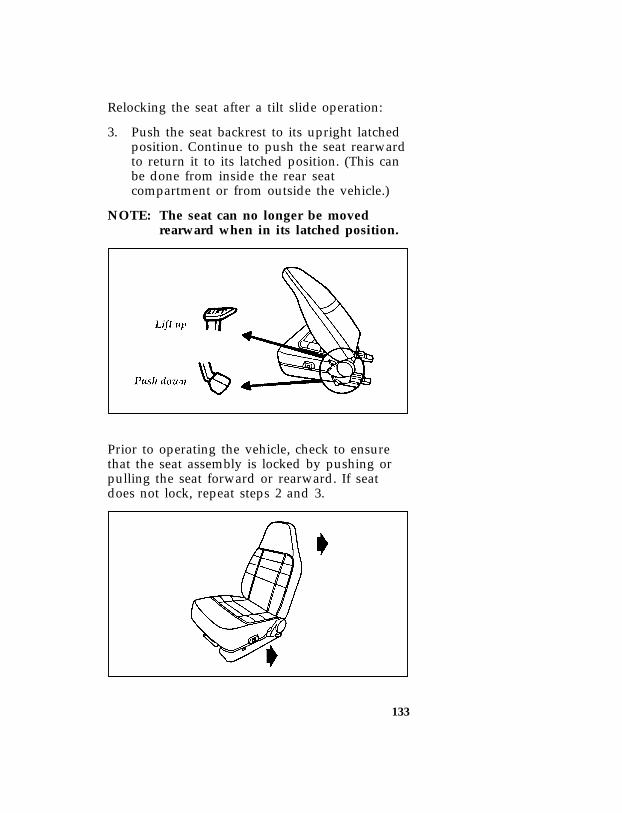
133
*[FV46045(B F )05/93] Relocking the seat after a tilt slide operation:
*[FV46051(B F )05/93] 3. Push the seat backrest to its upright latchedposition. Continue to push the seat rearwardto return it to its latched position. (This canbe done from inside the rear seatcompartment or from outside the vehicle.)
*[FV46053(B F )10/94] NOTE: The seat can no longer be movedrearward when in its latched position.
*[FV46055(B F )07/94]
one third page art:0021018-B
*[FV46065(B F )05/95] Prior to operating the vehicle, check to ensurethat the seat assembly is locked by pushing orpulling the seat forward or rearward. If seatdoes not lock, repeat steps 2 and 3.
*[FV46070(B F )07/94]
one third page art:0021019-B
File:ltfvb.exUpdate:Fri Jun 9 15:28:41 1995

134
*[FV46075(B F )03/93] To operate the seat adjuster:
*[FV46080(B F )05/93] 4. To adjust the seats forward or rearward,locate the release lever at the right lowerfront area of the seat cushion. Move therelease lever to the right and hold until thedesired seat position is obtained, then releasethe lever to relock the seat.
*[FV46085(B F )07/94]
one third page art:0021020-B
*[FV47000(BEF )03/94] Using the Power Lumbar Support and SideBolsters
*[FV47400(BEF )12/91] If your vehicle is equipped with this option, youcan inflate a lumbar support pad in the seatback. To inflate the lumbar pad, push the (+)side of the rocker switch. To deflate push the (-)side of the switch.
*[FV47500(BEF )06/92]
quarter page art:0020860-B
Power lumbar switch
File:ltfvb.exUpdate:Fri Jun 9 15:28:41 1995

135
*[FV47600(BEF )04/95] Cleaning the Seats
*[FV47620(BEF )05/95] Leather and vinyl
*[FV47625(BEF )05/95] For routine cleaning, wipe the surface with asoft, damp cloth. For more thorough cleaning,wipe the surface with a leather and vinyl cleaneror a mild soap.
*[FV47630(BEF )04/95] Wipe the surface with a damp, soft cloth, thendry and buff with a dry, soft cloth.
*[FV47640(BEF )04/95] Fabric
*[FV47650(BEF )04/95] Remove dust and loose dirt with a whisk broomor a vacuum cleaner. Remove fresh spotsimmediately. Follow the directions that comewith the cleaner.
*[FV47660(BEF )04/95] NOTE: Before using any cleaner, test it on asmall, hidden area of fabric. If thefabric’s color or texture is adverselyaffected by a particular cleaner, do notuse it.
*[FV50000(BEF )01/95] Mirrors
*[FV50200(BEF )03/91] With the door closed and the seat adjusted forcomfort and proper vehicle control, move themirrors for best view by tilting up or down, leftor right. Do not adjust the mirrors while thevehicle is in motion.
*[FV50325(BEF )05/95] RWARNING
Make sure you can see clearly through therearview mirror at all times. Do not allowanything to block your vision. If you can’tsee through the mirror, you could beinvolved in an accident and injureyourself or others.
File:ltfvb.exUpdate:Fri Jun 9 15:28:41 1995

136
%*[FV50700(B F )01/95] Automatic Dimming Inside RearviewMirror (If equipped)
*[FV50850(B F )03/93]
half page art:0021008-A
Automatic dimming inside rearview mirror
*[FV50900(B F )03/93] This mirror is equipped with an electrochromicglare control feature that automatically darkensthe mirror, reducing glare from the headlampsof vehicles behind you. A forward facing lightsensor measures the ambient light just as youreyes do. When the rear facing light sensor in theglass senses glare, such as from followingheadlights, it energizes a chemical layer in theglass causing it to darken and absorb light. Asthe glare subsides, the mirror glass returns to itsnormal clear state.
*[FV51050(B F )03/94] To turn the mirror on, push the On/Off switch,located on the bottom of the mirror, to latch itin the ON position. The button will be latched inthe up position and at night a low intensitygreen light will be visible from the button whenthe mirror is turned on. To turn the mirror off,
File:ltfvb.exUpdate:Fri Jun 9 15:28:41 1995

137
push the On/Off switch again and the buttonwill unlatch shutting off the light and the mirrorwill be off.
*[FV51100(B F )03/93] Demonstration — The mirror’s operation maybe demonstrated by simulating glare as follows:
*[FV51200(B F )03/94] 1. Cover the forward facing sensor, located onthe right side of the mirror back, with adark (preferably black) cloth. Hold the darkcloth over the sensor until you notice themirror glass start to darken to the non-glarestate. If the surrounding lighting conditionsare too dark it may be necessary to shineadditional lighting, such as from a flashlight,on the rearward sensor located on the glassface.
*[FV51400(B F )03/93] 2. Remove the cloth (and shut off the flashlightif applicable) and the glass will return to theclear reflective stage.
*[FV51500(B F )01/95] One important safety feature is that the mirrorautomatically returns to the normal positionwhenever the vehicle is placed in R (Reverse)(when the mirror is in the ON position). Thisfeature ensures a bright clear view in the mirrorwhen backing up.
*[FV52900(BEF )12/89] Outside Mirrors (Manual Control)
*[FV53000(BEF )10/89] Adjust outside mirrors with the door closed andthe seat adjusted for comfort and proper vehiclecontrol. Move the mirrors for best view bytilting up or down, left or right.
*[FV53100(BEF )03/95] On vehicles equipped with fold-away mirrors,the mirrors should be folded rearward into thebody position before entering automatic carwash systems.
File:ltfvb.exUpdate:Fri Jun 9 15:28:41 1995

138
*[FV53300(B F )12/91]
quarter page art:0020900-B
Standard fold-away mirror
[FV53800(B )05/90]
quarter page art:0020324-B
Low-mount swingaway mirror
*[FV54000(B )12/91] The right-hand side view mirror is convex. Thismirror has a curved surface and will show awider view of the lane next to and behind yourvehicle.
*[FV54400(BEF )05/95] RWARNING
The side view mirror on the right makesobjects appear smaller and farther awaythan they actually are.
File:ltfvb.exUpdate:Fri Jun 9 15:28:41 1995

139
*[FV54500(BEF )08/91] Dual Electric Remote Control Mirrors(If equipped)
*[FV54600(BEF )08/91] To adjust the remote controlled side mirrors:
*[FV54800(BEF )06/94] 1. Find the control switch in the driver’s doorpanel.
*[FV55000(BEF )06/94] 2. Select the right or left mirror by moving theselector switch to R or L.
*[FV55200(BEF )06/94] 3. Move the control knob in the direction youwant to move the mirror.
*[FV55400(BEF )06/94] 4. Return the selector switch to the middleposition to keep the mirror in place.
*[FV55700(B F )12/91]
quarter page art:0020886-A
Power mirror control
*[FV55900(BEF )12/91] Do not clean the plastic housing of any electricmirror with gasoline or other petroleum-basedcleaning products.
File:ltfvb.exUpdate:Fri Jun 9 15:28:41 1995

140
*[FV59400(BEF )01/95] Console
*[FV59500(BEF )12/91] Your vehicle may have a full console. The fullconsole has the features shown in the illustrationbelow.
*[FV60100(B F )12/91]
half page art:0020683-C
The features on the console
File:ltfvb.exUpdate:Fri Jun 9 15:28:41 1995

141
*[FV60200(B F )12/91]
three fourths page art:0020909-A
Seat mounted console
File:ltfvb.exUpdate:Fri Jun 9 15:28:41 1995

142
[FV60350(B )03/93] Overhead Console (Eddie Baueronly)
[FV60450(B )05/95] Your Eddie Bauer Bronco comes with anoverhead console located between the sun visors.The console includes:
*[FV60500(B )03/93] ❑Compass/temperature display
*[FV60600(B )03/93] ❑Map lamps
*[FV60700(B )03/93] ❑Storage compartment
*[FV60800(B )03/93] Compass/Temperature display
*[FV60900(B )05/95] This display provides the outside temperatureand the compass direction of the vehicle.
*[FV60920(B )03/93] The MODE button is used to select one of thefollowing features:
*[FV60940(B )03/93] ❑Display Off
*[FV60960(B )03/93] ❑Temp in ˚F and Compass
*[FV60980(B )03/93] ❑Temp in ˚C and Compass
[FV61001(B )05/95]
quarter page art:0020980-B
Compass/temperature display
[FV61100(B )03/93] Outside temperature display
*[FV61150(B )05/95] If the outside temperature is below 39˚F (4˚C),the word “ICE” will flash in the displayalternately with the outside temperature forabout one minute.
File:ltfvb.exUpdate:Fri Jun 9 15:28:41 1995

143
[FV61400(B )05/95] Electronic Compass
[FV61500(B )03/93] Factors affecting compass accuracy
*[FV61600(B )01/95] The compass reading can be affected when youdrive near a number of things — such as largebuildings, bridges, power lines, and powerfulantennas.
*[FV61700(B )05/95] Your compass can also be affected by magneticor metallic objects placed in or on the vehicle. Ifthe compass is giving inaccurate readings,perform the following compass adjustments.
[FV61800(B )03/93] Compass adjustments
*[FV61900(B )05/95] There are two possible adjustments to thecompass: Zone and Calibration.
[FV62050(B )05/95] Zone adjustment
*[FV62100(B )03/93] 1. Determine which zone of the country youare in by referring to the following zonemap.
File:ltfvb.exUpdate:Fri Jun 9 15:28:41 1995

144
[FV62200(B )03/93]
half page art:0080142-C
Zone map
*[FV62300(B )03/93] 2. Press and hold the “MODE” button until the“VAR” indicator appears in the display(approximately 4 seconds).
*[FV62400(B )03/93] 3. Release the “MODE” button. The displaywill now show the current zone number thatis stored in the compass.
*[FV62500(B )03/93] 4. Press the “MODE” button repeatedly (orpress and hold in) until the desired zonenumber appears in the display (once itreaches 15, the next press of the button willset it to 1).
*[FV62600(B )03/93] 5. Release the “MODE” button when thedesired zone number is displayed.
*[FV62700(B )05/95] After approximately three seconds the displaywill flash all segments and then return to normaloperation. Zone is now updated.
File:ltfvb.exUpdate:Fri Jun 9 15:28:41 1995
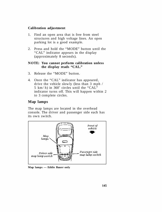
145
[FV62850(B )05/95] Calibration adjustment
*[FV62900(B )03/93] 1. Find an open area that is free from steelstructures and high voltage lines. An openparking lot is a good example.
*[FV63000(B )03/93] 2. Press and hold the “MODE” button until the“CAL” indicator appears in the display(approximately 8 seconds).
*[FV63050(B )05/95] NOTE: You cannot perform calibration unlessthe display reads “CAL.”
*[FV63100(B )03/93] 3. Release the “MODE” button.
*[FV63300(B )03/93] 4. Once the “CAL” indicator has appeared,drive the vehicle slowly (less than 3 mph /5 km/h) in 360˚ circles until the “CAL”indicator turns off. This will happen within 2to 3 complete circles.
*[FV63800(B )03/93] Map lamps
*[FV63900(B )03/93] The map lamps are located in the overheadconsole. The driver and passenger side each hasits own switch.
[FV64050(B )05/94]
one third page art:0021077-B
Map lamps — Eddie Bauer only
File:ltfvb.exUpdate:Fri Jun 9 15:28:41 1995
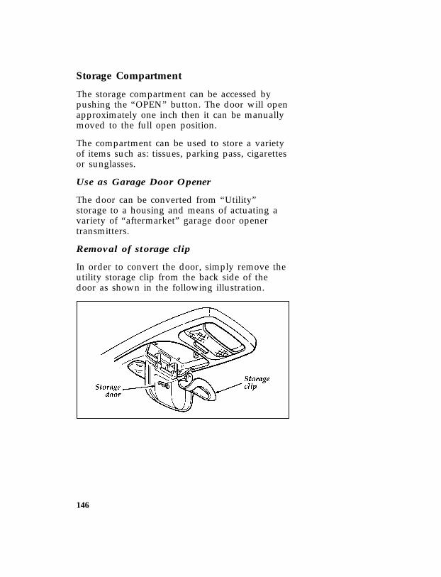
146
*[FV64100(B )03/93] Storage Compartment
*[FV64200(B )03/93] The storage compartment can be accessed bypushing the “OPEN” button. The door will openapproximately one inch then it can be manuallymoved to the full open position.
*[FV64300(B )03/93] The compartment can be used to store a varietyof items such as: tissues, parking pass, cigarettesor sunglasses.
*[FV64400(B )03/93] Use as Garage Door Opener
*[FV64500(B )03/93] The door can be converted from “Utility”storage to a housing and means of actuating avariety of “aftermarket” garage door openertransmitters.
*[FV64600(B )03/93] Removal of storage clip
*[FV64700(B )03/93] In order to convert the door, simply remove theutility storage clip from the back side of thedoor as shown in the following illustration.
[FV64850(B )05/93]
one third page art:0021079-A
File:ltfvb.exUpdate:Fri Jun 9 15:28:41 1995

147
*[FV64900(B )03/93] Installing “aftermarket” transmitter
*[FV65000(B )03/93] Place the piece of Velcro hook onto youraftermarket transmitter, opposite side as that ofthe actuator button.
*[FV65100(B )03/93] Place the transmitter into the console housing,button down, as shown. Place the heightadapters provided into the back side of the“GARAGE” button as needed. Some largertransmitters will not need the adapters, andsome smaller ones may need two adapters.
*[FV65200(B )03/93] The transmitter can now be activated withoutopening the door. Simply depress the“GARAGE” button.
[FV65350(B )05/93]
one third page art:0021080-A
File:ltfvb.exUpdate:Fri Jun 9 15:28:41 1995

148
*[FV69900(BEF )03/95] Power Point Electrical Outlet
*[FV70000(B F )05/94] The power point outlet is located on theinstrument panel to the right of the shift lever.This outlet should be used in place of thecigarette lighter for optional electrical accessories.
*[FV70200(BEF )06/92] NOTE: Do not use the cigarette lighter inplace of the power point.
*[FV70300(B F )06/92]
quarter page art:0020929-A
Power point electrical outlet
*[FV70500(B F )07/92] To access the outlet, lift up the hinged cover.
File:ltfvb.exUpdate:Fri Jun 9 15:28:41 1995

149
Electron
icS
oun
dS
ystems
*[AS01100(BEF)04/95]
fullpageart:0060648-B
Com
pact
Disc
Rad
io
File:ltasb.exU
pdate:Fri Jun 9 15:27:22 1995

150
*[AS01200(BEF )04/95] Compact Disc Radio
*[AS01250(BEF )05/95] The Compact Disc Radio combines the ElectronicStereo Radio with the Ford Compact Disc Player.
*[AS01300(BEF )04/95] Using the Controls on Your New Radio/CDPlayer
*[AS01400(BEF )04/95] Most of the features of this unit work for bothradio and CD operation. Also, some of the knobsand buttons control several different functions,so be sure to read all of the operatinginstructions carefully.
*[AS01500(BEF )04/95] How to turn the radio on and off
*[AS01600(BEF )04/95] Press the “POWER” button to turn the radio on.Press it again to turn it off.
*[AS01625(BEF )04/95] How to adjust the volume
*[AS01650(BEF )05/95] Press the (+/–) side of the “VOL” button toincrease/decrease the volume. Bars illuminate inthe display to show the relative volume level.
*[AS01675(BEF )04/95] NOTE: If the volume level is set above acertain listening level when theignition switch is turned off, when theignition switch is turned back on, thevolume will come back to a “nominal”listening level. However, if the radiopower is turned off (with the“POWER” button), the volume willremain in the position it was set atwhen radio power is switched back on.
*[AS01700(BEF )04/95] Selecting the AM or FM frequency band
*[AS01800(BEF )04/95] Push the “AM/FM” button to select the desiredfrequency band. When in the radio mode,pushing the button more than once will alternatebetween AM, FM1 and FM2. These functions areused with the station memory buttons describedunder How to tune radio stations.
File:ltasb.exUpdate:Fri Jun 9 15:27:22 1995
151
%*[AS01900(BEF )05/95] How to tune radio stations
*[AS02000(BEF )07/94] There are four ways for you to tune in aparticular station. You can manually locate thestation using the “SCAN/TUNE” button,“SEEK” the station, “SCAN” to the station orselect the station by using the memory buttons,which you can set to any desired frequency.These four methods are described below.
*[AS02100(BEF )04/95] ❑Using the “SCAN/TUNE” button to manuallytune
*[AS02200(BEF )04/95] You can change the frequency up or downone increment at a time (FM changes inincrements of 200kHz; AM changes inincrements of 10kHz) by first pressing the“SCAN/TUNE” button twice (display shows“TUNE”), then — within approximately fiveseconds —pressing and releasing either thetop a or bottom b half of the “SEEK”button. To change frequencies quickly, pressand hold down either the top or bottom halfof the “SEEK” button. While you aremanually tuning, the display will show ablinking “M”.
*[AS02300(BEF )04/95] Manual tuning adjusts your radio to anyallowable broadcast frequency, whether ornot a station is present on that frequency.(See All About Radio Frequencies in thissection.)
File:ltasb.exUpdate:Fri Jun 9 15:27:22 1995

152
*[AS02400(BEF )04/95] ❑Using the “SEEK” function
*[AS02500(BEF )04/95] This feature on your radio allows you toautomatically select listenable stations up ordown the frequency band. Press the top ahalf of the “SEEK” button to select the nextlistenable station up the frequency band.Press the bottom b half of the button toselect the next listenable station down thefrequency band. By pressing and holding thebutton, listenable stations can be passed overto reach the desired station.
*[AS02600(BEF )04/95] ❑Using the “SCAN/TUNE” button to scanradio stations
*[AS02700(BEF )04/95] Pressing the “SCAN/TUNE” button onceenters the scan mode (display will indicate“SCN”). Pushing the top a half of the“SEEK” button will begin the scan mode upthe frequency band, stopping on eachlistenable station for approximately fiveseconds. Pushing the bottom b half of the“SEEK” button will begin the scan modedown the frequency band, again stopping oneach listenable station for approximately fiveseconds.
*[AS02800(BEF )04/95] To stop the scan mode on the presentlysampled station press the “SCAN/TUNE”button again.
*[AS03000(BEF )04/95] ❑Setting the Station Memory Preset buttons
*[AS03100(BEF )04/95] Your radio is equipped with 5 station memorybuttons. These buttons can be used to select upto 5 preset AM stations and 10 FM stations (5 inFM1 and 5 in FM2). Follow the easy steps belowto set these buttons to the desired frequencies.
*[AS03200(BEF )04/95] 1. Select a band, then select a frequency.
File:ltasb.exUpdate:Fri Jun 9 15:27:22 1995
153
*[AS03400(BEF )04/95] 2. Press one of the memory buttons and holdthe button until the sound returns. Thatstation is now held in memory on thatbutton.
*[AS03500(BEF )04/95] 3. Follow the two steps above for each stationmemory preset button you want to set.
*[AS03510(BEF )04/95] NOTE: If the vehicle’s battery is disconnected,the clock and station memory presetbuttons (if programmed in auto mode)will need to be reset.
*[AS03520(BEF )04/95] ❑Using the Automatic Memory Load feature
*[AS03530(BEF )04/95] You can activate the Auto Memory Loadfeature by pressing and holding the “AUTOPRESET” button for approximately threeseconds. Auto Memory Load sets all memorybuttons in AM, FM1 and FM2 sequentially byseeking out the first five strong stations forthe respective band and storing them inmemory buttons 1-5. (FM2 will store thesecond set of strong stations from the FMband.)
*[AS03800(BEF )05/95] With Auto Memory Store, you cancontinually set strong stations into yourmemory buttons without losing your existingmemory presets, which is especially handywhile traveling. Your radio will automaticallyset your memory buttons to the strong localstations so you don’t have to continuallymanually tune to existing stations.
*[AS03900(BEF )05/95] Activate Auto Memory Store by pushing the“AUTO PRESET” button once. Your radiowill set the first five strong stations of theband you are in (AM, FM1 or FM2) into thememory buttons. The display will show“AUTO”, then run through the frequencies,stopping momentarily on the stations beingset into the memory buttons. The radio is
File:ltasb.exUpdate:Fri Jun 9 15:27:22 1995

154
now in the “AUTO” mode and this displaywill show “AUTO” each time a preset isactivated.
*[AS04000(BEF )05/95] NOTE: If there are fewer than five strongstations in the frequency band, theremaining unfilled buttons will storethe last strong station detected on theband.
*[AS04100(BEF )05/95] After all stations have been filled, the radiowill begin playing the station stored onmemory button 1.
*[AS04200(BEF )04/95] To deactivate the Auto Memory Store modeand return to the manually-set memorybutton stations (or those stations set usingAuto Memory Load), simply push the“AUTO PRESET” button. Display will show“AUTO” then “OFF”. The next time AutoMemory Store is activated on that band, theradio will store the next set of five strongstations.
*[AS04400(BEF )04/95] Using the “AUDIO” button to adjust thetone balance and speaker output
*[AS04500(BEF )04/95] ❑ Increasing or decreasing bass response
*[AS04600(BEF )04/95] Push the “AUDIO” button repeatedly untilthe display reads “BASS.” Push the “+” sideof the “VOL” button to increase bass (more“lows”), and push the “-” side to decreasebass (less “lows”).
*[AS04700(BEF )04/95] ❑ Increasing or decreasing treble response
*[AS04800(BEF )04/95] Push the “AUDIO” button repeatedly untilthe display reads “TREB.” Push the “+” sideof the “VOL” button to increase treble (more“highs”), and push the “-” side to decreasetreble (less “highs”).
File:ltasb.exUpdate:Fri Jun 9 15:27:22 1995

155
*[AS05050(BEF )04/95] ❑Adjusting speaker balance
*[AS05100(BEF )04/95] Balance control allows you to adjust thesound distribution between the right and leftspeakers. Push the “AUDIO” buttonrepeatedly until the display reads “BAL.”Push the “+” side of the “VOL” button toshift the sound to the right speakers, andpush the “-” side to shift the sound to theleft speakers.
*[AS05150(BEF )04/95] ❑Adjusting speaker fader
*[AS05200(BEF )04/95] Fade control allows you to adjust the sounddistribution between the front and rearspeakers. Push the “AUDIO” buttonrepeatedly until the display reads “FADE.”Push the “+” side of the “VOL” button toshift the sound to the front speakers, andpush the “-” side to shift the sound to therear speakers.
*[AS05250(BEF )04/95] NOTE: Illuminated bars in the display showrelative levels of bass and treble andpositions of speaker balance and faderfunctions after adjustments are made,then revert to volume level set.
*[AS05300(BEF )04/95] Clock operation
*[AS05350(BEF )04/95] When in the radio mode, push the “CLOCK”button to switch from radio frequency to clock.Only the clock numerals will be displayed in theclock mode — there is no A.M./P.M. indication.When in the clock mode, the time will bedisplayed until the button is pushed again.However, if you retune the radio while it is inthe clock mode, the new radio frequency will bedisplayed for approximately ten seconds andthen change back to clock.
File:ltasb.exUpdate:Fri Jun 9 15:27:22 1995

156
*[AS05400(BEF )04/95] When in the CD mode, push the “CLOCK”button to change the display from elapsed timemode to track number mode to clock mode. Ifthe CD track selection is changed when you arein the clock or elapsed time mode, the new tracknumber will be displayed for approximately tenseconds and then revert back to the previousmode.
*[AS05425(BEF )07/93] The clock can also be viewed with the ignitionoff. Push the “CLOCK” button and the time willbe displayed momentarily.
*[AS05450(BEF )04/95] To set the clock, simultaneously press the“CLOCK” button and either the bottom (b) halfof the “SEEK” button to set hours, or the top(a) half of the “SEEK” button to set minutes.
*[AS06050(BEF )04/95] Using the Controls on Your New CompactDisc Player
*[AS06150(BEF )04/95] Your new Ford Compact Disc Player is capableof playing 12 cm or 8 cm discs, without anadapter! The Player operates when the power ison and a disc is inserted (label side up). Handlethe disc by its edge only. (Be sure to read andfollow all of the care and cleaning instructionsunder How To Take Care of and Clean Your CDPlayer and Discs.
*[AS06200(BEF )04/95] NOTE: If after you insert a disc, the disc isejected and “ERROR” begins scrollingin the display, remove the disc andreinsert it right side up (label side up).
*[AS06250(BEF )04/95] The digital display on your CD player willeither show the track (selection) number or theelapsed time. (The display mode can be selectedby pressing the “CLOCK” button.) Indicators forplay (a), stop (X) and compression on (“C”)are also in the display. (These features aredescribed later.)
File:ltasb.exUpdate:Fri Jun 9 15:27:22 1995

157
*[AS06300(BEF )04/95] Once a disc is inserted, operation of the CDplayer will override that of the radio.
*[AS06350(BEF )04/95] NOTE: The volume, bass, treble, balance andfader controls on the radio are alsoused with the CD player. Refer toearlier operating instructions on thesecontrols.
*[AS06400(BEF )04/95] How to insert a disc and begin play
*[AS06450(BEF )04/95] Insert one disc, label side up into the discopening. When inserted, the disc automaticallyloads into the unit and play starts at thebeginning of the first track (selection).
*[AS06500(BEF )04/95] When the disc reaches the end, the disc playerautomatically returns to the beginning of thedisc and resumes playing.
*[AS06550(BEF )04/95] NOTE: Once a disc is inserted, the discopening is secured to prevent theaccidental insertion of a second disc.
*[AS06600(BEF )04/95] NOTE: The CD player has heat protectioncircuitry to protect the laser diode. Ifthe temperature of the player reaches167˚F (75˚C), the heat detection circuitwill shut off the player and “TOOHOT” will scroll in the display forapproximately five seconds (radio willresume playing). When the temperaturereturns to normal operating range, theCD player will again be operational.
*[AS06650(BEF )04/95] How to stop and restart the CD player
*[AS06700(BEF )04/95] When a disc is loaded, the unit automaticallyenters the play mode and the play indicator ailluminates. To stop temporarily, press the“PLAY/STOP” button or the “AM/FM” button.The stop indicator X in the display illuminatesand operation returns to the radio mode. Toresume CD play, press the “PLAY/STOP”button once again.
File:ltasb.exUpdate:Fri Jun 9 15:27:22 1995

158
*[AS06750(BEF )04/95] NOTE: If the ignition key is turned OFFduring play and then is set to the ONor ACCESSORY position, the CDplayer will resume playing in the modeit was in when ignition was turned off.
*[AS06760(BEF )04/95] Using the “SEEK” feature
*[AS06765(BEF )04/95] The “SEEK” feature allows you to quickly find aparticular selection on the disc.
*[AS06770(BEF )05/95] Press the bottom (b) half of the “SEEK” buttononce to repeat the current playing selection.Press the top (a) half of the “SEEK” button toadvance to the next selection.
*[AS06775(BEF )05/95] Pressing and holding the bottom (b) or top (a)half of the “SEEK” button will scroll backwardand forward respectively through the tracks.
*[AS06800(BEF )05/95] How to fast forward or reverse your CDplayer
*[AS06850(BEF )05/95] To quickly search for a particular point in aselection, press the “FF” button (to fast forward)or the “REV” button (to reverse). While eitherbutton is pressed, the disc goes forward orbackward at two different speeds depending onhow long the button is held down. (Pressingeither button for more than approximately threeseconds will speed up the process.) Release thebutton at the desired point (found by watchingthe elapsed playing time in the display or bylistening to the sound during fast forward orreverse). When you have reached the beginningof track 1, the CD player will begin playing.
*[AS06900(BEF )04/95] When you have reached the end of the disc bykeeping the fast forward button pressed, thedisplay will show “END” and the player will gointo pause mode. Push the “PLAY/STOP”button to begin playing the first track of thedisc, press the “REV” button to back up from
File:ltasb.exUpdate:Fri Jun 9 15:27:22 1995

159
the end of the disc, or use the “SEEK” functionto locate a desired track.
*[AS07000(BEF )04/95] Using the “SCAN” function
*[AS07050(BEF )04/95] Press the “SCAN/TUNE” button to enter thescan mode. Once in the scan mode, press the top(a) or bottom (b) half of the “SEEK” button toscan forward or reverse, respectively. The CDplayer will begin scanning the disc, stopping oneach listenable track for approximately eightseconds. This continues until you press the“SCAN/TUNE” button a second time. While inthe scan mode, the display shows the currentsampled track number.
*[AS07100(BEF )04/95] Special features of your CD player
*[AS07150(BEF )04/95] ❑Compression
*[AS07200(BEF )04/95] The compression feature will bring soft andloud passages closer together for a moreconsistent listening level.
*[AS07250(BEF )04/95] To turn the compression on, press the“COMP” button. When on, the compressionindicator (“C”) will appear in the display.Press the button again to turn off.
*[AS07300(BEF )04/95] ❑Automatic Disc Storage
*[AS07350(BEF )04/95] If the disc is ejected from the CD player butis not removed from the disc opening withinapproximately 10 seconds, the player willautomatically reload the disc for storage,unless the disc is automatically ejected due toa “focus error” (disc inserted upside down).In this case, the disc will not be automaticallyreloaded.
*[AS07400(BEF )04/95] How to eject the disc
*[AS07500(BEF )04/95] Push the “EJECT” button to stop play, eject thedisc and resume radio operation of your audiosystem.
File:ltasb.exUpdate:Fri Jun 9 15:27:22 1995
160
*[AS07600(BEF )04/95] NOTE: You can eject the disc while the radiopower and/or ignition is on or off.
%*[AS08100(BEF )04/95] How To Take Care of and Clean Your CDPlayer and Discs
*[AS08200(BEF )04/95] To ensure the continued performance of yourFord Compact Disc Player, carefully read thefollowing precautions:
*[AS08300(BEF )04/95] ❑Always handle the disc by its edge. Nevertouch the playing surface.
*[AS08400(BEF )04/95] ❑Before playing, inspect the disc for anycontamination. If needed, clean the disc withan approved disc cleaner, such as theDiscwasherH Compact Disc Cleaner or theAllsop 3H Compact Disc Cleaner, by wipingfrom the center out to the edges. Do not usea circular motion to clean.
*[AS08500(BEF )04/95] ❑Do not clean discs with solvents such asbenzine, thinner, commercially availablecleaners or antistatic spray intended foranalog records.
*[AS08600(BEF )04/95] ❑Do not expose the disc to direct sunlight orheat sources such as defroster and floorheating ducts. Do not leave any discs in aparked car in direct sunlight where there maybe a considerable rise in temperature ordamage may result.
*[AS08700(BEF )04/95] ❑After playing, store the disc in its case.
*[AS08800(BEF )04/95] ❑ If a disc has already been inserted, do not tryto insert another disc. Doing so may damagethe disc player.
*[AS08900(BEF )04/95] ❑Do not insert anything other than a disc intothe disc player.
File:ltasb.exUpdate:Fri Jun 9 15:27:22 1995
161
*[AS09000(BEF )04/95] CAUTION: The use of optical instruments withthis product will increase eye hazard as the laserbeam used in this compact disc player isharmful to the eyes. Do not attempt todisassemble the case. Refer servicing to qualifiedpersonnel only.
*[AS09100(BEF )04/95] Common Operating Conditions of YourCD Player
*[AS09200(BEF )04/95] The following information is designed to helpyou recognize typical situations that could bemistakenly interpreted as mechanicalmalfunctions of the disc player.
*[AS09300(BEF )04/95] ❑A disc is already loaded.
*[AS09400(BEF )04/95] ❑The disc is inserted with the label surfacedownward.
*[AS09500(BEF )04/95] ❑The disc is dusty or defective.
*[AS09600(BEF )04/95] ❑The player’s internal temperature is above140˚F (60˚C). Allow the player to cool offbefore operating.
*[AS09700(BEF )04/95] ❑Different manufacturers of compact discs mayproduce discs with different dimensions ortolerances, some of which may not be withinindustry standards or in accordance with theCD format. Because of this, a new disc that isfree of dust and scratches could be defectiveand may not play on your Ford CompactDisc Player.
File:ltasb.exUpdate:Fri Jun 9 15:27:22 1995

162
*[AS09800(BEF )04/95] If play does not begin after the CD button ispushed:
*[AS09850(BEF )04/95] ❑The radio is not on.
*[AS09900(BEF )04/95] ❑The unit is in the stop mode.
*[AS10000(BEF )05/95] ❑Moisture may have condensed on the lenseswithin the unit. If this occurs, remove the CDmagazine and wait approximately an houruntil the moisture evaporates.
*[AS10100(BEF )04/95] If the sound skips:
*[AS10200(BEF )04/95] ❑Badly scratched discs or extremely roughroads will cause the sound to skip. Skippingwill not damage the disc player or scratch thediscs.
File:ltasb.exUpdate:Fri Jun 9 15:27:22 1995
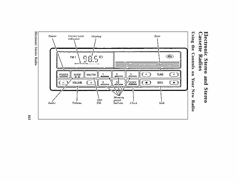
163
*[AS21300(BEF)05/95]
Electron
icS
tereoan
dS
tereoC
assetteR
adios
*[AS21400(BEF)02/95]
Usin
gth
eC
ontrols
onY
our
New
Rad
io
*[AS21415(BEF)04/95]
fullpageart:0060586-C
Electron
icS
tereoR
adio
File:ltasb.exU
pdate:Fri Jun 9 15:27:22 1995
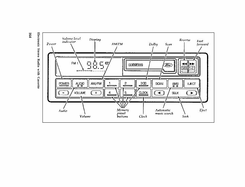
164
*[AS21420(BEF)04/95]
fullpageart:0060587-C
Electron
icS
tereoR
adio
with
Cassette
File:ltasb.exU
pdate:Fri Jun 9 15:27:22 1995

165
*[AS22305(BEF )05/95] How to tune radio stations (Stereo Radio)
*[AS22310(BEF )05/95] There are three ways for you to tune in to aparticular station. You can manually locate thestation by using the “TUNE” button, “SEEK” thestation or select the station by using the memorybuttons, which you can set to any desiredfrequency.
%*[AS22320(BEF )05/95] How to tune radio stations (Stereo CassetteRadio)
*[AS22350(BEF )02/95] There are four ways for you to tune in to aparticular station. You can manually locate thestation by using Automatic Music Search(“AMS”), “SEEK” the station, “SCAN” to thestation or select the station by using the memorybuttons, which you can set to any desiredfrequency.
*[AS22450(BEF )05/95] ❑Using the “TUNE” function
*[AS22460(BEF )05/95] You can change the frequency up or downone increment at a time by pressing andreleasing either the right (+) or left (-) side ofthe “TUNE” button. To change frequenciesquickly, press and hold down either the rightor left side of the “TUNE” button.
*[AS22470(BEF )04/95] Manual tuning adjusts your radio to anyallowable broadcast frequency, whether ornot a station is present on that frequency.(See All About Radio Frequencies in thissection.)
File:ltasb.exUpdate:Fri Jun 9 15:27:22 1995

166
*[AS22550(BEF )05/95] ❑Using the “AMS” function to manually tuneyour radio (Stereo Cassette Radio)
*[AS22650(BEF )02/95] You can change the frequency up or downone increment at a time by first pressing the“AMS” button (display shows “TUNE”) thenwithin approximately five seconds pressingand releasing either the right (a) or left (b)side of the “SEEK” button. To changefrequencies quickly, press and hold downeither the right or left side of the “SEEK”button.
*[AS22800(BEF )04/95] ❑Using the “SEEK” function
*[AS22900(BEF )04/95] This feature on your radio allows you toautomatically select listenable stations up ordown the frequency band. Press the right(a) side of the “SEEK” button to select thenext listenable station up the frequency band.Press the left (b) side of the button to selectthe next listenable station down thefrequency band. By holding the button down,listenable stations can be passed over to reachthe desired station.
*[AS23125(BEF )02/95] ❑Using the “SCAN” function (Stereo CassetteRadio)
*[AS23150(BEF )07/94] Press the “SCAN” button to enter the scanmode. The radio will begin scanning up thefrequency band, stopping on each listenablestation for approximately a five-secondsampling. This continues until you press the“SCAN” button a second time. The displayflashes “AM” or “FM.”
*[AS23200(BEF )04/95] ❑Setting the Station Memory Preset buttons
*[AS23250(BEF )05/95] Your radio is equipped with 5 stationmemory buttons. These buttons can be usedto select up to 5 preset AM stations and 10preset FM stations (5 in FM1 and 5 in FM2).
File:ltasb.exUpdate:Fri Jun 9 15:27:22 1995
167
*[AS23400(BEF )02/95] Follow the easy steps below to set these buttonsto the desired frequencies:
*[AS23500(BEF )04/95] 1. Select a band, then select a frequency.
*[AS23700(BEF )04/95] 2. Press one of the memory buttons and holdthe button until the sound returns. Thatstation is now held in memory on thatbutton.
*[AS23800(BEF )04/95] 3. Follow the two steps above for each stationmemory preset button you want to set.
*[AS23900(BEF )04/95] NOTE: If the vehicle’s battery is disconnected,the clock and station memory presetbuttons (if programmed in auto mode)will need to be reset.
*[AS24000(BEF )02/95] Adjusting the tone balance and speakeroutput of your radio
*[AS24150(BEF )05/95] Push the “AUDIO” button repeatedly untilthe display reads “BASS.” Push the right (+)side of the “VOLUME” button to increasebass (more “lows”), and push the left (-) sideto decrease bass (less “lows”).
*[AS24300(BEF )04/95] ❑ Increasing or decreasing treble response
*[AS24350(BEF )05/95] Push the “AUDIO” button repeatedly untilthe display reads “TREB.” Push the right (+)side of the “VOLUME” button to increase thetreble (more “highs”), and push the left (-)side to decrease treble (less “highs”).
File:ltasb.exUpdate:Fri Jun 9 15:27:22 1995

168
*[AS24500(BEF )08/89] Speaker features and operation
*[AS24600(BEF )04/95] ❑Adjusting speaker balance
*[AS24650(BEF )05/95] Balance control allows you to adjust thesound distribution between the right and leftspeakers. Push the “AUDIO” buttonrepeatedly until the display reads “BAL.”Push the right (+) side of the “VOLUME”button to shift the sound to the rightspeakers, and push the left (-) side to shiftthe sound to the left speakers.
*[AS24800(BEF )04/95] ❑Adjusting speaker fader
*[AS24850(BEF )05/95] Fade control allows you to adjust the sounddistribution between the front and rearspeakers. Push the “AUDIO” buttonrepeatedly until the display reads “FADE.”Push the right (+) side of the “VOLUME”button to shift the sound to the frontspeakers, and push the left (-) side to shiftthe sound to the rear speakers.
*[AS24950(BEF )05/94] NOTE: Illuminated bars show relative levels ofbass and treble and positions ofspeaker balance and fader functionsafter adjustments are made, then revertto volume level set.
*[AS25000(BEF )02/95] Using the Controls of Your Cassette TapePlayer
*[AS25500(BEF )02/95] How to insert a tape
*[AS25600(BEF )02/95] Insert a cassette (with the open edge to theright) firmly into the tape door opening, makingsure the cassette is completely in and “seated.”
*[AS25650(BEF )04/95] NOTE: A cassette tape can be loaded with theignition on whether or not the radiopower is on.
File:ltasb.exUpdate:Fri Jun 9 15:27:22 1995
169
*[AS25700(BEF )02/95] How to locate a desired track on the tape
*[AS26265(BEF )02/95] ❑Using the Automatic Music Search (“AMS”)
*[AS26270(BEF )03/95] Press and hold the “AMS” button (“AMS”will appear in the display). Then, push theleft (h) button to rewind to the beginningof the current selection or press the right(g) button to fast forward to the beginningof the next selection.
*[AS26900(BEF )02/95] ❑How to change the side of the tape beingplayed
*[AS27000(BEF )03/95] The alternate track (other side) of the tapecan be selected at any time by pushing bothfast-wind buttons (h and g) at thesame time.
*[AS27100(BEF )02/95] How to eject the tape
*[AS27250(BEF )02/95] To stop the tape and eject the cassette, press the“EJECT” button. The radio will resume playing.
*[AS27300(BEF )02/95] Using the DolbyH B noise reduction feature
*[AS27500(BEF )05/95] Push the k button to activate. Push again todeactivate.
*[AS27550(BEF )02/95] NOTE: Noise reduction system manufacturedunder license from Dolby LabsLicensing Corporation. “Dolby” anddouble-D symbol are trademarks ofDolby Laboratories LicensingCorporation.
*[AS27555(B )03/95] Clock Operation
*[AS27560(BEF )07/90] How to view the clock mode
*[AS27565(BEF )07/93] Press the “CLOCK” button to alternate thefrequency and time in the display. In the clockmode, pressing any radio function willautomatically display the radio frequency forapproximatedly ten seconds before changingback to the clock mode.
File:ltasb.exUpdate:Fri Jun 9 15:27:22 1995

170
*[AS27570(BEF )07/90] How to set the clock
*[AS27575(BEF )04/92] 1. Turn the radio on.
*[AS27585(BEF )03/95] 2. Press and hold in the “CLOCK” button,press the “SEEK” button left (b) to advancethe hours and right (a) to advance theminutes.
*[AS27595(BEF )07/90] NOTE: The clock displays 12-hour time withno AM/PM indications.
*[AS27600(BEF )02/95] Tips on Caring for the Cassette Player andTapes
*[AS27700(BEF )02/95] In order to keep your cassette tape playerperforming the way it was meant to, read andfollow these simple precautions:
*[AS27750(BEF )02/95] ❑Using a Ford Cassette Cleaning Cartridge toclean the tape player head after 10-12 hoursof play will help maintain the best playbacksound and proper tape operation.
*[AS27800(BEF )02/95] ❑Only cassettes that are 90 minutes long orless should be used. Tapes longer than 90minutes are thinner and subject to breakageor may jam the tape player mechanism.
*[AS27900(BEF )02/95] ❑Protect cassettes from exposure to directsunlight, high humidity and extreme heat orcold. If they are exposed to extremeconditions, allow them to reach a moderatetemperature before playing.
*[AS28001(BEF )02/95] ❑ If a tape is loose inside the cassette, tighten itbefore playing by putting your finger or apencil into one of the holes and turning thehub until the tape is tight.
*[AS28101(BEF )02/95] ❑Loose labels on cassette tapes can becomelodged in the mechanism. Remove any looselabel material before inserting a cassette.
File:ltasb.exUpdate:Fri Jun 9 15:27:22 1995
171
*[AS28200(BEF )03/95] ❑Do not leave a tape in the cassette tapeplayer when not in use. High heat in thevehicle can cause the cassette to warp.
%*[AS35200(BEF )02/95] Common Radio Reception Conditions
*[AS35300(BEF )02/95] Several conditions prevent FM reception frombeing completely clear and noise-free, such asthe following:
*[AS35400(BEF )04/95] 1. Distance/Strength
*[AS35500(BEF )02/95] The strength of the FM signal is directly relatedto the distance the signal must travel. Thelistenable range of an average FM signal isapproximately 25 miles (40 kilometers). Beyondthis distance, the radio is operating in a fringearea and the signal becomes weaker.
*[AS35600(BEF )04/95] 2. Terrain
*[AS35700(BEF )02/95] The terrain (hilly, mountainous, tall buildings) ofthe area over which the signal travels mayprevent the FM signal from being noise-free.
*[AS35900(BEF )01/95] If there is a building or large structure betweenthe antenna and station, some of the signal“bends” around the building, but certain spotsreceive almost no signal. Moving out of the“shadow” of the structure will allow the stationto return to normal.
*[AS36000(BEF )01/95] When the radio waves are reflected off objects orstructures, the reflected signal cancels the normalsignal, causing the antenna to pick up noise anddistortion. Cancellation effects are mostprominent in metropolitan areas, but also canbecome quite severe in hilly terrain anddepressed roadways.
File:ltasb.exUpdate:Fri Jun 9 15:27:22 1995

172
*[AS36100(BEF )01/95] To minimize these conditions, a stereo/monoblend circuit has been incorporated into thissystem. This feature automatically switches aweak stereo signal to a clearer monaural signal,which improves the quality of reception.
*[AS36200(BEF )01/95] Several sources of static are normal conditionson AM frequencies. These can be caused bypower lines, electric fences, traffic lights andthunderstorms.
*[AS36300(BEF )01/95] Another reception phenomenon is Strong SignalCapture and Overload. This can occur whenlistening to a weak station and when passinganother broadcast tower. The close station maycapture the more distant station, although thedisplayed frequency does not change. Whilepassing the tower, the station may switch backand forth a few times before returning to theoriginal station.
*[AS36400(BEF )01/95] When several broadcast towers are present(common in metropolitan areas) several stationsmay overload the receiver, resulting inconsiderable station changing, mixing anddistortion.
*[AS36500(BEF )01/95] Automatic gain control circuitry for both AMand FM bands has been incorporated into thissystem to reduce strong signal capture andoverload.
File:ltasb.exUpdate:Fri Jun 9 15:27:22 1995

173
%*[AS36600(BEF )08/89] All About Radio Frequencies
*[AS36700(BEF )05/95] The Federal Communications Commission (FCC)and the Canadian Radio TelecommunicationsCommission (CRTC) establish the frequenciesAM and FM radio stations may use for theirbroadcasts. The allowable frequencies are, AM:530, 540...1600, 1610 kHz in 10 kHz steps; FM:87.9, 88.1...107.7, 107.9 MHz in 0.2 MHz steps.
*[AS36800(BEF )01/95] Not all frequencies will be assigned to a givenarea. This radio will tune to each of thesefrequencies using MANUAL TUNE and no finetuning is necessary as radio stations may not useother frequencies.
*[AS36900(BEF )02/95] Some FM radio stations advertise a“rounded-off” frequency which is not thefrequency they actually broadcast on. Forexample, a radio station that is assigned afrequency of 98.7 MHz may call itself “Radio 99”even though 99.0 MHz is not an allowable FMbroadcast frequency.
File:ltasb.exUpdate:Fri Jun 9 15:27:22 1995

174
*[AS37000(BEF )01/95] Important Warranty and ServiceInformation
*[AS37050(BEF )07/90] Warranty
*[AS37100(BEF )03/95] Your sound system is warranted for three yearsor 36,000 miles (60,000 kilometers), whichevercomes first. Consult your vehicle warrantybooklet for further information. Ask your dealerfor a copy of this limited warranty.
*[AS37300(BEF )10/92] Service
*[AS37400(BEF )01/95] At Ford Electronics, we stand behind our audiosystems with a comprehensive service and repairprogram. If anything should go wrong withyour Ford audio system, return to your dealerfor service. There is a nationwide network ofqualified Ford authorized repair centers to assistyou.
File:ltasb.exUpdate:Fri Jun 9 15:27:22 1995

175
Driving Your Bronco
*[DR00350(BEF )03/95] Procedures for driving your vehicle will varydepending on which type of transmission yourvehicle has.
*[DR00550(BEF )04/95] ❑an Electronic 4-speed Automatic Transmission(E4OD)
*[DR00575(BEF )03/93] ❑an Electronic 4-speed Automatic Transmission(4R7OW)
*[DR00600(B F )03/95] ❑a manual transmission
*[DR00650(BEF )04/95] Your vehicle is equipped with an ElectronicPowertrain Control Module that limits engineand/or vehicle speeds with a cut-out mode topromote durability.
*[DR08650(BEF )03/93] Automatic TransmissionOperation (E4OD and 4R70W)
*[DR08710(BEF )03/94] The E4OD and 4R70W transmissions areelectronically controlled four speed automatictransmissions with overdrive. Transmissionoperation is controlled by the Powertrain ControlModule (PCM).
*[DR08720( ALL)08/94] The PCM will automatically adjust transmissionoperation to make up for varying conditions.Several sensors located on the engine andtransmission such as Throttle Position, EngineSpeed, Vehicle Speed and TransmissionTemperature are used by the PCM to shift thetransmission into a higher or lower gear whenrequired for the best performance and fueleconomy. For example, you may notice that thetransmission will upshift to a higher gear more
File:ltdrb.exUpdate:Fri Jun 9 15:26:57 1995

176
quickly when the vehicle is first driven and hasnot reached normal operating temperature.
*[DR08730( ALL)07/94] The PCM also controls the transmission’s TorqueConverter Clutch to further raise vehicleperformance and fuel economy. The TorqueConverter Clutch will engage when thetransmission operating temperature and otherconditions determined by the PCM have beenmet. Engagement of the clutch may be noted asa decrease in engine speed after an upshift hascompleted or when the driver has depressed thethrottle while driving at a steady road speed.
[DR08740( ALL)04/95] To help in troubleshooting, the PCM continuallyperforms self-tests on the electronic controlsystem and if any faults are detected, will storethem in memory. The Transmission ControlIndicator Light (TCIL), which is located on thegearshift lever, may flash steadily if amalfunction has been detected. If the TCIL isflashing, contact your Ford dealer as soon aspossible. If this condition persists, damage to thetransmission could occur.
[DR08745( ALL)04/95] NOTE: The word “OFF” located on the end ofthe gearshift lever is the transmissioncontrol indicator light (TCIL).
*[DR08750( ALL)01/95] Putting Your Vehicle in Gear
*[DR08800( ALL)03/94] Your vehicle’s gearshift is on the steeringcolumn. The Transmission Control Switch andindicator light are located on the end of thegearshift lever. You can put the gearshift in anyof the several positions.
File:ltdrb.exUpdate:Fri Jun 9 15:26:57 1995

177
*[DR08915(BEF )06/94]
one third page art:0021081-A
The positions of the column-mounted gearshift
*[DR08925( ALL)05/95]
quarter page art:0020771-C
Transmission Control Switch and indicator light (locatedon the gearshift lever)
*[DR09000( ALL)01/93] RWARNING
Hold the brake pedal down while youmove the gearshift lever from position toposition. If you do not hold the brakepedal down, your vehicle may moveunexpectedly and injure someone.
*[DR09100( ALL)01/95] Once you place the gearshift securely intoposition, gradually release the brake pedal anduse the accelerator as necessary.
File:ltdrb.exUpdate:Fri Jun 9 15:26:57 1995

178
*[DR09110( ALL)01/95] NOTE: Your vehicle is equipped with abrake-shift interlock feature. Thisfeature prevents you from shiftingfrom P (Park) unless you have thebrake pedal depressed. (The ignitionmust be in the ON position.) If youcannot shift from P (Park) with thebrake pedal depressed:
*[DR09120( ALL)01/95] 1. Apply the parking brake.
*[DR09130( ALL)01/95] 2. Remove the key.
*[DR09140( ALL)01/95] 3. Insert the key and rotate one positionclockwise (ignition in the OFF position).
*[DR09150( ALL)01/95] 4. Apply the brake pedal and shift to N(Neutral). (If the vehicle is shifted to P(Park), you must repeat the previous steps.)
*[DR09160( ALL)01/95] 5. Start the vehicle.
*[DR09165( ALL)05/95] If you need to shift out of P (Park) by using thealternate procedure described above, it ispossible that a fuse has blown and that yourbrakelamps may also not be functional. Pleaserefer to the chapter titled Servicing Your Broncoin this Owner Guide for instructions on checkingand replacing fuses.
*[DR09170( ALL)05/95] RWARNING
DO NOT DRIVE YOUR VEHICLE UNTILYOU VERIFY THAT THE BRAKELAMPSARE WORKING.
%*[DR09200( ALL)01/95] R (Reverse)
*[DR09300( ALL)02/95] With the gearshift in the R (Reverse) position,the vehicle will move backward. You shouldalways come to a complete stop before shiftinginto or out of R (Reverse).
File:ltdrb.exUpdate:Fri Jun 9 15:26:57 1995

179
%*[DR09400( ALL)01/95] Driving
%*[DR09500( ALL)04/95] When to use j (Overdrive)
*[DR09600( ALL)04/95] This is the normal driving position. As thevehicle picks up speed, automatic upshifts tosecond, third and fourth gears will occur whenj Overdrive is chosen on the selector and thetransmission control switch has not beenpressed. The transmission will shift into thecorrect gear when the right speed is achieved,for the accelerator pedal position you havechosen.
*[DR09700( ALL)03/94] When to use Drive
*[DR09800( ALL)05/95] You will note that there isn’t a drive position onyour gearshift indicator. However, you will finda Transmission Control Switch and an indicatorlight labeled “Overdrive” located on the end ofthe gearshift lever. Press this switch and theword “OFF” will illuminate on the shift leverknob. With the word “OFF” illuminated, thetransmission will operate in gears one throughthree. Operating in the Overdrive “OFF” modegives more engine braking than Overdrive andis useful for descending hills or when towing.
[DR09850( ALL)04/95]
quarter page art:0020771-C
Transmission Control Switch and indicator light (locatedon the gearshift lever)
File:ltdrb.exUpdate:Fri Jun 9 15:26:57 1995

180
*[DR09900( ALL)05/95] To return the transmission to the normal jOverdrive operation, press the transmissioncontrol switch again. The Transmission ControlIndicator Light will not be illuminated whenOverdrive operation resumes. This switch maybe used to select O/D ON or O/D OFF anytime the vehicle is being driven.
*[DR09950( ALL)05/94] When starting your vehicle, the overdrive systemwill automatically be in the normal overdrivemode.
*[DR10000( ALL)03/94] If the Transmission Control Indicator Light isflashing on and off steadily, a transmissionsystem malfunction was detected. Thetransmission will operate in a failuremanagement mode and may have harshengagements, firm shift feel, or abnormal shiftschedule. If this condition persists, damage tothe transmission could occur. Contact yourdealer as soon as possible.
*[DR10100( ALL)01/95] When to use 2 (Second)
*[DR10200( ALL)01/95] Use 2 (Second) to start-up on slippery roads orto provide additional engine braking ondowngrades. This position provides 2 (Second)gear operation only.
*[DR10300( ALL)01/95] When to use 1 (Low)
*[DR10400( ALL)04/95] Use 1 (Low) to provide maximum enginebraking on steep downgrades. Upshifts from 1(Low) can be made by manually shifting to 2(Second) or j (Overdrive). Selection of 1 (Low)gear provides only low gear operation fromstart-up. Selection of 1 (Low) while at higherspeeds provides a shift to second gear, and ashift to first gear will occur after the vehicledecelerates to the proper speed.
File:ltdrb.exUpdate:Fri Jun 9 15:26:57 1995

181
*[DR10500( ALL)01/95] P (Park)
*[DR10600( ALL)03/94] Always come to a complete stop before you shiftinto P (Park). This position locks thetransmission and prevents the rear wheels fromturning. To securely latch the gearshift in the P(Park) position, pull it toward you, push itcompletely counterclockwise against the stop,and then push it toward the instrument panel.
*[DR10650( ALL)03/94] The gearshift is securely latched in P (Park) ifyou cannot rotate it in a clockwise directionwithout lifting it toward you.
*[DR10700( ALL)05/95] RWARNING
Always set the parking brake fully andmake sure that the gearshift is securelylatched in P (Park).
[DR10725(B F )05/95] When the transfer case is in the N (Neutral)position, the engine and transmission aredisconnected from the rest of the driveline.Therefore, the vehicle is free to roll even if theautomatic transmission is in P (Park) or themanual transmission is in gear.
*[DR10750(B F )05/95] RWARNING
Do not leave the vehicle unattended withthe transfer case in the N (Neutral)position. Always set the parking brakefully and turn off the ignition whenleaving the vehicle.
*[DR10800( ALL)05/95] RWARNING
Never leave your vehicle unattendedwhile it is running.
File:ltdrb.exUpdate:Fri Jun 9 15:26:57 1995

182
*[DR11100( ALL)06/94] Forced Downshifts
*[DR11200( ALL)04/95] To gain extra acceleration in j Overdrive orDrive (O/D OFF), push the accelerator to thefloor. The transmission will automaticallydownshift to the appropriate gear: third, secondor first.
*[DR11235( ALL)03/94] Power Braking
*[DR11275( ALL)03/94] Increasing the engine speed above idle withoutvehicle movement (such as holding the brake) ina forward or reverse gear causes transmissionstall.
*[DR11285( ALL)03/94] NOTE: Continued operation in the stallcondition can result in transmissionoverheat, malfunction or fluidexpulsion.
*[DR11300(B F )03/95] Driving with a ManualTransmission
%*[DR11400(B F )03/95] Using the Clutch
*[DR11500(B F )01/95] Make sure the gearshift lever is in the N(Neutral) position and your right foot is holdingdown the brake pedal. Then press the clutchpedal to the floor with your left foot. Manualtransmission vehicles have a starter interlockswitch. The starter will not crank until the clutchpedal is fully depressed. Start the engine andallow it to idle for a few seconds. Move thegearshift into 1 (First) or R (Reverse).
*[DR11600(B F )03/91] To move the vehicle, release the clutch slowlyand at the same time press down slowly on theaccelerator so that the vehicle accelerates.
*[DR11700(B F )03/95] Do not drive with your foot resting on theclutch pedal and do not use the clutch to holdyour vehicle at a standstill while waiting on ahill. These actions will seriously reduce clutchlife.
File:ltdrb.exUpdate:Fri Jun 9 15:26:57 1995

183
*[DR11750(B F )03/95] Driving with your foot resting on the clutch maycause the vehicle to jerk sharply when pressingor removing your other foot from theaccelerator.
%*[DR11800(B F )03/95] Shifting the Gears
*[DR11900(B F )02/95] The gearshift for a manual transmission ismounted on the floor. The gearshift patternconsists of seven positions: Neutral, five forwardgears, and Reverse.
*[DR12000(B F )03/93]
quarter page art:0020134-A
5-Speed Overdrive manual transmission shift pattern
*[DR12300(B F )03/91] Backing up
*[DR12400(B F )03/95] To shift into R (Reverse):
*[DR12501(B F )03/91] 1. Push the clutch pedal in all the way to thefloor and hold it. If you do not hold theclutch pedal in all the way, you may hear agrinding noise when you shift.
*[DR12551(B F )03/93] 2. Bring your vehicle to a complete stop.Failure to do so may cause synchronizerteeth damage, reducing the useful life ofyour transmission.
*[DR12600(B F )08/94] 3. Put the gearshift in Neutral and wait at least3 seconds before shifting into R (Reverse) toprevent a grinding noise. Do not release theclutch.
*[DR12700(B F )08/94] 4. Push the gearshift all the way to the rightand pull it back into Reverse.
File:ltdrb.exUpdate:Fri Jun 9 15:26:57 1995

184
*[DR12800(B F )01/95] With the 5-speed transmission you can engage R(Reverse) only by moving the gearshift from theleft of 3 (Third) and 4 (Fourth) gears before youshift into R (Reverse). This is a special lockoutfeature that protects you from accidentallyshifting into R when you downshift from 5(Fifth) gear.
*[DR12950(B F )02/92] 5. Once R (Reverse) is engaged, slowly releasethe clutch pedal from the floor.
*[DR13000(B F )03/94] If R (Reverse) is not engaged, continue to pushthe clutch pedal in while you put the gearshiftback into Neutral. Then, release the clutch pedalfor a moment and repeat steps 2 through 5.
*[DR13100(B F )03/91] Upshifting/downshifting
*[DR13200(B F )03/91] Upshift and Downshift at the speeds that arespecified in the charts available for your engineand transmission.
File:ltdrb.exUpdate:Fri Jun 9 15:26:57 1995

185
*[DR13250(B F )03/91] Recommended Shift Speeds
[DR13550(B )06/93] 5.0L EFI Engine with 5-Speed ManualOverdrive Transmission
[DR13700(B )05/95]
twenty-eight pica chart:0020989-B
*[DR15100(B F )03/95] When you slow down or climb a steep hill,always downshift before the engine starts to losepower. Downshifting reduces the chance ofstalling and gives your vehicle better accelerationto increase speed again.
File:ltdrb.exUpdate:Fri Jun 9 15:26:57 1995

186
*[DR15200(B F )03/95] When you drive down steep hills, downshiftinghelps you keep a safe speed and helps preventunnecessary wear on the brakes.
*[DR15300(B F )03/95] When you come to a stop, do not downshiftthrough each gear. Disengage the clutch and usethe brake as necessary. Downshifting throughthe gears decreases your vehicle’s fuel economy.
*[DR15400(B F )05/95] RWARNING
Continued use of a damaged or wornclutch, prolonged clutch slippage ordownshifting at excessive speeds canresult in a failure of the engine,transmission or clutch components.
*[DR15500(B F )03/91] Transmission Function
*[DR15600(B F )03/91] Upshift at the speeds specified in the chartavailable for your engine and transmission. Allforward gears are synchronized allowing you toshift into them with your vehicle in motion. Theclutch pedal should be fully depressed whenshifting.
*[DR15625(B F )04/94] NOTE: Shifting during extremely low rpm’scan result in a momentary audiblerattle which disappears as vehiclerpm’s are increased. Shifting at higherspeeds will eliminate this sound.
*[DR15700(B F )03/95] Parking
*[DR15800(B F )01/95] To park your vehicle, apply the service brakepedal, and shift into N (Neutral) while stillmaintaining pressure on the service brake. Setthe parking brake fully. Shift into first and turnoff the ignition.
File:ltdrb.exUpdate:Fri Jun 9 15:26:57 1995
187
*[DR15900(B F )05/95] RWARNING
Do not park your vehicle in Neutral, itmay move unexpectedly and injuresomeone. Use 1 (First) gear and set theparking brake fully.
[DR15903(B F )05/95] When the transfer case is in the N (Neutral)position, the engine and transmission aredisconnected from the rest of the driveline.Therefore, the vehicle is free to roll even if theautomatic transmission is in P (Park) or themanual transmission is in gear.
*[DR15906(B F )05/95] RWARNING
Do not leave the vehicle unattended withthe transfer case in the N (Neutral)position. Always set the parking brakefully and turn off the ignition whenleaving the vehicle.
*[DR15915( ALL)01/95] Steering Your Vehicle%*[DR15945( ALL)01/95] Your vehicle comes with power steering. Power
steering uses energy from the engine to helpsteer your vehicle.
%*[DR15950( ALL)04/95] If the amount of effort needed to steer yourvehicle changes at a constant vehicle speed, havethe power steering system checked. If the powersteering system breaks down (or if the engine isturned off), you can steer the vehicle manuallybut it takes more effort.
*[DR15960( ALL)01/95] Never hold the steering wheel to the extremeright or left for more than five seconds if theengine is running. This can damage the powersteering pump.
File:ltdrb.exUpdate:Fri Jun 9 15:26:57 1995

188
*[DR15985( ALL)05/90] NOTE: After any severe impact such asstriking large potholes, sliding intocurbs on icy roads, or a collisioninvolving the front end, observe thesteering wheel alignment. If the spokesof the steering wheel seem to be in adifferent position while going straightdown the road, have the frontsuspension and steering checked forpossible damage.
*[DR16101(B F )03/95] Four-Wheel Drive (4WD)System (If equipped)
*[DR16130(B F )08/94] When you select the 4WD mode, your lighttruck uses all four wheels to power itself. Thisincreases traction, enabling you to drive your4x4 over terrain and road conditions two-wheeldrive vehicles cannot.
*[DR16160(B F )10/94] Power is supplied to all four wheels through atransfer case that allows you to select four-wheeldrive when necessary. Methods for engaging anddisengaging 4WD and low range will depend onwhich system your vehicle has.
File:ltdrb.exUpdate:Fri Jun 9 15:26:57 1995
189
*[DR16190(B F )01/95] 4x4 Systems — Lever Operated
*[DR16220(B F )06/94] The lever operated transfer case can be placedinto four positions. The 2H position is thetwo-wheel drive position in which power isdelivered only to the rear axle. The 4H positionprovides four-wheel drive with power deliveredto the front and rear axles for increased traction.The 4L position provides four-wheel drive withpower delivered to the front and rear axleswhen the above average power is required atreduced speeds. In the N (neutral) position, thereis no power delivered to either axle.
[DR16225(B F )05/95] When the transfer case is in the N (Neutral)position, the engine and transmission aredisconnected from the rest of the driveline.Therefore, the vehicle is free to roll even if theautomatic transmission is in P (Park) or themanual transmission is in gear.
*[DR16230(B F )05/95] RWARNING
Do not leave the vehicle unattended withthe transfer case in the N (Neutral)position. Always set the parking brakefully and turn off the ignition whenleaving the vehicle.
File:ltdrb.exUpdate:Fri Jun 9 15:26:57 1995

190
*[DR16250(B F )12/91]
two third page art:0020792-C
Transfer case selections
*[DR16310(B F )01/95] Four-wheel drive operation (4H or 4L) on drypavement is not recommended. Operating thevehicle in four-wheel drive on dry pavementwill increase tire wear, decrease fuel economy,and make four-wheel drive disengagementdifficult for the transfer case.
File:ltdrb.exUpdate:Fri Jun 9 15:26:57 1995

191
*[DR16370(B F )06/94] 4x4 system indicator lights
*[DR16401(B F )06/94] A 4x4 light and a LOW RANGE light arelocated at the lower right of the instrumentcluster.
*[DR16430(B F )06/94] ❑2H position — Neither the 4X4 or the LOWRANGE lights are lit.
*[DR16460(B F )06/94] ❑4H position — Only the 4x4 light is lit.
*[DR16490(B F )06/94] ❑N position — Neither the 4x4 or LOWRANGE lights are lit.
*[DR16520(B F )06/94] ❑4L position — Both the 4x4 and the LOWRANGE lights are lit.
*[DR16550(B F )03/91] Lever Operated System With AutomaticLocking Hubs
*[DR16580(B F )06/94] To shift from 2H to 4H:
*[DR16610(B F )02/92] Stop the vehicle and move the transfer case shiftlever straight back to the 4H position, theautomatic locking hubs will engage when thevehicle is driven. When the automatic lockinghubs are engaged, shifts between 2H and 4Hmay take place at any speed.
*[DR16620(B F )02/92] ❑The automatic locking hubs may disengage in2H if the vehicle’s direction is momentarilyreversed, or the vehicle is allowed to rollslightly in the opposite direction. If agrinding noise occurs when shifting from 2Hto 4H while the vehicle is moving, one orboth of the automatic locking hubs have beendisengaged and the transfer case shift levershould be switched back to the 2H position.To shift back into 4H, stop the vehicle andmove the transfer case shift lever straightback to the 4H position.
File:ltdrb.exUpdate:Fri Jun 9 15:26:57 1995

192
*[DR16630(B F )05/91] ❑When the vehicle is stopped while in 4H andthe vehicle’s direction is reversed from theprevious direction, the automatic locking hubsmomentarily disengage and then re-engage.The automatic locking hubs may click as theyautomatically engage in the new direction.
*[DR16640(B F )06/94] To shift from 4H to 2H:
*[DR16670(B F )03/93] Move the transfer case shift lever straightforward to the 2H position. This can be done atany speed. To disengage the automatic lockinghubs, operate the vehicle in 2H in the oppositedirection for approximately 10 feet (3 meters).
*[DR16701(B F )06/94] For example:
*[DR16730(B F )03/93] If you were driving the vehicle forward in4H, the automatic locking hubs willdisengage the next time the vehicle is drivenin reverse in 2H for approximately 10 feet (3meters).
*[DR16760(B F )03/93] If you were driving the vehicle in reverse in4H, the automatic locking hubs willdisengage the next time the vehicle is drivenforward in 2H for approximately 10 feet (3meters).
*[DR16790(B F )03/91] — Operating in 2H with the hubs lockedincreases fuel consumption, noise, vibration, andwear. For prolonged 2H operation on drypavement, disengage the automatic locking hubs.
File:ltdrb.exUpdate:Fri Jun 9 15:26:57 1995

193
*[DR16820(B F )06/94] To shift between 4H and 4L:
*[DR16851(B F )05/91] Stop the vehicle and place the automatictransmission into NEUTRAL or depress theclutch on manual transmission vehicles. Push thetransfer case shift knob down (toward theground) and at the same time pull or push thelever straight forward or rearward (dependingon the desired position, 4H or 4L) in order toshift the transfer case. This shift should be inone continuous motion without pausing in the N(neutral) position. Pausing in the neutral positioncan result in gear clash and difficult shifting. If,while shifting between 4H and 4L, the transfercase gets stuck in the N (neutral) position or isdifficult to shift into either 4H or 4L, it may benecessary to let the vehicle roll slightly and/orturn off the engine (particularly on vehiclesequipped with automatic transmissions).
*[DR16880(B F )03/91] To shift into and out of N (neutral)
[DR16940(B )03/91] To shift into N (neutral), stop the vehicle andengage the parking brake. Place the automatictransmission into NEUTRAL or depress theclutch. From either the 4H or 4L position, pushthe transfer case shift knob down (toward theground) and move the transfer case shift lever tothe N (neutral) position. The N (neutral) positionshould only be used for vehicle towing.
*[DR16955(B F )12/91] NOTE: Dash mounted four wheel driveindicator lights are off when yourvehicle is in neutral.
*[DR17001(B F )05/91] To shift from N (Neutral) to either 4H or 4L,stop the vehicle and engage the parking brake.Place the automatic transmission into NEUTRALor depress the clutch on manual transmissionvehicles. Push the transfer case knob down(toward the ground) and at the same time movethe transfer case shift lever to the desired
File:ltdrb.exUpdate:Fri Jun 9 15:26:57 1995

194
position. If it is difficult to shift into either 4H or4L, it may be necessary to let the vehicle rollslightly and/or turn off the engine (particularlyon vehicles equipped with automatictransmissions).
*[DR17030(B F )06/94] Lever Operated System With ManualLocking Hubs
*[DR17060(B F )06/94] To shift from 2H to 4H:
*[DR17090(B F )06/94] Stop the vehicle and engage the manual lockinghubs by turning both hub lock selector knobsclockwise to the LOCK position. Move thetransfer case shift lever straight back to the 4Hposition. After both hubs have been turned tothe LOCK position, shifts between 2H and 4H(or 4H to 2H) may take place at any speed.
*[DR17120(B F )03/91]
one third page art:0020146-C
Locking hub positions
*[DR17150(B F )06/94] ❑Do not drive the vehicle in 4H or 4L with themanual locking hubs in the FREE position.
*[DR17180(B F )06/94] ❑Do not drive the vehicle with the left andright manual locking hubs set to differentpositions.
*[DR17210(B F )06/94] To shift from 4H to 2H:
*[DR17240(B F )06/94] Move the transfer case shift lever forward to the2H position. This can be done at any speed.
File:ltdrb.exUpdate:Fri Jun 9 15:26:57 1995

195
However, the front driveline will remainengaged to the front wheels until the manuallocking hubs are disengaged. To disengage themanual locking hubs, stop the vehicle and rotateboth hub lock selector knobs counter-clockwiseto the FREE position.
*[DR17270(B F )06/94] Operating in 2H with the hubs in the LOCKposition increases fuel consumption, noise,vibration, and wear. For prolonged 2H operationon dry pavement, set the manual locking hubsto the FREE position.
*[DR17301(B F )06/94] To shift between 4H and 4L:
*[DR17330(B F )05/91] Stop the vehicle and place the automatictransmission into NEUTRAL or depress theclutch on manual transmission vehicles. Push thetransfer case shift knob down (toward theground) and at the same time pull or push thelever straight forward or rearward (dependingon the desired position 4H or 4L) in order toshift the transfer case. This shift should be withone continuous motion without pausing in the N(neutral) position. Pausing in the neutral positioncan result in gear clash and difficult shifting. If,while shifting between 4H and 4L, the transfercase gets stuck in the N (neutral) position or isdifficult to shift into either 4H or 4L, it may benecessary to let the vehicle roll slightly and/orturn off the engine (particularly on vehiclesequipped with automatic transmission).
*[DR17390(B F )06/94] To shift to N (neutral) from either 4H or 4L
[DR17480(B )05/91] To shift into N (neutral), stop the vehicle andengage the parking brake. Place the automatictransmission into NEUTRAL or depress theclutch on manual transmission vehicles. Fromeither the 4H or 4L position, push the transfercase shift knob down (toward the ground) andat the same time move the transfer case shift
File:ltdrb.exUpdate:Fri Jun 9 15:26:57 1995

196
lever to the N (neutral) position. The N (neutral)position should only be used for vehicle towing.
*[DR17490(B F )12/91] NOTE: Dash mounted four wheel driveindicator lights are off when yourvehicle is in neutral.
*[DR17540(B F )01/95] To shift from N (Neutral) to either 4H or 4L,stop the vehicle and engage the parking brake.Place the automatic transmission into N(Neutral) or depress the clutch on manualtransmission vehicles. Push the transfer case shiftlever to the desired position. If it is difficult toshift into either 4H or 4L, it may be necessary tolet the vehicle roll slightly and/or turn off theengine (particularly on vehicles equipped withautomatic transmissions).
*[DR17570(B F )06/94] 4x4 SYSTEMS-TOUCH DRIVE
*[DR17601(B F )06/94] The Touch Drive 4x4 system functions in threemodes. In Two Wheel Drive mode, power isdelivered only to the rear axle at normal roadspeed. The 4H position provides four-wheeldrive with power delivered to the front and rearaxles for increased traction. The 4L positionprovides four-wheel drive with power deliveredto the front and rear axles when the aboveaverage power is required at reduced speeds.
*[DR17630(B F )06/94] Four wheel drive operation (4x4 or 4x4 LOWRANGE) on dry pavement is not recommended.Operating the vehicle in four-wheel drive on drypavement will increase noise, vibration, tirewear, decrease fuel economy, and makefour-wheel drive disengagement difficult for thetransfer case.
File:ltdrb.exUpdate:Fri Jun 9 15:26:57 1995

197
*[DR17660(B F )06/94] Touch Drive system indicator lights
*[DR17690(B F )03/91] A 4x4 indicator light and a LOW RANGEindicator light are located at the lower right ofthe instrument cluster. In addition, two smallamber lights are located near the Touch Drivesystem buttons. The amber light to the left of the4x4 button will light up at the same time as the4x4 instrument panel light. The amber light tothe left of the LOW RANGE light will light upat the same time as the instrument panel LOWRANGE light.
*[DR17750(B F )06/94] ❑Two Wheel Drive mode — Neither the 4x4nor the LOW RANGE lights are lit.
*[DR17780(B F )06/94] ❑4x4 mode — Only the 4x4 light is lit.
*[DR17810(B F )06/94] ❑4x4 LOW RANGE mode — Both the 4x4 andLOW RANGE lights are lit.
*[DR17840(B F )06/94] To shift from Two-Wheel Drive to 4x4:
*[DR17871(B F )06/94] To shift into 4x4, push the 4x4 button located onthe instrument panel. This shift can be done at astop or at speeds up to 55 miles per hour(88 km/h). When the vehicle is driven, theautomatic locking hubs will engage. If thevehicle is stopped while in 4x4 and the vehicledirection is reversed from the previous direction,the automatic locking hubs will momentarilydisengage and reengage. The automatic lockinghubs may click as they automatically engage inthe new direction.
File:ltdrb.exUpdate:Fri Jun 9 15:26:57 1995
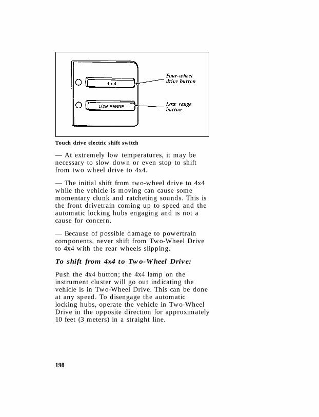
198
*[DR17900(B F )05/91]
one third page art:0020634-B
Touch drive electric shift switch
*[DR17945(B F )06/92] — At extremely low temperatures, it may benecessary to slow down or even stop to shiftfrom two wheel drive to 4x4.
*[DR17960(B F )06/94] — The initial shift from two-wheel drive to 4x4while the vehicle is moving can cause somemomentary clunk and ratcheting sounds. This isthe front drivetrain coming up to speed and theautomatic locking hubs engaging and is not acause for concern.
*[DR17990(B F )12/91] — Because of possible damage to powertraincomponents, never shift from Two-Wheel Driveto 4x4 with the rear wheels slipping.
*[DR18020(B F )06/94] To shift from 4x4 to Two-Wheel Drive:
*[DR18050(B F )06/94] Push the 4x4 button; the 4x4 lamp on theinstrument cluster will go out indicating thevehicle is in Two-Wheel Drive. This can be doneat any speed. To disengage the automaticlocking hubs, operate the vehicle in Two-WheelDrive in the opposite direction for approximately10 feet (3 meters) in a straight line.
File:ltdrb.exUpdate:Fri Jun 9 15:26:57 1995

199
*[DR18080(B F )06/94] For example:
*[DR18110(B F )06/94] If you were driving the vehicle forward in4x4, the automatic locking hubs willdisengage the next time the vehicle is drivenin reverse in Two-Wheel Drive forapproximately 10 feet (3 meters) in a straightline.
*[DR18140(B F )06/94] If you were driving the vehicle in reverse in4x4, the automatic locking hubs willdisengage the next time the vehicle is drivenforward in Two-Wheel Drive forapproximately 10 feet (3 meters) in a straightline.
*[DR18170(B F )01/95] Operating in two-wheel drive mode with thehubs locked increases fuel consumption, noise,vibration, and wear. For prolonged two-wheeldrive operation on dry pavement, disengagementof the automatic locking hubs, which is notrequired for two-wheel drive operation, stops allmovement of front-wheel drive componentswhile operating in two-wheel drive.
*[DR18230(B F )03/91] To shift from 4x4 to 4x4 LOW RANGE:
*[DR18290(B F )06/92] Stop the vehicle and place the automatictransmission in NEUTRAL or depress the clutchon vehicles with a manual transmission. Pushthe LOW RANGE button on the instrumentpanel to shift the transfer case from 4x4 to 4x4LOW RANGE. Both the 4x4 and LOW RANGElights are now lit.
*[DR18300(B F )08/94] NOTE: The vehicle must already be in 4x4before pushing the Low Range Button.
File:ltdrb.exUpdate:Fri Jun 9 15:26:57 1995

200
*[DR18320(B F )03/91] To shift from 4x4 LOW RANGE to 4x4:
*[DR18380(B F )06/94] Stop the vehicle and place the automatictransmission into NEUTRAL or depress theclutch on vehicles with a manual transmission.Push the LOW RANGE button on the instrumentpanel to shift the transfer case from 4x4 LOWRANGE to 4x4.
*[DR19200(B F )01/89] Driving Off Road with 4-WheelDrive
*[DR19300(B F )11/89] Most vehicles with four-wheel drive areespecially equipped for driving on sand, snow,mud, or rough terrain and have operatingcharacteristics that are somewhat different fromconventional vehicles, both off and on the road.The driving tips below will help you learn touse four-wheel drive.
*[DR19400(B F )10/94] ❑Do not use 4WD LOW on dry, hard-surfacedroads.
*[DR19600(B F )11/89] ❑Special maintenance procedures are necessaryafter operating with drive components inwater.
*[DR19700(B F )08/94] ❑Manual locking hubs must be in LOCKposition before shifting into four-wheel drive.
*[DR19800(B F )11/89] When using four-wheel drive, maintain steeringwheel control at all times, especially in roughterrain. Since sudden changes in terrain canresult in abrupt steering wheel motion, makesure you grip the steering wheel rim from theoutside. Do not grip the spokes.
*[DR19900(B F )05/90] Drive cautiously to avoid vehicle damage fromconcealed objects such as rocks and stumps.Know the terrain or examine maps of the area inquestion before driving. Map out your routebeforehand. To maintain steering and brakingcontrol of your vehicle, you must have all four
File:ltdrb.exUpdate:Fri Jun 9 15:26:57 1995

201
tires on the ground, and they must be rolling,not sliding or spinning.
*[DR19925(B F )11/89] Transmission upshift in 4x4 with transfer case in4L may be quite firm due to large total gearreduction. This condition is normal.
*[DR20000(B F )11/89] Sand
*[DR20100(B F )11/89] When driving over sand, try to keep all fourwheels of the vehicle on the most solid area ofthe trail. Do not reduce the tire pressures butshift to a lower gear and drive steadily throughthe terrain. Apply accelerator slowly and avoidspinning the wheels.
*[DR20200(B F )11/89] Mud and Water
*[DR20300(B F )12/89] When driving through water, determine thedepth; avoid water higher than the bottom ofthe hubs (if possible) and proceed slowly. If theignition system gets wet, the vehicle may stall.
*[DR20400(B F )11/89] Once through water, always try the brakes. Wetbrakes do not stop the vehicle as effectively asdry brakes. Drying can be improved by movingyour vehicle slowly, while applying lightpressure on the brake pedal.
*[DR20500(B F )11/89] After driving through mud, clean off residuestuck to rotating driveshafts and tires. Excessmud stuck on tires and rotating driveshaftscauses an imbalance which could damage drivecomponents.
*[DR20525(B F )07/94] NOTE: If the transmission and transfer case issubmerged in water, their fluids shouldbe checked and changed, if necessary.
File:ltdrb.exUpdate:Fri Jun 9 15:26:57 1995

202
*[DR20650(B )11/89] Additional Special DrivingInstructions for Utility Vehicles
*[DR20701(B F )11/89] Driving on Hill or Slope Terrain
*[DR20800(B F )08/94] When driving on a hill, it may be necessary totravel diagonally up or down. Avoid drivingcrosswise or turning on steep slopes, you couldlose traction and slip sideways. Drive straightup, straight down or avoid the hill completely.Know the conditions on the other side of a hillbefore driving over the crest.
*[DR20900(B F )11/89] When climbing a steep hill, start in a lower gear,rather than finding it necessary to downshiftfrom a higher gear after the ascent has started.This reduces strain on the engine and thepossibility of stalling.
*[DR21000(B F )11/89] When descending a steep hill avoid suddenbraking. Rapid pumping of the brake pedal willhelp slow the vehicle and still maintain steeringcontrol.
*[DR21101(B F )11/89] Driving on Snow or Ice
*[DR21200(B F )10/90] A four-wheel drive vehicle has advantages overtwo-wheel drive vehicles in snow and ice butcan skid like any other vehicle. If so equipped,keep the vehicle in four-wheel drive if icy orslippery conditions exist.
*[DR21300(B F )11/89] Avoid sudden applications of power and quickchanges of direction on snow or ice. Apply theaccelerator slowly and steadily when startingfrom a full stop.
[DR21312(B F )05/95] All utility-type and Four-Wheel Drive vehicleshave special design and equipment features tomake them capable of performing in a widevariety of off-road applications. Specific designcharacteristics give them higher centers ofgravity than ordinary passenger cars.
File:ltdrb.exUpdate:Fri Jun 9 15:26:57 1995

203
*[DR21325(B F )05/95] RWARNING
All utility and four-wheel drive vehiclesare not designed for cornering at speedsas high as passenger cars any more thanlow-slung sports cars are designed toperform satisfactorily under off-roadconditions. Avoid sharp turns or abruptmaneuvers in these vehicles.
%*[DR21400( ALL)03/95] Brakes
*[DR21500( ALL)01/93] Front Disc Brakes
*[DR21600( ALL)03/94] The front disc brakes are self-adjusting. They donot require service other than periodic inspectionfor pad wear.
*[DR21900(BEF )10/94] Rear Drum Brakes
*[DR22000(BEF )03/95] The rear drum brakes are self-adjusting.Automatic adjustment occurs when the brakesare applied while “backing up.” If normaloperation does not include much backing, adjustthe brakes when they seem “low,” using theprocedure under If Brakes Do Not Grip Well orPedal is Low in this chapter.
*[DR22100( ALL)11/89] Hydraulic Power Brakes
*[DR22200(BEF )08/94] The hydraulic brake system is made up of twoindependent hydraulic circuits. One hydrauliccircuit supplies fluid to the front disc brakes andthe other hydraulic circuit supplies fluid to therear drum brakes. These two circuits aresupplied by a common hydraulic brake fluidreservoir, with a fluid level sensor.
*[DR22300( ALL)11/89] The brake light in the instrument cluster willlight for low brake fluid in the common brakefluid reservoir.
File:ltdrb.exUpdate:Fri Jun 9 15:26:57 1995

204
*[DR22400( ALL)05/95] RWARNING
An increase in pedal travel will result inreduced braking capability. The brakesystem should be checked immediately.
[DR22905(B )08/94] Anti-lock Brake System
*[DR22910(B )08/94] Your vehicle is equipped with a Four WheelAnti-lock Braking System (4WABS). The 4WABShelps the driver to maintain vehicle control bypreventing wheel lockup during hard braking.
*[DR22915(BE )03/94] The 4WABS operates with a computer that isable to optimize vehicle control during brakingon varying tire and road conditions bymodulating the brake pressure at each of thefront wheels and the rear axle. This “pumpingaction” is similar to the driver “pumping” thebrakes but happens at a much faster rate.
*[DR22920(BE )05/95] RWARNING
The Anti-lock system does NOT assist thevehicle in stopping quickly on wet or icysurfaces. Heavy braking combined withpoor road conditions could cause you tolose steering control of your vehicle.
*[DR22925(BE )10/94] Using anti-lock brakes
*[DR22930(BE )05/94] The operation of a vehicle with 4WABS is notsimilar to the operation of normal brakes. Somedifferences exist and are listed below:
*[DR22935(BE )10/94] ❑Apply the brake steadily. In the event of apanic stop, do NOT “pump” the brakes.“Pumping” the brakes during an Anti-lockstop will diminish braking effectiveness.
File:ltdrb.exUpdate:Fri Jun 9 15:26:57 1995

205
*[DR22940(BE )10/94] ❑During an Anti-lock stop, the driver willnotice a brake pedal pulsation and hear somenoise from the engine compartment. This isan indication that the 4WABS system isworking correctly and is normal.
*[DR22945(BE )05/95] RWARNING
The Anti-lock system does NOT decreasethe time necessary to apply the brakes.Always leave enough room between thevehicle in front of you and your vehicle.
*[DR22950(BE )05/95] 4WABS driver warning light
[DR22955(BE )08/94] The 4WABS computer continuously monitors thesystem while driving for any electrical faults orsystem malfunctions. In addition, the 4WABScomputer performs an initial system check calledbulb proveout when the vehicle ignition isswitched on. During bulb proveout, the amber“ABS” light on the instrument cluster willmomentarily illuminate and then go out.
*[DR22960(BE )03/93] NOTE: After starting the vehicle and uponinitial drive-off, the driver may noticea single pulse of the brake pedal and anoise from the engine compartment.This is part of the initial system checkand is normal.
[DR22965(BE )08/94] Should a malfunction in the 4WABS systemoccur, the amber “ABS” light on the instrumentcluster will come on and stay on indicating thatthe antilock system has been shut down and thevehicle needs to be serviced. Normal braking isnot affected unless the red brake warning lightis also illuminated.
File:ltdrb.exUpdate:Fri Jun 9 15:26:57 1995

206
*[DR22970(BE )10/94] NOTE: It is important to note that when theABS Warning Light is illuminated theABS system is disabled. The vehiclemust be serviced immediately torestore the benefits of the Anti-locksystem.
*[DR22975(BE )10/94] NOTE: Mobile phones or radio transmittersnot installed by Ford Motor Companymay interfere with the Anti-lockSystem. Should the Anti-lock systemactivate unexpectedly or the Anti-lockWarning Light illuminate afterinstallation of such a unit, have theinstallation of the unit checked.
*[DR23000(BE M)12/89] If Brakes Do Not Grip Well or Pedal is“Low”
*[DR23200(BEF )11/89] If brakes do not grip well, it may indicate therear drum brakes need adjustment. To do this,drive the vehicle in reverse at 5 mph (8 km/h)on level, dry pavement. Stop the vehicle byfirmly applying the brakes. Repeat thisprocedure four or five times.
*[DR23250( ALL)11/89] If during normal operation the brake pedalseems “low”, it may indicate the need for abrake system inspection and/or service. Youshould have your brakes checked as soon aspossible.
*[DR23300( ALL)02/95] Occasional brake squeal during light to moderatestops does not affect the function of the brakesystem and is normal. However, if the squealbecomes annoyingly loud or increasessignificantly in frequency of occurrence, returnthe vehicle to your dealer for inspection.
File:ltdrb.exUpdate:Fri Jun 9 15:26:57 1995

207
*[DR23400(BEF )11/89] RWARNING
Modifications to the suspension springrates and/or vehicle ride height mayadversely affect vehicle stopping ability.
*[DR23500(BEF )07/92] If Brakes Pull
*[DR23600(BEF )07/92] ❑Check tire pressure
*[DR23700(BEF )07/92] ❑Perform the self-adjustment proceduredescribed under If Brakes Do Not Grip Well orPedal is “Low.”
*[DR23800(BEF )05/95] If pull occurs during the first 500 miles(800 km), make 10 moderately fast stops from40 mph (65 km/h) and then perform theself-adjustment procedure above. It may benecessary to repeat this operation to properlyseat new brake linings and pads.
*[DR24000( ALL)01/93] Stopping Distances
*[DR24100( ALL)11/89] Stopping distances vary with different loads anddriving conditions. Use caution whenencountering new conditions and acquaintyourself with vehicle performance. Take fulladvantage of engine braking power whenslowing down.
%*[DR24200( ALL)01/95] Applying the Brakes
*[DR24300( ALL)05/95] Apply the brake pedal gradually. Use the“squeeze” technique — push on the brake pedalwith a steadily increasing force. This allows thewheels to continue to roll while you are slowingdown, which lets you steer properly.
*[DR24400( ALL)05/95] RWARNING
Do not drive with your foot resting on thebrake pedal. This will increase yourvehicle’s stopping distance and may alsocause brake damage.
File:ltdrb.exUpdate:Fri Jun 9 15:26:57 1995

208
*[DR24500( ALL)05/95] RWARNING
If you are driving down a long or steephill, shift to a lower gear. Do not applyyour brakes continuously, as they mayoverheat and become less effective.
*[DR24600( ALL)03/95] Using the Parking Brake
*[DR24650(BEF )01/95] The parking brake should be used whenever youpark your vehicle.
*[DR24800(B F )12/91] The parking brake pedal is suspended just belowthe bottom of the instrument panel to the left ofservice brake and/or clutch pedals. To set theparking brake while parking your vehicle, pressthe brake pedal with your right foot and hold itwhile you push the parking brake pedal downfirmly and fully with your left foot.
*[DR24920(B FM)07/91]
one third page art:0020893-A
Parking Brake
File:ltdrb.exUpdate:Fri Jun 9 15:26:57 1995
209
*[DR24950(B F )03/95] RWARNING
When parking, do not use the gearshift inplace of the parking brake. Turn the keyto LOCK whenever you leave yourvehicle. Always set the parking brakefully and make sure that the gearshift issecurely latched in P (Park) (automatictransmission) or in 1 (First) (manualtransmission). Never leave your vehicleunattended while it is running. If you donot take these precautions, your vehiclemay move unexpectedly and injuresomeone.
[DR24970(B F )05/95] When the transfer case is in the N (Neutral)position, the engine and transmission aredisconnected from the rest of the driveline.Therefore, the vehicle is free to roll even if theautomatic transmission is in P (Park) or themanual transmission is in gear.
*[DR24975(B F )05/95] RWARNING
Do not leave the vehicle unattended withthe transfer case in the N (Neutral)position. Always set the parking brakefully and turn off the ignition whenleaving the vehicle.
*[DR25000(B FM)03/93] To release the parking brake, press the servicebrake pedal with your right foot and pull theparking brake release lever.
*[DR25050( ALL)01/93] RWARNING
If the parking brake is fully released, butthe Brake System light remains on, havethe brakes checked immediately. Theymay not be working properly.
File:ltdrb.exUpdate:Fri Jun 9 15:26:57 1995

210
*[DR25100( ALL)01/95] The parking brake is not designed to stop amoving vehicle, but you can use the parkingbrake to stop your vehicle in an emergency ifthe normal brakes fail. However, since theparking brake applies only the rear brakes, thestopping distance will increase greatly and thehandling of your vehicle will be adverselyaffected.
*[DR25200( ALL)01/95] Driving Under Special Conditions
*[DR25250( ALL)01/95] Tips for Safe Driving
*[DR25301( ALL)05/95] As with any new vehicle, yours may drive andhandle differently from your previous vehicle.Use care until you become accustomed to itsvarious features and driving characteristics.
*[DR25350( ALL)03/95] Operate your vehicle within reasonable limits.Sudden acceleration, deceleration, turning, orcombinations of these maneuvers can cause avehicle to behave differently than anticipated.
*[DR25501( ALL)02/95] Wheel Spin
*[DR25550( ALL)11/92] ❑Extreme acceleration can cause the rearwheels to spin, perhaps resulting in reducedsteering control.
*[DR25601( ALL)05/90] If the wheels spin during vehicle start-up, shiftto a different gear:
*[DR25750(B F )03/93] ❑Automatic Overdrive 4R7OW: use 2 (Second)
*[DR25800( ALL)03/93] ❑Electronic 4-Speed Automatic TransmissionE4OD: use 2 (Second)
*[DR25950(B F )05/90] ❑Mazda R2 5-Speed Overdrive Manual: use 2(Second)
*[DR26301( ALL)01/89] Move forward slowly and evenly. If this doesnot work, try rocking the vehicle.
*[DR26401(B F )05/91] For 4x4 vehicles, engage 4WD, and try to driveaway.
File:ltdrb.exUpdate:Fri Jun 9 15:26:57 1995

211
*[DR26550( ALL)05/90] High Speed Driving
*[DR26575( ALL)05/95] Ford Motor Company recommends obeyingposted speed limits.
*[DR26601( ALL)05/95] RWARNING
Driving too fast for conditions creates thepossibility of loss of vehicle control.Driving at very high speeds for extendedperiods of time may result in damage tovehicle components.
*[DR26625(BEF )12/91] Speed limiter
*[DR26652(BEF )03/94] All models are equipped with an electronicengine control system (EEC) which limits themaximum engine speed and thus road speed intop gear. Vehicle operation is normal since thecontrolled maximum speed is above postedhighway speeds in North America.
%*[DR26701( ALL)01/95] Driving in Bad Weather
%*[DR26750( ALL)01/95] Slippery roads
*[DR26801( ALL)03/95] Drive cautiously on wet or snowy roads:
*[DR26850( ALL)03/95] ❑Do not quickly move the steering wheelunless necessary.
*[DR26901( ALL)01/95] ❑Drive slower than you normally would.
*[DR26951( ALL)01/95] ❑Give your vehicle more distance to stop.
*[DR27025( ALL)07/94] ❑To stop on ice, shift to Neutral below 10 mph(16 km/h) and gently pump brakes. (Exceptwith 4WAL)
*[DR27050( ALL)02/93] ❑Consider using one of the lower gears.
*[DR27101(B F )05/91] ❑For 4x4 vehicles, engage 4WD, and try todrive slowly away.
File:ltdrb.exUpdate:Fri Jun 9 15:26:57 1995

212
*[DR27150(B F )05/95] RWARNING
To avoid losing control on slippery roads,do not downshift into Low with theautomatic transmission when movingfaster than 20 mph (32 km/h). Do notdownshift into First with the manualtransmission when moving faster than5 mph (8 km/h).
*[DR27350(B F )06/94] RWARNING
The rear antilock brake system may notprevent brake lock-up on extremelyslippery surfaces. Rear brake lock-up mayalso occur while driving in four-wheeldrive because the transfer case couples thefront and rear axles together.
*[DR27450(BEF )03/95] Traction-Lok Rear Axle (If equipped)
*[DR27501(BEF )03/95] This axle provides added drive away traction onslippery surfaces, particularly when one or morewheels are on a surface with poor traction.
*[DR27550(BEF )03/93] Extended use of other than matching size tireson a Traction-Lok rear axle could result in apermanent reduction in effectiveness. This loss ofeffectiveness does not affect normal driving andshould not be noticeable to the driver.
*[DR27601(BEF )05/95] RWARNING
To avoid injury, never run the enginewith one wheel off the ground, such aswhen changing a tire.
File:ltdrb.exUpdate:Fri Jun 9 15:26:57 1995

213
%*[DR27651( ALL)01/95] High water
*[DR27675( ALL)06/92] Never attempt to cross water that is fast flowingor of unknown depth.
*[DR27701( ALL)05/90] Do not drive through flooded areas unless youare sure that the water is below the bottom ofthe wheel hubs.
*[DR27750( ALL)04/94] If you must drive through high water, driveslowly. You may have limited traction or wetbrakes, so allow extra stopping distance becauseyour vehicle will not stop as quickly as usual.
*[DR27801( ALL)01/95] After you drive through the standing water,apply your brakes gently several times as yourvehicle moves slowly. This helps to dry thebrakes.
*[DR27820( ALL)07/94] NOTE: If the transmission and transfer case issubmerged in water, their fluids shouldbe checked and changed, if necessary.
*[DR27825( ALL)03/93] NOTE: All rear axle lube quantities must bereplaced every 100,000 miles(160,000 km) or if the axle has beensubmerged in water. Otherwise, thelube should not be checked or changedunless a leak is suspected or repairrequired.
*[DR27850( ALL)11/89] Rocking the vehicle
*[DR27901(B F )05/90] For 4x4 vehicles, engage 4WD LOW, when thevehicle gets stuck and try to drive away.
*[DR27950( ALL)05/95] If your vehicle gets stuck (for example, in mudor snow), you may rock it out of the spot. Shiftin a steady rhythm between forward and reversegears. Allow the transmission to fully engage,then press lightly on the accelerator. Do not rockthe vehicle for more than a few minutes. This
File:ltdrb.exUpdate:Fri Jun 9 15:26:57 1995

214
may overheat the engine and transmission,causing damage to both. In addition, othervehicle systems and components may also bedamaged.
*[DR27975( ALL)05/95] RWARNING
Do not spin the wheels at over 35 mph(56 km/h). The tires may fail and injure apassenger or bystander.
*[DR28050(BEF )03/95] Driving With a Heavy Load
*[DR28101(BEF )01/95] There are limits to the amount of weight yourvehicle can carry or tow. The total weight ofyour vehicle, plus the weight of the passengersand cargo, should never be more than the GrossVehicle Weight Rating (GVWR). Also, the weightthat your vehicle carries over the front axle andrear axle should never be more than the GrossAxle Weight Rating (GAWR) for the respectiveaxle.
*[DR28150(BEF )01/95] The weight limits of your vehicle’s tires affectthe GVWR or GAWR limitations. Usage ofreplacement tires with higher weight limit thanoriginals does not increase GVWR or GAWR.Usage of lower capacity replacement tires maylower GVWR and GAWR limitations.
*[DR28201(BEF )02/95] RWARNING
If the GVWR or the GAWR specified onthe Safety Compliance Certification Labelis exceeded, your vehicle may be damagedor you may lose control and injuresomeone.
File:ltdrb.exUpdate:Fri Jun 9 15:26:57 1995

215
*[DR28250(B F )03/91] Heavy duty front suspension package(option)
*[DR28301(B F )03/91] This optional front suspension package isdesigned to handle the additional loads that willbe imposed on the vehicle by adding aftermarketequipment, such as a snowplow. Refer to theSafety Compliance Certification Label for details.
*[DR28750( ALL)01/93] Vehicle/Trailer Loads
*[DR28801( ALL)06/92] All vehicles may tow a Class I trailer providedthe Gross Combined Weight (GCW) is less thanor equal to the GVWR shown on the SafetyCompliance Certification Label. For heaviertrailer applications, refer to the towinginformation found later in this chapter.
*[DR28950(BEF )02/95] Trailer Towing (may require trailer towoption package)
*[DR29001( ALL)03/91] Towing a trailer puts additional loads on yourvehicle’s engine, transmission, axle, brakes, tiresand suspension. For your safety and for thegood of your vehicle, use the right equipmentfor the type of trailer you tow.
[DR29010(B F )05/95] If your trailer is equipped with electric brakes,auxiliary battery, or back-up lamps, the optional7 wire trailer towing electrical hook-up will berequired on the vehicle.
*[DR29025( ALL)09/92] Your trailer towing capability will vary based onthe standard and optional equipment on yourvehicle. Refer to the following VehicleLoading/Towing Information and the TrailerTowing Tables to determine the specific towingcapability of your vehicle.
*[DR29050( ALL)02/92] ❑Stay within the load limits when you tow.
File:ltdrb.exUpdate:Fri Jun 9 15:26:57 1995

216
*[DR29101( ALL)01/95] ❑Carefully and thoroughly prepare yourvehicle for towing, making sure to use theright equipment and to attach it properly.(See Preparing to Tow in this chapter.)
*[DR29151( ALL)01/95] ❑Use extra caution when driving your vehiclewhile you tow. (See Driving while you tow inthis chapter.)
*[DR29201( ALL)01/95] ❑Service your vehicle more frequently if youtow a trailer. (See Servicing your vehicle if youtow in this chapter.)
*[DR29350( ALL)05/94] Do not tow a trailer until your vehicle has beendriven at least 500 miles (800 km).
*[DR29401( ALL)06/92] Vehicle Loading/TowingInformation
*[DR29450(BEF )03/91] Your vehicle’s load capacity is designated byweight, not volume, so you cannot necessarilyuse all available space with large or heavy loads.Maximum safe vehicle weights as well as tire,rim sizes and inflation pressures are specified foryour vehicle at the assembly plant on the SafetyCompliance Certification Label. The CertificationLabel is located on the left front door lock facingor the door latch post pillar.
*[DR29501( ALL)12/91] Trucks, unlike passenger cars, are basicallycustom vehicles designed to carry a load. Mostowners start with a base vehicle and addproduction and dealer installed and/oraftermarket components to suit their tastes andpurposes. Even trucks that are purchased forpersonal transportation only are likely to haveconsiderable optional equipment, such as stepbumpers and light bars, for example.
File:ltdrb.exUpdate:Fri Jun 9 15:26:57 1995
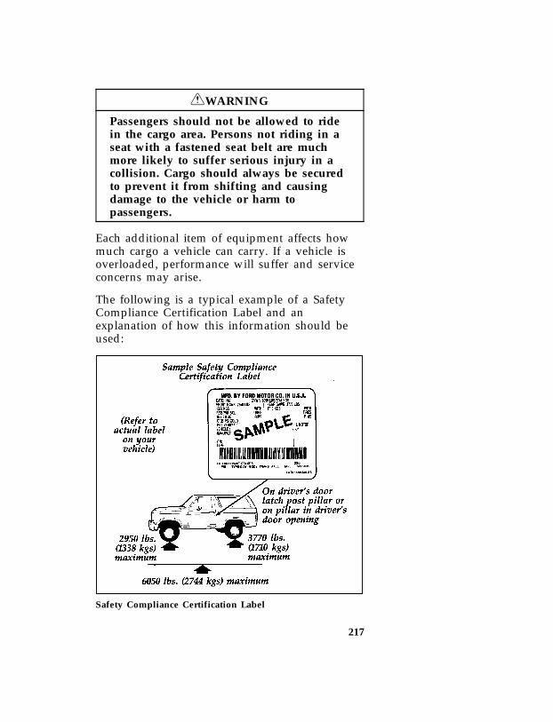
217
*[DR29525( ALL)05/95] RWARNING
Passengers should not be allowed to ridein the cargo area. Persons not riding in aseat with a fastened seat belt are muchmore likely to suffer serious injury in acollision. Cargo should always be securedto prevent it from shifting and causingdamage to the vehicle or harm topassengers.
*[DR29551( ALL)03/91] Each additional item of equipment affects howmuch cargo a vehicle can carry. If a vehicle isoverloaded, performance will suffer and serviceconcerns may arise.
*[DR29601(BEF )04/95] The following is a typical example of a SafetyCompliance Certification Label and anexplanation of how this information should beused:
[DR29701(B )05/89]
half page art:0020149-C
Safety Compliance Certification Label
File:ltdrb.exUpdate:Fri Jun 9 15:26:57 1995

218
*[DR29950(BEF )06/92] Do not use the sample numbers on the SafetyCompliance Certification Label shown. Use theactual numbers from your vehicle certificationlabel.
*[DR30001( ALL)06/92] Understanding Loading/TowingInformation
*[DR30050( ALL)03/94] The following terms are used to describe theability to carry or tow a load:
*[DR30101( ALL)01/93] ❑Base Curb Weight
*[DR30150( ALL)01/93] ❑Payload
*[DR30200( ALL)01/93] ❑GVW (Gross Vehicle Weight)
*[DR30250( ALL)01/93] ❑GVWR (Gross Vehicle Weight Rating)
*[DR30301( ALL)01/93] ❑GAWR (Gross Axle Weight Rating)
*[DR30310( ALL)06/92] ❑GCWR (Gross Combined Weight Rating)
*[DR30320( ALL)06/92] ❑Maximum Trailer Weight Rating
*[DR30330( ALL)06/92] ❑Maximum Trailer Weight
*[DR30340( ALL)06/92] ❑Trailer Weight Range
*[DR30351( ALL)03/91] Base Curb Weight
*[DR30401( ALL)03/94] The Base Curb Weight is the weight of thevehicle including fuel, coolants, lubricants,emergency tools, spare wheel and tire. It alsoincludes any equipment that is standard on thatmodel. It does not include passengers, cargo oroptional equipment installed by factory, dealer,aftermarket supplier or customer.
*[DR30451( ALL)03/91] Payload
*[DR30501( ALL)03/91] Payload is the combined, maximum allowableweight of cargo, occupants and optionalequipment that the truck is designed to carry. Itis Gross Vehicle Weight Rating minus the basecurb weight.
File:ltdrb.exUpdate:Fri Jun 9 15:26:57 1995

219
*[DR30550( ALL)03/91] Gross Vehicle Weight (GVW)
*[DR30601( ALL)03/91] If you add base curb weight and the weight of aload (including passengers, cargo and optionalequipment) being carried at a particular time,you get the Gross Vehicle Weight (GVW).
*[DR30650( ALL)10/94] It is important to remember that GVW is not alimit or a specification. If an owner loads up avehicle and weighs it, that’s the GVW at thatmoment. If the owner piles on more of a loadand weighs it again, that becomes theGVW...until such time as the vehicle is unloaded.
*[DR30701( ALL)03/91] Gross Vehicle Weight Rating (GVWR)
*[DR30750( ALL)10/94] To avoid overloading a vehicle, the ownershould observe the manufacturer’s specifiedGross Vehicle Weight Rating. The GVWR is themaximum total weight of base vehicle,passengers, optional components and cargo thata particular vehicle was designed to carry.
*[DR30801( ALL)01/93] Gross Axle Weight Rating (GAWR)
*[DR30850( ALL)03/91] We have all seen a car or a truck that is loadeddown in the rear and riding high in the front.This is a dangerous condition that usually meansthat the rear suspension components are undersevere strain and that vehicle handling isimpaired. There is more to carrying a load thanjust payload or GVWR.
*[DR30901( ALL)03/91] Your Safety Compliance Certification Label notonly gives the GVWR, it also gives the GrossAxle Weight Rating (GAWR) which is thecarrying capacity for each axle system. Fortrucks, the rear axle will be designed to carrymore weight than the front.
*[DR30950( ALL)06/92] The rating is based on the carrying capacity ofthe lowest rated axle and suspension componentas well as other factors. This is why it’s soimportant to observe vehicle loading ratings.
File:ltdrb.exUpdate:Fri Jun 9 15:26:57 1995

220
Overloading a vehicle punishes components andcan lead to shortened service life or outrightfailure.
*[DR31001( ALL)06/92] The capacity of the tires is included as part ofthe axle and suspension system, which is to beconsidered when determining the lowest ratedcomponent. Tires are rated to carry a specificmaximum load at a specific maximum tirepressure.
*[DR31050( ALL)06/92] Passenger car type tires when installed on lighttrucks and multipurpose passenger vehicles arerated at 10% lower load carrying capacity due tothe differences in vehicle usages.
*[DR31101(BEF )07/92] The vehicle must not be loaded to both the frontand rear GAWR because the GVWR will beexceeded. The GAWR of the front and rear axlesexceed the GVWR when added together to allowflexibility in fore and aft loading of cargo.
*[DR31110( ALL)06/92] With the tires inflated to the specified pressurethe total weight of your vehicle must not exceedthe GVWR and GAWR specified on the SafetyCompliance Certification Label. This includes fullfuel tank(s), vehicle equipment, and occupants aswell as the cargo load.
*[DR31120( ALL)06/92] GCWR (Gross Combined Weight Rating)
*[DR31130( ALL)06/92] GCWR is the maximum combined weight of thetowing vehicle (including passengers and cargo)and the loaded trailer. The GCWR is specifiedby the manufacturer to indicate the combinedmaximum loaded weight that the vehicle isdesigned to tow.
*[DR31140( ALL)06/92] Maximum Trailer Weight Rating
*[DR31150( ALL)06/92] The maximum weight of a trailer the vehicle ispermitted to tow. The maximum trailer weightrating is specified by the manufacturer and isdetermined by subtracting the vehicle curb
File:ltdrb.exUpdate:Fri Jun 9 15:26:57 1995
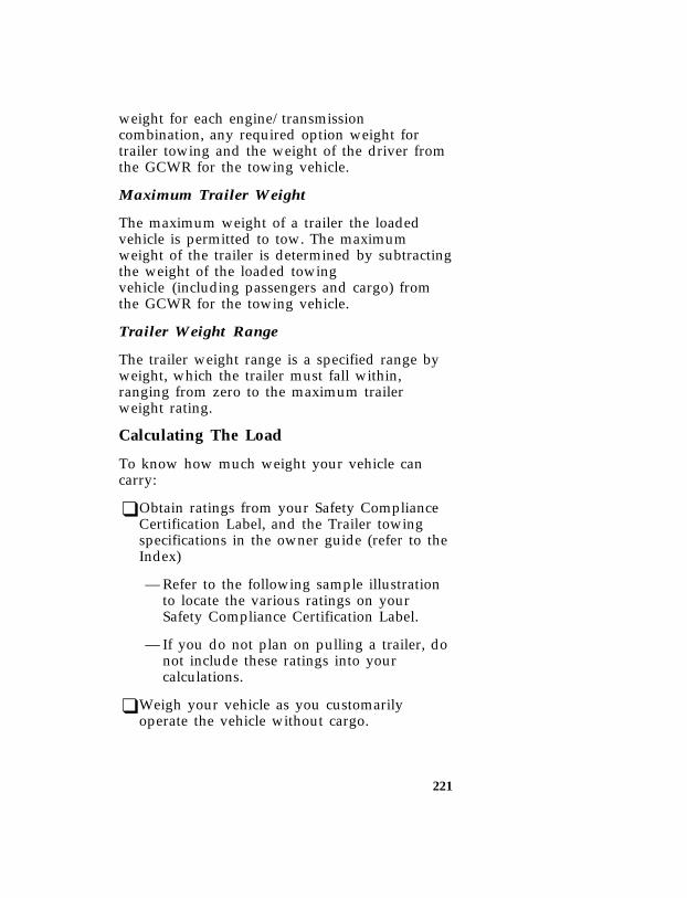
221
weight for each engine/transmissioncombination, any required option weight fortrailer towing and the weight of the driver fromthe GCWR for the towing vehicle.
*[DR31160( ALL)06/92] Maximum Trailer Weight
*[DR31170( ALL)06/92] The maximum weight of a trailer the loadedvehicle is permitted to tow. The maximumweight of the trailer is determined by subtractingthe weight of the loaded towingvehicle (including passengers and cargo) fromthe GCWR for the towing vehicle.
*[DR31180( ALL)06/92] Trailer Weight Range
*[DR31190( ALL)06/92] The trailer weight range is a specified range byweight, which the trailer must fall within,ranging from zero to the maximum trailerweight rating.
*[DR31301( ALL)03/91] Calculating The Load
*[DR31350( ALL)03/91] To know how much weight your vehicle cancarry:
*[DR31401( ALL)12/91] ❑Obtain ratings from your Safety ComplianceCertification Label, and the Trailer towingspecifications in the owner guide (refer to theIndex)
*[DR31450( ALL)09/93] — Refer to the following sample illustrationto locate the various ratings on yourSafety Compliance Certification Label.
*[DR31501( ALL)03/91] — If you do not plan on pulling a trailer, donot include these ratings into yourcalculations.
*[DR31550( ALL)03/91] ❑Weigh your vehicle as you customarilyoperate the vehicle without cargo.
File:ltdrb.exUpdate:Fri Jun 9 15:26:57 1995

222
*[DR31601( ALL)03/91] ❑Subtract the total weight of passengers, driverand optional equipment added by the factory,dealer or aftermarket supplier to determinehow much cargo weight you can carry.
*[DR31650(B FM)03/94]
half page art:0020837-B
Sample label
*[DR31702( ALL)03/91] If you suspect that your payload is excessive,have your vehicle weighed at a highway weighstation or appropriate commercial facility. Weighthe total vehicle and trailer (if applicable), thenseparately weigh the vehicle at the front andrear wheels. And finally, weigh the trailerseparately if applicable.
File:ltdrb.exUpdate:Fri Jun 9 15:26:57 1995
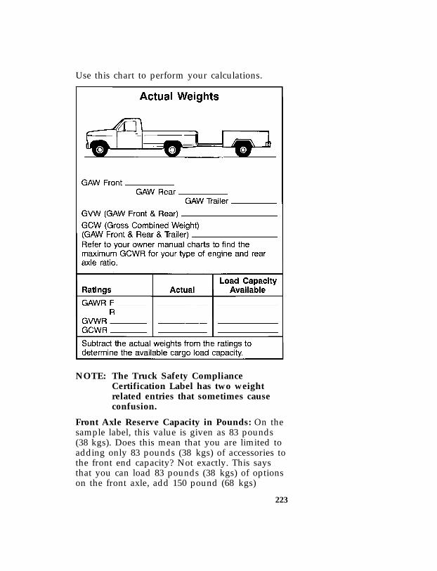
223
*[DR31751( ALL)03/91] Use this chart to perform your calculations.
*[DR31801(B FM)03/94]
twenty-six pica chart:0020838-D
*[DR31851( ALL)03/91] NOTE: The Truck Safety ComplianceCertification Label has two weightrelated entries that sometimes causeconfusion.
*[DR31901( ALL)10/94] Front Axle Reserve Capacity in Pounds: On thesample label, this value is given as 83 pounds(38 kgs). Does this mean that you are limited toadding only 83 pounds (38 kgs) of accessories tothe front end capacity? Not exactly. This saysthat you can load 83 pounds (38 kgs) of optionson the front axle, add 150 pound (68 kgs)
File:ltdrb.exUpdate:Fri Jun 9 15:26:57 1995
224
passengers to all seating positions, and addevenly distributed cargo in the box withoutexceeding the GAWR F.
*[DR31950( ALL)06/92] It is possible to hang heavier equipment on thefront as long as the vehicle owner/operatorcompensates. This can be accomplished, ifnecessary, by carrying fewer passengers, lesscargo or positioning cargo more toward the rear,which has the effect of reducing the load on thefront. Keep in mind that the GAWR F, GAWRR, nor the GVWR should ever be exceeded.
*[DR32001( ALL)05/91] Total Accessory Reserve Capacity in Pounds:On the sample label this value is given as 112pounds (51 kgs). This is a number that is relatedto government crash test standards, and onlyindirectly reflects on the amount of accessoryweight that can be carried.
*[DR32050( ALL)06/94] In the case of both these numbers (83 and 112pounds) (38 and 51 kgs), the important thing toremember is that for safe operation, anowner/operator should calculate the amount andthe distribution of all weights (passengers,accessory equipment and cargo). These combinedweights should fall below the vehicle’s GVWRand GAWR.
*[DR32201( ALL)01/93] Trailers
*[DR32251( ALL)10/94] Towing a trailer safely means having the properweight on the tongue (usually 10% of the trailerweight). Load-equalizing hitches on large rigsmay transfer weight to each of the vehicle’saxles. This weight must be included in capacitycalculations when determining if the vehicle isloaded within safe limits.
*[DR32301( ALL)01/95] If your vehicle exceeds the GVWR, remove cargofrom your vehicle accordingly. If your vehicleexceeds the GAWR for either axle, shift the loador remove cargo accordingly.
File:ltdrb.exUpdate:Fri Jun 9 15:26:57 1995

225
*[DR32350( ALL)02/95] RWARNING
If the GVWR or the GAWR specified onthe Safety Compliance Certification Labelis exceeded, your vehicle may be damagedor you may lose control and injuresomeone.
*[DR32401( ALL)05/95] RWARNING
Towing trailers beyond the maximumrecommended gross trailer weight couldresult in engine damage, transmission/axledamage, structural damage, loss of control,and personal injury.
*[DR32450( ALL)03/91] Using the Safety Compliance Certification Labelfind the axle code number and the engine typefor your vehicle.
*[DR32500( ALL)03/91] Use the appropriate Maximum Gross CombinedWeight Rating (GCWR) chart to find theMaximum GCWR for your type engine and rearaxle ratio.
*[DR32551( ALL)03/91] Subtract your Loaded Vehicle Weight from theMaximum GCWR found in the chart. This is themaximum trailer weight your vehicle can towand must fall below the maximum shown underTrailer Weight on the chart.
File:ltdrb.exUpdate:Fri Jun 9 15:26:57 1995
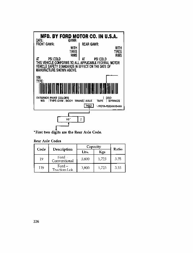
226
[DR33700(B )03/93]
thirty pica chart:0020159-C
File:ltdrb.exUpdate:Fri Jun 9 15:26:57 1995
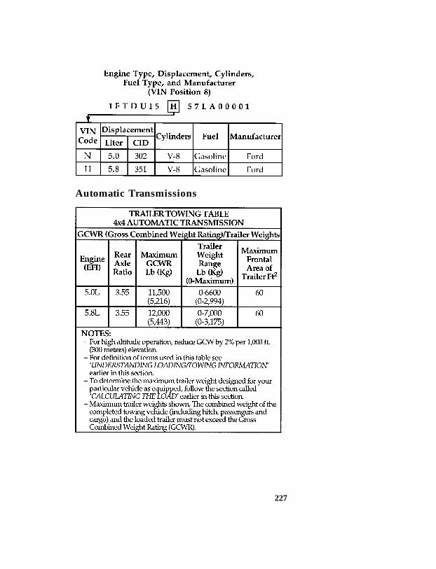
227
[DR33750(B )06/92]
ten pica chart:0020470-B
*[DR33780(B )06/94] Automatic Transmissions
[DR33800(B )04/94]
twenty-two pica chart:0020160-E
File:ltdrb.exUpdate:Fri Jun 9 15:26:57 1995
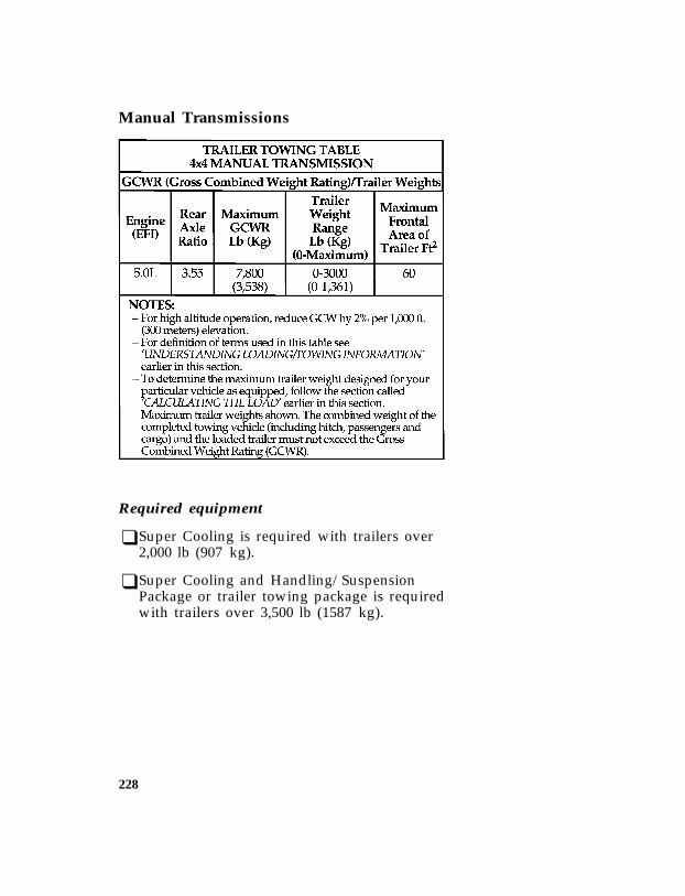
228
*[DR33880(B )04/89] Manual Transmissions
[DR33900(B )03/94]
twenty pica chart:0020161-D
*[DR35500(BEF )02/91] Required equipment
*[DR35700(BEF )01/89] ❑Super Cooling is required with trailers over2,000 lb (907 kg).
*[DR35800(BEF )06/92] ❑Super Cooling and Handling/SuspensionPackage or trailer towing package is requiredwith trailers over 3,500 lb (1587 kg).
File:ltdrb.exUpdate:Fri Jun 9 15:26:57 1995

229
*[DR36500( ALL)01/95] Preparing to Tow
*[DR36550( ALL)01/95] For your safety and for the good of yourvehicle, use the right equipment for the type oftrailer you tow. Also, make sure that all towingequipment is properly attached to your vehicle.If you are not certain that you are using theright equipment in the proper manner, see yourFord or Lincoln-Mercury dealer.
*[DR36600( ALL)01/93] Hitches
*[DR36800(B F )12/91] Do not install a single or multi-clamp typebumper hitch, or a hitch which attaches to theaxle. Underbody mounted hitches are acceptableif installed properly. Follow towing instructionsof a reputable rental agency.
*[DR37000( ALL)12/92] Whenever a trailer hitch and hardware areremoved, make sure all mounting holes in theunderbody are properly sealed to preventnoxious gases or water from entering.
[DR37100(BE )03/93] Trailer Tow/Step bumper
[DR37200(B )03/91] The step bumper has a built-in hitch and onlyrequires a ball with a one inch shank diameter.The step bumper has a limited Class IIIcapability (4,000 lb/1814 kg trailer weight and400 lb/180 kg tongue weight).
File:ltdrb.exUpdate:Fri Jun 9 15:26:57 1995

230
*[DR37550(B F )03/91] NOTE: The rated capacities (as shown in thisguide) for trailer towing with thefactory bumper are only valid whenthe trailer hitch ball is installeddirectly into the ball hole in thebumper. Addition of bracketry to eitherlower the hitch ball position or extendthe hitch ball rearward willsignificantly increase the loads on thebumper and its attachments. This canresult in the failure of the bumper orthe bumper attachments. Use of anytype of hitch extensions should beconsidered abuse.
*[DR37575(B F )03/91] If it is necessary to relocate the trailer hitch ballposition a frame mounted trailer hitch must beinstalled.
*[DR37800( ALL)11/89] Safety Chains
*[DR37900( ALL)12/92] Always use safety chains between your vehicleand trailer. Cross chains under the trailer tongueand allow slack for turning corners. Connectsafety chains to the vehicle frame or hookretainers. Never attach chains to the bumper.
File:ltdrb.exUpdate:Fri Jun 9 15:26:57 1995

231
*[DR38000( ALL)01/93] Trailer Brakes
*[DR38100( ALL)03/95] Separate trailer brakes are required on mosttowed vehicles weighing over 1,500 lb (680 kg).
*[DR38200( ALL)05/95] RWARNING
Do not connect a trailer’s hydraulic brakesystem directly to your vehicle’s brakesystem. Your vehicle may not haveenough braking power and your chancesof having a collision greatly increase.
*[DR38300( ALL)01/93] Trailer Lamps
*[DR38400( ALL)11/89] Make sure your trailer lamps conform to Federaland local regulations.
[DR38417(B F )05/95] Your vehicle has been equipped for use with a4-wire trailer tow electrical system (runninglamps, right hand stop/turn, left handstop/turn, and ground).
*[DR38425(BEF )03/91] Class I and Class II Trailer Tow electrical wiringprovides two circuits (right hand and left hand)to operate trailer stop/turn tail lamps. Eachstop/turn circuit will operate one combinationstop/turn light bulb (# 1157, 3157, 2357, or 3357)on the trailer. Never add more than one trailerlight bulb to one circuit.
[DR38429(B F )05/95] A wire harness (Ford part numberF5TB-13A576-A) has been provided that connectsto the frame wire harness at the rear of thevehicle and is compatible with most 4-wiretrailer tow electrical systems.
[DR38431(B F )05/95] Always check trailer and vehicle functions (i.e.,stop/turn signal, and running lights) beforeoperating your vehicle and trailer.
[DR38433(B F )05/95] If your vehicle fails to function properly, do notoperate your vehicle and trailer until correctionsare made.
File:ltdrb.exUpdate:Fri Jun 9 15:26:57 1995

232
*[DR38450( ALL)05/95] RWARNING
Always replace a fuse with one that hasthe specified amperage rating. Using afuse with a higher amperage rating cancause severe wire damage and could starta fire.
*[DR38500( ALL)01/95] Driving while you tow
*[DR38520( ALL)05/95] Be especially careful when driving while youtow a trailer. Never drive faster than 45 mph(70 km/h) when you tow in hilly country onhot days. Also, anticipate stops so that you canbrake gradually.
%*[DR38540( ALL)01/95] If you use the speed control while you aretowing on very long, steep grades, the speedcontrol may shut off.
*[DR38700( ALL)03/94] If your vehicle is equipped with an Electronic4-Speed Automatic (E4OD or 4R70W)transmission, operate in Overdrive. Refer to theautomatic transmission operation earlier in thischapter.
*[DR38800( ALL)10/94] When descending a steep grade with a trailer,operate in Drive rather than Overdrive. Ifadditional braking is needed, shift the automatictransmission gearshift into 2 (Second) gear or 1(Low).
[DR38810(B F )05/95] If your vehicle is equipped with a manual5-speed transmission, operate in 4th gear.Overdrive (5th) gear should not be used whentowing.
[DR38811(B F )05/95] If additional braking is needed when descendinga steep grade with a trailer, downshift thetransmission into 3rd gear.
File:ltdrb.exUpdate:Fri Jun 9 15:26:57 1995
233
*[DR38925( ALL)01/95] Servicing your vehicle if you tow
*[DR38950( ALL)08/93] If you tow a trailer for a long distance, yourvehicle will need to be serviced more frequentlythan usual. Refer to the Maintenance Schedule andRecord booklet for additional information.
*[DR39000( ALL)01/93] Trailer towing tips
*[DR39100( ALL)11/89] Before starting on a trip, practice turning,stopping and backing in an area away fromheavy traffic. Get to know the “feel” of thevehicle/trailer combination.
*[DR39200( ALL)05/90] Practice backing up. Back up very slowly, withsomeone outside at the rear of your trailer toguide you. Place your hand at the bottom of thesteering wheel and move it in the direction youwant the rear of the trailer to swing. Slightmovement of the steering wheel results in amuch larger movement of the rear of the trailer.
*[DR39300( ALL)11/89] Allow more room for stopping with a trailerattached. Trailer brakes should be applied first,whether manually or automatically controlled,when approaching a stop.
*[DR39400( ALL)11/89] For a good handling truck-trailer combination,the trailer tongue load should be approximately10-15% of the loaded trailer weight.
*[DR39500( ALL)05/95] Make a thorough check of your equipmentbefore starting out on the road. After you havetraveled about 50 miles (80 km) stop in aprotected area and double-check your hitch andelectrical connections. Also check trailer wheellug nuts for tightness.
File:ltdrb.exUpdate:Fri Jun 9 15:26:57 1995

234
*[DR39600( ALL)11/89] When turning, drive slightly beyond the normalturning point so the trailer wheels will clearcurbs or other obstructions.
*[DR39725(B F )03/95] When stopped in traffic for long periods of timein hot weather, place the gearshift selector leverin P (Park) to increase the engine idle speed.This aids in engine cooling and air conditionerefficiency. If the engine overheats, move thefunction selector knob to VENT to stop thecompressor and increase the engine speed for ashort time.
*[DR39900( ALL)05/90] Vehicles with trailers should not be parked on agrade. However, if you must park on a grade,place wheel chocks under the trailer’s wheels asfollows:
*[DR40000( ALL)11/89] ❑Apply the foot service brakes and hold.
*[DR40100( ALL)11/89] ❑Have another person place the wheel chocksunder the trailer wheels.
*[DR40200( ALL)11/89] ❑With the chocks in place, release the footservice brakes, making sure the chocks areholding.
*[DR40300(B F )03/91] ❑For automatic transmissions — apply theparking brake by pressing the service brakepedal down firmly with your right foot whileapplying the parking brake pedal with yourleft foot.
*[DR40400(B F )08/94] For manual transmissions — apply theservice brake and shift into N (NEUTRAL)while still maintaining pressure on the servicebrake pedal. Set the parking brake fully.
File:ltdrb.exUpdate:Fri Jun 9 15:26:57 1995

235
*[DR40500(B F )12/91] ❑Shift an automatic transmission into Park (P).Put the gearshift of a manual transmission inReverse. If your vehicle is equipped withfour-wheel drive make sure the transfer caseis not in Neutral.
*[DR40600( ALL)01/93] To start, after being parked on a grade:
*[DR40700( ALL)11/89] ❑Apply the foot service brakes and hold
*[DR40800( ALL)11/89] ❑Start the engine
*[DR40900( ALL)11/89] ❑Shift transmission into gear and release theparking brake
*[DR41000( ALL)11/89] ❑Release the foot service brakes and move thevehicle uphill to free the wheel chocks
*[DR41100( ALL)11/89] ❑Apply the foot service brakes and hold whileanother person retrieves the chocks.
*[DR41260(B F )02/92] Snowplowing
*[DR41275(B )01/93] RWARNING
Do not use this vehicle for snowplowing.
File:ltdrb.exUpdate:Fri Jun 9 15:26:57 1995

237
Roadside Emergencies
%*[RE00400( ALL)03/95] Jump-Starting Your Vehicle
*[RE00500( ALL)01/95] Your vehicle’s battery may die if you leave thelights on or any electrical equipment on afteryou turn the engine off. If this happens, youmay be able to jump-start from a booster batteryto start your vehicle.
*[RE00600( ALL)02/95] RWARNING
The gases around the battery can explodeif exposed to flames, sparks, or litcigarettes. An explosion could result ininjury or vehicle damage.
*[RE00700( ALL)02/95] RWARNING
To protect yourself when charging abattery, always shield your face and eyes.Make sure that you can breathe fresh air.
%*[RE00800( ALL)05/95] RWARNING
Applying too much pressure on the endswhen lifting a battery could cause acid tospill. Lift the battery with a carrier orwith your hands on the opposite corners.
%*[RE00900( ALL)05/95] RWARNING
Batteries contain sulfuric acid which burnsskin, eyes, and clothing.
File:ltreb.exUpdate:Fri Jun 9 15:25:48 1995

238
*[RE00925( ALL)05/95] If the acid touches someone’s skin, eyes, orclothing, immediately flush the area with waterfor at least 15 minutes. If someone swallows theacid, have him or her drink lots of milk or waterfirst, then Milk of Magnesia, a beaten egg, orvegetable oil. Call a doctor immediately.
*[RE00950( ALL)12/89] RWARNING
Do not push-start your vehicle. You coulddamage the catalytic converter. For furtherinformation, see Jumper Cables in theIndex.
*[RE01000( ALL)03/95] To avoid damaging your vehicle or your battery,and to avoid injury to yourself, follow thesedirections for preparing your vehicle tojump-start and connecting the jumper cables inthe order they are given. If in doubt, call forroad service.
*[RE01100( ALL)03/95] Preparing Your Vehicle
*[RE01200( ALL)03/95] 1. Your vehicle has a 12-volt starting system, soyou need to use a 12-volt jumper system.You will damage your starting motor,ignition system, and other electrical parts ifyou connect them to a 24-volt power supply(either two 12-volt batteries in series or a24-volt generator set).
*[RE01300( ALL)03/95] 2. Do not disconnect the battery of the disabledvehicle. You could damage the vehicle’selectrical system.
*[RE01400( ALL)04/95] 3. Park the booster vehicle close to the hood ofthe disabled vehicle. Make sure the vehiclesdo not touch each other. Set the parkingbrake on both vehicles and stay clear of theengine cooling fan and other moving parts.
File:ltreb.exUpdate:Fri Jun 9 15:25:48 1995

239
*[RE01500( ALL)03/95] 4. Check all battery terminals and remove anyexcessive corrosion before you attach thejumper cables.
*[RE01600( ALL)02/95] 5. Turn on the heater fan in both vehicles.Turning on the fan helps protect theelectrical system from voltage surges. Turnoff all other switches and lights in bothvehicles to prevent possible damage to eithervehicle’s electrical systems.
%*[RE01700( ALL)05/95] Connecting the jumper cables
*[RE01800( ALL)03/95] 1. Connect one end of the first jumper cable tothe positive (+) terminal of the dischargedbattery. (You can connect either jumper cableto the positive (+) terminal, as long as youuse the same cable for both positiveterminals.) Most jumper cables have a redcable and a black cable. The red cable isgenerally used for the positive terminals andthe black for the negative ones.
*[RE01900( ALL)04/95] 2. Connect the other end of the first cable tothe positive (+) terminal of the boosterbattery.
*[RE02000( ALL)05/95] 3. Connect one end of the second cable to thenegative (-) terminal of the booster battery— NOT to the discharged battery.
*[RE02100( ALL)04/95] 4. Connect the other end of the second cable toa good metallic surface on the engine orframe of the disabled vehicle.
*[RE02200( ALL)05/95] RWARNING
Do not connect the end of the secondcable to the negative (-) terminal of thebattery to be jumped. A spark may causean explosion of the gases that surroundthe battery.
File:ltreb.exUpdate:Fri Jun 9 15:25:48 1995

240
*[RE02300( ALL)06/93]
one third page art:0020262-C
Attaching jumper cables
*[RE02500( ALL)03/95] Jump-Starting
*[RE02600( ALL)03/95] 1. Make sure that the jumper cables are not inthe way of moving engine parts, then startthe booster vehicle. Run the engine at amoderate speed.
*[RE02700( ALL)03/95] 2. Let the discharged battery charge for a fewminutes and then start the disabled vehicle.It may take a couple of tries before thevehicle starts. If the vehicle does not startafter several attempts, there may be adifferent problem.
*[RE02800( ALL)03/95] 3. When both vehicles are running, let themidle for a few minutes to charge thedischarged battery.
%*[RE02900( ALL)03/95] Removing jumper cables
*[RE03000( ALL)03/95] 1. Always remove the jumper cables in thereverse order. Remove the negative (s) endof the jumper cable from the metallic surfaceon the engine or frame of the disabledvehicle.
*[RE03100( ALL)05/95] 2. Remove the negative (s) cable from thebooster battery.
*[RE03200( ALL)03/95] 3. Remove the positive (+) cable from thebooster battery.
File:ltreb.exUpdate:Fri Jun 9 15:25:48 1995

241
*[RE03400( ALL)05/95] 4. Remove the other end of the positive (+)cable from the discharged battery.
*[RE03500( ALL)04/95] After the vehicle is started, let it idle for a whileto let the engine “relearn” its idle conditions.Drive it around for a while with all electricalaccessories turned off to let the battery recharge.You may need to use a battery charger to fullyrecharge the battery.
*[RE03550( ALL)03/95] If you need to replace your battery, see Batteryin the Servicing Your Vehicle chapter.
%*[RE03600( ALL)03/95] Changing a Tire
*[RE03700( ALL)01/95] If you get a flat tire while you are driving, donot apply the brake heavily. Instead, graduallydecrease the speed. Hold the steering wheelfirmly and slowly move to a safe place on theside of the road. Park on a level spot, turn offthe ignition, set the parking brake, and turn onthe hazard flashers.
*[RE03800( ALL)03/95] The Conventional Spare Tire
*[RE03900(BEF )01/95] If you have the conventional spare tire, you canuse it as a spare or as a regular tire. This sparetire is identical to the other tires that come withyour vehicle, although the wheel may not match.
*[RE04275(BEF )05/95] RWARNING
To avoid injury, never run the enginewith one wheel off the ground, such aswhen changing a tire.
*[RE04280(BEF )10/94] Extended use of other than matching size sparetires on a Traction-Lok axle could result in apermanent reduction in effectiveness. This loss ofeffectiveness does not affect normal driving andshould not be noticeable to the driver.
File:ltreb.exUpdate:Fri Jun 9 15:25:48 1995
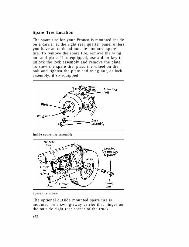
242
*[RE05100(BEF )03/95] Spare Tire Location
[RE07700(B )05/90] The spare tire for your Bronco is mounted insideon a carrier at the right rear quarter panel unlessyou have an optional outside mounted sparetire. To remove the spare tire, remove the wingnut and plate. If so equipped, use a door key tounlock the lock assembly and remove the plate.To stow the spare tire, place the wheel on thebolt and tighten the plate and wing nut, or lockassembly, if so equipped.
[RE07800(B )02/89]
one third page art:0020271-A
Inside spare tire assembly
[RE08100(B )05/90]
one third page art:0020322-C
Spare tire mount
[RE08300(B )01/89] The optional outside mounted spare tire ismounted on a swing-away carrier that hinges onthe outside right rear corner of the truck.
File:ltreb.exUpdate:Fri Jun 9 15:25:48 1995

243
[RE08400(B )01/89] To remove the outside mounted spare tire:
[RE08450(B )05/90]
quarter page art:0020275-A
Removal and installation of spare tire cover
[RE08500(B )05/90] 1. Lift the edge of the spare tire cover behindthe top of the tire and slide the cover overthe tire and downward.
[RE08600(B )01/89] 2. Remove the security lock, retaining nut andmounting plate.
[RE08700(B )01/89] 3. Slide the tire outward and lift off the carrier.
[RE08800(B )01/89] If you have difficulty removing the retainingnut, turn the nut counterclockwise by using thetapered end of the lug nut wrench in one of theslots at either end of the retaining nut.
[RE08900(B )05/89] To stow the outside mounted spare tire:
[RE09000(B )01/89] 1. Place the spare tire on the carrier over thebolt, styled side in.
[RE09100(B )01/89] 2. Place the plate on the bolt and tighten theretaining nut securely.
[RE09200(B )01/89] 3. Install security lock.
[RE09300(B )02/89] 4. Position the cover over the edge of the tirewith the drainage eyelet at the bottom. Slidethe cover upward, wrapping it around theedge of the tire until the cover is completelyfitted.
File:ltreb.exUpdate:Fri Jun 9 15:25:48 1995

244
[RE09400(B )05/90] NOTE: If your truck has optional aluminumwheels, you should slip the anti-scratchspacer over the “J” bolt between thetire and carrier to prevent scratchingthe aluminum styled-side surface.
[RE09500(B )05/91]
one third page art:0020273-C
Optional outside mounted spare tire and carrier
*[RE15100(BEF )05/95] RWARNING
Make sure the spare tire and jackingequipment are stowed and secured in theproper storage location.
%*[RE15200( ALL)03/95] Preparing to Change the Tire
*[RE15250( ALL)12/91] NOTE: To lift your vehicle by other than thefront or rear jacking points, be sure touse only hoist adapters with a widecontact surface.
*[RE15300(B F )03/91] 1. Make sure that your vehicle will not moveor roll. If you have an automatictransmission, put the gearshift in Park. Ifyou have a manual transmission, put thegearshift in Reverse. Set the parking brakeand block the wheel that is diagonallyopposite the tire that you are changing.
*[RE15335(B F )12/91] NOTE: Make sure the ignition is in the OFFposition.
File:ltreb.exUpdate:Fri Jun 9 15:25:48 1995

245
*[RE15350(B F )06/94] If you have a four-wheel drive vehicles withmanual locking hubs, put transfer case lever in2H, 4H, or 4L.
*[RE15375(B F )05/95] When one of the back wheels is off the ground,the transmission alone will not prevent thevehicle from moving or slipping off the jack,even if the vehicle is in P (Park) or 1 (First). Toprevent the vehicle from moving when youchange a tire, be sure the parking brake is set,then block the wheel (both directions) that isdiagonally opposite (other side and end of thevehicle) to the tire that is being changed.
*[RE15400(B F )05/95] RWARNING
If the vehicle slips off the jack, you orsomeone else could be seriously injured.
[RE15435(B F )05/95] When the transfer case is in the N (Neutral)position, the engine and transmission aredisconnected from the rest of the driveline.Therefore, the vehicle is free to roll even if theautomatic transmission is in P (Park) or themanual transmission is in gear.
*[RE15440(B F )05/95] RWARNING
Do not leave the vehicle unattended withthe transfer case in the N (Neutral)position. Always set the parking brakefully and turn off the ignition whenleaving the vehicle.
*[RE15550(BEF )05/95] 2. Get out the spare tire and jack.
*[RE15800(B F )10/92] The jack and lug wrench are stowed under thehood on the right front fender inner panel, andthe jack handle is on the radiator support.
File:ltreb.exUpdate:Fri Jun 9 15:25:48 1995

246
*[RE15900(B F )06/93]
half page art:0020286-E
Jack and assembly location
*[RE16800(BEF )12/91] 3. Use the tapered end of the lug nut wrenchto unscrew wheel ornaments attached byretaining screws. Remove any wheel trim.Insert the tapered end of the lug nut wrenchbehind wheel covers or hubcaps and twistoff.
*[RE16900(BEF )10/89] 4. Loosen the wheel nuts by pulling up on thehandle of the lug nut wrench about one-halfturn (counterclockwise). Do not remove thewheel lug nuts until you raise the tire off theground.
File:ltreb.exUpdate:Fri Jun 9 15:25:48 1995

247
%*[RE16950(BEF )05/95] Removing and Replacing the Tire
[RE17100(B F )02/95] 1. Insert the jack handle into the jack and usethe handle to slide the jack under thevehicle.
*[RE17175(BEF )05/95] RWARNING
To avoid injury, never run the enginewith one wheel off the ground, such aswhen changing a tire.
*[RE17200(BEF )05/95] RWARNING
To lessen the risk of personal injury, donot put any part of your body under thevehicle while changing a tire. Do not startthe engine when your vehicle is on thejack. The jack is only meant for changingthe tire.
*[RE17300(BEF )01/95] 2. Positioning the jack
[RE18000(B )01/89] a. To raise a front wheel or a rear wheel,place the jack as shown in the followingillustrations.
[RE18100(B )01/89]
one third page art:0020295-A
Jacking point
File:ltreb.exUpdate:Fri Jun 9 15:25:48 1995

248
[RE18551(BE )11/89]
one third page art:0020296-A
Jacking point
*[RE18701(B )08/91] b. Turn the jack handle clockwise until thewheel is completely off the ground.
*[RE21151(BEF )10/92]
one third page art:0020939-B
*[RE21400(BEF )01/95] 3. Remove the lug nuts with the lug nutwrench.
*[RE21500(BEF )01/95] 4. Replace the flat tire with the spare tire.
*[RE21700(B )01/95] 5. Thread the lug nuts on the wheel studs withthe beveled face toward the wheel. Use thelug nut wrench to screw the lug nut snugagainst the wheel but do not tighten.
*[RE22200(BEF )01/95] 6. Lower the vehicle by turning the jack handlecounterclockwise.
File:ltreb.exUpdate:Fri Jun 9 15:25:48 1995
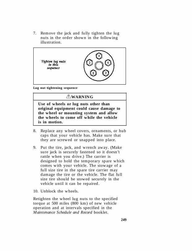
249
*[RE22300(BEF )01/95] 7. Remove the jack and fully tighten the lugnuts in the order shown in the followingillustration.
*[RE22400(B )12/89]
quarter page art:0020312-B
Lug nut tightening sequence
*[RE23400(BEF )05/95] RWARNING
Use of wheels or lug nuts other thanoriginal equipment could cause damage tothe wheel or mounting system and allowthe wheels to come off while the vehicleis in motion.
*[RE23500(BEF )01/95] 8. Replace any wheel covers, ornaments, or hubcaps that your vehicle has. Make sure thatthey are screwed or snapped into place.
[RE23615(BEF )02/95] 9. Put the tire, jack, and wrench away. (Makesure jack is securely fastened so it doesn’trattle when you drive.) The carrier isdesigned to hold the temporary spare whichcomes with your vehicle. The stowage of afull size tire in the spare tire carrier maydamage the tire or the vehicle. The flat fullsize tire should be stowed securely in thevehicle until it can be repaired.
*[RE23700(BEF )01/95] 10. Unblock the wheels.
*[RE23800(B )06/93] Retighten the wheel lug nuts to the specifiedtorque at 500 miles (800 km) of new vehicleoperation and at intervals specified in theMaintenance Schedule and Record booklet.
File:ltreb.exUpdate:Fri Jun 9 15:25:48 1995

250
*[RE24200( ALL)10/89] Also retighten to the specified torque at 500miles (800 km) of operation after any wheelchange or any time the lug nuts are loosened.
*[RE24301( ALL)05/95] RWARNING
Failure to retighten wheel lug nuts atmileages specified could allow wheels tocome off while the vehicle is in motion.
[RE24330(B )02/89]
eight pica chart:0020314-A
*[RE24397(BEF )02/95] If the Engine Cranks But DoesNot Start or Does Not Start Aftera Collision
*[RE24400(BEF )04/95] The Fuel Pump Shut-off Switch
*[RE24500(BEF )03/95] If the engine cranks but does not start or if youhave had a collision, the fuel pump shut-offswitch may have been triggered. The shut-offswitch is a device that stops the fuel pumpwhen your vehicle has been involved in asubstantial jolt.
*[RE24600(BEF )01/95] For information on how to check and reset thefuel pump shut-off switch, see Fuel pump shut-offswitch in the Index.
File:ltreb.exUpdate:Fri Jun 9 15:25:48 1995

251
*[RE24700( ALL)05/95] Towing Your Vehicle
*[RE24875( ALL)] If you need to have your vehicle towed, contacta professional towing service or, if you are amember, your roadside assistance center.Recommended towing options include wheel lifttowing or flat bed towing.
[RE24925(ALL )02/95]
half page art:0001463-A
*[RE24950( ALL)] When calling for a tow truck, tell the operatorwhat kind of vehicle you have. A towing
File:ltreb.exUpdate:Fri Jun 9 15:25:48 1995
252
manual is available from Ford Motor Companyfor all authorized tow truck operators. Haveyour tow truck driver refer to this manual forthe proper hook-up and towing procedures foryour vehicle.
*[RE26300(B F )06/94] Towing Four-Wheel Drive Vehicles With aLever-Operated Transfer Case
*[RE26400(B F )06/94] ❑Place transmission gearshift (automatic ormanual) in N (Neutral).
*[RE26425(B F )06/94] ❑Lock steering wheel straight ahead if vehicleis to be towed with rear wheels off theground.
*[RE26450(B F )12/89] ❑Set manual locking hubs in FREE position ordisengage the automatic locking hubs byshifting the transfer case to 2H and drive thevehicle in the opposite direction for aminimum of 10 feet (3 meters) in a straightline.
*[RE26475(B F )06/94] NOTE: Confirm by observation that the frontdriveshaft is not rotating prior totowing with the rear wheels off theground.
*[RE26500(B F )06/94] ❑Place transfer case in N (Neutral).
*[RE26615(B F )03/91] NOTE: The transfer case neutral setting islocated between 4H and 4L. In order toplace the transfer case in neutral, firstplace the lever in the 4H position, thenpush down (toward the ground) on theshift knob and at the same time pullslightly rearward until the lever isbetween the 4H and 4L position. Withthe ignition in the on position, both4x4 and LOW RANGE indicator lightswill be off when the transfer case is inneutral. These lights will also be offwhen the transfer case is in the 2Hposition.
File:ltreb.exUpdate:Fri Jun 9 15:25:48 1995
253
*[RE26650(B F )06/94] There are no wrecker or recreational vehicletowing restrictions on method or distance if theabove preparations are made.
*[RE26700(B F )06/94] ❑Vehicle speed should not exceed 55 mph(88 km/h). This applies with the front wheelsoff the ground, the rear wheels off theground, or both front and rear wheels on theground.
*[RE26800(B F )06/94] Towing Four-Wheel Drive Vehicles WithTouch Drive Electric Shift Transfer Case
*[RE26900(B F )06/94] ❑Place transmission gearshift (automatic ormanual) in N (Neutral).
*[RE27000(B F )05/90] ❑Place transfer case in 2H.
*[RE27050(B F )05/90] NOTE: Both the 4 x 4 and LOW RANGEindicator lights in the instrument panelwill be off when the transfer case is in2H.
*[RE27200(B F )06/94] ❑Lock steering wheel straight ahead if vehicleis to be towed with rear wheels off theground.
*[RE27301(B F )06/94] ❑When towing your vehicle with the rearwheels off the ground, the front axleautomatic locking hubs must first bedisengaged by shifting the transfer case to 2Hand moving the vehicle forward for aminimum of 10 feet (3 meters) in a straightline. Do not exceed a vehicle speed of55 mph (88 km/h) while towing.
*[RE27350(B F )06/94] NOTE: Confirm by observation that the frontdriveshaft is not rotating prior totowing with the rear wheels off theground.
File:ltreb.exUpdate:Fri Jun 9 15:25:48 1995

254
*[RE27400(B F )11/92] ❑When towing your vehicle with the rearwheels on the ground or all four wheels onthe ground and the driveshafts connected, donot exceed 35 mph (56 km/h) ortransmission damage could result. If adistance of 50 miles (80 km) is exceeded,disengage the automatic locking hubs anddisconnect the rear driveshaft from the axleand secure. (Max speed 55 mph [88 km/h]with driveshafts disconnected.)
*[RE27500(BEF )03/91] RWARNING
Never use a tow bar that attaches to thebumper when you tow your vehicle. Thiscould damage the bumper and cause anaccident.
File:ltreb.exUpdate:Fri Jun 9 15:25:48 1995

255
Customer Assistance
%*[HS00205( ALL)06/94] Roadside Assistance
*[HS00210( ALL)05/95] Ford Motor Company has set up a 24-hour,seven-day-a-week hotline with trained operatorsthat put you in touch with the help you need ifyou experience a problem with your vehicle.This complimentary service is provided to youthroughout your warranty period of 3 years or36,000 miles (3 years or 60,000 km), whichevercomes first. To purchase Roadside Assistancecoverages beyond this period, through FordAuto Club, contact your Ford orLincoln-Mercury dealer (not available inCanada).
*[HS00215( ALL)06/94] Roadside Assistance will cover the following:
*[HS00220( ALL)06/94] ❑Mount your spare if you have a flat tire.
*[HS00225( ALL)06/94] ❑ Jump-start your battery if it is dead.
*[HS00230( ALL)06/94] ❑Unlock your vehicle if you are locked out.
*[HS00235( ALL)06/94] ❑Bring you fuel if you run out.
*[HS00240( ALL)06/94] ❑Tow your vehicle if you are stranded. Evennon-warranty related tows, like accidents orgetting stuck in mud or snow, are covered(some exclusions apply, such as impoundtowing and repossession).
File:lthsb.exUpdate:Fri Jun 9 15:25:09 1995

256
*[HS00245( ALL)06/94] How to use Roadside Assistance
*[HS00250( ALL)06/94] Your Roadside Assistance identification card canbe found in the Owner Guide portfolio in yourglove compartment. Complete the card and placeit in your wallet for quick reference.
*[HS00255( ALL)04/95] To receive roadside assistance in the UnitedStates call 1-800-241-FORD (in Canada call1-800-665-2006).
*[HS00260( ALL)04/95] Should you need to arrange for roadsideassistance yourself, Ford Motor Company willreimburse the reasonable cost. To obtaininformation about reimbursement call1-800-241-FORD (in Canada call 1-800-665-2006).
*[HS00300( ALL)01/95] If You Have a Service Problem
*[HS00400( ALL)01/95] Ford Motor Company has authorized Ford andLincoln-Mercury dealerships that can serviceyour vehicle for you. This chapter tells you howto get service or maintenance for your vehicle.
%*[HS00525( ALL)03/95] Service/Maintenance Concerns (U.S. orCanada)
*[HS00600(BEF )04/95] Ford recommends taking your vehicle to yourselling dealer who wants to ensure yourcontinued satisfaction. You may, however, takeyour vehicle to any authorized Ford orLincoln-Mercury dealer. In most cases, yourdealer will be able to resolve your concern.
*[HS00700( ALL)03/95] If you are not satisfied with the service youreceived from your dealership’s servicedepartment, talk to the service manager at thedealership. If you still are not satisfied, talk tothe owner or general manager of the dealership.In most cases, you will have your concernresolved at this level.
File:lthsb.exUpdate:Fri Jun 9 15:25:09 1995

257
*[HS01000( ALL)03/95] If you are away from home when your vehicleneeds to be serviced, or if you need more helpthan the dealer gave you, contact the FordCustomer Assistance Center to find anauthorized dealership that may be able to help.
*[HS01010( ALL)04/95] In the U.S., contact:
%*[HS01025( ALL)03/95]
one inch art:0060100-E
*[HS01050( ALL)03/95] If you live in Canada and have any questions orconcerns that the dealership cannot answer,contact the Customer Assistance Centre.
%*[HS01075( ALL)04/95]
one inch art:0060101-C
*[HS01200( ALL)04/95] Please have the following information availablewhen contacting Ford Customer Assistance:
*[HS01300( ALL)04/95] ❑your telephone number (both business andhome)
*[HS01400( ALL)04/95] ❑ the name of the dealer and the city where thedealership is located
*[HS01500( ALL)03/95] ❑ the year and make of your vehicle
*[HS01550( ALL)03/95] ❑ the date purchased
*[HS01600( ALL)03/95] ❑ the current mileage on your vehicle
File:lthsb.exUpdate:Fri Jun 9 15:25:09 1995

258
*[HS01700( ALL)03/95] ❑your Vehicle Identification Number (VIN)(listed on your owner card)
*[HS02200( ALL)03/95] If you still have a service or product complaint,you may wish to contact the Dispute SettlementBoard (U.S. only) or the Canadian Motor VehicleArbitration Plan (CAMVAP) in Canada.
%*[HS02300( ALL)02/95] The Dispute Settlement Board(U.S. Only)
*[HS02400( ALL)03/95] The Dispute Settlement Board is a voluntary,independent dispute-settlement programavailable free to owners or lessees of qualifyingFord Motor Company vehicles.
*[HS02500( ALL)01/95] The Dispute Settlement Board may not beavailable in all states. Ford Motor Companyreserves the right to change eligibilitylimitations, modify procedures and/or todiscontinue this process at any time withoutnotice and without incurring obligations.
*[HS02600( ALL)01/95] What Kind of Cases Does the BoardReview?
*[HS02700( ALL)03/95] The Board reviews all product performance andservice complaints on Ford, Mercury and LincolnCars and Ford and Mercury Light Trucks underwarranty that have not been resolved by adealer or Ford Motor Company.
*[HS02750( ALL)03/95] The Board does not review issues involving:
*[HS02800( ALL)01/95] ❑A non-Ford product
*[HS02900( ALL)01/95] ❑A non-Ford dealership
*[HS03100( ALL)01/95] ❑A vehicle sales transaction
*[HS03200( ALL)01/95] ❑A request for reimbursement of consequentialexpenses unless incidental to a service orproduct complaint being reviewed
*[HS03300( ALL)01/95] ❑ Items not covered by your warranty
File:lthsb.exUpdate:Fri Jun 9 15:25:09 1995

259
*[HS03400( ALL)01/95] ❑Alleged liability claims
*[HS03450( ALL)01/95] ❑Property damage where such damage issignificant when compared to the economicloss alleged under the warranty dispute
*[HS03500( ALL)01/95] ❑Cases currently in litigation
*[HS03600( ALL)01/95] ❑Vehicles not used primarily for personal,family, or household purposes
*[HS03650( ALL)01/95] NOTE: Complaints involving vehicles onwhich applicable express written newvehicle warranties have expired atreceipt of your application are noteligible. Eligibility may differaccording to state law. For example, seethe unique brochure for Californiapurchasers/lessees.
*[HS03700( ALL)04/95] How Does the Board Work?
*[HS03800( ALL)04/95] The Board has four members:
*[HS03900( ALL)04/95] ❑ three consumer representatives
*[HS04000( ALL)04/95] ❑a Ford or Lincoln-Mercury dealer
*[HS04200( ALL)04/95] Consumer candidates for Board membership arerecruited and trained by an independentconsulting firm. Dealers are chosen because oftheir business leadership qualities.
*[HS04300( ALL)04/95] If the involved vehicle is within 36 months and36,000 miles of the date of delivery (warrantystart date), you have a right to make an oralpresentation before the Board by indicating yourchoice on the application. Also, oralpresentations may be requested by the Board. Adecision is made by the Board by simplemajority vote.
*[HS04350( ALL)04/95] Board members review all the materials relatedto each complaint and, based on the availableinformation, arrive at a fair and impartial
File:lthsb.exUpdate:Fri Jun 9 15:25:09 1995

260
decision. Decisions are based on the writtenstatements and any oral presentations made byeach of the involved parties.
*[HS04400( ALL)04/95] Because the Board usually meets only once amonth, some cases will take longer than 30 daysto be reviewed. The Board will make everyeffort to resolve each case within 40 days after itreceives the customer application form.
*[HS04500( ALL)04/95] After your case has been reviewed, the Boardwill mail you its decision in writing. It will alsoprovide you with a form to indicate youracceptance or rejection of an award decision. Thedecisions of the Board are binding on the dealerand Ford, but customers may have other optionsavailable to them under state or federal law.
*[HS04600( ALL)04/95] The decisions of the Board, however, may beintroduced into evidence by any party insubsequent legal proceedings that may beinitiated.
*[HS04700( ALL)01/95] How Do You Contact the Board?
*[HS04800( ALL)04/95] Write to the Board at the following address torequest a brochure/application. You will be senta brochure and a one-page customer applicationform. The form should be completed and mailedto the same address.
*[HS04900( ALL)02/93]
one inch art:0060102-B
File:lthsb.exUpdate:Fri Jun 9 15:25:09 1995
261
*[HS05100( ALL)04/95] What is the Review Process?
*[HS05200( ALL)04/95] Your application will be reviewed and if it isdetermined to be eligible, you will receive anacknowledgment indicating the file numberassigned to your application and the local Boardaddress. At the same time, your dealer and FordMotor Company representative are asked tosubmit statements.
*[HS05300( ALL)04/95] To review your case properly, the Board needsthe following information:
*[HS05400( ALL)04/95] ❑ legible copies of all documents andmaintenance or repair orders that relate tothe case
*[HS05500( ALL)04/95] ❑ the year, make, model, and vehicleidentification number
*[HS05600( ALL)04/95] ❑ the date you bought your vehicle
*[HS05700( ALL)04/95] ❑ the date of repair and the mileage at the timeof repair
*[HS05800( ALL)04/95] ❑ the current mileage
*[HS05900( ALL)04/95] ❑ the name of the dealer who sold you thevehicle or who serviced your vehicle
*[HS06000( ALL)04/95] ❑a brief description of your unresolvedcomplaint
*[HS06100( ALL)05/95] ❑a brief summary of actions that were takenwith the dealer and Ford Motor Company
*[HS06200( ALL)05/95] ❑ the names (if known) of all people youcontacted at the dealership
*[HS06300( ALL)04/95] ❑a description of the action you want done toresolve your concern.
*[HS06305( ALL)04/95] Should your application NOT qualify for review,an explanation will be mailed to you.
File:lthsb.exUpdate:Fri Jun 9 15:25:09 1995

262
*[HS06310( ALL)04/95] Ford of Canada does not have a DisputeSettlement Board. If you have a problem thatcannot be resolved by an agreement among you,Ford of Canada, and the Ford dealer, contact theCanadian Motor Vehicle Arbitration Plan(CAMVAP). In many areas of Canada, CAMVAPwill help resolve the problem and, if necessary,will arrange for the matter to be arbitrated.
*[HS06320( ALL)04/95] Reporting Safety Defects(U.S. Only)
*[HS06340( ALL)01/95] If you believe that your vehicle has a defectwhich could cause a crash or could cause injuryor death, you should immediately inform theNational Highway Traffic Safety Administration(NHTSA) in addition to notifying Ford MotorCompany.
*[HS06360( ALL)01/95] If NHTSA receives similar complaints, it mayopen an investigation, and if it finds that asafety defect exists in a group of vehicles, it mayorder a recall and remedy campaign. However,NHTSA cannot become involved in individualproblems between you, your dealer, or FordMotor Company.
*[HS06380( ALL)01/95] To contact NHTSA, you may either call the AutoSafety Hotline toll-free at 1-800-424-9393 (or366-0123 in the Washington, D.C. area) or writeto: NHTSA, U.S. Department of Transportation,400 Seventh Street, Washington D.C. 20590. Youcan also obtain other information about motorvehicle safety from the Hotline.
File:lthsb.exUpdate:Fri Jun 9 15:25:09 1995

263
%*[HS06400( ALL)05/95] Getting Help Outside the U.S.and Canada
*[HS06500( ALL)05/95] Before you export your vehicle to a foreigncountry, contact the appropriate foreign embassyor consulate to make sure local regulations donot prevent you from registering your vehicle.Officials at the embassy can also help you decidewhether you should import your vehicle to thatcountry.
*[HS06600( ALL)05/95] Officials at the embassy or consulate can tell youwhere to get unleaded fuel. If you cannot getunleaded fuel or can get only fuel with ananti-knock index that is lower than your vehicleneeds, contact a district or owner relations officebefore you leave the U.S. or Canada.
*[HS06700( ALL)05/95] Use of leaded fuel in your vehicle without aproper conversion may damage the effectivenessof your emissions control system and may causeengine knocking or serious engine damage. FordMotor Company is not responsible for anydamage that is caused by use of improper fuel.
*[HS06800( ALL)05/95] You may also have difficulty importing yourvehicle back into the U.S. if you use leaded fuel.
*[HS06900( ALL)05/95] If your vehicle must be serviced while you aretraveling or living in Central or South America,the Caribbean, or the Middle East, contact thenearest Ford dealership. If the dealership cannothelp you, write to:
*[HS07000( ALL)05/95]
one inch art:0060103-H
File:lthsb.exUpdate:Fri Jun 9 15:25:09 1995

264
*[HS07100( ALL)05/95] If you are in other foreign countries, contact thenearest Ford dealership. If the dealership cannothelp you, they can direct you to the appropriateFord affiliate office.
*[HS07200( ALL)05/95] If you buy your vehicle in North America andthen relocate outside of the U.S. or Canada,register your Vehicle Identification Number andnew address with Ford Motor Company ExportOperations.
*[HS07700( ALL)05/95] Ford of Canada CustomerAssistance
*[HS07800( ALL)03/95] Ford Motor Company of Canada, Limited
*[HS07850( ALL)03/95] If you live in Canada and have any questions orconcerns that the dealership cannot answer,contact the Customer Assistance Centre.
*[HS07950( ALL)03/95]
one inch art:0060101-C
File:lthsb.exUpdate:Fri Jun 9 15:25:09 1995

265
%*[HS08100( ALL)03/95] Canadian Motor Vehicle Arbitration Plan(CAMVAP)
*[HS08200( ALL)03/95] If a specific item of concern arises, where asolution cannot be reached between a vehicleowner, Ford of Canada, and/or one of itsdealers (that all parties can agree upon), theowner may wish to use the services offered bythe Canadian Motor Vehicle Arbitration Plan(CAMVAP).
*[HS08300( ALL)05/95] CAMVAP uses the services of ProvincialAdministrators to assist consumers in schedulingand preparing for their arbitration hearings.However, before you can proceed withCAMVAP you must follow your manufacturer’sdispute resolution process as outlined under“Service/Maintenance Concerns (U.S. orCanada)” earlier in this chapter.
*[HS08400( ALL)05/95] Consumers wishing to obtain further informationabout the program can obtain an informationbooklet from your dealer or contact theProvincial Administrator, Canadian MotorVehicle Arbitration Plan, at the address ortelephone number shown below.
*[HS08450( ALL)05/95] O & P Services595 Bay Street — Suite 300Toronto, OntarioM5G 2C2Telephone 1 (800) 207-0685
File:lthsb.exUpdate:Fri Jun 9 15:25:09 1995
267
Accessories
*[AC00400( ALL)03/95] Ford Accessories for Your Vehicle
*[AC00500( ALL)04/95] A wide selection of accessories is availablethrough your local authorized dealer. These fineaccessories have been engineered specifically tofulfill your automotive needs. They are customdesigned to complement the style andaerodynamic appearance of your Ford-builtvehicle. In addition, each accessory is made fromhigh quality materials and meets or exceedsFord’s rigid engineering and safety specifications.That is why Ford brand accessories arewarranted for up to 3 years or 36,000 miles(60,000 km), whichever comes first. See yourdealer for complete warranty information andaccessory availability.
File:ltacb.exUpdate:Fri Jun 9 15:24:54 1995

268
*[AC00600( ALL)03/95] Safety, Comfort, and Convenience
[AC00900(B )05/95]
twenty-two pica chart:0020758-I
[AC01000(B )04/95]
ten pica chart:0020759-F
File:ltacb.exUpdate:Fri Jun 9 15:24:54 1995

269
*[AC01900( ALL)01/95] NOTE: When adding accessories, equipment,passengers, and luggage to yourvehicle, do not exceed the total weightcapacity of the vehicle or of the frontor rear axle (GVWR, GAWR as shownon the Safety Compliance CertificationLabel). Consult your dealer for specificweight information.
*[AC02000( ALL)05/95] NOTE: The Federal CommunicationsCommission (FCC) or the CanadianRadio Telecommunications Commission(CRTC) regulates the use of mobilecommunications systems — such astwo-way radios, telephones, and theftalarms — that are equipped with radiotransmitters. Any such equipmentinstalled in your vehicle should complywith FCC or CRTC regulations andshould be installed only by a qualifiedtechnician.
*[AC02100( ALL)01/95] NOTE: Mobile communications systems mayharm the operation of your vehicle,particularly if they are not properlydesigned for automotive use or are notproperly installed. For example, whenoperated, such systems may cause theengine to stumble or stall. In addition,such systems may themselves bedamaged or their operation affected byoperating your vehicle. (Citizens band[CB] transceivers, garage door openers,and other transmitters whose poweroutput is 5 watts or less will notordinarily affect your vehicle’soperation.)
File:ltacb.exUpdate:Fri Jun 9 15:24:54 1995

270
*[AC02200( ALL)05/95] NOTE: Because we have no control over theinstallation, design, or manufacture ofsuch systems, Ford cannot assumeresponsibility for any adverse effects ordamage that may result if you use thisequipment.
*[AC02400( ALL)02/89]
ten pica chart:0020464-A
File:ltacb.exUpdate:Fri Jun 9 15:24:54 1995

272
[AC02800(B )02/95]
thirty-six pica chart:0021245-B
File:ltacb.exUpdate:Fri Jun 9 15:24:54 1995

273
[AC02900(B )02/95]
thirty-six pica chart:0021246-B
File:ltacb.exUpdate:Fri Jun 9 15:24:54 1995
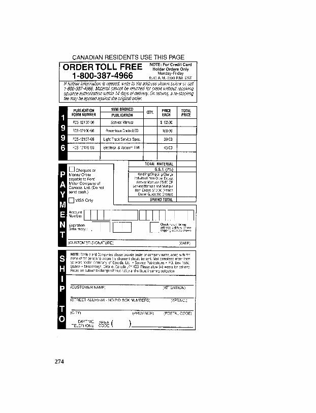
274
[AC03000(B )02/95]
thirty-six pica chart:0021247-B
File:ltacb.exUpdate:Fri Jun 9 15:24:54 1995

275
Servicing Your Bronco
%*[SV00300( ALL)03/95] Service Made Easy
*[SV00400(BEF )01/95] Ford has two goals for servicing your vehicle.
*[SV00500(BEF )01/95] 1. When we can, we design parts that do notneed to be serviced.
*[SV00600(BEF )01/95] 2. We want to make servicing your vehicle aseasy as possible. To help you:
*[SV00700(BEF )01/95] ❑We highlight do-it-yourself items in yellow inthe engine compartment so that you can findthem easily.
*[SV00800(BEF )01/95] ❑When possible, we design parts — such asthe headlamp bulbs — that can be replacedwithout tools.
*[SV00900(BEF )05/94] ❑We give you a Maintenance Schedule thatmakes tracking routine service for yourvehicle easy. The maintenance schedule islocated in the Maintenance Schedule and Recordbooklet.
*[SV01000( ALL)01/95] This chapter tells you about the basic parts thatyou need to check and service regularly.
*[SV01100( ALL)02/95] If your vehicle needs professional servicing, yourdealership can provide the parts and servicerequired. Check your Warranty Information Bookletto find out which parts and services are covered.Also see the Customer Assistance chapter of thisOwner Guide.
File:ltsvb.exUpdate:Tue Jun 20 16:56:22 1995

276
*[SV01300( ALL)03/95] Ford Motor Company recommends that theOwner Maintenance Checks listed in theMaintenance Schedule and Record booklet beperformed for the proper operation of yourvehicle. In addition to the conditions listed inthe Owner Maintenance Checklist, be alert for anyunusual noise, vibration, or other indication thatyour vehicle may need service. If you do noticesomething unusual, see that your vehicle isserviced promptly.
*[SV01600(BEF )03/95] Precautions When Servicing YourVehicle
*[SV01700(BEF )01/95] Be especially careful when inspecting orservicing your vehicle. Here are some generalprecautions for your safety:
*[SV01900( ALL)03/95] ❑ If you must work with the engine running,avoid wearing loose clothing or jewelry thatcould get caught in moving parts. Takeappropriate precautions with long hair.
*[SV02000(BEF )01/95] ❑Do not work on a vehicle in an enclosedspace with the engine running, unless you aresure you have enough ventilation.
*[SV02100(BEF )01/95] ❑Never get under a vehicle while it issupported by a jack only. If you must workunder a vehicle, use safety stands.
*[SV02200(BEF )01/95] ❑Keep all lit cigarettes and other smokingmaterials away from the battery and allfuel-related parts.
*[SV02500( ALL)03/95] If you disconnect the battery, the engine must“relearn” its idle conditions before your vehiclewill drive properly. To find out how the enginedoes this, see Battery in this chapter.
File:ltsvb.exUpdate:Tue Jun 20 16:56:22 1995

277
*[SV02600( ALL)03/95] Working with the engine off:
*[SV02660(B F )05/95] 1. Always set the parking brake fully and makesure that the gearshift is securely latched inP (Park) (automatic transmission) or in 1(First) (manual transmission).
*[SV02675(B F )01/95] 2. When the transfer case is in the N (Neutral)position, the engine and transmission aredisconnected from the rest of the driveline.Therefore, the vehicle is free to roll even ifthe automatic transmission is in P (Park) orthe manual transmission is in gear. Do notleave the vehicle unattended with thetransfer case in the N (Neutral) position.
*[SV02700( ALL)03/95] 3. Remove the key from the ignition after youturn the engine off.
*[SV02725( ALL)03/95] 4. Block the wheels. This will prevent yourvehicle from moving unexpectedly.
*[SV02750( ALL)03/95] Working with the engine on:
*[SV02660(B F )05/95] 1. Always set the parking brake fully and makesure that the gearshift is securely latched inP (Park) (automatic transmission) or in 1(First) (manual transmission).
*[SV02800(B F )01/95] 2. When the transfer case is in the N (Neutral)position, the engine and transmission aredisconnected from the rest of the driveline.Therefore, the vehicle is free to roll even ifthe automatic transmission is in P (Park) orthe manual transmission is in gear. Do notleave the vehicle unattended with thetransfer case in the N (Neutral) position.
*[SV02900( ALL)02/95] RWARNING
Do not start your engine with the aircleaner removed and do not remove itwhile the engine is running.
File:ltsvb.exUpdate:Tue Jun 20 16:56:22 1995

278
*[SV02950(BEF )03/95] Opening the Hood
*[SV03000(B F )12/91] 1. Pull the hood release handle, located next tothe parking brake pedal.
*[SV03050(BEF )12/91] 2. While applying downward pressure on thehood, push the hood latch handle locatedbehind the grille near the center front of thevehicle to the left.
*[SV03150(B F )01/89] 3. As you open the hood to its fullest extent, aclock spring will assist you and “snap” intoposition. The clock spring lift secures thehood at its fullest height.
*[SV03300(BEF )03/91]
one third page art:0020333-A
Hood release handle
File:ltsvb.exUpdate:Tue Jun 20 16:56:22 1995

279
*[SV03600(B F )06/93]
half page art:0020337-E
Hood and support
*[SV03775(B F )12/89] NOTE: Be sure to oil the hood latch every sixmonths to maintain smooth operation.
*[SV03900(BEF )05/90] Always attempt to lift the hood after closing tobe sure it is securely latched.
%*[SV04500(BEF )04/95] Engine Compartment
*[SV04600(BEF )05/94] Your vehicle has one of the following types ofengines:
*[SV04750(BEF )05/89] ❑A 5.0 Liter EFI, V-8 engine, or
[SV04800(B )05/89] ❑A 5.8 Liter EFI, V-8 engine.
*[SV05500(BEF )11/94] The following pages show diagrams of eachengine type and where to find items that youshould regularly service.
File:ltsvb.exUpdate:Tue Jun 20 16:56:22 1995

280
*[SV05800(BF)04/95]
fullpageart:0020345-I
5.0L/5.8L
engin
ecom
partm
ent
servicep
oints
File:ltsvb.exU
pdate:T
ue Jun 20 16:56:22 1995

281
%*[SV05900(BEF )04/95] Cleaning the Engine
*[SV05920(BEF )04/95] A clean engine is more efficient because abuildup of grease and dirt acts as an insulator,keeping the engine warmer than usual.
*[SV05940(BEF )05/95] ❑Extreme care must be used if a power washeris used to clean the engine. The high pressurefluid could penetrate sealed parts andassemblies causing damage or malfunctions.
*[SV05960(BEF )04/95] ❑ In order to avoid possible cracking of theengine block or fuel injection pump, do notspray a hot engine or injection pump withcold water.
*[SV05980(BEF )04/95] ❑The alternator, distributor and air intake mustbe covered. Covering these components willhelp prevent water damage.
*[SV06000(BEF )04/95] ❑Never wash or rinse the engine while it isrunning. Water getting into the engine maycause internal damage.
*[SV06100( ALL)03/95] Filling the Fuel Tank[SV06300(B )01/89]
one third page art:0020348-A
Fuel filler door
File:ltsvb.exUpdate:Tue Jun 20 16:56:22 1995

282
*[SV06550(BEF )02/91] Opening the Fuel Filler Door
*[SV06600(BEF )10/94] To open the fuel filler door of your vehicle, justinsert your finger in the divot and pull the dooropen all the way.
*[SV06700( ALL)01/95] Removing the fuel cap
*[SV06750( ALL)01/95] The proper instructions for removing the fuelcap are as follows:
*[SV06800( ALL)03/90] ❑Unscrew the fuel cap by exerting pressure onthe plastic lock bar and rotating the fuel capcounterclockwise.
*[SV06850( ALL)12/91] ❑Turn the fuel cap 1/2 to 3/4 of a turn until ahissing sound is heard. Wait until the hissingsound stops and then continue rotatingcounterclockwise to remove the fuel cap.
*[SV06900( ALL)03/93] ❑Make sure that you follow the above fuel capremoval instructions and use caution. Suchcaution will minimize the possibility of fuelspraying during removal of the fuel cap.
*[SV06950( ALL)03/91] To replace and secure the fuel cap; place it inposition and rotate it clockwise until it clicks(ratchets). Doing so will not damage or breakthe fuel cap. The ratcheting mechanism allowsthe fuel cap to be sealed without overtightening.
[SV06975( ALL)05/95] If you lose the fuel cap, replace it with anauthorized Motorcraft or equivalent part.
%*[SV07000( ALL)05/95] RWARNING
If you do not use the proper fuel cap, thepressure in the fuel tank can damage thefuel system or cause it to work improperlyin a collision.
File:ltsvb.exUpdate:Tue Jun 20 16:56:22 1995

283
*[SV07025( ALL)05/95] NOTE: If you replace your fuel cap with anaftermarket fuel filler cap, the customerwarranty may be void for any damageto the fuel tank and/or fuel system.
*[SV07050( ALL)05/95] RWARNING
If the fuel cap is venting vapor or if youhear a hissing sound, wait until it stopsbefore completely removing the cap.
*[SV07060(BEF )11/89] A venting fuel tank is not an abnormalcondition. It may be caused by:
*[SV07061(BEF )03/90] ❑Too volatile a fuel for the weather conditions.The service stations sometimes sell wintergrade fuel in the summer.
*[SV07062(BEF )11/89] ❑Pulling a heavy load on hot days, or at highaltitudes.
*[SV07063(BEF )11/89] ❑Extended periods of idling with the engineRPM increased above the normal idle range.
*[SV07064(BEF )11/89] ❑Parking vehicle in full sunlight for extendedperiods on extremely hot days.
*[SV07500( ALL)05/95] Choosing the Right Fuel
*[SV07600( ALL)05/95] Use only UNLEADED FUEL in your vehicle.Using leaded fuel is prohibited by federal law.Your warranty may not apply if your vehicle isdamaged because you used the wrong fuel.
*[SV07700( ALL)05/95] Vehicle inspection programs may detectmisfueling. Under these circumstances, you maybe required by law to make costly repairs atyour own expense.
File:ltsvb.exUpdate:Tue Jun 20 16:56:22 1995

284
*[SV08710( ALL)04/95] Octane recommendations
*[SV08725( ALL)04/95] Your vehicle is designed to use regularunleaded fuel with an octane rating of 87. Inmost cases, it is not necessary to use a fuel withan octane rating higher than 87. At servicestations, the octane rating is displayed on a labelon the pumps.
*[SV08900( ALL)05/95]
one inch art:0060001-C
Typical octane rating label
*[SV09050( ALL)05/95] In some parts of the country, “regular” gradefuels are sold with octane ratings of 86 or evenless, especially in high altitude areas. Werecommend that you do not use these fuels.Always use a fuel with an octane rating of 87,even if it is sold as a “midgrade” or “premium.”
*[SV09200( ALL)05/95] Do not be concerned if your vehicle sometimesknocks lightly when you drive up a hill or whenyou accelerate. However, if a fuel with therecommended octane rating knocks heavilyunder all driving conditions or knocks lightlydriving at cruising speed on level roads, seeyour dealer or a qualified service technician.Persistent, heavy knocking can damage theengine.
*[SV09435( ALL)05/95] Fuel quality
*[SV09450( ALL)05/95] If you are experiencing starting, rough idle orhesitation problems when the engine is cold, itmay be caused by fuel with low volatility. Try adifferent brand of fuel. If the condition persists,see your dealer or a qualified service technician.
File:ltsvb.exUpdate:Tue Jun 20 16:56:22 1995

285
*[SV09452( ALL)05/95] Using a high-quality fuel makes your vehiclemore responsive and maintains its good fueleconomy and emissions by:
*[SV09455( ALL)05/95] ❑protecting your fuel system from rusting.
*[SV09460( ALL)05/95] ❑preventing the fuel lines from freezing.
*[SV09465( ALL)05/95] ❑ improving vehicle starting and warm-up.
*[SV09470( ALL)05/95] ❑protecting the fuel system from vapor lock invery hot weather, which causes the engine tohesitate or stall and makes restarts difficult.
*[SV09475( ALL)05/95] ❑minimizing deposits in fuel injectors,combustion chambers, and on intake valves.
*[SV09480( ALL)05/95] ❑preventing your fuel system from “gummingup” when your vehicle is not used for longperiods of time.
*[SV09485( ALL)05/95] ❑preventing your engine from knocking andpinging.
*[SV09500( ALL)05/95] It should not be necessary to add anyaftermarket products to your fuel tank if youcontinue to use a high-quality fuel.
*[SV09875( ALL)04/95] Gasolines for clean air
*[SV09900( ALL)05/95] Fuels in certain areas of the country are requiredto contain oxygenates to improve air quality.Common oxygenates are ethanol or grain alcohol(blended at no more than 10%), methanol orwood alcohol (blended at no more than 5% withcosolvents and additives), and MTBE or methyltertiary butyl ether (blended at no more than15%).
[SV09950( ALL)04/95] Reformulated gasoline is also required in certainareas of the U.S. These fuels are designed tofurther reduce the emissions from your vehicle.
File:ltsvb.exUpdate:Tue Jun 20 16:56:22 1995

286
[SV10000( ALL)04/95] Generally, you should not experience difficultiesoperating your vehicle on reformulated gasolineor on fuels containing oxygenates. We encourageyou to use these fuels.
%*[SV10185( ALL)05/95] Safety Information Relating to AutomotiveFuels
*[SV10195( ALL)05/95] RWARNING
Automotive fuels can cause serious injuryor death if misused or mishandled.
*[SV10200( ALL)05/95] Gasoline and other automotive fuels areextremely flammable. Turn your vehicle off anddo not smoke while refueling your vehicle. Keepsparks and other sources of ignition away fromfuels.
*[SV10205( ALL)03/95] Automotive fuels can be harmful or fatal ifswallowed. Further, gasoline may be blendedwith methanol. Even small amounts of methanolcan cause blindness and possibly death whenswallowed. Therefore, never attempt to siphonany fuel by mouth.
*[SV10210( ALL)03/95] If any fuel is swallowed, call a physician orpoison control center immediately. Do not delaycalling a physician merely because no adverseeffects are noticed at first; the toxic effects of agasoline-methanol blend, including blindness,may not become apparent for many hours. Ifgasoline is swallowed, do not induce vomiting.If a gasoline-methanol blend is swallowed,induce vomiting under the direction of aphysician or poison control center.
*[SV10215( ALL)03/95] Gasoline and gasoline-methanol blends maycontain small amounts of carcinogens, such asbenzene. Long-term exposure to unleadedgasoline vapors has caused cancer in laboratoryanimals. Further, excessive inhalation of fuelvapors can cause headache, dizziness, nausea,
File:ltsvb.exUpdate:Tue Jun 20 16:56:22 1995

287
loss of coordination, and other symptoms whichcould interfere with your ability to safelyoperate your vehicle. To the extent possible,avoid breathing vapors while refueling. If fuelvapors are inhaled in excessive quantities, movethe victim to fresh air and seek medicalattention.
*[SV10220( ALL)03/95] Fuels can also be harmful if absorbed throughthe skin. When refueling, be careful not tosplash fuel on yourself or your clothing. If fuelis splashed on the skin, promptly removecontaminated clothing and wash the skinthoroughly with soap and water.
*[SV10225( ALL)05/95] Fuels can cause severe eye irritation and possiblyeye damage. If fuel is splashed in the eyes,remove contact lenses (if worn), flush with largeamounts of water for 15 minutes, and seekmedical attention.
*[SV10230( ALL)05/95] You should be particularly careful if you aretaking the medication “Antabuse” or other formsof disulfiram for the treatment of alcoholism.There is a possibility that breathing the vaporsof a gasoline-methanol blend, or skin contactwith such a blend, may cause the same kind ofadverse reaction as drinking an alcoholicbeverage. In sensitive individuals, seriouspersonal injury or sickness could result. Consulta physician promptly if you experience anadverse reaction.
File:ltsvb.exUpdate:Tue Jun 20 16:56:22 1995

288
*[SV10300( ALL)02/95] Filling the fuel tank
*[SV10400( ALL)04/94] RWARNING
Do not overfill the fuel tank. The pressurein an overfilled tank may cause leakageand lead to fuel spray and fire.
*[SV10500( ALL)01/95] To fill the fuel tank properly:
*[SV10550( ALL)01/95] NOTE: Extinguish all lit cigarettes, othersmoking materials, and any openflames before fueling your vehicle.
*[SV10600( ALL)01/95] 1. Remove the fuel cap by following theinstructions above under Removing the FuelCap in this chapter. Proceed to add fuel tothe tank only if your vehicle is on levelground.
*[SV10700( ALL)03/95] 2. Make sure that you pump unleaded fuel andput the nozzle all the way inside the fuelfiller pipe.
*[SV10800( ALL)05/95] 3. If you spill any fuel on the body of yourvehicle, clean it off immediately. The fuelmay dull or soften the paint if you do notwash it off.
%*[SV10900( ALL)05/95] 4. Replace the fuel cap completely when youare finished. Turn it clockwise 1/4 turn untilit is tight. It will click when it is fullytightened.
%*[SV11300( ALL)05/95] Running Out of Fuel
*[SV11400( ALL)05/95] If your vehicle runs out of fuel, try to stop onlevel ground away from traffic. Add at least twogallons (8 liters) of fuel to start your vehicleagain. If your vehicle is not on level ground,you may need as much as five gallons (20 liters)of fuel to start it.
File:ltsvb.exUpdate:Tue Jun 20 16:56:22 1995

289
*[SV11500( ALL)05/95] You may need to crank the engine several timesbefore the fuel system starts to pump fuel fromthe tank to the engine.
%*[SV11600( ALL)05/95] Fuel Economy
*[SV11700( ALL)05/95] Fuel economy is an estimate of the efficiency ofyour vehicle and can be calculated as Miles PerGallon (MPG) or Liters Per 100 Kilometers(L/100K).
*[SV11750( ALL)05/95] Do not calculate fuel economy during yourvehicle’s break-in period. This would not be anaccurate estimate of how much fuel your vehiclewill normally use.
*[SV11800( ALL)05/95] To calculate fuel economy:
*[SV11900( ALL)05/95] 1. Fill the tank completely and record the initalodometer reading.
*[SV12000( ALL)05/95] 2. Every time you buy fuel record theamount (in gallons or liters) purchased.
*[SV12200( ALL)05/95] 3. After at least three to five tankfuls, fill thefuel tank and record the final odometerreading.
*[SV12225( ALL)05/95] 4. Use these equations to calculate your fueleconomy.
*[SV12250( ALL)05/95] ❑English: MPG = (total miles)/(gallons used).
*[SV12275( ALL)05/95] ❑Metric: L/100K = (liters used) x 100/(totalkilometers)
*[SV12300(BEF )05/95] Comparisons With EPA Fuel EconomyEstimates
*[SV12400(BEF )05/95] EPA fuel economy figures are obtained fromlaboratory tests under simulated road conditionsand may not reflect the actual conditions youexperience or your style of driving. The EPAfuel economy estimate is not a guarantee thatyou will achieve the fuel economy shown.
File:ltsvb.exUpdate:Tue Jun 20 16:56:22 1995

290
*[SV12500( ALL)05/95] Improving Fuel Economy
*[SV12600( ALL)05/95] Fuel economy is affected by a number ofvariables which can reduce efficiency. You canimprove fuel economy by understanding thesevariables and minimizing their effect.
*[SV12700( ALL)05/95] The following decrease fuel economy:
*[SV12800( ALL)05/95] ❑Lack of regular, scheduled maintenance
*[SV12900( ALL)05/95] ❑Driving with your foot on the brake
*[SV13000( ALL)05/95] ❑Sudden stops
*[SV13100( ALL)05/95] ❑Excessive speed
*[SV13200( ALL)05/95] ❑Extended engine idling
*[SV13300( ALL)05/95] ❑Heavy loads
*[SV13400( ALL)05/95] ❑Underinflated tires
*[SV13500(BEF )05/95] ❑Extended use of the A/C, defroster, rearwindow defroster and other accessories
*[SV13550(BEF )05/95] ❑Aftermarket add-ons such as bike, ski orluggage racks, bug deflectors, etc.
*[SV13600( ALL)02/95] Engine Oil Recommendations
*[SV13610( ALL)04/95] We recommend using Motorcraft oil or anequivalent oil meeting Ford SpecificationESE-M2C153-E and displaying the AmericanPetroleum Institute CERTIFICATION MARK onthe front of the container.
File:ltsvb.exUpdate:Tue Jun 20 16:56:22 1995

291
*[SV13655( ALL)03/95]
one third page art:0060020-D
The API Certification Mark
*[SV13670( ALL)01/95] Never use:
*[SV13680( ALL)01/95] ❑“Non-Detergent” oils
*[SV13690( ALL)04/95] ❑Oils labeled API SA, SB, SC, SD, SE, SF or SG
%*[SV13700( ALL)01/95] ❑Additional engine oil additives, oil treatmentsor engine treatments
[SV13701(B )06/95] For vehicles with 5.8L engines
*[SV13710(BEF )03/95] Engine oils with an SAE 5W-30 viscosity arePREFERRED for your vehicle. They provide thebest engine performance, fuel economy andengine protection for all climates down to -15˚F(-25˚C).
%*[SV13725( ALL)03/95] Synthetic engine oils which are CERTIFIED andof the preferred viscosity may be used in yourengine. The engine oil and oil filter must still bechanged according to the maintenance schedule.
[SV13735(B )03/95] For vehicles with 5.0L engines
[SV13740( ALL)04/95] Engine oils with an SAE 10W-30 viscosity arePREFERRED for your vehicle which provide thebest engine protection for all climates down to-5˚F (-20˚C). SAE 5W-30 engine oils may also beused down to -15˚F (-25˚C).
File:ltsvb.exUpdate:Tue Jun 20 16:56:22 1995

292
[SV13745( ALL)02/95] Synthetic engine oils which are CERTIFIED andof the preferred viscosity may be used in yourengine. The engine oil and oil filter must still bechanged according to the maintenance schedule.
*[SV13775( ALL)01/95] Checking and Adding Engine Oil
*[SV13800( ALL)03/95] Since the proper amount of engine oil isimportant for safe engine operation, check the oilusing the dipstick each time you put fuel inyour vehicle. Remember the engine must be off,the oil must be warm and the vehicle must beparked on level ground.
*[SV13900( ALL)03/95] Checking the engine oil level:
*[SV14000( ALL)02/95] 1. Turn the engine off after it has warmed upand allow a few minutes for the engine oilto drain back into the oil pan.
*[SV14050(B F )03/95] 2. Set the parking brake, making sure that thegearshift is securely latched in P (Park)(automatic transmission) or 1 (First) (manualtransmission).
*[SV14100( ALL)02/95] 3. Open the hood. Protect yourself from engineheat.
*[SV14200( ALL)03/95] 4. Locate the engine oil dipstick (highlighted inyellow) and carefully pull it out of theengine.
*[SV14300( ALL)01/95] 5. Wipe the dipstick clean and put it back intoposition, making sure it is fully seated.
*[SV14400( ALL)05/94]
quarter page art:0010364-D
Engine oil dipstick
File:ltsvb.exUpdate:Tue Jun 20 16:56:22 1995

293
*[SV14500( ALL)02/95] 6. Carefully, pull the dipstick out again. If theoil level is below the “ADD 1 QT.” line, addengine oil as necessary. If the oil level isbeyond the letter “F” in FULL, enginedamage or high oil consumption may occurand some oil must be removed from theengine.
*[SV14600( ALL)01/95] 7. Put the dipstick back in and make sure it isfully seated.
*[SV14800( ALL)01/95] It may be necessary to add some oil between oilchanges. Make sure you use a CERTIFIEDengine oil of the preferred viscosity. Yourvehicle’s warranty coverage may not apply ifengine damage is caused by the use of improperengine oil.
*[SV15000( ALL)03/95] Add engine oil through the oil filler caphighlighted in yellow. To add oil, remove thefiller cap and use a funnel to pour oil into theopening. Be careful not to overfill the engine.Recheck the oil level after you finish adding oil.
*[SV16500( ALL)04/95] Change the engine oil and oil filter per thefollowing, whichever occurs first.
*[SV16600(BEF )04/95]
one third page art:0060618-C
Oil change intervals
File:ltsvb.exUpdate:Tue Jun 20 16:56:22 1995

294
*[SV16625( ALL)03/95] NOTE: Idling the engine for extended periodswill accumulate more hours of use onyour vehicles than is actually indicatedby the mileage odometer.Consequently, the odometer readingcan be often misleading whendetermining the right time to changeyour engine oil and filter.
*[SV16650(BEF )03/95] If you are using your Ford vehicle in a mannerwhich allows it to remain stationary while theengine is running for long periods (door to doordelivery, taxi, police, power/utility companytrucks, or similar duty), then Ford recommendsyou increase the frequency of oil and filterchanges to an interval equivalent to 200ENGINE HOURS of use. Since most vehicles arenot equipped with hourmeters, it may benecessary for you to approximate your idle timeand plan oil/filter changes accordingly.
*[SV16800( ALL)04/95] Refer to the Maintenance Schedule and Recordbooklet for additional information.
%*[SV17250( ALL)04/95] NOTE: Always dispose of used automotivefluids in a responsible manner. Followyour community’s standards fordisposing of these types of fluids. Callyour local recycling center to find outabout recycling automotive fluids.
*[SV17275( ALL)05/95] RWARNING
Continuous contact with USED motor oilhas caused cancer in laboratory mice.
*[SV17280( ALL)05/95] Protect your skin by washing with soap andwater.
File:ltsvb.exUpdate:Tue Jun 20 16:56:22 1995

295
*[SV17300( ALL)03/95] Engine Coolant
*[SV17400( ALL)02/95] Checking the engine coolant
*[SV17700( ALL)10/89] Your vehicle’s engine coolant protects the enginefrom overheating in the summer and fromfreezing in the winter. Check the level of theengine coolant at least once a month, butpreferably each time you stop for fuel. Simplylook at the engine coolant recovery reservoirlocated in the engine compartment. To locatethis reservoir, see the diagram of your vehicle’sengine under Engine types in this chapter.
*[SV17750( ALL)03/95] If the engine coolant has not been checked for along period of time the engine coolant reservoirmay eventually empty. If the engine coolantreservoir empties, check the engine coolant levelin the radiator. Read the following warningsbefore removing the radiator cap. If it isnecessary to fill the radiator, refer to the EngineCoolant Refill Procedure in this chapter forinstructions.
*[SV17950(BEF )01/95] Adding engine coolant
*[SV18000(B F )07/94]
quarter page art:0020354-A
Adding engine coolant
File:ltsvb.exUpdate:Tue Jun 20 16:56:22 1995
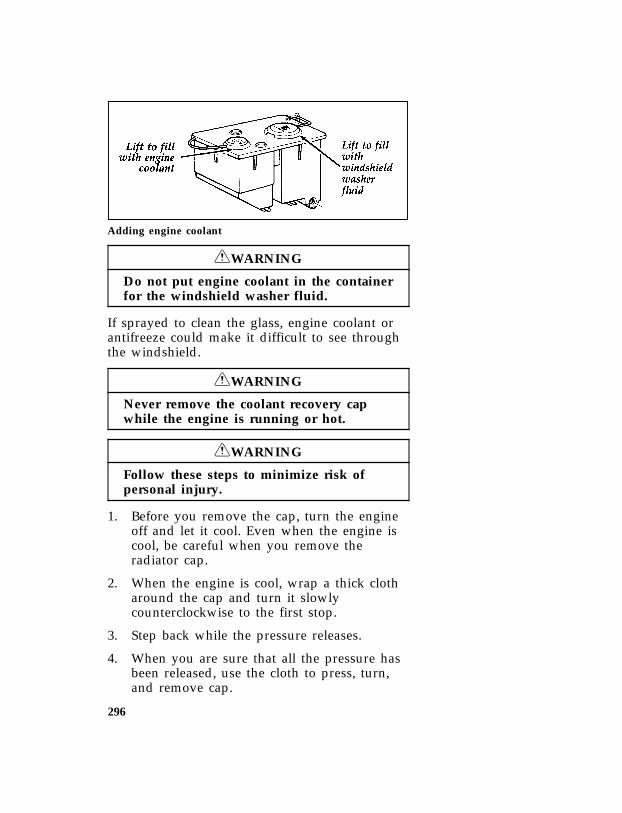
296
*[SV18150(B F )05/90]
quarter page art:0020360-C
Adding engine coolant
*[SV18400( ALL)05/95] RWARNING
Do not put engine coolant in the containerfor the windshield washer fluid.
*[SV18420( ALL)05/95] If sprayed to clean the glass, engine coolant orantifreeze could make it difficult to see throughthe windshield.
*[SV18500( ALL)05/95] RWARNING
Never remove the coolant recovery capwhile the engine is running or hot.
*[SV18600( ALL)05/95] RWARNING
Follow these steps to minimize risk ofpersonal injury.
*[SV18700( ALL)03/95] 1. Before you remove the cap, turn the engineoff and let it cool. Even when the engine iscool, be careful when you remove theradiator cap.
*[SV18800( ALL)03/95] 2. When the engine is cool, wrap a thick clotharound the cap and turn it slowlycounterclockwise to the first stop.
*[SV18900( ALL)03/95] 3. Step back while the pressure releases.
*[SV19000( ALL)04/95] 4. When you are sure that all the pressure hasbeen released, use the cloth to press, turn,and remove cap.
File:ltsvb.exUpdate:Tue Jun 20 16:56:22 1995

297
*[SV19100( ALL)03/95] 5. Stand away from the radiator opening. Hotsteam may blow out or hot engine coolantmay even splash out.
*[SV19500( ALL)01/93] Freezing Protection
*[SV19600( ALL)03/91] The factory-installed solution of Ford PremiumCooling System Fluid and water will protectyour vehicle to s35˚F (s37˚C). Check the freezeprotection rating of the engine coolant at leastonce a year, just before winter.
*[SV19701( ALL)02/95] Add engine coolant only to the recoveryreservoir. If the coolant level is low, add to thereservoir a 50/50 mixture of water and the typeof engine coolant that Ford specifies. You mayadd water by itself only in an emergency, butyou should replace it with a 50/50 mixture assoon as possible.
*[SV19801( ALL)02/95] Ford Premium Cooling System Fluid is anoptimized formula that will protect all metalsand rubber elastomers used in Ford engines forfour years or 50,000 miles (80,000 km). It is notnecessary and not recommended to usesupplemental coolant additives in your gasolinepowered vehicle. These additives may harmyour engine cooling system. Follow therecommended service interval for changing yourengine coolant.
*[SV19851( ALL)04/94] NOTE: When you change or add enginecoolant, it is important to maintainyour engine coolant concentrationbetween 40% (-11˚F [-24˚C]) and 60%(-62˚F [-52˚C]), depending on your localclimate conditions. Below 40% you willlose freeze protection and above 60%your engine may overheat on a warmday.
File:ltsvb.exUpdate:Tue Jun 20 16:56:22 1995

298
*[SV19950( ALL)03/95] NOTE: Do not use an engine coolant that doesnot meet all 14 requirements of FordSpecification ESE-M97B44-A. The useof an improper coolant may void yourwarranty for the engine cooling system.Use only a premium nationallyrecognized brand name engine coolant.
*[SV19960( ALL)05/95] Ford Motor Company expressly authorizes theFord Rotunda engine coolant recycling processand chemicals. Use only Ford Rotunda recycledengine coolant or an equivalent recycled enginecoolant that is certified by the supplier to meetFord specification ESE-M97B44-A.
%*[SV19980( ALL)04/95] NOTE: Always dispose of used automotivefluids in a responsible manner. Followyour community’s standards fordisposing of these types of fluids. Callyour local recycling center to find outabout recycling automotive fluids.
*[SV20001( ALL)01/95] Use Ford Premium Cooling System Fluid or anequivalent engine coolant that meets FordSpecification ESE-M97B44-A. Do not use alcoholor methanol antifreeze and do not use enginecoolant mixed with alcohol or methanolantifreeze. If you do not use the proper coolant,the aluminum radiator on your vehicle willcorrode.
*[SV20100( ALL)01/95] Leave the engine coolant in all year. Make surethat the coolant will not freeze at thetemperature level in which you drive duringwinter months. Keep a mixture of engine coolantin your engine that has a protection rating of atleast -34˚F (-37˚C), or whatever protection ratingis appropriate for the climate in which you live.
*[SV20125( ALL)03/95] To find out how much engine coolant mixtureyour vehicle’s coolant system can hold, see Refillcapacities for fluids in the Index.
File:ltsvb.exUpdate:Tue Jun 20 16:56:22 1995

299
*[SV20151( ALL)01/95] You may add water by itself only in anemergency, but you should replace it with a50/50 or appropriate mixture as soon aspossible.
*[SV20200( ALL)01/95] Have your dealer check the engine coolingsystem for leaks if you have to add a quart(liter) of engine coolant more than once a month.
%*[SV20500( ALL)11/94] Checking hoses
*[SV20600( ALL)10/89] Inspect all engine and heater system hoses fordeterioration, leaks and loose clamps beforeadding or replacing engine coolant. Makewhatever repairs or replacements that arenecessary using Motorcraft parts or theirequivalents.
*[SV20700( ALL)05/95] Engine coolant drain and flush
*[SV20800( ALL)10/89] To drain your vehicle’s engine coolant:
*[SV20900( ALL)03/94] 1. Turn off the engine and let it cool. Fullydepressurize the engine cooling system bycovering the radiator cap with a thick clothand turning it slowly counterclockwise to thefirst stop. Step back while the pressurereleases.
*[SV20950( ALL)05/90] 2. Remove the cap.
*[SV21000(B FM)05/90] 3. Attach a small hose to the drain tube at thebottom of the radiator.
*[SV21200( ALL)05/90] 4. Let the engine coolant drain into a suitablecontainer. Disconnect the lower radiator hoseat the radiator connector and drain anyremaining engine coolant into a container.
*[SV21225( ALL)05/94] 5. Reconnect the lower radiator hose and closethe radiator drain cock.
*[SV21250( ALL)10/94] Proper procedures for flushing the coolingsystem can be found in the Truck Service Manual.
File:ltsvb.exUpdate:Tue Jun 20 16:56:22 1995

300
*[SV21300( ALL)02/95] Engine coolant refill procedure
*[SV21400( ALL)10/89] After you have drained the engine coolingsystem:
*[SV21500( ALL)01/89] 1. Fill the radiator with a 50/50 mixture of thespecified engine coolant concentrate andwater. Allow several minutes for trapped airto escape (bubble out) and for engine coolantto flow through the radiator.
*[SV21900( ALL)03/94] 2. Replace the radiator cap to its fully installedposition, then back off to the first stop. Thiswill prevent high pressure from building upin the cooling system during this part of thefill procedure.
*[SV22100( ALL)10/89] 3. Start and idle the engine until the thermostatopens and the radiator upper hose becomeswarm.
*[SV22200( ALL)05/95] 4. Shut off the engine and allow the engine tocool. Cover the radiator cap with a thickcloth and cautiously remove it. Step backwhile the pressure releases.
*[SV22500( ALL)10/89] 5. Finally, check the radiator and add moreengine coolant if needed, following theprocedures noted above. Reinstall theradiator cap securely, when finished.
*[SV22525( ALL)05/90] 6. If more engine coolant is necessary, fill theoverflow reservoir to the appropriate levelmarked on the bottle.
File:ltsvb.exUpdate:Tue Jun 20 16:56:22 1995
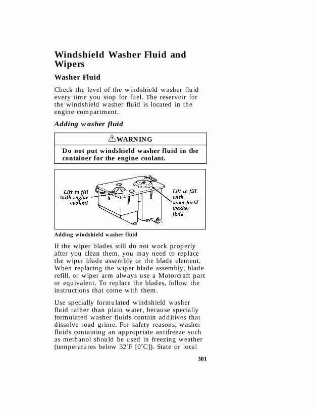
301
*[SV22700(BEF )03/95] Windshield Washer Fluid andWipers
*[SV22800(BEF )03/95] Washer Fluid
*[SV22900(BEF )01/95] Check the level of the windshield washer fluidevery time you stop for fuel. The reservoir forthe windshield washer fluid is located in theengine compartment.
*[SV23200(BEF )03/95] Adding washer fluid
*[SV23300(BEF )05/95] RWARNING
Do not put windshield washer fluid in thecontainer for the engine coolant.
*[SV23600(B F )02/92]
quarter page art:0020360-C
Adding windshield washer fluid
*[SV23700(B )03/95] If the wiper blades still do not work properlyafter you clean them, you may need to replacethe wiper blade assembly or the blade element.When replacing the wiper blade assembly, bladerefill, or wiper arm always use a Motorcraft partor equivalent. To replace the blades, follow theinstructions that come with them.
%*[SV23850(BEF )01/95] Use specially formulated windshield washerfluid rather than plain water, because speciallyformulated washer fluids contain additives thatdissolve road grime. For safety reasons, washerfluids containing an appropriate antifreeze suchas methanol should be used in freezing weather(temperatures below 32˚F [0˚C]). State or local
File:ltsvb.exUpdate:Tue Jun 20 16:56:22 1995

302
regulations on Volatile Organic Compounds(VOC’s) may restrict use of the most commonantifreeze, methanol. Washer fluids containingnon-methanol antifreeze agents should be usedonly if they provide cold weather protectionwithout damaging the vehicle’s paint finish,wiper blades, and windshield washer system.
*[SV23900(BEF )10/89] If you choose to use a windshield washingsolution that must be mixed, follow themanufacturer’s mixing instructions. Improperlymixed solutions may freeze unexpectedly.
[SV24000(BEF )04/95] NOTE: The addition of shields to the front ofthe vehicle, as used to deflect bugs,may also adversely affect the washersystem from delivering fluid to thewindshield. Devices such as bugshields are not recommended to beadded to your new Ford product.
%*[SV24500(BEF )03/95] Wiper Blades
*[SV24600(BEF )03/95] Check the windshield wiper blades at least twicea year. Also check them whenever they seemless effective than usual. Such substances as treesap and some hot wax treatments used bycommercial car washes reduce the effectivenessof wiper blades.
*[SV24700(BEF )03/95] If the blades do not wipe properly, clean boththe windshield and the wiper blades. Useundiluted windshield washer solution or a milddetergent. Rinse thoroughly with clear water. Donot use fuel, kerosene, paint thinner, or othersolvents to clean your wiper blades. These willdamage your blades.
*[SV24800(BEF )02/95] To make reaching the wiper blades easy, simplyturn the ignition switch to ACC and turn yourwipers on. Wait for them to reach a verticalposition and turn the ignition to OFF. Do notmove the wipers manually. Moving the wipersmanually may damage them.
File:ltsvb.exUpdate:Tue Jun 20 16:56:22 1995

303
*[SV24900(BEF )03/01] Wiper blade replacement
*[SV25000(BEF )03/95] If the wiper blades still do not work properlyafter you clean them, you may need to replacethe wiper blade assembly or the blade element.When replacing the wiper blade assembly, bladerefill, or wiper arm always use a Motorcraft partor equivalent. To replace the blades, follow theinstructions that come with them.
*[SV25200( ALL)03/95] Tires
*[SV25300( ALL)03/95] Look at your tires each time you fill your fueltank. If one tire looks lower than the others,check the pressure in all of them. Always followthese precautions:
*[SV25400( ALL)04/95] ❑Keep your tires inflated to the pressures thatare recommended. (See Checking the pressureof the tires later in this chapter.)
*[SV25500(BEF )02/95] ❑Stay within the recommended load limits (seeLoad limits in the Index).
*[SV25600( ALL)02/95] ❑Make sure the weight of your load is evenlydistributed.
*[SV25700( ALL)10/89] ❑Drive at safe speeds.
*[SV25800( ALL)01/95] If you do not take these precautions, your tiresmay fail or go flat.
*[SV25875( ALL)05/95] Ford Motor Company recommends obeyingposted speed limits.
*[SV25900( ALL)05/95] RWARNING
Driving too fast for conditions creates thepossibility of loss of vehicle control.Driving at very high speeds for extendedperiods of time may result in damage tovehicle components.
File:ltsvb.exUpdate:Tue Jun 20 16:56:22 1995

304
*[SV26000( ALL)03/95] Checking the pressure of the tires
*[SV26100( ALL)11/89] At least once a month, check the pressure in allyour vehicle’s tires, including the spare. Use anaccurate tire pressure gauge. Check the tirepressure when tires are cold, that is, after thevehicle has been parked for at least one hour orhas been driven less than 3 miles (5 km). Youcan find the proper cold pressure on the SafetyCompliance Certification Label.
*[SV26150( ALL)05/95] RWARNING
Improperly inflated tires can affect vehiclehandling and can fail suddenly, possiblyresulting in loss of vehicle control.
*[SV26200( ALL)02/95] Tire inspection and maintenance
*[SV26300( ALL)02/95] Inspect the tire treads, and remove stones, nails,glass or other objects that may be wedged in thetread grooves. Check for holes or cuts that maypermit air to leak from the tire, and make thenecessary repairs.
*[SV26400( ALL)10/89] Inspect the tire side walls for cuts, bruises andother damage. If you suspect internal damage tothe tire, have it demounted and checked. Youmay need to repair or replace it.
*[SV26410( ALL)11/89] Wheel inspection and maintenance
*[SV26420( ALL)11/89] Check for damage that would affect the runoutof the wheels. Wobble or shimmy will eventuallydamage the wheel bearings.
*[SV26430( ALL)06/93] Front wheel bearings require periodic repackingand adjustment as specified in the MaintenanceSchedule and Record booklet. Loose or worn frontwheel bearings tend to let the vehicle wander orshimmy, and can eventually cause excessive tirewear.
File:ltsvb.exUpdate:Tue Jun 20 16:56:22 1995

305
[SV26435( ALL)05/95] Whenever a wheel is removed and thenre-installed, always remove any corrosion thatmay be present on the mounting surface of thewheel and/or the surface of the hub, drum orrotor that contacts the wheel.
*[SV26440( ALL)05/95] RWARNING
Installing wheels without goodmetal-to-metal contact at the wheelmounting surface can cause the wheel lugnuts to loosen and could allow the wheelto come off while the vehicle is in motion.
*[SV26450(BEF )03/95] Traction-Lok Rear Axle (If equipped)
*[SV26460(BEF )03/95] This axle provides added drive away traction onslippery surfaces, particularly when one or morewheels are on a surface with poor traction.
*[SV26470(BEF )05/95] RWARNING
To avoid injury, never run the enginewith one wheel off the ground, such aswhen changing a tire.
%*[SV26500( ALL)02/95] Tire Rotation
*[SV26600( ALL)03/95] Because your vehicle’s front and rear tiresperform different jobs, they often weardifferently. To make sure your tires wear evenlyand last longer, rotate them at the mileageshown in the Maintenance Schedule and Recordbooklet which came with your vehicle.
*[SV26700(BEF )07/92] Rotate the tires according to the followingdiagram. If you notice that the tires wearunevenly, have them checked. If your light truckhas a temporary spare tire, do not include it inthe tire rotation pattern.
File:ltsvb.exUpdate:Tue Jun 20 16:56:22 1995

306
*[SV26750(BEF )03/90] In situations where the tires differ from front torear (snow/traction), simply rotate using a sideto side pattern.
*[SV26800(BEF )06/93]
half page art:0020364-A
Tire rotation pattern
*[SV26900(BEF )10/89] After each rotation, adjust individual tirepressure as specified on the Safety ComplianceCertification Label. Tighten wheel lug nuts to therequired torque specification and retighten againafter 500 miles (800 km).
*[SV27000(BEF )10/94] If your vehicle has aluminum wheels, you maydemount the full size, non-temporary sparetire (if so equipped) and remount on analuminum wheel to rotate the spare tire intoyour vehicle’s rotation pattern.
File:ltsvb.exUpdate:Tue Jun 20 16:56:22 1995
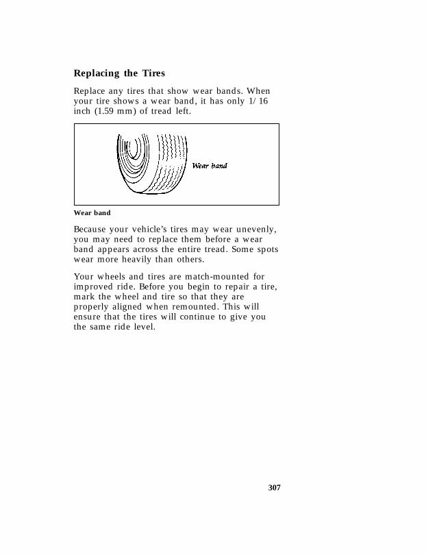
307
%*[SV27300( ALL)04/95] Replacing the Tires
*[SV27400( ALL)01/95] Replace any tires that show wear bands. Whenyour tire shows a wear band, it has only 1/16inch (1.59 mm) of tread left.
*[SV27500( ALL)10/89]
quarter page art:0060006-A
Wear band
*[SV27600( ALL)01/95] Because your vehicle’s tires may wear unevenly,you may need to replace them before a wearband appears across the entire tread. Some spotswear more heavily than others.
*[SV27700( ALL)03/90] Your wheels and tires are match-mounted forimproved ride. Before you begin to repair a tire,mark the wheel and tire so that they areproperly aligned when remounted. This willensure that the tires will continue to give youthe same ride level.
File:ltsvb.exUpdate:Tue Jun 20 16:56:22 1995

308
*[SV27851( ALL)01/95] RWARNING
When replacing full size tires, never mixradial, bias-belted, or bias-type tires. Useonly the tire sizes that are listed on thetire pressure decal. Make sure that all tiresare the same size, speed rating, andload-carrying capacity. Use only the tirecombinations recommended on the decal.If you do not follow these precautions,your vehicle may not drive properly andsafely.
*[SV27860( ALL)03/90] RWARNING
Make sure that all replacement tires are ofthe same size, type, load-carrying capacity,and tread design (e.g. “All Terrain”, etc.),as originally offered by Ford.
*[SV27885( ALL)04/95] RWARNING
Do not replace your tires with “highperformance” tires or larger size tires.
*[SV27895( ALL)05/95] RWARNING
Failure to follow these precautions mayadversely affect the handling of thevehicle and make it easier to lose controland roll over.
*[SV27900( ALL)01/95] Tires that are larger or smaller than yourvehicle’s original tires may also affect theaccuracy of your speedometer.
File:ltsvb.exUpdate:Tue Jun 20 16:56:22 1995

309
[SV28200(B )06/93]
full page art:0020367-E
Tire identification chart
File:ltsvb.exUpdate:Tue Jun 20 16:56:22 1995

310
*[SV28700(B )05/95] RWARNING
Use of aftermarket wheel assemblies maydamage your vehicle or cause accidentsresulting in serious injuries.
*[SV28800( ALL)04/95] Wheel and Tire Matching
*[SV28900( ALL)03/95] See an authorized tire dealer for properservicing procedures. Wheels and tires must beproperly removed, matched and remounted tomaintain the best possible ride.
%*[SV31100(BEF )04/95] Snow Tires and Chains
*[SV31200(BEF )01/95] The tires on your vehicle have all-weather treadsthat provide traction in rain or snow. However,during the winter months in some climates, youmay need to use snow tires and occasionallychains for your tires.
*[SV31300(BEF )05/95] RWARNING
Snow tires must be the same size andgrade as the tires you currently have onyour vehicle.
*[SV31400(BEF )02/95] Use chains on the tires only in an emergency orif the law requires them where you live. If youchoose to use chains on your vehicle’s tires, beaware of the following:
*[SV31500(BEF )01/95] ❑Make sure the chains are the right size foryour tires. Use only SAE Class “S” chains.Other types may damage your vehicle.
*[SV31600(BEF )01/95] ❑Put the chains on tightly with the ends helddown securely. Verify that no chain touchesany wiring, brake lines, or fuel lines. Followthe chain manufacturer’s instructions.
File:ltsvb.exUpdate:Tue Jun 20 16:56:22 1995

311
*[SV31700(BEF )01/95] ❑Drive slowly. If you can hear the chains rubor bang against your vehicle, stop the vehicleand tighten the chains. If you continue tohear the chains rub or bang against yourvehicle, remove the chains to prevent damageto your vehicle.
*[SV31800(BEF )10/94] ❑Avoid fully loading your vehicle if possible.
*[SV31900(BEF )05/94] ❑Remove tire chains at the first opportunityafter using them on snow and ice. Do not usethe chains on dry roads.
*[SV31950(BEF )05/91] ❑Make sure your suspension insulation andbumpers are not missing or worn to avoiddamage to your vehicle.
%*[SV31975(BEF )04/95] Cleaning the Wheels
*[SV31980(BEF )05/95] Wash the wheels with the same detergent youuse to wash your vehicle’s body. Do not useacid-based wheel cleaners, steel wool, abrasives,fuel, or strong detergents. These substances willdamage protective coatings. Use tar and road oilremover to remove grease and tar.
*[SV31985(BEF )04/95] NOTE: Before going to a car wash, find out ifthe brushes are abrasive.
*[SV32100( ALL)03/95] Battery*[SV32200( ALL)02/95] Your vehicle may have a Motorcraft
maintenance-free battery. When the originalequipment battery is replaced under warranty, itmay be replaced by a MotorcraftLow-Maintenance Battery.
*[SV32500( ALL)02/95] The Low-Maintenance Battery has removable ventcaps for checking the electrolyte level and foradding water, if necessary. The electrolyte levelshould be checked at least every 24 months or24,000 miles (40,000 km) in temperatures up to90˚F (32˚C) and more often in temperatures above90˚F (32˚C). Keep the electrolyte level in each cellup to the level indicator. Do not overfill.
File:ltsvb.exUpdate:Tue Jun 20 16:56:22 1995

312
*[SV32700( ALL)02/95] If the level gets low, you can add tap water tothe battery, provided the water isn’t hard ordoesn’t have a high mineral or alkali content.However, if possible you should refill the batterywith distilled water. If the battery needs waterquite often, have the charging system checkedfor a possible malfunction.
%*[SV32725( ALL)03/95] Help Us Protect Our Environment
*[SV32750( ALL)04/95] Ford Motor Company strongly recommends thatused lead-acid batteries be returned to anauthorized recycling facility for disposal.
*[SV32775( ALL)03/95]
one inch art:0000983-A
Battery recycling symbol
*[SV33200( ALL)01/95] RWARNING
Batteries normally produce explosive gaseswhich can cause personal injury.Therefore, do not allow flames, sparks orlit tobacco to come near the battery. Whencharging or working near a battery, alwayscover your face and protect your eyes, andalso provide ventilation.
%*[SV33300( ALL)05/95] RWARNING
Batteries contain sulfuric acid which burnsskin, eyes, and clothing.
File:ltsvb.exUpdate:Tue Jun 20 16:56:22 1995
313
*[SV33305( ALL)05/95] If the acid touches someone’s skin, eyes, orclothing, immediately flush the area with waterfor at least 15 minutes. If someone swallows theacid, have him or her drink lots of milk or waterfirst, then Milk of Magnesia, a beaten egg, orvegetable oil. Call a doctor immediately.
%*[SV33400( ALL)05/95] RWARNING
Applying too much pressure on the endswhen lifting a battery could cause acid tospill. Lift the battery with a carrier orwith your hands on the opposite corners.
*[SV33500( ALL)01/95] Automatic Transmission Fluid
*[SV33601( ALL)04/95] Under normal driving conditions automatictransmission fluid should be changed every30,000 miles (48,000 km) or 21,000 miles(34,000 km) if under severe duty conditions.However, if the transmission is not workingproperly, for instance, the transmission may slipor shift slowly, or you may notice some sign offluid leakage, the fluid level should be checked.
[SV33605( ALL)04/95] NOTE: Except E4OD transmission, there is no30,000 mile (48,000 km) sheduledtransmission fluid change requirement.
[SV33615( ALL)05/95] Transmission fluid, filter and seal assemblyshould be changed every 21,000 miles(34,000 km) only under any of the followingconditions.
[SV33620( ALL)04/95] ❑Extended periods of high speed drivingduring hot weather at/or above +90˚F(+30˚C).
[SV33625( ALL)04/95] ❑Towing a trailer for distances over 1,000 miles(1,600 km) per trip.
[SV33630( ALL)04/95] ❑Accumulating 5,000 miles (8,000 km) or moreper month.
File:ltsvb.exUpdate:Tue Jun 20 16:56:22 1995

314
[SV33635( ALL)04/95] ❑Continuous operation and/or extensive idling(a delivery service as an example).
[SV33640( ALL)04/95] ❑Operating in severe dust conditions.
[SV33645( ALL)04/95] NOTE: Use of a transmission fluid other thanspecified could result in transmissionmalfunction and/or failure. Refer to“Adding automatic transmission fluid”,“Refill capacities” and “lubricantspecifications” for further information.
%*[SV33651( ALL)02/95] Checking the Automatic TransmissionFluid
*[SV33701( ALL)02/95] It is preferable to check the transmission fluidlevel at normal operating temperature150˚F-170˚F (66˚C-77˚C), after approximately 20miles (32 km) of driving. However, if necessary,you can check the fluid level without having todrive 20 miles (32 km) to obtain a normaloperating temperature if outside temperaturesare above 50˚F (10˚C).
*[SV33801( ALL)01/95] NOTE: If the vehicle has been operated for anextended period at high speeds or incity traffic during hot weather, orpulling a trailer, the vehicle should beturned off for about 30 minutes toallow the fluid to cool before checking.
*[SV33910( ALL)12/91] With the vehicle on a level surface, start theengine and move the transmission shift selectorthrough all of the gear ranges allowing sufficienttime for each position to engage. Securely latchthe transmission shift selector in the Park (P)position, fully set the parking brake and leavethe engine running.
*[SV33920(B F )06/94] NOTE: Vehicles equipped with the 4x4 optionmust have the 4x4 shift selector in anyposition other than neutral.
File:ltsvb.exUpdate:Tue Jun 20 16:56:22 1995

315
*[SV33930( ALL)10/89] RWARNING
Your vehicle should not be driven if thefluid level is below the bottom hole onthe dipstick and outside temperatures areabove 50˚F (10˚C).
*[SV33940( ALL)02/95] Wipe off the dipstick cap, pull the dipstick outand wipe the indicator end clean. Put thedipstick back into the filler tube and make sureit is fully seated. Pull the dipstick out and readthe fluid level.
*[SV33950( ALL)03/90] When checking fluid at normal operatingtemperature, the fluid level should be within thecrosshatched area on the dipstick. When thevehicle has not been driven, and outsidetemperature is above 50˚F (10˚C), the fluid levelshould be between the holes on the dipstick.
%*[SV33960( ALL)05/95] Adding Automatic Transmission Fluid
*[SV33970( ALL)03/94] The fluid type is stamped on the dipstick. Beforeadding any fluid, be sure that the correct typewill be used.
*[SV33980( ALL)10/89] Add fluid in 1/2 pint (.25L) increments throughthe filler tube to bring the level to the correctarea on the dipstick. If an overfill occurs, excessfluid should be removed by a qualifiedtechnician.
%*[SV33990( ALL)04/95] NOTE: Always dispose of used automotivefluids in a responsible manner. Followyour community’s standards fordisposing of these types of fluids. Callyour local recycling center to find outabout recycling automotive fluids.
File:ltsvb.exUpdate:Tue Jun 20 16:56:22 1995
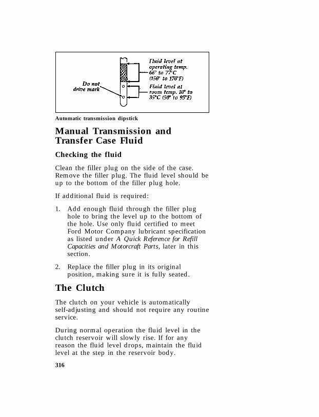
316
*[SV34000(B FM)06/92]
quarter page art:0020372-E
Automatic transmission dipstick
[SV34400(B F )01/95] Manual Transmission andTransfer Case Fluid
[SV34600(B F )01/95] Checking the fluid
*[SV34700(B F )12/91] Clean the filler plug on the side of the case.Remove the filler plug. The fluid level should beup to the bottom of the filler plug hole.
*[SV34800(B F )03/91] If additional fluid is required:
[SV34900(B F )01/95] 1. Add enough fluid through the filler plughole to bring the level up to the bottom ofthe hole. Use only fluid certified to meetFord Motor Company lubricant specificationas listed under A Quick Reference for RefillCapacities and Motorcraft Parts, later in thissection.
*[SV35000(B F )03/91] 2. Replace the filler plug in its originalposition, making sure it is fully seated.
%*[SV35100(B F )02/95] The Clutch
*[SV35200(B F )03/91] The clutch on your vehicle is automaticallyself-adjusting and should not require any routineservice.
*[SV35301(B F )03/91] During normal operation the fluid level in theclutch reservoir will slowly rise. If for anyreason the fluid level drops, maintain the fluidlevel at the step in the reservoir body.
File:ltsvb.exUpdate:Tue Jun 20 16:56:22 1995

317
%*[SV35400(B F )03/94] If it becomes necessary to remove the reservoircap, thoroughly clean the reservoir cap beforeremoving it to prevent dirt or water fromentering the reservoir. Remove the internaldiaphragm and then add only a DOT 3 brakefluid such as Ford High Performance DOT 3Brake Fluid, meeting Ford specificationESA-M6C25-A.
*[SV35600(B F )03/90]
one third page art:0020377-A
Clutch fluid reservoir
*[SV35800( ALL)03/91] Driveline Universal Joint andSlip Yoke
*[SV36000(BEF )06/93] The universal joints that come standard withyour vehicle do not require lubrication. If youroriginal equipment universal joints are replacedwith universal joints equipped with greasefittings, lubrication will be necessary at theintervals shown in the Maintenance Schedule andRecord booklet.
*[SV36100(B F )06/93] Your vehicle may be equipped with a constantvelocity or double cardan joint at the transfercase end of the driveshaft. The front driveshaftdouble cardan joint may be fitted with a flushtype grease fitting that requires an adapter topermit proper lubrication. Lubricate the drivejoint according to the intervals shown in theMaintenance Schedule and Record booklet.
File:ltsvb.exUpdate:Tue Jun 20 16:56:22 1995

318
*[SV36200(B F )05/90]
quarter page art:0020379-A
Double cardan joint
*[SV36300( ALL)03/95] Brake Fluid
*[SV36350( ALL)05/90] Your vehicle is equipped with a brake fluid levelindicator in the master cylinder which lights theBRAKE warning light on the instrument panelwhen the brake fluid level is low.
*[SV36400( ALL)04/95] Under normal circumstances, your vehicleshould not use up brake fluid rapidly. However,expect the level of the brake fluid to slowly fallas you put more mileage on your vehicle andthe brake lining wears.
*[SV36500( ALL)10/89] Check the brake fluid at least once a year. Youcan do this by looking at the fluid level in theplastic reservoir on the master cylinder. Thefluid level should be at or near the MAX mark.
*[SV36550( ALL)05/95] RWARNING
Brake fluid is toxic.
*[SV36560( ALL)05/95] If brake fluid contacts eyes, flush eyes withrunning water for 15 minutes. Get medicalattention if irritation persists. If taken internally,drink water and induce vomiting. Get medicalattention immediately.
File:ltsvb.exUpdate:Tue Jun 20 16:56:22 1995

319
*[SV36600( ALL)02/95] If the fluid is low, carefully clean and removethe filler cap from the reservoir. Fill thereservoir to the MAX line with Ford HighPerformance DOT 3 Brake Fluid C6AZ-19542-AAor DOT 3 equivalent fluid meeting Fordspecification ESA-M6C25-A.
*[SV36850( ALL)12/91] NOTE: If brake fluid is spilled on paintedsurfaces, it must be flushed and wipedaway immediately. Brake fluid maydissolve the paint finish on yourvehicle.
*[SV36900( ALL)01/95] RWARNING
If you use a brake fluid that is not DOT3, you will cause permanent damage toyour brakes.
*[SV37000( ALL)01/95] Do not fill the reservoir above the MAX line.
*[SV37100( ALL)01/95] If you find that the fluid level is excessively low— below the seam or ridge on the outside of theplastic reservoir — have the brake systeminspected.
*[SV37200( ALL)01/95] RWARNING
Do not let the reservoir for the mastercylinder run dry. This may cause thebrakes to fail.
*[SV37400(BEF )01/89]
quarter page art:0020381-A
Brake master cylinder
File:ltsvb.exUpdate:Tue Jun 20 16:56:22 1995

320
*[SV37600( ALL)03/95] Power Steering Fluid
*[SV37700( ALL)01/95] Check the level of the power steering fluid atleast twice a year (i.e., every Spring and Fall).
*[SV37800( ALL)03/95] To check the level of your power steering fluid:
*[SV37900( ALL)02/95] 1. Start the engine and let it run until thepower steering fluid reaches normaloperating temperature. The power steeringfluid will be at the right temperature whenthe engine coolant temperature gauge in theinstrument cluster is near the center of theNORMAL operating temperature range.
*[SV38000( ALL)01/95] 2. While the engine idles, turn the steeringwheel back and forth several times. Makesure that the cap assembly is installed at thistime.
*[SV38100(BEF )05/95] 3. Turn the engine off.
%*[SV38200( ALL)03/94] 4. Check the fluid level on the dipstick (whichis highlighted in yellow in your vehicle). Thefluid level should be between the arrows inthe FULL HOT range, which is marked onthe side of the dipstick, opposite the sidemarked FULL COLD. Do not add fluid if thelevel is within the FULL HOT range.
*[SV38250( ALL)03/94]
one third page art:0021016-B
Power steering dipstick
File:ltsvb.exUpdate:Tue Jun 20 16:56:22 1995

321
*[SV38600(B F )10/90]
quarter page art:0020386-B
Power steering reservoir
*[SV38800( ALL)07/94] 5. If the power steering fluid is low, add fluidin small amounts, continuously checking thelevel, until you reach the FULL HOT range.Do not overfill.
*[SV38900(BEF )01/95] Use only power steering fluid that:
*[SV39000(BEF )01/95] ❑meets Ford’s Specification ESW-M2C33-F,such as Ford Premium Power Steering Fluid,E6AZ-19582-AA or an equivalent Type FAutomatic Transmission Fluid with a Fordregistration number (an 8-digit numberbeginning with “2P” printed on the fluidcontainer).
*[SV39200( ALL)01/95] If the power steering fluid is low, do not driveyour vehicle for a long period of time beforeadding fluid. This can damage the powersteering pump.
*[SV39300( ALL)03/95] 6. When you are finished, put the dipstick backin and make sure that it fits snugly.
*[SV39400( ALL)02/95] If you check the power steering fluid when it iscold, make sure that the fluid reaches the FULLCOLD range on the dipstick. The reading willonly be accurate if the fluid temperature isapproximately 50 to 85˚F (10 to 30˚C).
File:ltsvb.exUpdate:Tue Jun 20 16:56:22 1995

322
*[SV39405( ALL)06/93] NOTE: Do not turn the steering wheel of yourvehicle with the engine off. It couldforce power steering fluid out from thereservoir cap or in extreme cases, itcould unseat the cap.
*[SV39500( ALL)04/95] Fuses, Fuse Links and CircuitBreakers
*[SV39650(B FM)12/91] Fuses, circuit breakers and fuse links protectyour vehicle’s electrical system from overloading.If electrical parts in your vehicle are notworking, the system may have been overloadedand blown a fuse or tripped a circuit breaker.Before you replace or repair any electrical parts,check the appropriate fuses or circuit breakers.
*[SV39700( ALL)10/89] The following charts tell you which fuses orcircuit breakers protect each electrical part ofyour vehicle. If a fuse blows or a circuit breakeropens a circuit, all the parts of your vehicle thatuse that circuit will not work.
*[SV39800( ALL)02/95] Once you have determined which fuses or circuitbreakers to check, follow the procedures underChecking and replacing fuses or Checking andreplacing circuit breakers later in this chapter.
File:ltsvb.exUpdate:Tue Jun 20 16:56:22 1995

323
*[SV40100(BF)03/94]
fullpageart:0020390-L
Fuses
and
their
location
File:ltsvb.exU
pdate:T
ue Jun 20 16:56:22 1995

324
[SV40120(B )05/95]
thirty-six pica chart:0020993-E
File:ltsvb.exUpdate:Tue Jun 20 16:56:22 1995
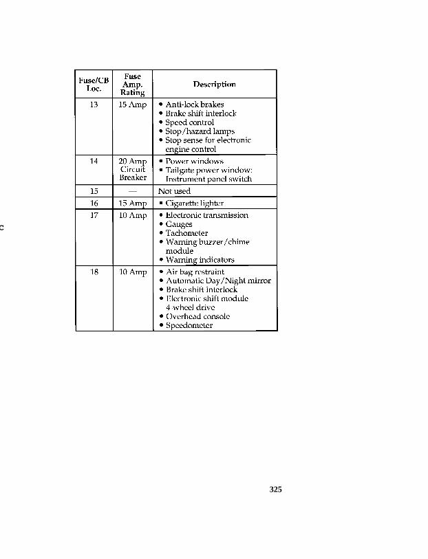
325
[SV40140(B )05/94]
twenty-eight pica chart:0020994-C
File:ltsvb.exUpdate:Tue Jun 20 16:56:22 1995

326
[SV40700(B )05/94]
twenty-two pica chart:0020396-F
*[SV41300( ALL)10/92] Power distribution box
*[SV41400( ALL)10/92] The high current fuses contained in the PowerDistribution Box protect your vehicle’s mainelectrical systems from overloads; these fusesprovide the connection between the battery andyour vehicle’s electrical systems.
*[SV41500( ALL)10/92] The high current fuses are coded as follows: 30amp -light green, 40 amp - orange, 50 amp - red,60 amp -blue.
File:ltsvb.exUpdate:Tue Jun 20 16:56:22 1995

327
*[SV41600( ALL)05/95] RWARNING
Always disconnect the battery beforeservicing high current fuses.
*[SV41620( ALL)05/95] Ford recommends that high current fuses bereplaced by a qualified technician.
*[SV41700( ALL)03/93] RWARNING
Always replace the cover to the PowerDistribution Box before reconnecting thebattery or refilling fluid reservoirs.
*[SV41800( ALL)04/95] A blown high current fuse may be replaced butwill continue to blow until the cause of theoverload condition is corrected.
*[SV41900( ALL)05/95] RWARNING
Always replace a fuse with one that hasthe specified amperage rating. Using afuse with a higher amperage rating cancause severe wire damage and could starta fire.
File:ltsvb.exUpdate:Tue Jun 20 16:56:22 1995

328
*[SV42150(B F )07/94]
three fourths page art:0020840-F
Power distribution box
File:ltsvb.exUpdate:Tue Jun 20 16:56:22 1995

329
[SV42153(B )04/95]
thirty-six pica chart:0021004-C
File:ltsvb.exUpdate:Tue Jun 20 16:56:22 1995

330
[SV42154(B )04/95]
twenty-eight pica chart:0021009-C
%*[SV42200( ALL)05/95] Checking and Replacing Fuses
*[SV42300( ALL)02/95] If you need to check a fuse, follow these steps:
*[SV42800(B F )03/91] 1. In order to find the fuse panel, you mustfirst remove the cover from the lower edgeof the instrument panel. You can do this bypulling on handle to disengage the fasteners.
File:ltsvb.exUpdate:Tue Jun 20 16:56:22 1995

331
*[SV42900(B F )03/91]
one third page art:0020475-B
Fuse panel cover
*[SV43300( ALL)10/94] 2. On the fuse panel cover, find the number ofthe fuse you want to check. The diagram onthe cover tells you where to locate the fuseon the panel.
*[SV43350(B FM)10/92] The underside of the cover also contains afuse pulling tool in case you need to replacea blown fuse.
*[SV43400( ALL)10/92] 3. Check the fuse to see if it is blown. Lookthrough the clear side of the fuse to see ifthe metal wire inside is separated. If it is,the fuse is blown and should be replaced.
*[SV43500( ALL)10/92]
quarter page art:0020405-A
The side view of a fuse
*[SV43600( ALL)10/92] 4. Replace the fuse with one that has the rightamperage rating (see previous chart).
File:ltsvb.exUpdate:Tue Jun 20 16:56:22 1995

332
*[SV43700( ALL)05/95] RWARNING
Always replace a fuse with one that hasthe specified amperage rating. Using afuse with a higher amperage rating cancause severe wire damage and could starta fire.
*[SV43800( ALL)10/92] 5. Put the fuse panel cover back on.
*[SV44000( ALL)05/93] Even after you replace a fuse, it will continue toblow if you do not find what caused theoverload. If the fuse continues to blow, haveyour electrical system checked.
%*[SV44100( ALL)03/95] Circuit Breakers
*[SV44200(BEF )03/95] If you need to check a circuit breaker on thefuse panel, see Checking and replacing fuses tofind out how to locate the fuse panel. Otherwise,locate the circuit breaker according to theinstructions on the charts given earlier in thischapter.
*[SV44300( ALL)02/95] Since you need diagnostic equipment to checkwhether a circuit breaker works and suchequipment comes with instructions, we do notdiscuss how to check circuit breakers.
*[SV44400( ALL)10/92] However, you should know that the circuitbreakers will reset themselves and allow theelectrical parts to work again once the overloadon the circuit is removed. If the circuit breakerscontinue to cut off electricity, have your vehicle’selectrical system checked.
*[SV44500( ALL)02/95] If you replace a circuit breaker, use one with thesame amperage rating. To remove a circuitbreaker mounted in the fuse panel, grip it withyour finger and thumb and pull it straight outof its socket.
File:ltsvb.exUpdate:Tue Jun 20 16:56:22 1995

333
%*[SV44600(BEF )03/95] Lights and Bulb Replacement
*[SV44700(BEF )01/95] It is a good idea to check the operation of thefollowing lights frequently:
*[SV44800(BEF )01/95] ❑headlamps
*[SV44900(BEF )01/95] ❑ tail lamps
*[SV45000(BEF )01/95] ❑brakelamps
*[SV45050(BEF )02/95] ❑high-mount brakelamp
*[SV45100(BEF )01/95] ❑hazard flasher
*[SV45200(BEF )01/95] ❑ turn signals
*[SV45300(BEF )01/95] ❑ license plate lamp
%*[SV45400(BEF )01/95] The alignment of your headlamps should bechecked if:
*[SV45500(BEF )01/95] ❑oncoming motorists frequently signal you toturn off your vehicle’s high beams when youdo not have the high beams on
*[SV45600(BEF )01/95] ❑ the headlamps do not seem to give youenough light to see clearly at night
*[SV45700(BEF )01/95] ❑ the headlamp beams are pointed substantiallyaway from a position slightly down and tothe right
File:ltsvb.exUpdate:Tue Jun 20 16:56:22 1995

334
*[SV45800(BEF )03/95] Headlamp Bulb
*[SV45900(BEF )01/95] The headlamps on your vehicle use replaceablebulbs. When the lamp burns out, simply replacethe bulb, rather than the whole lamp.
*[SV46000(BEF )05/95] RWARNING
Handle a halogen headlamp bulb carefullyand keep out of children’s reach. Graspthe bulb only by its plastic base and donot touch the glass. The oil from yourhand could cause the bulb to break thenext time the headlamps are operated.
*[SV46050(BEF )12/91] NOTE: If the bulb is accidently touched, itshould be cleaned with rubbingalcohol before being used.
*[SV46100(BEF )01/95] Do not remove the burned-out bulb unless youcan immediately replace it with a new one. If abulb is removed for an extended period of time,contaminants may enter the headlamp housingand affect its performance.
*[SV46200(BEF )03/91]
one third page art:0020406-B
Parts of a headlamp
File:ltsvb.exUpdate:Tue Jun 20 16:56:22 1995
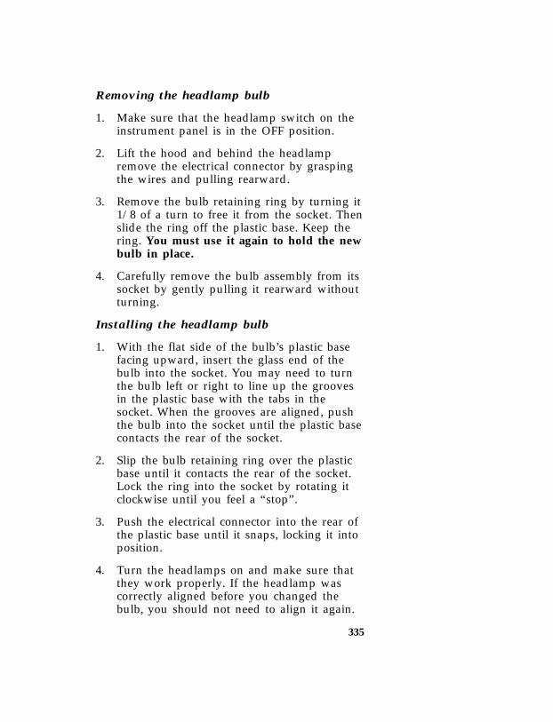
335
*[SV46300(BEF )03/95] Removing the headlamp bulb
*[SV46400(BEF )01/95] 1. Make sure that the headlamp switch on theinstrument panel is in the OFF position.
*[SV46501(B F )12/91] 2. Lift the hood and behind the headlampremove the electrical connector by graspingthe wires and pulling rearward.
*[SV46700(B F )04/95] 3. Remove the bulb retaining ring by turning it1/8 of a turn to free it from the socket. Thenslide the ring off the plastic base. Keep thering. You must use it again to hold the newbulb in place.
*[SV46800(B F )04/95] 4. Carefully remove the bulb assembly from itssocket by gently pulling it rearward withoutturning.
*[SV46900(BEF )03/95] Installing the headlamp bulb
*[SV47000(BEF )02/95] 1. With the flat side of the bulb’s plastic basefacing upward, insert the glass end of thebulb into the socket. You may need to turnthe bulb left or right to line up the groovesin the plastic base with the tabs in thesocket. When the grooves are aligned, pushthe bulb into the socket until the plastic basecontacts the rear of the socket.
*[SV47100(BEF )02/95] 2. Slip the bulb retaining ring over the plasticbase until it contacts the rear of the socket.Lock the ring into the socket by rotating itclockwise until you feel a “stop”.
*[SV47200(B F )02/95] 3. Push the electrical connector into the rear ofthe plastic base until it snaps, locking it intoposition.
*[SV47300(BEF )02/95] 4. Turn the headlamps on and make sure thatthey work properly. If the headlamp wascorrectly aligned before you changed thebulb, you should not need to align it again.
File:ltsvb.exUpdate:Tue Jun 20 16:56:22 1995

336
*[SV47310(B F )02/95] High-Mount Brakelamp Bulbs
*[SV47320(B F )03/95] To remove the brakelamp:
*[SV47330(B F )03/93] 1. Remove the two screws from the surface ofthe lens.
*[SV47340(B F )03/93] 2. After removing the screws, remove the lampassembly.
*[SV47350(B F )03/93] 3. Remove the socket by rotating it 45˚ andpulling it out of the lamp that contains theburned-out bulb and replace the bulb.
*[SV47360(B F )02/95] To install the high-mount brakelamp:
*[SV47365(B F )03/93] 1. Push the bulb socket into the lamp assemblyand rotate 45˚.
*[SV47370(B F )03/93] 2. Position the lamp assembly on vehicle.
*[SV47375(B F )03/93] 3. Secure with two screws.
*[SV47382(B F )07/93]
half page art:0020849-C
Replacing the high-mount brakelamp or cargo lamp bulb
File:ltsvb.exUpdate:Tue Jun 20 16:56:22 1995
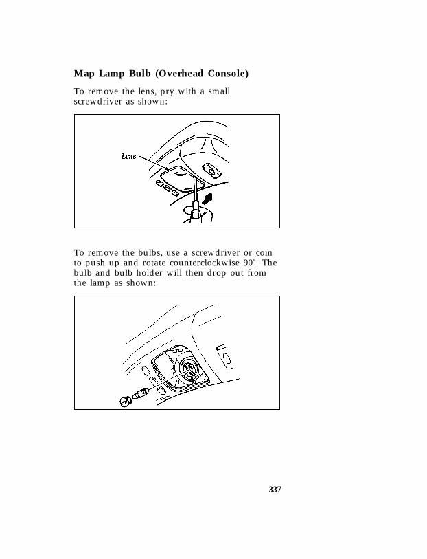
337
*[SV47401(B )02/95] Map Lamp Bulb (Overhead Console)
*[SV47402(B )03/93] To remove the lens, pry with a smallscrewdriver as shown:
[SV47403(B )03/93]
one third page art:0020977-A
*[SV47404(B )03/93] To remove the bulbs, use a screwdriver or cointo push up and rotate counterclockwise 90˚. Thebulb and bulb holder will then drop out fromthe lamp as shown:
[SV47405(B )03/93]
one third page art:0020978-A
File:ltsvb.exUpdate:Tue Jun 20 16:56:22 1995

338
%*[SV47625(BEF )02/95] Bulb specifications[SV47725(B )04/95]
thirty-six pica chart:0020409-I
File:ltsvb.exUpdate:Tue Jun 20 16:56:22 1995

339
[SV47750(B )03/91]
eight pica chart:0020791-A
%*[SV48600( ALL)03/95] Emission Control System
*[SV48700(BEF )05/95] Your vehicle is equipped with a catalyticconverter which enables your vehicle to complywith applicable exhaust emission requirements.
*[SV48725(B )05/95] RWARNING
Exhaust leaks may result in the entry ofharmful and potentially lethal fumes intothe passenger compartment. Underextreme conditions excessive exhausttemperatures could damage the fuelsystem, the interior floor covering, orother vehicle components, possiblycausing a fire.
*[SV48800(BEF )05/95] To make sure that the catalytic converter and theother emission control parts continue to workproperly:
*[SV48900( ALL)01/95] ❑Use only unleaded fuel.
*[SV49000( ALL)01/95] ❑Avoid running out of fuel.
*[SV49100( ALL)01/95] ❑Do not turn off the ignition while yourvehicle is moving, especially at high speeds.
*[SV49200( ALL)03/95] ❑Have the services listed in the MaintenanceSchedule and Record booklet performedaccording to the specified schedule. Thescheduled maintenance services are requiredbecause they are considered essential to thelife and performance of your vehicle and toits emissions system.
File:ltsvb.exUpdate:Tue Jun 20 16:56:22 1995

340
*[SV49250( ALL)03/95] In general, maintenance, replacement, or serviceof the emissions control devices or systems inyour new Ford Motor Company vehicle orengine may be performed at your expense byany automotive repair establishment orindividual using automotive parts equivalent tothose which your vehicle or engine wasoriginally equipped.
*[SV49300( ALL)05/95] RWARNING
Do not park, idle, or drive your vehicle indry grass or other dry ground cover. Theemission system heats up the enginecompartment and exhaust system, whichcan start a fire.
*[SV49400(BEF )05/95] RWARNING
On vehicles without original equipmentfloor covering or insulation, do not letpassengers ride in your truck in a mannerthat allows contact between skin and themetal floor.
*[SV49450( ALL)05/95] If other than Ford or Motorcraft or Fordauthorized remanufactured parts are used formaintenance, replacement, or for the service ofcomponents affecting emissions control, theowner should be assured that such parts arewarranted by their manufacturer to beequivalent to genuine Ford Motor Companyparts in performance and durability. Pleaseconsult your warranty information booklet forcomplete warranty information.
*[SV49500(BEF )05/95] Watch for fluid leaks, strange odors, smoke, lossof oil pressure, the charge warning light, thecheck engine light, or the temperature warninglight. These sometimes indicate that the emissionsystem is not working properly.
File:ltsvb.exUpdate:Tue Jun 20 16:56:22 1995
341
*[SV49600( ALL)01/95] Do not make any unauthorized changes to yourvehicle or engine. Changes that cause moreunburned fuel to reach the exhaust system canincrease the temperature of the engine orexhaust system.
*[SV49700( ALL)01/95] By law, anyone who manufactures, repairs,services, sells, leases, trades vehicles, orsupervises a fleet of vehicles is not permitted tointentionally remove an emission control deviceor prevent it from working. In some of theUnited States and in Canada, vehicle ownersmay be liable if their emission control device isremoved or is prevented from working.
*[SV49900( ALL)01/95] Do not drive your vehicle if it does not operateproperly. See your dealer if the engine runs onfor more than five seconds after you shut it offor if it misfires, surges, stalls, or backfires.
%*[SV50000( ALL)05/95] Information about your vehicle’s emissioncontrol system is on the Vehicle EmissionControl Information decal located on or near theengine. This decal identifies engine displacementand gives some tune-up specifications.
%*[SV51456( ALL)05/95] Readiness for Inspection/MaintenanceTesting
*[SV51457( ALL)05/95] In some localities it may become a legalrequirement to pass anInspection/Maintenance (I/M) test of theOn-Board Diagnostic (OBD) II system. If thevehicle’s powertrain system or its battery hasjust been serviced, the OBD II system is reset toa not ready for I/M testing condition. Toprepare for I/M testing, the law specifies a“need for additional mixed city and highwaydriving to complete the check” of the OBD IIsystem. As soon as all of the OBD II systemchecks are successfully completed, the OBD IIsystem is set to the ready condition. The amount
File:ltsvb.exUpdate:Tue Jun 20 16:56:22 1995

342
of driving required to reach the ready conditionvaries with individual driving patterns. Tocomplete this requirement in the minimumamount of time, refer to the OBD II Drive Cycledefined below. If the vehicle owner cannot ordoes not want to do the additional drivingrequired by law, a service center can performthis drive cycle as it would any other type ofrepair work.
[SV51458( ALL)05/95] OBD II Drive Cycle
[SV51459( ALL)04/95] The engine must be warmed up and atoperating temperature before proceeding withthe drive modes of the following OBD II DriveCycle.
[SV51461( ALL)04/95] 1. Start the engine. Drive or idle (in neutral)the vehicle for 4 minutes.
[SV51463( ALL)04/95] 2. Idle the vehicle in drive (neutral for manualtransmission) for 40 seconds.
*[SV51465( ALL)05/95] 3. Accelerate the vehicle to 45 mph (72 km/h)at 1/4 to 1/2 throttle for 10 seconds.
*[SV51467( ALL)05/95] 4. Drive the vehicle with a steady throttle at45 mph (72 km/h) for 30 seconds.
[SV51469( ALL)04/95] 5. Idle the vehicle in drive (neutral for manualtransmissions) for 40 seconds.
*[SV51471( ALL)05/95] 6. Continue to drive the vehicle in city traffic atspeeds between 25 and 40 mph(40-64 km/h) for 15 minutes. During the 15minute drive cycle the following modes mustbe achieved:
*[SV51473( ALL)05/95] a. at least 5 stop and idle modes at 10seconds each
*[SV51475( ALL)05/95] b. acceleration from idles at 1/4 to 1/2throttle position, and
*[SV51477( ALL)05/95] c. choose 3 different speeds to do 1.5minute steady state throttle drives.
File:ltsvb.exUpdate:Tue Jun 20 16:56:22 1995

343
*[SV51479( ALL)05/95] 7. Accelerate the vehicle up to between 45 and60 mph (72-97 km/h). This should takeapproximately 5 minutes.
*[SV51481( ALL)05/95] 8. Drive vehicle and hold the throttle steady atthe selected speed between 45 and 60 mph(72-97 km/h) for approximately 5 minutes.
*[SV51483( ALL)05/95] 9. Drive the vehicle for 5 minutes at varyingspeeds between 45 and 60 mph(72-97 km/h).
*[SV51485( ALL)05/95] 10. Bring the vehicle back to idle. Idle in drivefor 40 seconds.
*[SV51487( ALL)05/95] 11. OBD II drive cycle has been completed.Vehicle can be turned off when convenient.
File:ltsvb.exUpdate:Tue Jun 20 16:56:22 1995
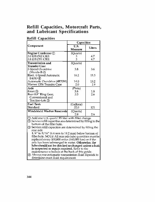
344
*[SV51500( ALL)03/95] Refill Capacities, Motorcraft Parts,and Lubricant Specifications
*[SV51600( ALL)03/95] Refill Capacities[SV51800(B )03/94]
thirty-four pica chart:0020418-K
File:ltsvb.exUpdate:Tue Jun 20 16:56:22 1995

345
[SV51900(B )03/94]
thirty-four pica chart:0020419-D
File:ltsvb.exUpdate:Tue Jun 20 16:56:22 1995

346
*[SV52800( ALL)01/95] Motorcraft Parts
[SV53000(B )05/95]
sixteen pica chart:0020429-M
File:ltsvb.exUpdate:Tue Jun 20 16:56:22 1995

347
*[SV53500(ALL)01/95]
Lu
brican
tsp
ecifications
[SV53900(B)05/95]
thirty-sixpicachart:0020437-G
File:ltsvb.exU
pdate:T
ue Jun 20 16:56:22 1995

348
[SV53950(B)04/95]
thirty-sixpicachart:0020508-H
File:ltsvb.exU
pdate:T
ue Jun 20 16:56:22 1995

349
[SV54000(B)05/95]
thirty-sixpicachart:0020438-M
File:ltsvb.exU
pdate:T
ue Jun 20 16:56:22 1995

350
[SV54100(B)04/95]
thirty-sixpicachart:0020439-L
File:ltsvb.exU
pdate:T
ue Jun 20 16:56:22 1995
351
%*[SV56000( ALL)01/95] Vehicle Storage
*[SV56100( ALL)01/95] Maintenance Tips
*[SV56150( ALL)01/95] If you plan on storing your vehicle for anextended period of time (60 days or more), referto the following maintenance recommendationsto ensure your vehicle stays in good operatingcondition.
*[SV56200( ALL)01/95] General
*[SV56300( ALL)01/95] ❑Store all vehicles in a dry, ventilated place.
*[SV56400( ALL)01/95] ❑Protect from sunlight, if possible.
*[SV56500( ALL)01/95] ❑ If vehicles are stored outside, they requireregular maintenance to protect against rustand damage.
*[SV56600( ALL)01/95] Body
*[SV56700( ALL)01/95] ❑Wash vehicle thoroughly to remove dirt,grease, oil, tar or mud from exterior surfaces,rear wheel housing and underside of frontfenders.
*[SV56800( ALL)01/95] ❑Periodically wash vehicles stored in exposedlocations.
*[SV56900( ALL)01/95] ❑Touch-up raw or primed metal to preventrust.
*[SV57000( ALL)01/95] ❑Cover chrome and stainless steel parts with athick coat of auto wax to preventdiscoloration. Re-wax as necessary when thevehicle is washed.
*[SV57100( ALL)04/95] ❑Lubricate all hood, door and trunk lid hingesand latches with a light grade oil.
*[SV57200( ALL)01/95] ❑Cover interior soft trim to prevent fading.
*[SV57300( ALL)01/95] ❑Keep all rubber parts free from oil andsolvents.
File:ltsvb.exUpdate:Tue Jun 20 16:56:22 1995

352
%*[SV57350( ALL)01/95] Engine
*[SV57400( ALL)01/95] ❑Start engine every 15 days. Run at fast idleuntil it reaches normal operating temperature.
*[SV57500( ALL)01/95] ❑With your foot on the brake, shift through allthe gears while the engine is running.
%*[SV57600( ALL)01/95] Fuel system
*[SV57700( ALL)07/94] ❑Fill fuel tank with high-quality unleaded fueluntil the first automatic shutoff of the fuelpump nozzle.
*[SV57900( ALL)03/95] NOTE: During extended periods of vehiclestorage (60 days or more), fuel maydeteriorate due to oxidation. This candamage rubber and other polymers inthe fuel system and may also clogsmall orifices.
*[SV58000( ALL)01/95] Ford Gas Stabilizer should be added wheneveractual or expected storage periods exceed 60days. Follow the instructions on the label. Thevehicle should then be operated at idle speed tocirculate the additive throughout the fuel system.
*[SV58100( ALL)01/95] A volatile corrosion inhibitor added to the fuelsystem will protect the fuel system’s innersurfaces from corrosion. Follow the instructionspackaged with the product.
%*[SV58200( ALL)01/95] Cooling system
*[SV58300( ALL)01/95] ❑Protect against freezing temperatures.
%*[SV58400( ALL)01/95] Battery
*[SV58500( ALL)01/95] ❑Check and recharge as necessary.
*[SV58600( ALL)01/95] ❑Keep connections clean and covered with alight coat of grease.
%*[SV58700( ALL)01/95] Brakes
*[SV58800( ALL)01/95] ❑Make sure brakes and parking brake are fullyreleased.
File:ltsvb.exUpdate:Tue Jun 20 16:56:22 1995

353
%*[SV58900( ALL)01/95] Tires
*[SV59000(B FM)05/95] ❑Maintain recommended air pressures.
*[SV59100( ALL)01/95] Miscellaneous
*[SV59200( ALL)01/95] ❑Make sure all linkages, cables, levers andclevis pins under vehicle are covered withgrease to prevent rust.
*[SV59300( ALL)03/95] ❑Move vehicles at least 25 feet (8 m) every 15days to lubricate working parts to preventcorrosion.
File:ltsvb.exUpdate:Tue Jun 20 16:56:22 1995

354
thirty-six pica chart:FORDADPLN
File:ltsvb.exUpdate:Tue Jun 20 16:56:22 1995

355
[QI02400(B )05/95]
full page art:0021504-B
Warning label locations
File:ltqib.exUpdate:Fri Jun 9 15:21:47 1995

356
[QI02700(B)06/93]
fullpageart:0021024-A
Front
exteriorview
File:ltqib.exU
pdate:Fri Jun 9 15:21:47 1995
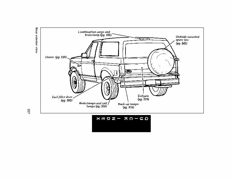
357
[QI03300(B)06/93]
fullpageart:0021030-A
Rear
exteriorview
File:ltqib.exU
pdate:Fri Jun 9 15:21:47 1995

358
[QI03900(B)05/94]
fullpageart:0021036-C
En
trance
view
File:ltqib.exU
pdate:Fri Jun 9 15:21:47 1995

359
[QI04500(B)06/93]
fullpageart:0021042-A
Driver’s
door
File:ltqib.exU
pdate:Fri Jun 9 15:21:47 1995

360
[QI05100(B)05/94]
fullpageart:0021048-D
Instru
men
tp
anel
File:ltqib.exU
pdate:Fri Jun 9 15:21:47 1995
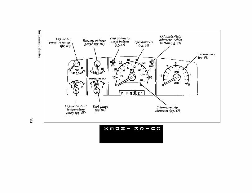
361
[QI05700(B)01/94]
fullpageart:0021054-B
Instru
men
tclu
ster
File:ltqib.exU
pdate:Fri Jun 9 15:21:47 1995

Index 363
Index
A
ABS warning light(see Anti-lock brake system) . . . . . . . 77
Accessory position on the ignition . . . . . 60Accessory power source,
power point outlet . . . . . . . . . . 148Additives, engine oil . . . . . . . . . . 291Air bag supplemental restraint system
description . . . . . . . . . . . . . . . 25disposal . . . . . . . . . . . . . . . . 32driver air bag . . . . . . . . . . . . . 25indicator light . . . . . . . . . . . . . 81operation . . . . . . . . . . . . . . . 27proper seating . . . . . . . . . . . . . 27service and information labels . . . . . . 32tone generator . . . . . . . . . . . . . 29wearing safety belts . . . . . . . . . . . 26
Air conditioning, manual heating and airconditioning system. . . . . . . . . . . 90
Alarm, activating remote personal . . . . 122Alcohol, in fuel . . . . . . . . . . . . . 285Ambulance packages . . . . . . . . . . . 5Antifreeze (see Engine coolant) . . . . . . 295Anti-lock brake system (ABS)
description . . . . . . . . . . . . . . 204noise . . . . . . . . . . . . . . . . 205see also Brake . . . . . . . . . . . . 203warning light. . . . . . . . . . . . . . 77
Assistance (see Customer assistance) . . . 255Audio system
(see Electronic sound system) . . . . . 149Automatic transmission, fluid, refill capacities 344Automatic transmission
driving an automatic overdrive . . . . 175fluid, adding . . . . . . . . . . . . . 315
File:ltixb.exUpdate:Fri Jun 9 15:21:14 1995

364 Index
Automatic transmission (continued)fluid, checking . . . . . . . . . . . . 314fluid, specification . . . . . . . . . . . 347
Axlelubricant specifications. . . . . . . . . 347traction lok . . . . . . . . . . . . 212, 305
BBacking up . . . . . . . . . . . . . . . 178Basic vehicle warranty . . . . . . . . . . . 4Battery
acid, treating emergencies . . . . . 237, 312battery saver . . . . . . . . . . . . . 125charging system warning light . . . . . . 81how to service . . . . . . . . . . . . 311jumping a disabled battery . . . . . . . 237maintenance-free . . . . . . . . . . . 311proper disposal, recycling . . . . . . . 312replacement, specifications . . . . . . . 346voltage gauge. . . . . . . . . . . . . . 82when storing your vehicle . . . . . . . 352
Brake fluidbrake warning light . . . . . . . . . . . 76specifications . . . . . . . . . . . . . 319
Brakelamp, high-mount brakelamp . . 101, 336Brakes
adjustment . . . . . . . . . . . . . . 203anti-lock . . . . . . . . . . . . . . . 204anti-lock brake system (ABS)
warning light. . . . . . . . . . . . . 77applying the brakes . . . . . . . . . . 207brake warning light . . . . . . . . . . . 76fluid, checking and adding. . . . . . . 318fluid, refill capacities . . . . . . . . . 344fluid, specifications . . . . . . . . . . 319front disc. . . . . . . . . . . . . . . 203if brakes do not grip well . . . . . . . 206new brake linings . . . . . . . . . . . . 7parking . . . . . . . . . . . . . . . 208stopping distances. . . . . . . . . . . 207
File:ltixb.exUpdate:Fri Jun 9 15:21:14 1995

Index 365
Brakes (continued)trailer . . . . . . . . . . . . . . . . 231when storing your vehicle . . . . . . . 352
Brake-shift interlock . . . . . . . . . . 66, 178Break-in period . . . . . . . . . . . . . . 7Bulbs, replacing
headlamps . . . . . . . . . . . . . . 334high-mount brakelamp . . . . . . . . 336
CCanada, customer assistance . . . . . . . 264Canadian Motor Vehicle Arbitration Plan
(CAMVAP). . . . . . . . . . . . . . 265Capacities for refilling fluids . . . . . . . 344Carbon monoxide in exhaust . . . . . . . . 71Car seats for children
(see Child safety seats) . . . . . . . . . 37Cassette tape player (see Electronic
sound system) . . . . . . . . . . 163, 168Catalytic converter . . . . . . . . . . . 339CD player (see Electronic sound system) . 156Chains, tires . . . . . . . . . . . . . . 310Changing a tire . . . . . . . . . . . . . 241Charging system gauge . . . . . . . . . . 82Charging system warning light . . . . . . . 81Child safety restraints . . . . . . . . . . . 34
child safety belts . . . . . . . . . . . . 36child safety seats . . . . . . . . . . . . 37
Child safety seats, attaching withtether straps . . . . . . . . . . . . . . 57
Chimeheadlamps on . . . . . . . . . . . . . 84key in ignition . . . . . . . . . . . . . 61safety belt . . . . . . . . . . . . . . . 78
Circuit breakers, checking and replacing. . 332Cleaning your vehicle
CD player and discs . . . . . . . . . 160chrome and aluminum parts . . . . . . . 9engine compartment . . . . . . . . . 281exterior . . . . . . . . . . . . . . . . 8
File:ltixb.exUpdate:Fri Jun 9 15:21:14 1995

366 Index
Cleaning your vehicle (continued)exterior lamps . . . . . . . . . . . . . 99fabric . . . . . . . . . . . . . . . . 135headlamps . . . . . . . . . . . . . . . 99instrument panel lens . . . . . . . . . 103interior lamps. . . . . . . . . . . . . 103plastic parts . . . . . . . . . . . . . . 9polishing . . . . . . . . . . . . . . . . 8rustproofing . . . . . . . . . . . . . . 9safety belts . . . . . . . . . . . . . . . 25tail lamps . . . . . . . . . . . . . . . 99upholstery and interior trim . . . . . . 135washing . . . . . . . . . . . . . . . . 8wheels . . . . . . . . . . . . . . . . 311
Climate control systemair conditioning . . . . . . . . . . . . . 90heating. . . . . . . . . . . . . . . . . 90heating only system . . . . . . . . . . . 94
Clock. . . . . . . . . . . . . . . . 155, 169Clutch
adjusting . . . . . . . . . . . . . . . 316fluid . . . . . . . . . . . . . . . . . 317fluid reservoir . . . . . . . . . . . . 317operation while driving . . . . . . . . 182recommended shift speeds . . . . . . . 185shifting the gears . . . . . . . . . . . 183
Cold engine starting . . . . . . . . . . . . 65Compact disc player (see Electronic sound
system). . . . . . . . . . . . . . . . 150Compact disc radio (see Electronic sound
system). . . . . . . . . . . . . . . . 150Compass, electronic . . . . . . . . . . . 142
accuracy . . . . . . . . . . . . . . . 143adjusting . . . . . . . . . . . . . . . 143
Compass/temperature display . . . . . . 142Console, description . . . . . . . . . . . 140
File:ltixb.exUpdate:Fri Jun 9 15:21:14 1995

Index 367
Controlsinstrument panel . . . . . . . . . . . . 89mirrors . . . . . . . . . . . . . . . 139steering column . . . . . . . . . . . 105
Coolant (see Engine coolant)checking and adding . . . . . . . . . 295drain and flush . . . . . . . . . . . . 299preparing for storage . . . . . . . . . 352proper solution . . . . . . . . . . . . 297refill capacities . . . . . . . . . . . . 344specifications . . . . . . . . . . . . . 298temperature gauge . . . . . . . . . . . 85
Cruise control (see Speed control) . . . . 111Customer Assistance Center, Ford (U.S.). . 257Customer Assistance Centre,
Ford of Canada. . . . . . . . . . . . 257
DDashboard (see Instrument panel) . . . . . 89Daytime running light system . . . . . . . 99Defrost, rear window . . . . . . . . . . . 97Dipstick
automatic transmission fluid . . . . 313, 315power steering fluid . . . . . . . . . 320
Dispute Settlement Board . . . . . . . . 258Doors . . . . . . . . . . . . . . . . . 119Driveline universal joint and slip yoke . . 317Driving under special conditions
bad weather . . . . . . . . . . . . . 211heavy load . . . . . . . . . . . . . . 214high speed . . . . . . . . . . . . . . 211high water . . . . . . . . . . . . . . 213slippery roads . . . . . . . . . . . . 211
EElectrical system
circuit breakers . . . . . . . . . . . . 332fuses . . . . . . . . . . . . . . . . 322operating when the engine is off . . . . . 60
File:ltixb.exUpdate:Fri Jun 9 15:21:14 1995

368 Index
Electrical system (continued)power point outlet . . . . . . . . . . 148
Electronic sound systemradio reception . . . . . . . . . . . . 171tuning the radio . . . . . . . . . 151, 165warranty and service information. . . . 174
Electronic stereo cassette radio(see Electronic sound system) . . . . . 163
Electronic stereo radio (see Electronicsound system) . . . . . . . . . . . . 163
Emergencies, roadsideassistance. . . . . . . . . . . . . . . 255battery acid spills . . . . . . . . . 237, 313jump-starting . . . . . . . . . . . . . 237towing . . . . . . . . . . . . . . . . 251
Emergency brake (parking brake) . . . . . 208Emission control system, catalytic
converter . . . . . . . . . . . . . . . 339Engine
check engine warning light . . . . . . . 78fuel injected engine, starting . . . . . . . 63fuel pump shut-off switch . . . . . . . . 69preparing to start . . . . . . . . . . . . 64service points . . . . . . . . . . . . . 279starting. . . . . . . . . . . . . . . 59, 65starting after a collision . . . . . . . . . 69storing your vehicle . . . . . . . . . . 352
Engine block heater . . . . . . . . . . . . 68Engine coolant
checking and adding . . . . . . . . . 295checking hoses . . . . . . . . . . . . 299disposal . . . . . . . . . . . 294, 298, 315preparing for storage . . . . . . . . . 352proper solution . . . . . . . . . . . . 297recovery reservoir . . . . . . . . . . . 296refill capacities . . . . . . . . . . . . 344specifications . . . . . . . . . . . . . 298
Engine coolant temperature gauge,description . . . . . . . . . . . . . . . 85
File:ltixb.exUpdate:Fri Jun 9 15:21:14 1995

Index 369
Engine knocking . . . . . . . . . . . . 284Engine oil
checking and adding . . . . . . . . . 292dipstick . . . . . . . . . . . . . . . 292disposal . . . . . . . . . . . 294, 298, 315engine oil pressure gauge . . . . . . . . 83filter, specifications . . . . . . . . . . 346refill capacities . . . . . . . . . . . . 344specifications . . . . . . . . . . . . . 290synthetic oil . . . . . . . . . . . . . 291“break-in” oils . . . . . . . . . . . . . 7viscosity . . . . . . . . . . . . . . . 291
Entry systemilluminated. . . . . . . . . . . . . . 125remote. . . . . . . . . . . . . . . . 121
Exhaust fumes . . . . . . . . . . . . . . 71Extended Service Plan, Ford . . . . . . . . 4
FFederal Communications Commission . . . 173Federal Highway Administration
Regulation . . . . . . . . . . . . . . . 6Flashers, hazard. . . . . . . . . . . . . 109Flashing the lights. . . . . . . . . . . . 107Flat tire . . . . . . . . . . . . . . . . 241Fluid refill capacities . . . . . . . . . . 344Ford Customer Assistance Center . . . . . 257Ford Dispute Settlement Board . . . . . . 258Ford Extended Service Plan . . . . . . . . 4Ford Motor Company of Canada . . . . . 264Ford of Canada Customer
Assistance Centre . . . . . . . . . . . 264Foreign registration . . . . . . . . . . . 2634WD light . . . . . . . . . . . . . 191, 1974x4 systems - lever operated . . . . . . . 1894x4 systems - touch drive . . . . . . . . 196Four-Wheel Drive vehicles
description . . . . . . . . . . . . . . 188driving off road . . . . . . . . . . . 200indicator light . . . . . . . . . . . . 191
File:ltixb.exUpdate:Fri Jun 9 15:21:14 1995
370 Index
Four-Wheel Drive vehicles (continued)lever operated . . . . . . . . . . . . 189special notice . . . . . . . . . . . . . . 5towing . . . . . . . . . . . . . . 252–253
Four-wheeling with Ford supplement . . . . 5French owner guides, how to obtain . . . . 3Fuel
calculating fuel economy. . . . . . . . 289capacity . . . . . . . . . . . . . . . 344choosing the right fuel. . . . . . . . . 283comparisons with EPA fuel economy
estimates . . . . . . . . . . . . . . 289filling your vehicle with fuel . . . . . . 281filter, specifications . . . . . . . . . . 346fuel gauge . . . . . . . . . . . . . . . 84improving fuel economy . . . . . . . . 290octane rating . . . . . . . . . . . . . 284quality . . . . . . . . . . . . . . . . 284running out of fuel . . . . . . . . . . 288storing your vehicle . . . . . . . . . . 352treating emergencies. . . . . . . . . . 286
Fuel capremoving. . . . . . . . . . . . . . . 282replacing . . . . . . . . . . . . . 282, 288
Fuel filler door . . . . . . . . . . . . . 282Fuel filter, specifications . . . . . . . . . 346Fuel gauge . . . . . . . . . . . . . . . . 84Fuel pump shut-off switch, starting after a
collision . . . . . . . . . . . . . . . . 69Fuse panels
instrument panel . . . . . . . . . . . 323power distribution box . . . . . . . . 326
Fuseschecking and replacing . . . . . . . . 330circuit breakers . . . . . . . . . . . . 332
GGas cap (see Fuel cap) . . . . . . . . . . 281Gas mileage (see Fuel economy) . . . 283, 289Gasoline (see Fuel). . . . . . . . . . . . 281
File:ltixb.exUpdate:Fri Jun 9 15:21:14 1995
Index 371
Gauges, Mechanicalbattery voltage gauge . . . . . . . . . . 82charging system gauge . . . . . . . . . 82engine coolant temperature gauge . . . . 85engine oil pressure gauge . . . . . . . . 83fuel gauge . . . . . . . . . . . . . . . 84speedometer . . . . . . . . . . . . . . 86tachometer . . . . . . . . . . . . . . . 88
GAWR (Gross Axle Weight Rating)calculating . . . . . . . . . . . . . . 221definition . . . . . . . . . . . . 214, 219
Gearshiftautomatic operation . . . . . . . . . . 176manual operation . . . . . . . . . . . 182positions . . . . . . . . . . . . . . . 176shifting the gears . . . . . . . . . 176, 183shift-lock. . . . . . . . . . . . . . 66, 178
GVWR (Gross Vehicle Weight Rating)calculating . . . . . . . . . . . . . . 221definition . . . . . . . . . . . . 214, 219
HHazard flashers . . . . . . . . . . . . . 109Headlamps
checking alignment . . . . . . . . . . 333cleaning . . . . . . . . . . . . . . . . 99daytime running lights . . . . . . . . . 99flashing . . . . . . . . . . . . . . . 107high beam . . . . . . . . . . . . . . 106replacing bulbs . . . . . . . . . . . . 333turning on and off . . . . . . . . . . . 98warning chime . . . . . . . . . . . . . 84
Heatingheating and air conditioning system . . . 90standard heater system . . . . . . . . . 94
High beams, indicator light . . . . . . . . 84High-mount brakelamp
description . . . . . . . . . . . . . . 101replacing the bulb . . . . . . . . . . 336
Hitch . . . . . . . . . . . . . . . . . 229
File:ltixb.exUpdate:Fri Jun 9 15:21:14 1995

372 Index
Hoodlatch location . . . . . . . . . . . . . 278release lever . . . . . . . . . . . . . 278
Horn . . . . . . . . . . . . . . . . . . 110Hoses, checking . . . . . . . . . . . . . 299
I
Identification Number, Vehicle (VIN) . . . . 5Idle, relearning . . . . . . . . . . . . . . 63Ignition
chime . . . . . . . . . . . . . . . . . 61positions of the ignition . . . . . . . . . 59removing the key . . . . . . . . . . . . 61
Infant seats (see Safety seats) . . . . . . . . 37Instrument cluster . . . . . . . . . . . . . 73
mechanical . . . . . . . . . . . . . . . 76Instrument panel
cleaning . . . . . . . . . . . . . . . 103lighting up panel and interior . . . . . 100location of components . . . . . . . . . 89registers . . . . . . . . . . . . . . . . 90
Interval wipers . . . . . . . . . . . . . 107
J
Jackoperation . . . . . . . . . . . . . . . 247positioning . . . . . . . . . . . . . . 247
Jump-starting your vehicleattaching cables . . . . . . . . . . . . 239disconnecting cables . . . . . . . . . . 240
K
Keyspositions of the ignition . . . . . . . . . 59removing from the ignition . . . . . . . 61stuck in lock position . . . . . . . . . . 60
File:ltixb.exUpdate:Fri Jun 9 15:21:14 1995
Index 373
L
Lampscargo lamps . . . . . . . . . . . . . 100checking . . . . . . . . . . . . . . . 333combination cargo and brakelamp . . . 101courtesy lamps . . . . . . . . . . . . 100daytime running light system . . . . . . 99dome lamps . . . . . . . . . . . . . 100flashing the lamps . . . . . . . . . . 107hazard flashers . . . . . . . . . . . . 109headlamps . . . . . . . . . . . . . . . 98high beams . . . . . . . . . . . . . 106high-mount brakelamp . . . . . . . . 336interior lamps . . . . . . . . . . . . 100map lamps . . . . . . . . . . . . . . 102replacing bulbs . . . . . . . . . . . . 333trailer . . . . . . . . . . . . . . . . 231
Lane change indicator (see Turn signal) . . 105Lap belts . . . . . . . . . . . . . . . . . 19Lights, warning and indicator
air bag. . . . . . . . . . . . . . . . . 81anti-lock brakes (ABS). . . . . . . . . . 77brake . . . . . . . . . . . . . . . . . 76charging system . . . . . . . . . . . . 81check engine . . . . . . . . . . . . . . 78four-wheel drive . . . . . . . . . 191, 197high beam . . . . . . . . . . . . . . . 84overdrive off . . . . . . . . . . . . . 177rear ABS . . . . . . . . . . . . . . . . 77safety belt . . . . . . . . . . . . . . . 78testing the warning lights . . . . . . . . 64
Load limitsGAWR. . . . . . . . . . . . . . . . 214GVWR. . . . . . . . . . . . . . . . 214trailer towing. . . . . . . . . . . . . 216
Locking hubslever operated with automatic . . . . . 191lever operated with manual . . . . . . 194
Lubricant specifications . . . . . . . . . 347
File:ltixb.exUpdate:Fri Jun 9 15:21:14 1995

374 Index
Lug nuts, tightening sequence . . . . . . 249Lumbar support, seats . . . . . . . . . . 134
M
Maintenance schedule and record(see separate Maintenance Scheduleand Record booklet) . . . . . . . . . . . 3
Maintenance (see Servicing) . . . . . . . 275Manual transmission
clutch . . . . . . . . . . . . . . . . 316driving . . . . . . . . . . . . . . . . 182fluid, checking and adding. . . . . . . 316lubricant specifications. . . . . . . . . 347shifting gears . . . . . . . . . . . . . 183shift speeds. . . . . . . . . . . . . . 185
Master cylinder, brakes . . . . . . . . . 318Mileage, calculating fuel economy. . . . . 289Mirrors
automatic dimming rearview mirror . . 136dual electric remote control . . . . . . 139rearview . . . . . . . . . . . . . . . 135side view mirrors (manual) . . . . . . 137
Motorcraft parts . . . . . . . . . . . . . 346
N
National Highway Traffic SafetyAdministration . . . . . . . . . . . . 262
O
Octane rating . . . . . . . . . . . . . . 284Odometer. . . . . . . . . . . . . . . . . 87Off road driving, 4-wheel drive . . . . . . 200Oil filter . . . . . . . . . . . . . . . . 346Oil (see Engine oil) . . . . . . . . . . . 290On-board diagnostic (OBD II) system . . . 341Order forms, service information . . . . . 267Overdrive. . . . . . . . . . . . . . . . 179
File:ltixb.exUpdate:Fri Jun 9 15:21:14 1995

Index 375
Overhead consolecompass/temperature display . . . . . 142map lamps . . . . . . . . . . . . . . 145storage compartment . . . . . . . . . 146
P
Panic alarm feature, remote entry system . 122Parking brake
operation . . . . . . . . . . . . . . 208warning light. . . . . . . . . . . . . . 76
Parts (see Motorcraft Parts) . . . . . . . 346PCV valve, specifications . . . . . . . . 346Power distribution box (see Fuses) . . . . 326Power door locks . . . . . . . . . . . . 121Power features
door locks . . . . . . . . . . . . . . 121lumbar support . . . . . . . . . . . . 134mirrors . . . . . . . . . . . . . . . 139windows. . . . . . . . . . . . . 126–127
Power point electrical outlet . . . . . . . 148Power steering
dipstick . . . . . . . . . . . . . . . 320driving with power steering . . . . . . 187fluid, checking and adding . . . . . . 320fluid, refill capacity . . . . . . . . . . 344fluid, specifications . . . . . . . . . . 321servicing . . . . . . . . . . . . . . . 187
Prop rod, hood . . . . . . . . . . . . . 278
R
Radio (see Electronic sound systems) . . . 149Rear axle
lubricant specification . . . . . . . . . 347traction lok. . . . . . . . . . . . 212, 305
Rearview mirror . . . . . . . . . . . . 136Rear window . . . . . . . . . . . . . . 126
defroster . . . . . . . . . . . . . . . . 97Refill capacities for fluids . . . . . . . . 344
File:ltixb.exUpdate:Fri Jun 9 15:21:14 1995

376 Index
Remote entry systemilluminated entry . . . . . . . . . . . 125locking/unlocking doors . . . . . . . . 122panic alarm. . . . . . . . . . . . . . 122replacement/additional transmitters. . . 124replacing the batteries . . . . . . . . . 123
Restraints, safety (see Safety restraints)adult. . . . . . . . . . . . . . . . . . 11child . . . . . . . . . . . . . . . . . . 34infant . . . . . . . . . . . . . . . . . 34
Roadside assistance . . . . . . . . . . . 255Roadside emergencies . . . . . . . . . . 237Rotating the tires . . . . . . . . . . . . 305
SSafe driving tips. . . . . . . . . . . . . 210Safety belts (see Safety restraints) . . . . . . 11Safety chains, when towing a trailer . . . . 230Safety defects, reporting . . . . . . . . . 262Safety information relating to automotive
fuels . . . . . . . . . . . . . . . . . 286Safety restraints
automatic locking mode (retractor) . . . . 13center front lap belt . . . . . . . . . . . 19center rear lap belt . . . . . . . . . . . 19cleaning the safety belts . . . . . . . . . 25dual locking mode retractors . . . . . . . 13extension assembly . . . . . . . . . . . 24for children. . . . . . . . . . . . . . . 34for infants . . . . . . . . . . . . . . . 34for pregnant women. . . . . . . . . . . 11lap and shoulder belts . . . . . . . . . . 17maintenance . . . . . . . . . . . . . . 25untwisting or unjamming the safety
belt . . . . . . . . . . . . . . . . . 21warning light and chime. . . . . . . . . 78
Safety seats for children, attaching withtether straps . . . . . . . . . . . . . . 57
Seatsadjusting the seat, manual . . . . . . . 128
File:ltixb.exUpdate:Fri Jun 9 15:21:14 1995

Index 377
Seats (continued)child safety seats . . . . . . . . . . . . 37cleaning upholstery . . . . . . . . . . 135lumbar support . . . . . . . . . . . . 134rear flip fold seat . . . . . . . . . . . 131seatback release. . . . . . . . . . . . 130
Serial number (VIN). . . . . . . . . . . . 5Service concerns . . . . . . . . . . . . 256Servicing your vehicle, precautions when
servicing . . . . . . . . . . . . . . . 276Shift-lock system . . . . . . . . . . . 66, 178Shift positions (see Gearshift). . . . . . . 183Shoulder and lap belts
(see Safety restraints) . . . . . . . . . . 17Shoulder belts (see Safety restraints) . . . . 17Snowplowing . . . . . . . . . . . . . . 235Snow tires and chains . . . . . . . . . . 310Spare tire
changing the tire . . . . . . . . . . . 244conventional spare . . . . . . . . . . 241finding the spare . . . . . . . . . . . 242
Spark plugs, specifications . . . . . . . . 346Special driving conditions . . . . . . . . 210Special notice, utility-type vehicles . . . . . 5Specification chart, lubricants. . . . . . . 347Speed control
accelerating . . . . . . . . . . . . . 114canceling a set speed . . . . . . . . . 117resetting . . . . . . . . . . . . . . . 114resuming a set speed . . . . . . . . . 117when towing a trailer . . . . . . . . . 232
Speedometer . . . . . . . . . . . . . . . 86Starting your vehicle
preparing to start your vehicle . . . . . . 64starting a cold engine . . . . . . . . . . 65starting after a collision . . . . . . . . . 69starting a warm engine . . . . . . . . . 66
Steering, power . . . . . . . . . . . . . 187
File:ltixb.exUpdate:Fri Jun 9 15:21:14 1995

378 Index
Steering wheelhorn . . . . . . . . . . . . . . . . . 110speed controls . . . . . . . . . . . . 111tilting . . . . . . . . . . . . . . . . 110
Storage compartmentscenter console. . . . . . . . . . . . . 140overhead storage compartment . . . . . 146
Storing your vehicle . . . . . . . . . . . 351Supplemental air bag readiness light . . . . 81Supplemental Restraint System (SRS) . . . . 25
T
Tailgate. . . . . . . . . . . . . . . . . 119Tail lamps, cleaning . . . . . . . . . . . . 99Temperature control (see Climate control) . . 90Testing the warning lights . . . . . . . . . 64Tether anchor installation
(see Child restraints) . . . . . . . . . . 57Tires
changing . . . . . . . . . . . . . . . 241checking the pressure . . . . . . . . . 304cleaning . . . . . . . . . . . . . . . 311inspection and maintenance . . . . . . 304replacing . . . . . . . . . . . . . . . 307rotating . . . . . . . . . . . . . . . 305snow tires and chains . . . . . . . . . 310spare tire . . . . . . . . . . . . . . . 241storing your vehicle . . . . . . . . . . 353wheel and tire matching . . . . . . . . 310
Towing your vehicle, with a tow truck . . 251Trailer Towing . . . . . . . . . . . . . 215Transmission, fluid, refill capacities . . . . 344Transfer case
fluid checking . . . . . . . . . . . . 316lever operated . . . . . . . . . . . . 189touch drive electric shift . . . . . . . . 196
File:ltixb.exUpdate:Fri Jun 9 15:21:14 1995

Index 379
Transmissionautomatic operation . . . . . . . . . . 176fluid, checking and adding
(automatic) . . . . . . . . . . . . 314fluid, checking and adding (manual) . . 316lubricant specifications . . . . . . . . 347manual operation . . . . . . . . . . . 182
Transmission control switch . . . . . . . 179Transmitter (see Remote entry) . . . . . . 121Tune-up specifications (VECI) . . . . . . 341Turn signal, lever . . . . . . . . . . . . 105
U
Used engine oil, disposal . . . . 294, 298, 315
V
Variable interval wipers . . . . . . . . . 107VECI (Vehicle Emission Control
Information) decal . . . . . . . . . . 341Vehicle Identification Number (VIN) . . . . 5Vehicle loading . . . . . . . . . . . . . 216Vehicle storage . . . . . . . . . . . . . 351Voltmeter (see Battery voltage gauge) . . . . 82
W
Warm engine, starting . . . . . . . . . . . 66Warning chimes
key in ignition . . . . . . . . . . . . . 61safety belt . . . . . . . . . . . . . . . 78
Warning lights, testing. . . . . . . . . . . 64Warning lights (see Lights). . . . . . . . . 73Warranties, radio . . . . . . . . . . . . 174Warranty Information Booklet . . . . . . . 4Washer fluid, reservoir . . . . . . . . . 301Weight limits (GAWR, GVWR) . . . . . . 214Wheel and tire matching. . . . . . . . . 310Wheel bearings lubricant specifications . . 347
File:ltixb.exUpdate:Fri Jun 9 15:21:14 1995

380 Index
Wheelscleaning . . . . . . . . . . . . . . . 311inspection and maintenance . . . . . . 303
Windows . . . . . . . . . . . . . . . . 126power windows, operating . . . . . . . 127
Windshield washer fluid and wiperschecking and adding fluid . . . . . . . 301checking and replacing wiper blades . . 302operation . . . . . . . . . . . . . . . 107reservoir . . . . . . . . . . . . . . . 301specifications . . . . . . . . . . . 301, 347
File:ltixb.exUpdate:Fri Jun 9 15:21:14 1995