9000i-hsh multi-purpose extractor - edicedic-usa.com/manuals/endeavor-opp-manual.pdf · 9000i-hsh ....
TRANSCRIPT

w
ENDEAVOR9000I-HSH
MULTI-PURPOSE EXTRACTOROWNER’S/OPERATOR’S MANUAL
PROUDLY DESIGNED AND MANUFACTURED BY
Revision 16-5-17
For commercial use onlyEDIC-USA.COM

RECEIVING YOUR EQUIPMENT...................................................................................WARNINGS AND SAFETY..............................................................................................ELECTRICAL INFORMATION.......................................................................................MAINTENANCE................................................................................................................MACHINE LAYOUT..........................................................................................................CONTROL PANEL OVERVIEW......................................................................................POWER CORD AND CIRCUIT LOCATOR OPERATION........................................CONNECTING VACUUM AND SOLUTION HOSE..................................................ROCOVERY TANK FILTERS...........................................................................................AUTO-FILL/ AUTO-DUMP..............................................................................................PRIMING THE PUMP.......................................................................................................ADJUSTING PUMP PRESSURE......................................................................................OPERATING INSTRUCTIONS FOR HEATER.............................................................CLEANING CARPET........................................................................................................CLEANING TILE AND GROUT.....................................................................................MOUNTING THE 991RS SYSTEM (OPTIONAL)........................................................SETUP OF 991RS SYSTEM (OPTIONAL)....................................................................USING A 9000AC SPRAYER (OPTIONAL).................................................................OPERATING INSTRUCTIONS FOR HARD SURFACE CLEANING......................SOLUTION TANK BREAKDOWN................................................................................RECOVERY TANK BREAKDOWN...............................................................................BASE BREAKDOWN........................................................................................................
33, 44,55678891010111112121213,151515,1617,1819-2122-24
TABLE OF CONTENTS

UNPACKING YOUR NEW ENDEAVOR:When your equipment is delivered, check the carton carefully for signs of rough handling. If the ENDEAVOR is damaged, notify the carrier immediately and request an inspection. Be sure to keep the carton, packing in-serts, packing lists and carrier’s receipt until the inspec-tor has verified your claim.
EDIC’s liability ceases when the carrier picks up the shipment. However, our customer service staff will be happy to furnish any information needed in connection with the claim and will attempt to expedite a resolution.
PLEASE READ BEFORE OPERATING YOUR NEW ENDEAVOR:Read the manual carefully and completely before at-tempting to operate the unit. This manual has important information for the use and safe operation of the ma-chine. Keep this manual handy at all times.
This equipment has been engineered and manufactured to provide excellent performance and service. To ensure that your equipment will continue to perform as intend-ed:
• Maintain equipment regularly- following the sug-gested maintenance schedule provided.
• Use only original EDIC parts when servicing.• Operate equipment with care.
All information and specifications printed in the man-ual are current at the time of printing; however because of EDIC’s policy of continual product development, we reserve the right to make changes at any time without notice.
FAILURE TO COMPLY WITH THE FOLLOWING WARNINGS AND INSTRUCTIONS MAY POSE A HAZARD AND WILL VOID THE WARRANTY.
WARNING: • This is not a toy. Keep away from children.• Always read and understand your chemical’s MSDS (Ma-
terial Safety Data Sheet) before use.• This extractor is not designed to handle or use combus-
tible/volatile substances such as gasoline or kerosene, in, on, or near the equipment. The use of such materials will cause extreme hazardous condition.
• Make sure the extractor has all water filters in place.
• Do not allow high pressure spray stream to remain in one fixed location as surface damage may occur.
• Check that all spray nozzles are securely fastened. Loose nozzles could be ejected from equipment at high speeds.
• Prevent burns by wearing gloves or using a barrier to remove hot quick disconnects.
• Use caution with ejected liquid or chemicals. High pres-sures and temperatures could be hazardous to nearby peo-ple or surroundings.
• All servicing of EDIC equipment should be performed only by EDIC authorized service centers.
• Do not use replacement parts other than those specified in the parts list. Equipment performance could be affected if substitutions are made. Use of no-EDIC parts will void the warranty.
• When using an extension cord, use only a 3-prong conduc-tor grounding cord-12 gauge wire or heavier. Do not use extension cords longer than 25FT.
• To avoid electric shock, do not expose the unit to rain or snow. Store indoors in a heated location only. Do not expose machine to freezing temperatures.
• Do not use the machine for dry vacuuming.• Use defoamer at all times to prevent damage to the vacu-
um motor.• Do not use water in excess of 130°F (54°C) in the solution
tank• To prevent seal damage and chemical build-up to the
pump system, run clean water through the solution lines after each day’s use.
• Use only commercially available carpet cleaning solutions and defoamer intended for use with machines of this type. Do not use dyes, bleaches, ammonia, or other additives.
• The use of powdered cleaning solution, if not diluted properly, may result in damage to the pump. Powdered chemical is not recommended. If powdered chemicals are used, premix in a separate container before placing in the solution tank. Any damage resulting from powdered chemical will void the warranty.
• Do not pull machine by the power cord. Always unplug by grabbing the plug and pulling, do not unplug by pulling the power cord.
• Periodically inspect cord for damage. Do not use damaged cords. Connect only to properly grounded outlets.
• Keep hair, fingers, loose clothing, and body parts away from moving parts and openings.
• Turn off all controls before disconnecting machine• Do not use without vacuum pre-filter bag in place.
3

Servicing:In the event that your ENDEAVOR requires service, please contact EDIC at: 800-338-3342 or email [email protected]
Do not attempt repairs yourself. EDIC will assist you in locating an indepedent service contractor.
GROUNDING INSTRUCTIONS:This piece of equipment must be grounded. Should an electrical malfunction occur, grounding provides a path of least resistance for electrical current- reducing the risk of electric shock. This piece of equipment is furnished with a cord that has a grounding conductor and ground-ing plug. The grounded plug must only be plugged into an appropriate outlet that is properly installed and grounded in accordance with all local codes and ordi-nances.
WARNING:Connecting the equipment to an improperly grounded outlet can result in an increased risk of electric shock. A qualified electrician should be consulted if you are un-sure that the outlet is properly grounded. Do not modify the plug provided with the equipment. If it will not fit the outlet, have a proper outlet installed by a qualified electrician. Replace the plug if the grounding pin is dam-aged or broken.
This appliance is designed for use on a 120-volt circuit. The Green (or Green/Yellow) wire in the cord is the grounding wire. When replacing a plug, this wire must be attached to the grounding pin only.
Extension cords connected to this machine should be 12 gauge, three-wire cords with three-prong plugs and outlets. DO NOT use extension cords more than 25 feet (7.6 m) long.
GFCI CORD FUNCTION:
The ENDEAVOR’s power cords are equipped with a built in GFCI (Ground Fault Circuit Interrupter). The GFCI function is automatic and will not be active under nor-mal operating conditions. A GFCI works by monitoring the amount of current that
is flowing from hot to neutral. If the GFCI senses an im-balance in that flow, such as a ground leak, it will disable (interrupt) the electrical system to eliminate dangerous operating conditions. If the GFCI trips due to a tempo-rary incident, you may restore function by pressing the button on the GFCI box marked Reset “RESET” button on the GFCI box.
RESET
TEST
If a GFCI continues to trip after resetting, it indicates an unsafe operating condition is present and it is best to take it to an authorized repair location for servicing.
Possible causes and solutions are:• Your equipment has become wet and moisture has
come in contact with the electrical system. Take unit to an authorized repair location for servicing.
• Your machine is submerged in liquid. If it is safe to do so, remove the equipment and take unit to an authorized repair location for servicing.
• There is damage to the power cord. Replace the power cord immediately with the correct spec cord.
• The wall plug or cord plug may be wet or in contact with water. Using thick rubber gloves, unplug the cord from the wall.
• A leak in your machine’s plumbing may be wetting the internal electrical components. Take the unit to an authorized repair location for servicing.
• There is a loose or faulty electrical connection somewhere in your equipment. Take the unit to an authorized repair location for servicing.
4

GFCI MAINTENANCE: Although the GFCI function works on its own, it is nec-essary to test for proper function of your GFCI periodi-cally. To do this: 1. Plug your equipment to an appropriate wall plug.2. Press the “TEST” button on the GFCI panel on the
cord.3. Turn on the switches for “PUMP” and “VACUUM”
(located on the switch panel on the front of the ma-chine).
If your motors turn on, then the GFCI is NOT working properly- do not use the equipment until this function has been repaired. Take the machine to an authorized repair location.
If neither motor powers on after pressing the “TEST” button then the GFCI is working properly.
Press the “RESET” button on the GFCI and the EN-DEAVOR will be fully functional again.
NOTE: THE GFCI MUST BE RESET ANY TIME THE CORD IS UNPLUGGED. WHEN THE GFCI IS OPERATING PROPERLY, THE RED INDICATOR LIGHT WILL BE ON.
CORD STORAGE:While not in use, store cords in a clean dry area. Wind cord carefully to prevent kinking. Cord should be com-pletely unwound during operation.
CORD SAFETY• Do not leave appliance when plugged in. Unplug
from outlet when not in use and before servicing• Do not use with damaged cord or plug. If appliance
is not working as it should, has been dropped, dam-aged, left outdoors, or dropped into water, return to service center for inspection and repair.
• Do not pull or carry by cord, use cord as handle, close a door on cord, or pull cord around sharp edges or corners. Do not run over cord.
• Keep cord away from heated surfaces.• Do not unplug by pulling cord. To unplug, grasp the
plug, not the cord.• Do not handle plug or appliance with wet hands.• This equipment should be stored indoors and not
exposed to rain.
MAINTENANCE OF THE ENDEAVOR:
The ENDEAVOR has been engineered and built to re-quire minimum maintenance. However, careful attention to these maintenance instructions will help extend the life of your equipment.
DAILY:• Keep the ENDEAVOR clean inside and out. • Pour clean hot water (MAX 130°F/ 57°C) into the
solution tank of your ENDEAVOR extractor. Turn the pump on and flush the entire system through the spray nozzles for 1 minute to prevent chemical build-up.
• Run the vacuum motor for 30 seconds before putting away the ENDEAVOR.
• Rinse out the Recovery tank.• Clean the vacuum intake pre-filter bag and the pum-
pout filter.
MONTHLY:• Use an extractor flushing agent through the ma-
chine’s plumbing to dissolve mineral and chemical build up.
• Quick disconnects, wheels, casters, and regulators can be lubricated with an all-purpose silicone lubri-cant spray.
• Check and clean the filters in the solution tank.
PUMP WEAR AND TEAR MAINTENANCE:
After 500 hours, replace the following pump head com-ponents:• KIT A, PLUNGER AND SEALS: PART #G13333-1• KIT B, VALVE SET: PART #G13333-2• CAM BEARING: PART #G13682 After 1500 hours, replace the following pump head com-ponents:• KIT A, PLUNGER AND SEALS: PART #G13333-1• CAM BEARING: PART #G13682
After 3000 hours, replace the following pump head com-ponents:• KIT B, VALVE SET: PART #G13333-2
Contact EDIC for PUMP maintenance instructions.
5

6
12
34
8
9
12
10
11
5
6
7
1. Handle: Used to position and maneuver the machine.2. Recovery tank and access point. Lid can be removed
for cleaning of recovery tank.3. Accessory chemical feed mounting shoe.4. Switch/ Control panel.5. Solution tank and access point.6. Accessory management system: Secures 1 carpet
wand or 1 REVOLUTION wand to the ENDEAVOR.7. Grab handle and clam shell screw access point.
8. Rear caster wheels: Allow the machine to be placed on its back when loaded onto a vehicle.
9. Waste dump valve.10. Auto-dump port: Connects to garden hose to dump
waste water.11. Auto-fill port: Connects to garden hose to fill solution
tank.12. Power cord receptacles.
ENDEAVOR OVERVIEW

1. Vacuum power switch. “l” is on. “O” is off.2. Pump Power switch. “l” is on. “O” is off.3. Heater power switch. “l” is on. “O” is off.4. Circuit locator confirmation light: Lights up green when both power cords are on two separate circuits.5. Pressure gauge: Displays pump pressure.6. Pressure regulator: Allows presure to be adjusted by turning clockwise (raising pressure) or counter-clockwise
(reducing pressure).7. Solution line Q.D.: Allows solution line to be connected to the machine.8. Vacuum hose inlet barb: Allows vacuum hose to be connected to the machine.9. Pumpout power switch. “l” is on. “O” is off.10. Priming/ pressure relief valve. Pointed to “P” is open. Pointed down is closed.
7
VAC PUMP HEATER
PUMPOUT
P
CONTROL PANEL OVERVIEW
1
10
2 3 4 5 6 7 8
9

8
CONNECTING THE POWER CORDS:
The ENDEAVOR uses POWERCON twist lock connec-tors on the end of the GFCI powercords. These mate to the female receptacles on the body of the ENDEAVOR. The female receptacles are found on the bottom right hand side of the machine on the rear. See #12 on page 6.
To connect:1. Take a powercon twist lock connector end and match
the chuck on the connector to the keyway on the female chassis receptacle.
2. Insert the connector and turn in a clockwise motion. A click will be heard when the con-nector has engaged and is locked in place.
20250
P SE
J ET
3. To disconnect, pull back on the sliding lock release then turn the connector in a counter-clockwise mo-tion. Pull the connector out of the chassis receptacle.
20250
P SE
J ET
4. Connect the male wall plug end of the power cord to a wall socket with its own separate circuit.
5. Press the RESET button on the cord’s GFCI box. When the red confirmation light on the GFCI box turns on, the machine is ready to use. For more information on the GFCI and its function, see pages 4 and 5.
USING THE CIRCUIT LOCATOR:
The ENDEAVOR has a built in circuit locator. When the unit is plugged into two separate circuits, the circuit locator confirmation light will turn on. The confirmation light is marked “CT” and is located on the control panel. See #4 on page 7.
1. Connect both power cords to machine.2. Plug both male wall plug cord ends into two separate
wall plugs.3. Press the reset button on each GFCI plug.4. The light marked “CT” will turn on if you are on two
confirmed circuits. If you are in a very brightly lit environment, shield the “CT” light with your hands to better see the confirmation light.
5. If the “CT” light does not come on, try plugging into another circuit until you get a confirmation light.
NOTE: Do not ignore the circuit locator. Do not run both cords on one circuit. Doing so may overload the circuits and trip the circuit breaker.
CONNECTING SOLUTION AND VACUUM HOSES:
Hose connections for the solution line and the vacuum line can both be found on the front of the machine in the control panel. The control panel is #4 on page 6.
Solution hose: Connect the Q.D. on your solution hose to the Q.D. on the machine’s control panel (#7 on page 7). Connect opposite end of the solution hose to your accessory.
Vacuum hose: Connect the cuff on your vacuum hose to the vacuum hose barb on the machine’s control panel (#8 on page 7). Connect opposite end of the vacuum hose to your accessory. Make sure hose cuffs are pushed in securely.

9
RECOVERY TANK FILTERS:
VACUUM PRE-FILTER BAG:The intake Pre-filter bag has been designed to catch larger debris before it enters the open area of the waste tank. This keeps the auto-dump intake filter from clogging too fast.
Locate the filter bag in the waste tank, press the cord release (circled above in white) and pull back to loosen the drawstrings. Remove all solids, rinse the bag out and place back into the tank. Tighten the cord release. Always remove the bag by loosening the cord, do not pull the elbow out. Check and clean bag during and after every job.
AUTO-DUMP INTAKE FILTER:The auto-dump filter is located next to the vacuum intake stand pipe. The filter can be removed by turning counter-clockwise. Turn Clockwise to re-tighten. Check and clean filter during and after every job.
VACUUM INTAKE FILTER AND VACUUM SHUT OFF:The vacuum intake filter houses the float ball which is in place to shut off airflow to the vacuum motor when there is too much fluid in the waste tank. This function keeps the vacuum motor from taking in fluids and getting damaged. Under normal operating conditions the mesh screen on the air filter should not get dirty. A dirty filter is a sign of over-filling or not using defoamer. To remove the filter cage, Pull down on the filter, in a pivoting mo-tion. Clean as needed. Firmly press it back into place. If there is minor build up, you may use a towel to wipe off the surface of the filter.
NOTE: Daily cleaning filters, are essential to preserving the proper function of the pump out feature. It is up to the operator to determine a proper cleaning schedule as workloads differ from job to job. It is advisable to inspect the filters throughout each job to gauge what an appro-priate cleaning schedule would be.

10
UTILIZING AUTO-FILL & AUTO-DUMP:
This machine is equipped with the ability to self-regulate the levels of fluid in the solution tank and the recovery tank.
NOTE: To prevent flooding, periodically stop to monitor your solution tank and recovery tank levels to ensure that the Auto-Dump and Auto-Fill features are working prop-erly.
Auto-Fill:1. Connect a 3/4” garden hose to a faucet.2. Connect opposite end of the garden hose to the
female garden hose connection located on the rear bottom left of the machine. #11 on page 6.
3. Turn the water pressure on to about 1/4 to 1/2 of the full flow. Do not turn to full pressure.
4. Wait for the solution tank to fill and confirm it has stopped filling before walking away to begin your job.
5. The Auto-fill function is controlled by a float valve. Any obstruction of the float valve could lead to flooding or not filling at all. Check that the float is moving freely before and after every job.
6. Make sure solution tank filters are clean and in place.
Auto-Dump1. Remove the cap from the male garden hose connec-
tion on the rear bottom left of the machine. #10 on page 6.
2. Connect a 3/4” garden hose to the male garden hose connection. #10 on page 6.
3. Secure the opposite end of the garden hose to an approved drain or sewer system. Secure end of hose to prevent flooding.
4. When ready to start recovering water, turn on the PUMPOUT switch. #9 on page 5.
5. The pump can be left on throughout your job so long as small amounts of water are flowing through the pump. Turn off the PUMPOUT switch if you will not be recovering water for periods lasting longer than 2 minutes.
6. Clean your Auto-Dump filter and vacuum filter bag after every job. Some jobs, such as carpet may require multiple cleanings of the filter during opera-tion.
PRIMING THE PUMP:
THE ENDEAVOR HAS A PISTON PUMP WHICH IS NOT SELF-PRIMING. SHOULD AIR BE INTRO-DUCED INTO THE SYSTEM, PRIMING WILL RE-MOVE IT AND RESTORE PRESSURE TO THE PUMP SYSTEM.
WARNING: TO PREVENT FLOODING, NEVER WALK AWAY FROM THE MACHINE WHILE THE PRIMING VALVE IS IN THE OPEN POSITION. ALWAYS CLOSE WHEN PRIMING IS FINISHED.
1. Fill the solution tank by using the Auto-Fill feature or by using a bucket or hose to fill from the solution tank access point (see #5 on page 4)
2. Open the pump line by turning the priming valve a 1/4 turn counter-clockwise toward the letter “P”. (See #10 on page 7)
VAC PUMP HEATER
PUMPOUT
P
3. Place the pump switch into the on position. Position “l” (see #2 on page 7)
4. Allow the pump to run for 15-20 seconds.5. Close the priming valve and return it to its original
position.VAC PUMP HEATER
PUMPOUT
P
6. Once the priming valve has been closed, the gauge will display the current pressure. Use the regulator to adjust pressure, if necessary. See page 11 to adjust pressure.
7. Repeat steps 1-5 if pressure on gauge is still showing less than desired pressure.

11
ADJUSTING PUMP PRESSURE:
This machine is equipped with a pressure regulator (see #6 on page 7), that allows the operator to adjust the pres-sure between 100PSI and 1100PSI. The pressure required for different textiles and surfaces will vary. Verify max pressure for the specific surface you are cleaning to avoid damage. Do not adjust the pressure while spraying, as the gauge will not display an accurate reading. Do not exceed 1100PSI. Verify max operating requirements and limits of attachments to avoid damaging your ENDEAV-OR or equipment. For example, a carpet wand should not be run above 500PSI, if it does not have the correct spray tips for that pressure. This could cause the pump motor to overheat.
To adjust pressure:1. Turn Pump switch to on position. Position “l”. Do
not spray.2. Check current pressure on pressure gauge. (#5 on
page 7)3. To increase pressure, turn the regulator in a
clockwise motion. Watch the gauge and stop rotating the regulator when the desired pres-sure has been reached. Max pressure is 1100PSI. VAC PUMP HEATER
PUMPOUT
P
4. To decrease pressure, turn the regulator in a counter-clockwise motion. Watch the gauge and stop rotating the regulator when the de-sired pressure has been reached. Minimum pres-sure is 100PSI. Take care when reducing the pressure below 100PSI as the regulator adjuster nut may come off the threaded regulator shaft. VAC PUMP HEATER
PUMPOUT
P
OPERATING THE HEATER FOR CARPET AND UPHOLSTERY CLEANING:
The 9000I-HSH is equipped with a 2000watt heater. The heater will only operate under the following conditions:• When both power cords are plugged into two sepa-
rate circuits• When the pressure on the machine has been reduced
to below 500PSI.
To use the heater:1. Connect Solution line to #7 on page 7. Connect vac-
uum hose to #8 on page 7. 2. Connect your accessory wand or upholstery attach-
ment.3. Place water in the solution tank using the Auto-Fill
feature or by using a bucket or hose to fill from the solution tank access point (see #5 on page 6)
4. Turn Pump switch to on position. Position “l”.5. Prime if necessary. See priming section on page 9.6. Spray for 15-30 seconds or until you have a steady
stream. This will fill the heater tank with water and prevent air pockets that could cause overheating.
7. Turn on heater switch to position “l”. If you are above 500PSI, the heater may not turn on until you reduce the pressure to around 400-450PSI. Slowly reduce the presure until the heater switch lights up green. If you would like to increase the pressure to 500PSi, you may do so. You may use the heater at pressures of 100-500PSI.
8. Once the heater switch light comes on, wait up to 3 minutes for the heater switch light to turn off.
9. Once the light turns off, the heater is ready to pro-vide hot water for carpet cleaning and upholstery applications.
10. Use wet pass/dry pass spray patterns to allow the heater sufficient time to heat the liquid passing through the tank.
11. The light on the heater switch may stay on through-out the rest of the job.
Note: The heater will not provide maximum heat for accesories that require continuous spray. Because of the current required to power the heater, the heater is dis-abled while the pump is pressures above 500PSI. Do not shut off the heater by increasing pressure as it may not immediately turn off. Turn heater off using the switch.

12
HOW TO SETUP THE ENDEAVOR FOR CLEANING CARPET OR UPHOLSTERY:1. Plug in power cords as per instructions on page 8.2. Make sure you are on 2 circuits. 3. Connect your solution and vacuum hoses to ma-
chine and accessories.4. Fill the machine with water. See page 10 for auto fill
instructions.5. Prime the pump as per instructions on page 10. 6. Adjust the pressure to between 100-500psi. See in-
structions and limitations for adjusting pressure on page 11.
7. See heater operating instructions on page 11 if you would like to use heat.
8. Prespray the carpet or fabric as necessary.9. Turn on the vacuum motor.10. Spray on the backstroke and do a dry stroke when
pushing forward.11. Overlap your previous path slightly when you pull
back.12. Monitor the levels in the recovery tank and empty
as necessary. Use defoamer to ensure your vacuum motor does not take in fluid
HOW TO SETUP THE ENDEAVOR FOR TILE AND GROUT:1. Plug in power cords as per instructions on page 8.2. Make sure you are on 2 circuits. 3. Connect your solution and vacuum hoses to ma-
chine and accessories.4. Fill the machine with water. See page 10 for auto fill
instrcutions.5. Prime the pump as per instructions on page 10. 6. Adjust the pressure to between 500-1100psi. See
instructions and limitations for adjusting pressure on page 11.
7. Prespray the tile and grout surface to be cleaned.8. Turn on the vacuum motor.9. Spray and extract using the REVOLUTION in a side
to side motion.10. Monitor the levels in the recovery tank and empty
as necessary. Use defoamer to ensure your vacuum motor does not take in fluid.
MOUNTING THE OPTIONAL 991RS AC-CESSORY CHEMICAL INJECTOR SYSTEM (NOT INCLUDED):
If you have purchased a 991RS Chemical Injector System for your ENDEAVOR. Follow the detailed instructions in the 991RS manual to install onto the ENDEAVOR body.
FRONT
REAR

SET UP OF THE OPTIONAL 991RS ACCES-SORY CHEMICAL INJECTOR SYSTEM (NOT INCLUDED):
STEP 1. Locate the short blue hose on the 991RS. Connect it to the male quick connect on the switch panel of the EN-DEAVOR. #7 on page 7.
STEP 2.Connect the female quick connect on your 25FT work-ing solution hose to the male quick connect on the main body of the 991RS.
STEP 3.The intake bottle caps, and the clear hoses that are at-tached to them, are designed to be removed and inter-changed by way of a quick release system. When you first receive your new 991RS, you will need to install the hoses by pushing them inside the quick release open-ings. See 991RS manual for detailed instructions.
To remove the hose, push down on the release tab and pull back on the hose.
Extra intake bottle Cap/ hose assemblies are available for purchase.
13
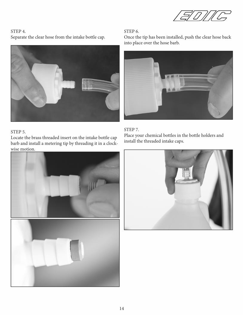
STEP 4.Separate the clear hose from the intake bottle cap.
STEP 5.Locate the brass threaded insert on the intake bottle cap barb and install a metering tip by threading it in a clock-wise motion.
STEP 6. Once the tip has been installed, push the clear hose back into place over the hose barb.
STEP 7.Place your chemical bottles in the bottle holders and install the threaded intake caps.
14
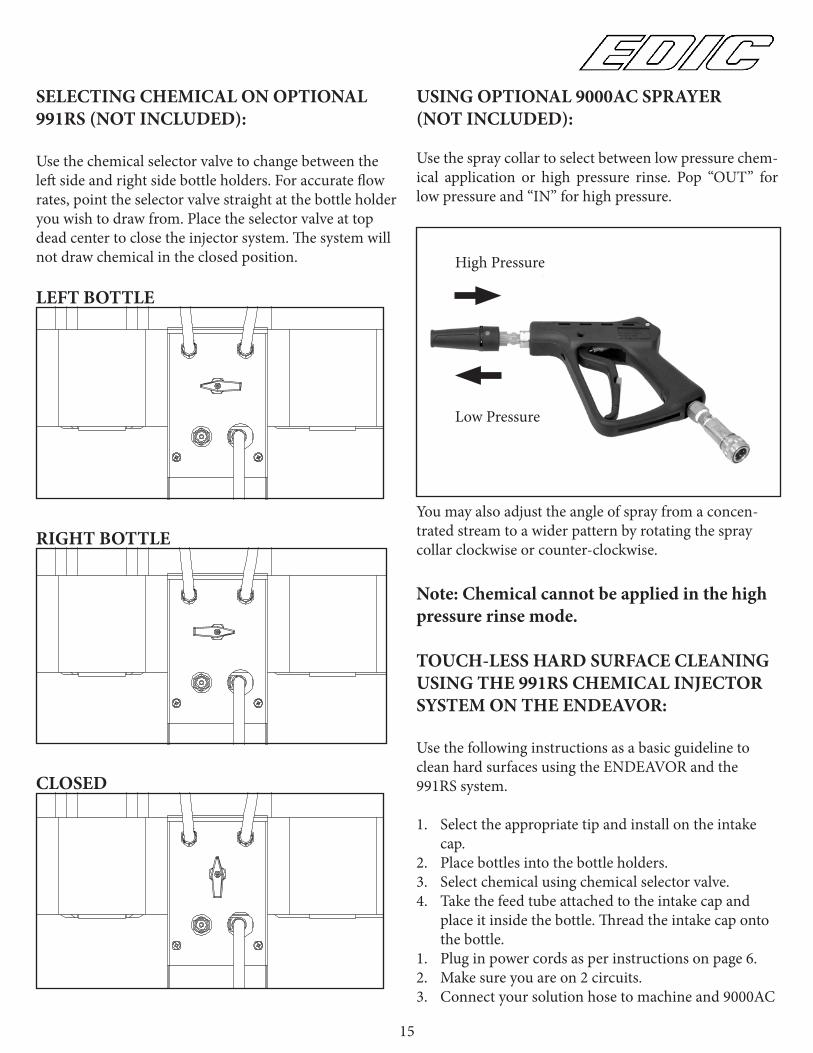
SELECTING CHEMICAL ON OPTIONAL 991RS (NOT INCLUDED):
Use the chemical selector valve to change between the left side and right side bottle holders. For accurate flow rates, point the selector valve straight at the bottle holder you wish to draw from. Place the selector valve at top dead center to close the injector system. The system will not draw chemical in the closed position.
LEFT BOTTLE
RIGHT BOTTLE
CLOSED
USING OPTIONAL 9000AC SPRAYER (NOT INCLUDED):
Use the spray collar to select between low pressure chem-ical application or high pressure rinse. Pop “OUT” for low pressure and “IN” for high pressure.
You may also adjust the angle of spray from a concen-trated stream to a wider pattern by rotating the spray collar clockwise or counter-clockwise.
Note: Chemical cannot be applied in the high pressure rinse mode.
TOUCH-LESS HARD SURFACE CLEANING USING THE 991RS CHEMICAL INJECTOR SYSTEM ON THE ENDEAVOR:
Use the following instructions as a basic guideline to clean hard surfaces using the ENDEAVOR and the 991RS system.
1. Select the appropriate tip and install on the intake cap.
2. Place bottles into the bottle holders.3. Select chemical using chemical selector valve.4. Take the feed tube attached to the intake cap and
place it inside the bottle. Thread the intake cap onto the bottle.
1. Plug in power cords as per instructions on page 6.2. Make sure you are on 2 circuits. 3. Connect your solution hose to machine and 9000AC
High Pressure
Low Pressure
15

spray gun.4. Fill the machine with water. See page 10 for auto fill
instructions.5. Prime the pump as per instructions on page 9. 6. Adjust the pressure to 500psi. See instructions on
page 9.7. Chemical will draw only in the “LOW” pressure
setting of your pressure gun. To activate the “LOW” pressure setting, pop the collar of the gun out.
8. In “LOW” pressure, apply chemical to the walls and fixtures starting from the lowest point to the highest.
9. Spray the floor as you make your way out of the room.
10. Allow the chemical time to dwell according to the chemical manufacturers recommendations.
11. You may use a brush to agitate particularly soiled areas.
12. When you are ready to rinse away the chemical, pull the collar of your 9000AC “IN”, to activate high pressure rinse mode. If you require a higher volume of flow for rinse mode, you may bypass the 991RS chemical injector system by connecting your 25ft hose directly to the male quick connect on the EN-DEAVOR’s control panel.
13. Rinse surfaces starting from the top and working your way down.
14. Use a 334ACH squeegee wand to extract the excess fluid from the floor.
16
17
4017
2016
10
36
13
12
19
15
4241
6
14 433453
21
2
30
38
25 7 289
14
3937
1127
2233
24
29
31 26
35
1832
23
11
11
8
39
814
3
9000I-HSHEN
DEA
VO
R SOLUTIO
N TA
NK
EXPLOD
ED V
IEW5/5/2017

18
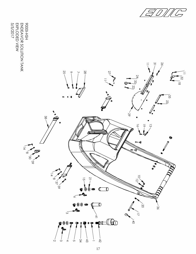
9000I-HSHENDEAVOR SOLUTION TANK EXPLODED VIEW5/5/2017
ITEM NO. PART NUMBER DESCRIPTION QTY.
1 A00118 BUSHING, 1/4 FP X 3/8 SAE 12 A11949 3/8 MF 90 DEGREE ELBOW 33 A13271 3/8 FP X 1/2 BARB, ELBOW 24 A13445 3/8 MIP HEX NIPPLE 35 A13606 3/8 X 1/4 FIP X MIP, ADP 16 A13849 ELBOW, 90 DEGREE, 3/8H x 3/8F 17 C00233 WASHER, FLAT, USS, 1/4 28 C00233-1 WASHER, FLAT, 1/4 SS 49 C00254 LOCKWASHER, 1/4 SPLIT 2
10 C00279 LOCKNUT, 3/8 NYLON, ZINC 211 C00311 SCREW, 8-32 x .375 712 C10503 WASHER, FLAT 1 x .048 213 C12039 FENDER WASHER, 1/4" ID, 1" OD 314 C13351 SCREW, 10-32 x 3/4, TRUSS, SS 415 C13421 WASHER, .687 ID, 1.5 OD 316 C13535 SCREW, 10-32 X 1, HEX 317 C13559 HEX BOLT, 5/16 X 5 1/2, SS 218 C13666 NUT, KEP, 8-32 SS 519 C13740 LOCKWASHER, #10, SPLIT 320 C13859 WASHER, NEOPRENE BONDED 421 C13871 WASHER, 11/16, SS 322 C13939 NUT, KEP, #4-40, SS 123 C13940 NUT, KEP, 10-32, SS 424 C13948 SCREW, #4-40 X 3/8 PH 125 C90007 SCREW, 10-32 x 5/8, TRUSS HEAD 226 C90007-1 10-32 X 1, TRUSS, SS 427 D13315 HANDLE, LID 128 D13347 LATCH NOSE, TOP 129 D13355 LID, SOLUTION TANK 130 D13362 D-PLATE, STRAP 131 D13479 HINGE 132 D13912 CATCH, LID MAGNET 133 D13926 MAGNET, CUP 134 E13653 O-RING, SILICONE 235 E13924 GASKET, LID HINGE 236 F13295 SOLUTION TANK, BLUE GRANITE 137 F13548 STRAP, VELCRO, SHORT 238 F13549 STRAP, VELCRO, LONG 139 K00727 SPACER, .5 OD X .257 ID X .3 H 440 K10510 PLUG, 1" ROUND, SNAP-IN 241 K13398 FILTER, SUCTION, 80 MESH 242 K13510 FILL VALVE, ANTI-SIPHON 143 K13966 SUPPLY NUT 1

19
59
31
11
79
6061
494751
81
3371
72
68
50
3674
22
217077
67
24
6913
14
4
32
1226
23
19
41
29
1827
38 3028
4417 40
395557 3159
37
58
75
64
34 52
7380
65
4366
63
4546
2076
78
25
35
62
7 16
4854
156
538
102
42
56
43
74
34
2
9
2
17
17
24
29
8
63
21
60
9000I-HSHEN
DEA
VO
R RECO
VERY TA
NK
EXPLOD
ED V
IEW5/5/2017
20
9000I-HSHENDEAVOR RECOVERY TANK EXPLODED VIEW5/5/2017
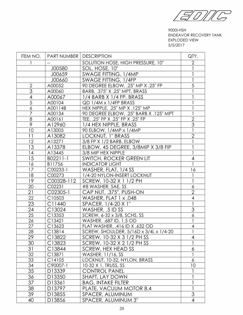
ITEM NO. PART NUMBER DESCRIPTION QTY.1 -- SOLUTION HOSE, HIGH PRESSURE, 10" 2
J00580 SOL. HOSE, 10" 1J00659 SWAGE FITTING, 1/4MP 1J00660 SWAGE FITTING, 1/4FP 1
2 A00052 90 DEGREE ELBOW, .25" MP X .25" FP 53 A00060 BARB, .375" X .25" MPT, BRASS 14 A00067 1/4 BARB X 1/4 FP, BRASS 15 A00104 QD 1/4M x 1/4FP BRASS 16 A00114B HEX NIPPLE, .25" MP X .125" MP 17 A00134 90 DEGREE ELBOW, .25" BARB X .125" MPT 18 A00161 TEE, .25" FP X .25" FP X .25" FP 29 A12960 1/4 HEX NIPPLE, BRASS 310 A13005 90 ELBOW, 1/4MP x 1/4MP 111 A13082 LOCKNUT, 1" BRASS 212 A13271 3/8 FP X 1/2 BARB, ELBOW 113 A13378 ELBOW, 45 DEGREE, 3/8MIP X 3/8 FIP 114 A13445 3/8 MIP HEX NIPPLE 115 B02211-1 SWITCH, ROCKER GREEN LIT 416 B11756 INDICATOR LIGHT 117 C00233-1 WASHER, FLAT, 1/4 SS 1618 C00273 1/4-20 NYLON-INSERT LOCKNUT 119 C00328-112 SCREW, 10-32 X 1 1/2 PH 120 C02231 #8 WASHER, SAE, SS 621 C02305-1 CAP NUT, .375", PUSH-ON 222 C10503 WASHER, FLAT 1 x .048 423 C11440 SPACER, 1/4-20 X 1" 124 C13024 WASHER, .5 ID SS 325 C13353 SCREW, 6-32 x 3/8, SCHS, SS 626 C13421 WASHER, .687 ID, 1.5 OD 127 C13623 FLAT WASHER, .416 ID X .632 OD 428 C13814 SCREW, SHOULDER, 5/16D x 3/4L x 1/4-20 129 C13822 SCREW, 10-32 X 3 1/2 PH SS 430 C13823 SCREW, 10-32 X 2 1/2 PH SS 131 C13844 SCREW, HEX HEAD SS 632 C13871 WASHER, 11/16, SS 133 C14105 LOCKNUT, 10-32, NYLON, BRASS 634 C90007-1 10-32 X 1, TRUSS, SS 1035 D13339 CONTROL PANEL 136 D13350 SHAFT, LAY DOWN 137 D13361 BAG, INTAKE FILTER 138 D13797 PLATE, VACUUM MOTOR 8.4 139 D13855 SPACER, ALUMINUM 340 D13856 SPACER, ALUMINUM 3" 4

21
9000I-HSHENDEAVOR RECOVERY TANK EXPLODED VIEW5/5/2017
ITEM NO. PART NUMBER DESCRIPTION QTY.41 D13857 SPACER, ALUMINUM 2" 142 D14140 U-CLAMP 143 E11128 GASKET, DRAIN VALVE 244 E13338 GASKET 145 E13686-A GASKET, AIR INTAKE 146 E13686-B GASKET, AIR INTAKE 147 E13830 GASKET, RECOVERY LID 148 F12118 HOLE COVER, SWITCH 149 F13242 DECK PLATE 150 F13294 RECOVERY TANK, GREY GRANITE 151 G02531-1 WHEEL, 4 INCH 252 G13247 PUMP, WASTE WATER 153 G13335 GAUGE, 2000PSI 154 G13380 VALVE, PRESSURE RELIEF 155 G13796 VACUUM MOTOR, 2 STAGE, 8.4 156 G14041 REGULATOR, 1200 PSI 157 J00618 HOSE, 2"ID GREY, 20" L 158 J00621 VAC HOSE, 2"ID BLACK, 23" L 159 J00639 CLAMP, HOSE 2.0 460 J00651 HOSE CLAMP, .25" TO .625" 461 J11154 SOL. HOSE, 100 PSI WIRE, .375" ID X 42" L 162 J11154-1 SOL. HOSE .25" ID X 30" L 163 J11508 SCREW CLAMP, #6 264 J11933 1/2" POLYWIRE PVC HOSE, 22" 165 J11933 1/2" POLYWIRE PVC HOSE, 34" 166 K00665-1 HOSE ADAPTER, 1.5 INCH 167 K00711 DRAIN VALVE, BLACK 168 K13364 FLOAT, SHUT-OFF 169 K13397 FILTER, SUCTION, 60 MESH 170 K13400 ADAPTER, 2" HUB x MIPT 171 K13405 PIPE, 2" SCH40 ABS, 1.625"L 172 K13405 PIPE, 2" SCH40, ABS, 12.375"L 173 K13406 PIPE, 1.5" ABS. 1.5"L 174 K13476 ELBOW, 2 IN. 22-1/2 DEG 375 K13477 REDUCER, 2" x 1 1/2"ABS 176 K13741 ADAPTER, FEMALE 1 1/2" 177 K13805 INSERT, BARB, 2H, 2MPT 178 K13843 ADAPTER, 1.5" PVC, SCH40 179 K13864 ELBOW, 45 DEGREE 180 K13872 COUPLING, 1-1/2, NO THREAD 181 K13873 RETURN BEND, ABS 2" 1

22
67
52
84
13
4282
1541
188324
48
3162
14
68
29
25
43
81
38
877
16
1033
665
57
9
8073
74
34
7678
617560
59
46
1155 663644
51
27
79
5664
34
21
5845 21
1940
8520
26 86
72 23 3763
28 53 5769
49
71 70
47 54 12
1735
50
39 32
22
3076
2119
19
30
1923
19 23
66 36 23
9000I-HSHEN
DEA
VO
R BASE
EXPLOD
ED V
IEW5/5/2017
23
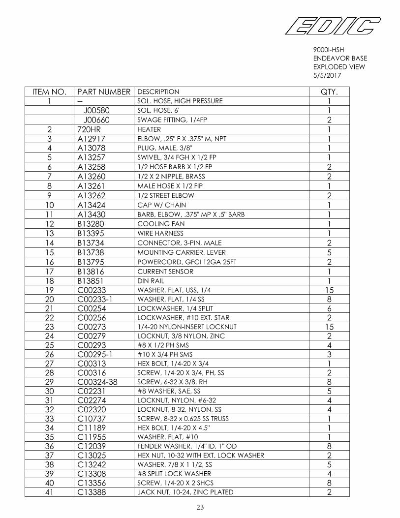
9000I-HSHENDEAVOR BASE EXPLODED VIEW5/5/2017
ITEM NO. PART NUMBER DESCRIPTION QTY.1 -- SOL. HOSE, HIGH PRESSURE 1
J00580 SOL. HOSE, 6' 1J00660 SWAGE FITTING, 1/4FP 2
2 720HR HEATER 13 A12917 ELBOW, .25" F X .375" M, NPT 14 A13078 PLUG, MALE, 3/8" 15 A13257 SWIVEL, 3/4 FGH X 1/2 FP 16 A13258 1/2 HOSE BARB X 1/2 FP 27 A13260 1/2 X 2 NIPPLE, BRASS 28 A13261 MALE HOSE X 1/2 FIP 19 A13262 1/2 STREET ELBOW 2
10 A13424 CAP W/ CHAIN 111 A13430 BARB, ELBOW, .375" MP X .5" BARB 112 B13280 COOLING FAN 113 B13395 WIRE HARNESS 114 B13734 CONNECTOR, 3-PIN, MALE 215 B13738 MOUNTING CARRIER, LEVER 516 B13795 POWERCORD, GFCI 12GA 25FT 217 B13816 CURRENT SENSOR 118 B13851 DIN RAIL 119 C00233 WASHER, FLAT, USS, 1/4 1520 C00233-1 WASHER, FLAT, 1/4 SS 821 C00254 LOCKWASHER, 1/4 SPLIT 622 C00256 LOCKWASHER, #10 EXT. STAR 223 C00273 1/4-20 NYLON-INSERT LOCKNUT 1524 C00279 LOCKNUT, 3/8 NYLON, ZINC 225 C00293 #8 X 1/2 PH SMS 426 C00295-1 #10 X 3/4 PH SMS 327 C00313 HEX BOLT, 1/4-20 X 3/4 128 C00316 SCREW, 1/4-20 X 3/4, PH, SS 229 C00324-38 SCREW, 6-32 X 3/8, RH 830 C02231 #8 WASHER, SAE, SS 531 C02274 LOCKNUT, NYLON, #6-32 432 C02320 LOCKNUT, 8-32, NYLON, SS 433 C10737 SCREW, 8-32 x 0.625 SS TRUSS 134 C11189 HEX BOLT, 1/4-20 X 4.5" 135 C11955 WASHER, FLAT, #10 136 C12039 FENDER WASHER, 1/4" ID, 1" OD 837 C13025 HEX NUT, 10-32 WITH EXT. LOCK WASHER 238 C13242 WASHER, 7/8 X 1 1/2, SS 539 C13308 #8 SPLIT LOCK WASHER 440 C13356 SCREW, 1/4-20 X 2 SHCS 841 C13388 JACK NUT, 10-24, ZINC PLATED 2

24
9000I-HSHENDEAVOR BASE EXPLODED VIEW5/5/2017
ITEM NO. PART NUMBER DESCRIPTION QTY.42 C13389 SCREW, 10-24 X 1 1/2, TRUSS 243 C13391 SCHS 3/8-16 x 4 1/2 SS 244 C13431 1/4-20 X 2 1/2 SHCS, ZINC PLATED 445 C13432 1/4-20 X 1 1/2 SHCS, ZINC PLATED 246 C13433 LOCKNUT, 5/16-18, NYLON 147 C13434 8-32 X 2 1/4 SHCS, SS 448 C13623 FLAT WASHER, .416 ID X .632 OD 449 C13834 SCREW, #6 X 2 SMS, SS 150 C13847 SCREW, #12 X 1 1/2 FH SMS SS 151 C13861 E-RING, 5/8 252 C13871 WASHER, 11/16, SS 153 C14093 SCREW, 10-32 X 1, FHS SS 254 D13281 FAN GUARD, 92MM 255 D13340 BRACKET, PUMP 156 D13343 BRACKET, HEATER 157 D13348 LATCH, NOSE, BOTTOM 158 D13356 SHAFT, MAIN AXLE 159 D13435 BALL MOUNT, GAS SPRING 160 D13436 BALL SOCKET, 10MM 161 D13437 EYELET, GAS SPRING 162 D13729 CAP, POWER, ENTRY 263 D14057 PLATE, WASHER 164 E00449 GROMMET 165 E13246 WASHER, WATER HOSE 266 E13440 GROMMET, .278ID 1267 F13296 BASE, BLUE GRANITE 168 F13820 LOUVER, 3", BLACK 269 F13832 SPACER, .375 OD, .192 ID 170 F13833 BOX POTTING 171 G11609 SENSOR, CIRCUIT 172 G13218 CASTER, 4" TWIN WHEEL 273 G13248 WHEEL, 12 INCH 274 G13333 PUMP, 1100 PSI 175 G13801 GAS SPRING, 120 LB RATED 176 J11508 SCREW CLAMP, #6 477 J11933 1/2" POLYWIRE PVC, HOSE, 43" 178 J11933 1/2" POLYWIRE PVC HOSE, 55" 179 J13385A PULSE HOSE ASSEMBLY, 24 INCH 180 J14110A PULSE HOSE ASSEMBLY, 50 INCH 181 K00672 PIPE, 1 1/2 SCH40, PVC, 9" 182 K00727 SPACER, .5 OD X .257 ID X .3 H 283 K010142 PLUG, 2" BLACK 184 K13403 BUSHING, J-FLANGE, .625 ID 285 K13602 HANDLE, PULL BACK 186 K13828 FLANGE, 1 1/2 PIPE FITTING 1