9 design of plate girders
DESCRIPTION
Structural referenceTRANSCRIPT
Design of Plate Girders
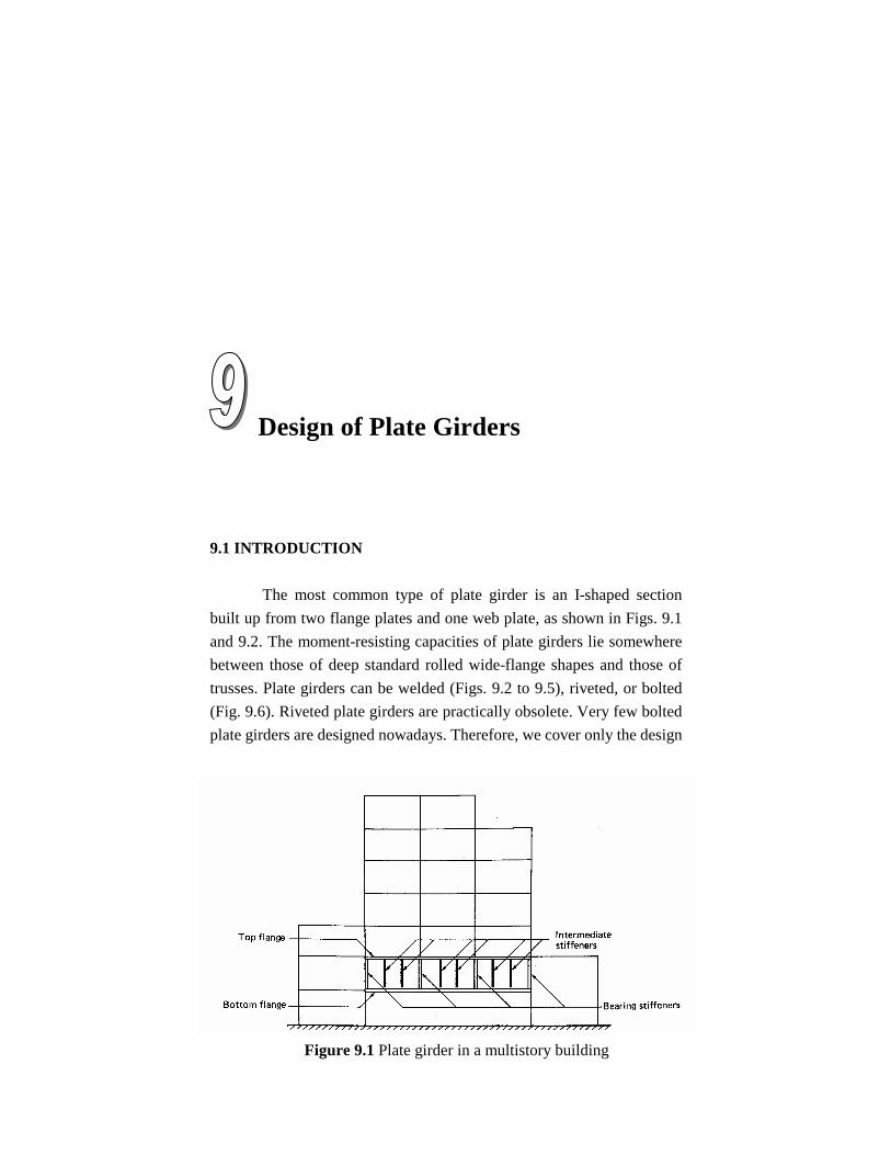
9.1 INTRODUCTION The most common type of plate girder is an I-shaped section built up from two flange plates and one web plate, as shown in Figs. 9.1 and 9.2. The moment-resisting capacities of plate girders lie somewhere between those of deep standard rolled wide-flange shapes and those of trusses. Plate girders can be welded (Figs. 9.2 to 9.5), riveted, or bolted (Fig. 9.6). Riveted plate girders are practically obsolete. Very few bolted plate girders are designed nowadays. Therefore, we cover only the design
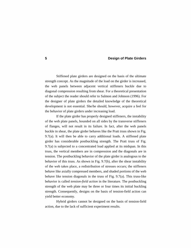
Figure 9.1 Plate girder in a multistory building
Design of Plate Girders 2
of welded plate girders in this book. Plate girders are used in both buildings and bridges. In buildings, when large column-free spaces are designed to be used as an assembly hall, for example, the plate girder is often the economical solution. In such cases, the designer must choose between a plate girder and a truss. Plate girders, in general, have the following advantages over trusses:
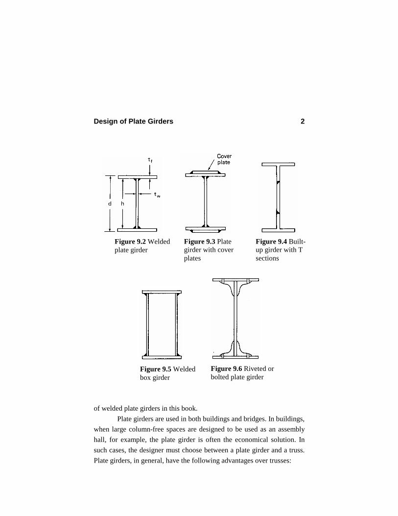
Figure 9.2 Welded plate girder
Figure 9.5 Welded box girder
Figure 9.6 Riveted or bolted plate girder
Figure 9.4 Built-up girder with T sections
Figure 9.3 Plate girder with cover plates
Design of Plate Girders 3
1. Connections are less critical for plate girders than for trusses,
particularly statically determinate trusses. In a statically determinate truss, one poor connection may cause the collapse of the truss.
2. Fabrication cost of plate girders is less than that of trusses. 3. Plate girders can be erected more rapidly and more cheaply than
trusses. 4. Depth of a plate girder is less than the height of a comparable truss.
Consequently, plate girders need less vertical clearance than trusses. This makes them very attractive for multilevel highway bridges.
5. Plate girders generally vibrate less than trusses under moving loads.
6. Painting of plate girders is easier than painting of trusses. This means less maintenance cost for plate girders.
In contrast, plate girders in general are heavier than trusses, especially for very long spans. Plate girders basically carry the loads by bending. The bending moment is mostly carried by flange plates. In order to reduce the girder weight and possibly achieve maximum economy, hybrid plate girders are sometimes used. In a hybrid girder, flange plates are made of higher-strength steel than that of the web. Or, in a tee-built-up plate girder, as shown in Fig. 9.4, the two T sections are made of higher-strength steel than the connecting web plate. Design of hybrid plate girders is also covered in this chapter. Allowable bending stress for hybrid girders is limited to 0.60Fy (ASD F1).
Design of Plate Girders 4
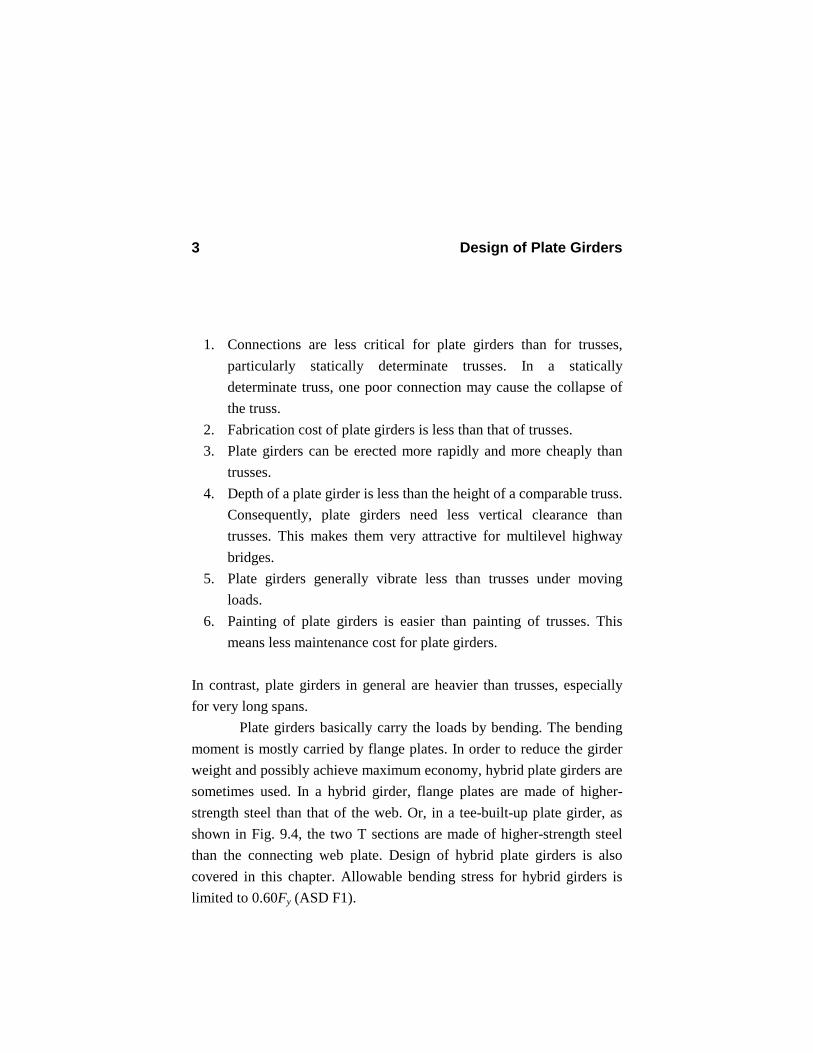
9.2 POSTBUCKLING BEHAVIOR OF THE WEB PLATE In addition to flange plates and a web plate, a plate girder often consists of intermediate and bearing stiffeners. As mentioned in the previous section, the two flange plates basically carry the bending moment. A web plate is needed to unify the two flange plates and to carry the shear. Thin web plates are susceptible to unstable behavior. Thick web plates make the girder unnecessarily heavy. A relatively thin web plate strengthened by stiffeners often yields the lightest plate girder.
Figure 9.7 Analogy between a truss and a stiffened plate girder
Design of Plate Girders 5
Stiffened plate girders are designed on the basis of the ultimate strength concept. As the magnitude of the load on the girder is increased, the web panels between adjacent vertical stiffeners buckle due to diagonal compression resulting from shear. For a theoretical presentation of the subject the reader should refer to Salmon and Johnson (1996). For the designer of plate girders the detailed knowledge of the theoretical development is not essential. She/he should, however, acquire a feel for the behavior of plate girders under increasing load. If the plate girder has properly designed stiffeners, the instability of the web plate panels, bounded on all sides by the transverse stiffeners of flanges, will not result in its failure. In fact, after the web panels buckle in shear, the plate girder behaves like the Pratt truss shown in Fig. 9.7(a). It will then be able to carry additional loads. A stiffened plate girder has considerable postbuckling strength. The Pratt truss of Fig. 9.7(a) is subjected to a concentrated load applied at its midspan. In this truss, the vertical members are in compression and the diagonals are in tension. The postbuckling behavior of the plate girder is analogous to the behavior of this truss. As shown in Fig. 9.7(b), after the shear instability of the web takes place, a redistribution of stresses occurs; the stiffeners behave like axially compressed members, and shaded portions of the web behave like tension diagonals in the truss of Fig. 9.7(a). This truss-like behavior is called tension-field action in the literature. The postbuckling strength of the web plate may be three or four times its initial buckling strength. Consequently, designs on the basis of tension-field action can yield better economy. Hybrid girders cannot be designed on the basis of tension-field action, due to the lack of sufficient experiment results.
Design of Plate Girders 6
9.3 PROPORTIONING OF THE WEB PLATE At the outset, we must initially choose a value for the depth h of the web plate. As a general guideline, experience shows that the ratio of the depth of the web plate h to span length L varies from 1/25 to 1/6.
61
251 ≤≤
Lh (9.1)
This ratio, however, is often within the range 1/15 to 1/10.
101
151 ≤≤
Lh (9.2)
Deeper girders are generally used when the loads are heavy (for example, when they need to carry large column loads in high-rise buildings). Very shallow girders with 1/25 < h/L < 1/15 are used as continuous plate girders. In design of plate girders, we should design the plate girder with several different values of the web depth-to-span ratios and find the total weight of the plate girder for each case. By drawing the total weight versus h/L ratio, we can obtain an economical (practical approximate optimum or minimum weight) solution for our design. Of course, repetitive manual design of plate girders is quite cumbersome and time-consuming. However, with the aid of the interactive program (to be discussed in Sec. 9.12), the final design can be achieved quickly. Totally automated optimum design of stiffened plate girders is rather complicated due to the highly nonlinear nature of the problem. Abuyounes and Adeli (1986, 1987) present algorithms for minimum weight design of simply supported steel homogeneous and hybrid plate girders. Adeli and Chompooming (1989) present minimum weight
Design of Plate Girders 7
design of continuous prismatic and nonprismatic plate girders. Adeli and Mak (1990) present minimum weight design of plate girder bridges subjected to moving loads. In this book, however, our approach is interactive design, which is presented in Sec. 9.12. After the h/L ratio has been selected, the depth of the web plate will be known. The next step is to choose the web thickness. The web thickness is chosen based on the following two criteria:
1. The web plate should have sufficient buckling strength to prevent vertical buckling of the compression flange into the web.
2. The web plate should carry all the shearing force.
In calculating the shear strength of the web, it is assumed that the shear stress distribution is uniform throughout the web depth.
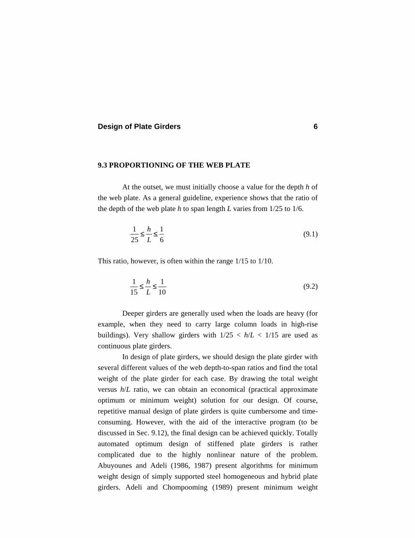
Figure 9.8 Squeezing of the web due to bending of the girder during tension-field action
Design of Plate Girders 8
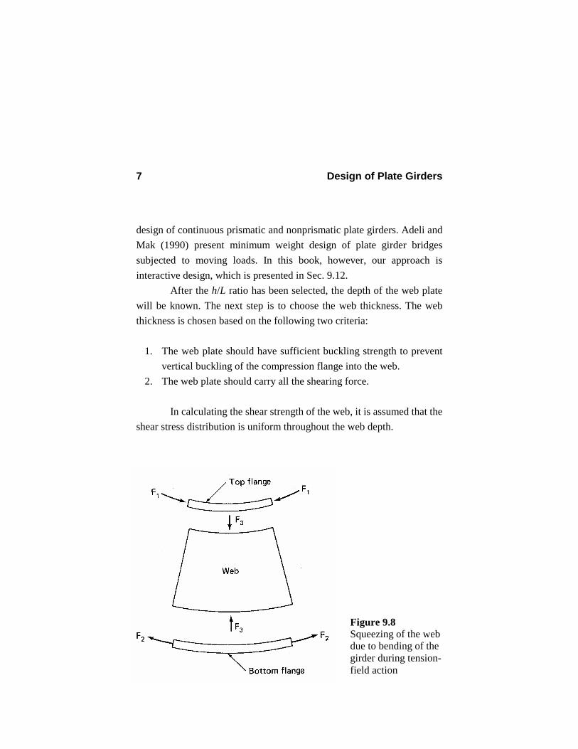
During the postbuckling behavior of the web plate, the bending curvature of the plate girder produces compressive forces in the web plate, as shown in Fig. 9.8. This figure shows a portion of the plate girder located between two neighboring sections. Due to the deflected shape of the girder, the compressive force F1, acting on the top compression flange and the tension force F2 acting in the bottom tension flange create compressive forces F3 on the web plate. This plate should have sufficient buckling strength to resist the compressive forces F3. To satisfy this requirement, according to ASD G1, the web depth-thickness ratio should not be greater than α1, which is a decreasing function of the yield stress of the compression flange Fyf.
Fyf
Fyf
Fyf
Figure 9.9
Fyf Fyf
Fyf
Design of Plate Girders 9
2/11 )]5.16([
000,14+
=≤yfyfw FFt
h α (9.3)
The variation of α1 with Fyf is shown in Fig. 9.9. This equation is derived from a stability analysis of the web plate, taking into account the effect of residual stresses but without including the transverse stiffeners. For closely spaced stiffeners – that is, when spacing of the transverse stiffeners a is not greater than 1.5 times the distance between flanges – the limiting ratio α1 is increased to α2.
h.aFt
h
yfw51en wh000,2
2 ≤=≤ α (9.4)
The variable α2 is also shown in Fig. 9.9. Note that the difference between α1 and α2 increases with an increase in the yield stress. For high-strength steel, α2 is much larger than α1. To satisfy the second criterion, we should have
v
w hFVt ≥ (9.5)
where V is the shear force and Fv is the allowable shear stress given in ASD F4.
40.089.2 y
vyv F
CFF ≤= for 380
yw Fth > (9.6)
where
Design of Plate Girders 10
=vC 2)/(
000,45
wy
v
thFk
when Cv ≤ 0.8
yw
v
Fth
k
/
190 when Cv > 0.8
(9.7)
=vk 2)/(
34.500.4ha
+ when a/h < 1.0 (kv > 9.34)
2)/(00.434.5ha
+ when a/h ≥ 1.0 (9.8)
Note that Cv is the ratio of shear stress at buckling to the shear yield stress (Salmon and Johnson, 1996). For hybrid girders, Fy in Eqs. (9.6) and (9.7) is the yield stress of the web steel. We can increase the allowable shear stress by relying on the postbuckling behavior and tension-field action of the web plate, provided that the following conditions are met (ASD F5 and G3):
1. The plate girder is not a hybrid one 2. Intermediate stiffeners are provided 3. Cv ≤ 1.0 (9.9) 4. a/h ≤ [260/(h/tw)]2 (9.10) 5. a/h ≤ 3.0 (9.11)
The last two conditions are somewhat arbitrarily chosen limits on the panel aspect ratio a/h to facilitate handling during fabrication and erection. When the effect of tension-field action is taken into account, the allowable shear stress is given by (ASD G3)
Design of Plate Girders 11
y
vv
yv F
haC
CF
F 40.0)/1(15.1
189.2 2/122 ≤
+−
+= (9.12)
Note that the second term within the brackets is the tension-field contribution. One may select the web thickness based on the first criterion [Eqs. (9.3) and (9.4)] and then check for the second criteron [Eq. (9.5)]. In this case the maximum computed shear stress (fv)max must be less than the allowable shear stress Fv.
vw
v Fht
Vf ≤= max
max)( (9.13)
After preliminary proportioning of the web plate, we may check if intermediate stiffeners are needed. According to ASD F5, intermediate stiffeners are not required if
260<wth (9.14)
and the maximum shear stress in the web is less than the allowable shear stress given by Eq. (9.6). Equation (9.6) can be specialized for the case of no stiffeners. For very large a/h, Eq. (9.8) yields k = 5.34. Substituting this value of k into Eq. (9.7) and the resulting values into Eq. (9.6), we finally find the following equation for the allowable shear stress when intermediate stiffeners are not needed:
Design of Plate Girders 12
=vF
2)/(150,83
wth when
yw Fth 548
>
w
y
th
F
/
152 when
ywy Fth
F548380 ≤<
yF40.0 when yw Ft
h 380≤
(9.15)
It should be noted that plate girders with intermediate stiffeners are generally lighter than plate girders without intermediate stiffeners. To prevent the undesirable consequences of corrosion, an absolute minimum web thickness is usually specified in practice. A minimum thickness of 3/8 in. is recommended for bridge plate girders. For plate girders used in buildings which are not exposed to the harsh corrosive environment, a smaller absolute minimum web thickness of ¼ in. is suggested. 9.4 PROPORTIONING OF THE FLANGES 9.4.1 Preliminary Calculation of Flange Area The aim is to select a flange plate of area sufficient to carry the maximum bending moment Mmax.
bFM
S max Required = (9.16)
In this equation, S is the elastic section modulus with respect to the major axis and Fb is the allowable bending stress given in the ASD F1 and

Design of Plate Girders 13
discussed in Chapter 5. We can find an approximate relation for the section modulus. The moment of inertia of the section with respect to the major axis is 3
12223
121 )2/2/(2 fffffw tbthtbhtI +++=
23121 )2/(2 hAhtI fw +≈
(9.17)
where bf is the width of the flange plate, tf is the thickness of the flange plate, and Af = bf tf = area of the flange. The elastic section modulus is then approximately equal to
hAht
hI
dIS f
w +=≈=62/2/
2
(9.18)
By equating Eqs. (9.16) and (9.18) and solving for Af, we find an equation for the preliminary estimate of the area of the flange.
66maxmax w
b
w
bfff
AhF
MhthF
MtbA −=−≈= (9.19)
In this equation, Aw = tw h is the web area. 9.4.2 Preliminary Selection of the Flange Plate In order to avoid local flange buckling, the width-thickness ratio of the flange plate is limited by ASD B5 (Table 5.1 in the text).
Design of Plate Girders 14
cyf
f
kFtb
/190≤
(9.20)
=ck 701
70)/(
05.4
46.0
≤
>
w
ww
th
th
th (9.21)
To find the minimum flange thickness required, we set
fcy
f tkF
b/
190= (9.22)
Substituting Eq. (9.22) into Eq. (9.19) and solving for tf, we obtain 2/12/1
max
190
/
6190
/
=
−= f
cyw
b
cyf A
kFhthF
MkFt (9.23)
This equation roughly gives the minimum flange thickness required to prevent the local buckling of the flange plate. We may round this thickness to a commercially available size, for example, as a fraction of 1/16 in., and use it as the trial design thickness of the flange plate. However, in many cases, this design would result in very thin and wide flange plates. Therefore, the designer may wish to choose a flange thickness larger than that obtained by Eq. (9.23). After selecting the thickness of the flange plate, we find the required flange width bf from Eq. (9.19).
Design of Plate Girders 15
At this point, we can calculate the exact value of the moment of inertia of the section from Eq. (9.17) and check if the available section modulus is at least equal to Mmax /Fb. 9.4.3 Reduction of the Allowable Bending Stress In regions of large bending moments, a thin web plate may deflect laterally on its compression side. When this happens the bending stress distribution over the depth of the girder will no longer be linear. The result will be a reduction in the bending stress capacity of the web and transfer of additional stresses to the compression flange. Instead of performing a rather complicated nonlinear analysis to find the increased maximum stress in the flange, ASD G2 requires that the allowable bending stress in the compression flange to be reduced to F’b when the web depth-thickness ratio exceeds yF/970 .
ebwf
wbb R
Fth
AA
FF
−−≤ 7600005.00.1' when
yw Fth 970> (9.24)
In this equation, Aw is the web area. When h/tw < ,/970 yF no
reduction of the allowable bending stress is necessary. Note that when the compression flange does not have sufficient lateral support, the allowable bending stress Fb must be reduced according to ASD F1, as discussed in Sec. 5.5, to take into account the possibility of lateral torsional buckling. Re is the hybrid beam coefficient given by
Design of Plate Girders 16
( )
0.1
62
312 3
≤
+
−+=
f
w
f
w
e
AA
AA
Rαα
(9.25)
where Fyw is the web yield stress, α= 0.60Fyw /Fb ≤ 1.0, and Fb is the allowable bending stress after the lateral-torsional buckling has been considered, when it is assumed that the entire member is made of the grade of the steel used in the flanges. This equation is intended to account for the effect on the strength of a hybrid girder with a web of low yield strength. Equation (9.25) is applicable only when the area and grade of steel in both flanges are the same. Otherwise, a more complicated analysis is required. For nonhybrid girders, Re = 1.0. If reduction of the allowable bending stress is necessary, we should check if the computed bending stress is less than the reduced allowable bending stress.
'maxbb F
SM
f <= (9.26)
9.5 INTERMEDIATE STIFFENERS Intermediate stiffeners are provided to stiffen the web plate against buckling and to resist compressive forces transmitted from the web during tension-field action. They are designed based on the following requirements: 1. When the design of plate girder is based on tension-field action, the
gross area of each intermediate stiffener or the total area of a pair of
Design of Plate Girders 17
stiffeners, when they are used in pairs, should be at least equal to (ASD G4)
+−−=
v
v
ys
ywvwst F
ff
F
haha
haCDhtA 2/122
22
)/1(/)1(
21 (9.27)
where fv is the greatest computed shear stress in the panel under consideration, Fys is the yield stress of the stiffener, and
2.4 for single plate stiffeners 1.0 for stiffeners used in pairs D = 1.8 for single angle stiffeners
During tension-field action the intermediate stiffeners behave as short struts. The required area by Eq. (9.27) ensures sufficient compression capacity of the stiffeners. Due to eccentric transfer of load with respect to the web, single-sided stiffeners are subject to considerable bending moment in addition to axial load and consequently are substantially less efficient than double-sided stiffeners. This consideration is reflected in Eq. (9.27) by the variable D.
2. The moment of inertia of a single intermediate stiffener or a pair of intermediate stiffeners (Ist) with respect to an axis in the plane of the web and perpendicular to the plane of the stiffener(s) (axis X-X in Fig. 9.10) should be at least equal to (ASD G4)
4)50/(hI st = (9.28)
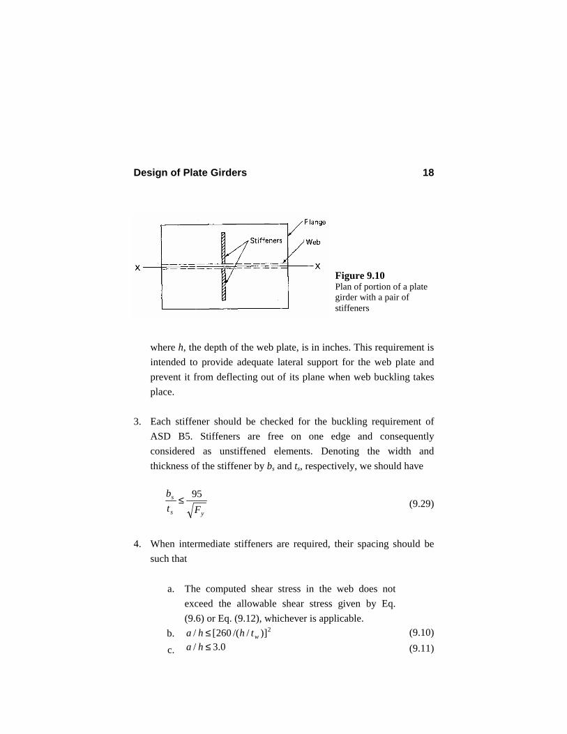
Design of Plate Girders 18
where h, the depth of the web plate, is in inches. This requirement is intended to provide adequate lateral support for the web plate and prevent it from deflecting out of its plane when web buckling takes place.
3. Each stiffener should be checked for the buckling requirement of
ASD B5. Stiffeners are free on one edge and consequently considered as unstiffened elements. Denoting the width and thickness of the stiffener by bs and ts, respectively, we should have
ys
s
Ftb 95≤ (9.29)
4. When intermediate stiffeners are required, their spacing should be
such that
a. The computed shear stress in the web does not exceed the allowable shear stress given by Eq. (9.6) or Eq. (9.12), whichever is applicable.
b. 2)]//(260[/ wthha ≤ (9.10)
c. 0.3/ ≤ha (9.11)
Figure 9.10 Plan of portion of a plate girder with a pair of stiffeners
Design of Plate Girders 19
d. yyv
vbb FF
Ff
Ff 60.0375.0825.0 ≤
−=≤ (9.30)
The last requirement should be met only when the design of the web plate is based on tension-field action. In this case, due to large shear stresses in the web, the maximum tensile stress which acts at an angle to the girder axis could be considerably larger than the maximum tensile stress parallel to the girder axis. In lieu of a lengthy analysis for finding the maximum tensile stress based on the combined shear and tension stresses, ASD G5 requires that Eq. (9.30) be satisfied, in which fb is the maximum bending tensile stress due to moment in the plane of the girder web. According to ASD Commentary G5, the interaction equation (9.30) need not be checked in the following two cases. 1. fv ≤ 0.60Fv and fb ≤ Fb 2. fv ≤ Fv and fb ≤ 0.75Fb
The two end panels adjacent to the supports are designed without the advantage of tension-field action. They are expected to act as anchor panels for the neighboring panels with tension-field action. For these two panels, the computed shear stress should not exceed the allowable shear stress given by Eq. (9.6).
9.6 BEARING STIFFENERS According to ASD K1.8, bearing stiffeners should always be provided in pairs at the ends of plate girders and, if required, at points of application of concentrated loads. These bearing stiffeners should extend roughly to the edges of the flange plates, and their length should be close
Design of Plate Girders 20
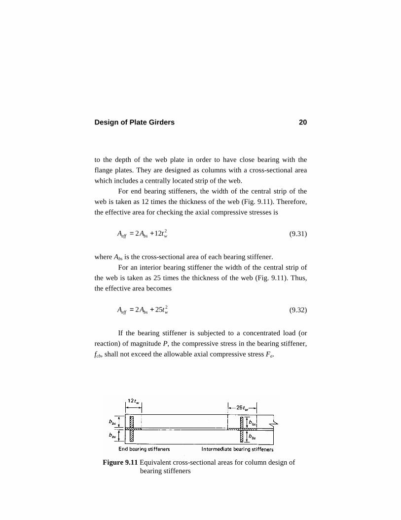
to the depth of the web plate in order to have close bearing with the flange plates. They are designed as columns with a cross-sectional area which includes a centrally located strip of the web. For end bearing stiffeners, the width of the central strip of the web is taken as 12 times the thickness of the web (Fig. 9.11). Therefore, the effective area for checking the axial compressive stresses is 2122 wbseff tAA += (9.31)
where Abs is the cross-sectional area of each bearing stiffener.
For an interior bearing stiffener the width of the central strip of the web is taken as 25 times the thickness of the web (Fig. 9.11). Thus, the effective area becomes 2252 wbseff tAA += (9.32)
If the bearing stiffener is subjected to a concentrated load (or reaction) of magnitude P, the compressive stress in the bearing stiffener, fcb, shall not exceed the allowable axial compressive stress Fa.
Figure 9.11 Equivalent cross-sectional areas for column design of bearing stiffeners
Design of Plate Girders 21
a
effcb F
APf ≤= (9.33)
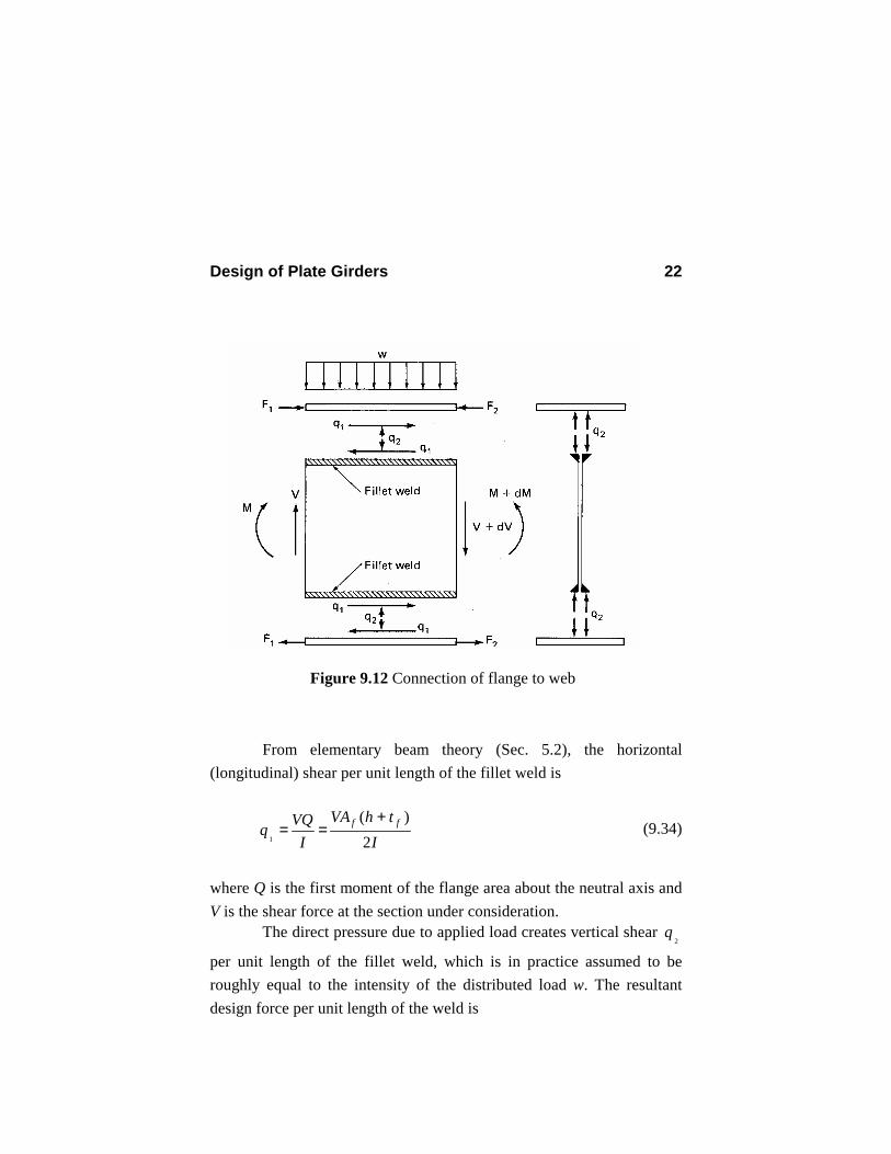
Evaluation of the allowable axial stress requires determination of the slenderness ration KL/r. Because the bearing stiffeners are connected to the web, the effective length factor K is taken as low as 0.75. Since the allowable axial compressive stress Fa depends on the radius of gyration, r, the bearing stiffeners must be designed by the trial-and-error procedure. Buckling of the web will conceivably occur about a horizontal axis parallel to the plane of the web. So it is customarily assumed that the hypothetical column consisting of the web and stiffeners will possibly buckle about the same axis; otherwise each stiffener will buckle about its own axis, which is perpendicular to the previously mentioned axis. As a result, the radius of gyration r is calculated about the horizontal axis in the plane of the web. 9.7 DESIGN OF WELDED CONNECTIONS 9.7.1 Connection of Flange to Web Flange and web plates are connected to each other by fillet welds. Figure 9.12 shows a disassembled portion of the plate girder between two neighboring sections. Flange-to-web fillet welds are designed to transmit horizontal shear due to the variation of the bending moment over the girder and the direct pressure due to applied distributed load.
Design of Plate Girders 22
From elementary beam theory (Sec. 5.2), the horizontal (longitudinal) shear per unit length of the fillet weld is
IthVA
IVQq ff
2)(
1
+== (9.34)
where Q is the first moment of the flange area about the neutral axis and V is the shear force at the section under consideration. The direct pressure due to applied load creates vertical shear
2q
per unit length of the fillet weld, which is in practice assumed to be roughly equal to the intensity of the distributed load w. The resultant design force per unit length of the weld is
Figure 9.12 Connection of flange to web
Design of Plate Girders 23
2/122 )(21
qqq += (9.35)
If we denote the size of the fillet weld by ww and the allowable shear stress of the weld electrode by Fv, noting that there are two lines of fillet welds on each side of the web plate, the allowable strength of the fillet weld will be vwa Fwq )2)(707.0(= (for SMAW) (9.36) Substituting for value of
1q , from Eq. (9.36), and
2q = w into Eq. (9.35)
and equating the resulting equation to Eq. (9.36), we obtain the following equation for the size of the continuous fillet weld:
v
ff
w F
wthIAV
w414.1
)(4
2/1
222
22
++
= (for SMAW) (9.37)
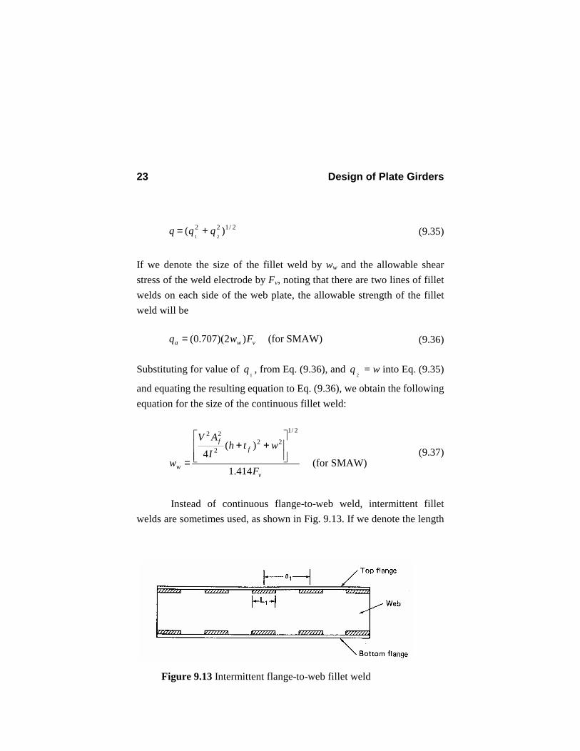
Instead of continuous flange-to-web weld, intermittent fillet welds are sometimes used, as shown in Fig. 9.13. If we denote the length
Figure 9.13 Intermittent flange-to-web fillet weld
Design of Plate Girders 24
of each portion of the fillet weld by L1 and the spacing of the intermittent weld by a1, the following relation holds between these two variables: qaqL a 11 = (9.38) Substituting for q and qa form Eqs. (9.35) and (9.36), respectively, we obtain
v
ff
w
F
wthIAV
awL
414.1
)(4
2/1
222
22
1
1
++
= (for SMAW) (9.39)
By choosing two of the three parameters a1, L1, and ww, the designer can find the third parameter from Eq. (9.39). 9.7.2 Connection of Intermediate Stiffeners to the Web The magnitude of the shear transfer between the web and stiffeners is in general very small. As a result, a minimum amount of welding is used. When the tension-field action is the design basis [Eq. (9.12)], however, a conservative formula is provided by the ASD code for the amount of shear to be transferred between the web and stiffeners. According to ASD G4, the connection of the intermediate stiffeners to the web plate should be designed for a total shear transfer, in Kips per linear inch of single stiffener or a pair of stiffeners, at least equal to
v
vyvs F
fFhf
2/3
340
= (9.40)
Design of Plate Girders 25
where Fy is the yield stress of the web steel in ksi, and fv and Fv are the maximum computed shear stress and the allowable shear stress in the adjacent panels, respectively. Furthermore, welds in stiffeners which are required to transmit a concentrated load or reaction should be designed for the larger of the corresponding load (or reaction) and the shear given by Eq. (9.40). If intermediate stiffeners are used in pairs, noting there are four lines of fillet weld at each stiffener-web connection, we find that the required continuous weld size is
v
vs
v
vsw F
fF
fw828.2707.0
4/== (for SMAW) (9.41)
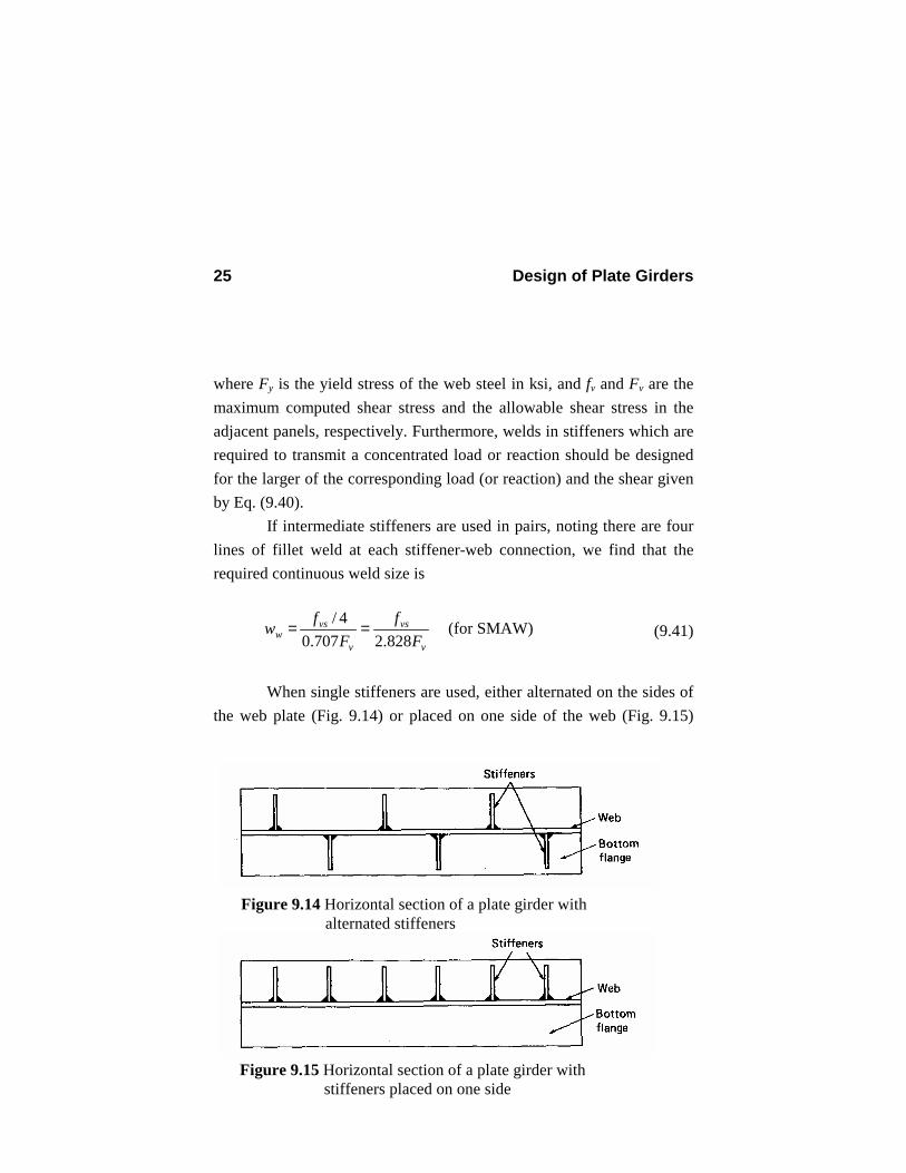
When single stiffeners are used, either alternated on the sides of the web plate (Fig. 9.14) or placed on one side of the web (Fig. 9.15)
Figure 9.14 Horizontal section of a plate girder with alternated stiffeners
Figure 9.15 Horizontal section of a plate girder with stiffeners placed on one side
Design of Plate Girders 26
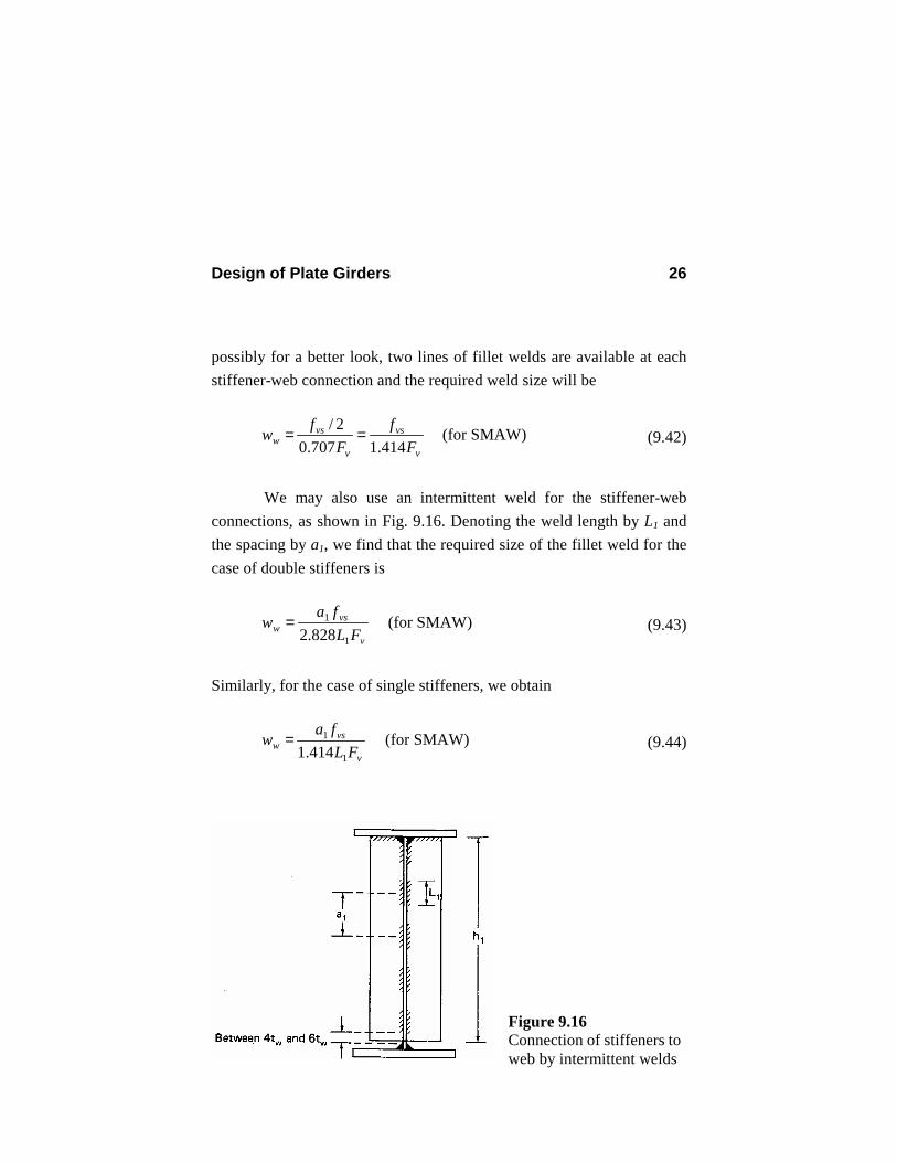
possibly for a better look, two lines of fillet welds are available at each stiffener-web connection and the required weld size will be
v
vs
v
vsw F
fF
fw414.1707.0
2/== (for SMAW) (9.42)
We may also use an intermittent weld for the stiffener-web connections, as shown in Fig. 9.16. Denoting the weld length by L1 and the spacing by a1, we find that the required size of the fillet weld for the case of double stiffeners is
v
vsw FL
faw
1
1
828.2= (for SMAW) (9.43)
Similarly, for the case of single stiffeners, we obtain
v
vsw FL
faw1
1
414.1= (for SMAW) (9.44)
Figure 9.16 Connection of stiffeners toweb by intermittent welds
Design of Plate Girders 27
The clear distance between welds should not be greater than 16 times the web thickness or greater than 10 inches (ASD G4). 16)( 11 wtLa ≤− and 10 in. (9.45) Welding of the stiffeners to the compression flange keeps them normal to the web and consequently makes them more stable. Moreover, such welding causes the stiffeners to resist any uplift tendency due to torsion and thus provides restraint against torsional buckling of the compression flange. Welding of the stiffeners to the tension flange is not necessary (Fig. 9.16). In fact, such welding increases the chance of fatigue or brittle failure. Intermediate stiffeners not transmitting a concentrated load or reaction can be stopped short of the tension flange (ASD G4) (Fig. 9.16). The distance between the point of termination of the stiffener-to-web weld and the near toe of the web-to-flange weld should not be smaller than four times the web thickness or greater than six times the web thickness. 9.8 DESIGN OF A SIMPLE HOMOGENEOUS PLATE GIRDER
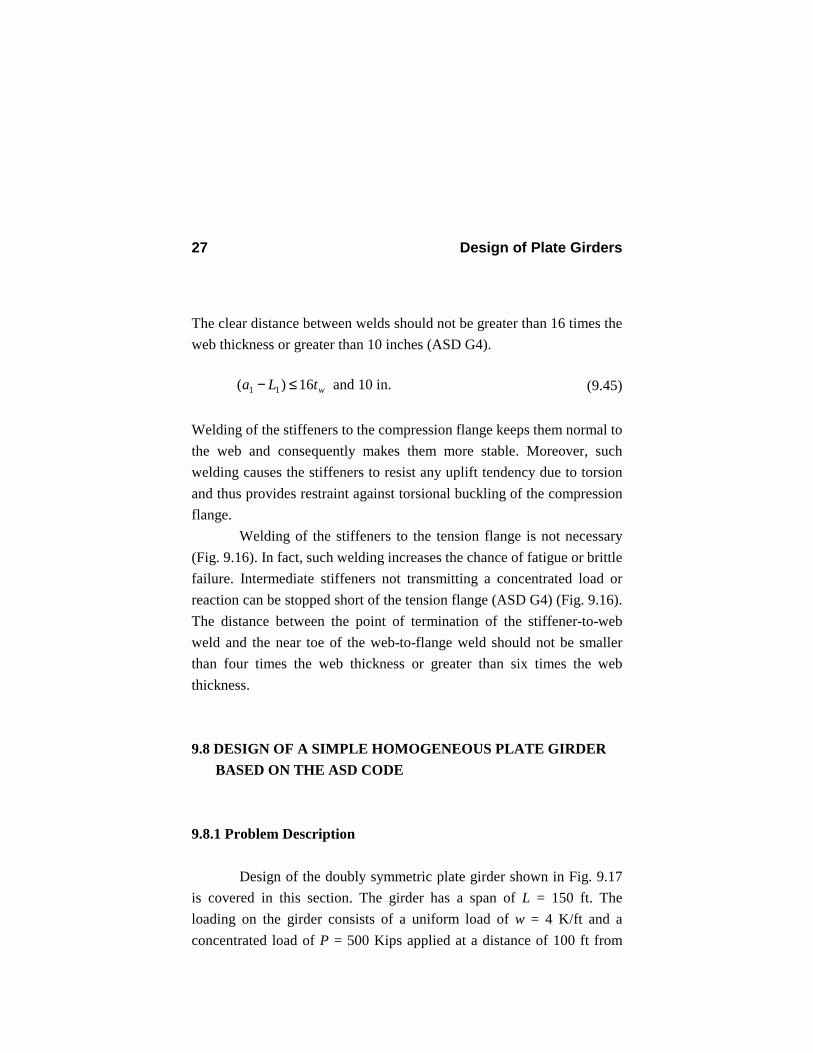
BASED ON THE ASD CODE 9.8.1 Problem Description Design of the doubly symmetric plate girder shown in Fig. 9.17 is covered in this section. The girder has a span of L = 150 ft. The loading on the girder consists of a uniform load of w = 4 K/ft and a concentrated load of P = 500 Kips applied at a distance of 100 ft from
Design of Plate Girders 28
the left support. Use A36 steel with yield stress of 36 ksi for the flange and web plates as well as the double stiffeners. For welds, use E70 electrodes with an allowable shear stress of 21 ksi. Lateral support is provided at supports, at the point of application of concentrated load, and at point D located at a distance of 50 ft from the left support A. Since the compression flange carries a uniform load, assume that it is restrained against rotation.
9.8.2 Shear and Bending Moment Diagrams Reactions at support A and B (Fig. 9.17) are
67.466150
(500)(50)5)(4)(150)(7 =+=AR Kips
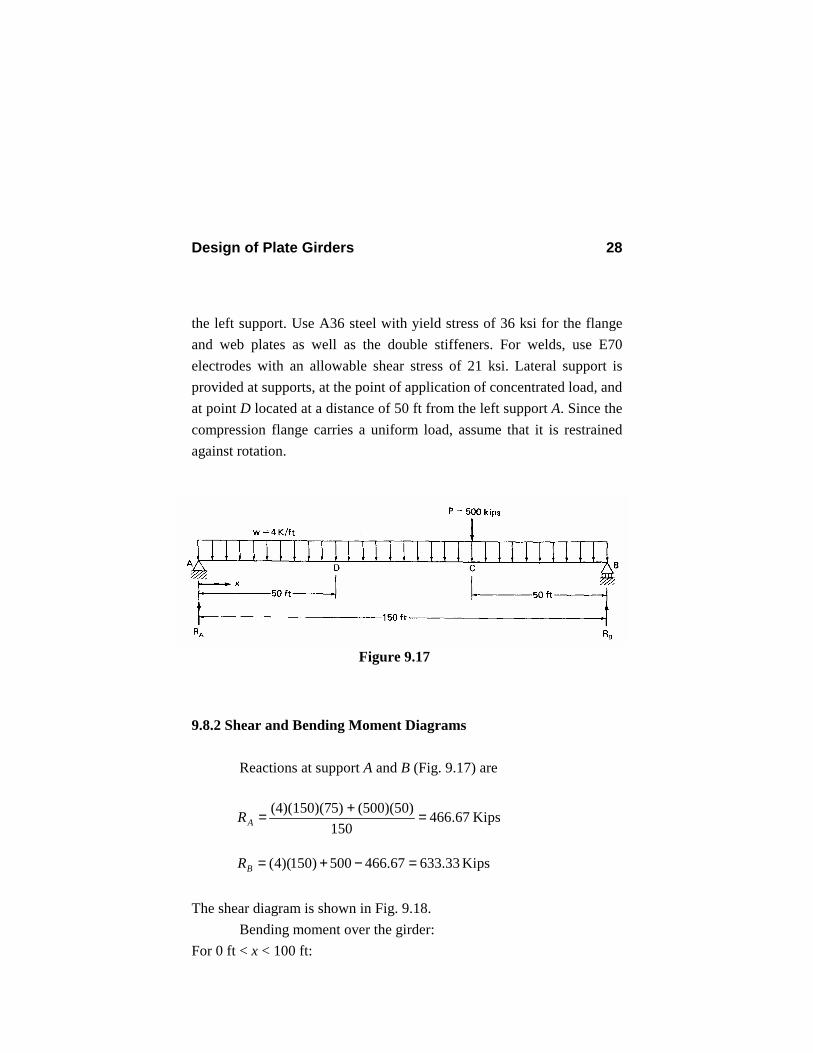
33.63367.466500)150)(4( =−+=BR Kips The shear diagram is shown in Fig. 9.18. Bending moment over the girder: For 0 ft < x < 100 ft:
Figure 9.17
Design of Plate Girders 29
2)(2wxxRxM A −=
67.1164
67.4660)(11 ===⇒=−=
wRxwxR
dxxdM A
A ft > 100 ft
∴ There is no maximum between A and C. For 100 ft < x < 150 ft: )100(2)(
2−−−= xPwxxRxM A
00)(11 <−=⇒=−−=
wPRxPwxR
dxxdM A
A
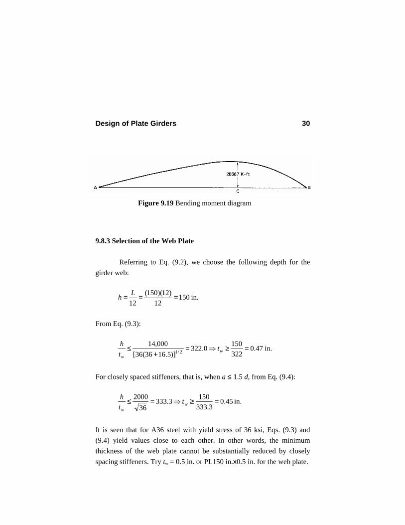
∴ There is no maximum between C and B. Therefore, the maximum bending moment over the girder is at point C under the concentrated load. Mmax = Mc = 466.67(100) - 4(100)(50) = 26667 K-ft The bending moment diagram is shown in Fig. 9.19.
Figure 9.18 Shear diagram
Design of Plate Girders 30
9.8.3 Selection of the Web Plate Referring to Eq. (9.2), we choose the following depth for the girder web:
15012
)12)(150(12
=== Lh in.
From Eq. (9.3):
47.03221500.322
)]5.1636(36[000,14
2/1 =≥⇒=+
≤ ww
tth in.
For closely spaced stiffeners, that is, when a ≤ 1.5 d, from Eq. (9.4):
45.03.333
1503.33336
2000 =≥⇒=≤ ww
tth in.
It is seen that for A36 steel with yield stress of 36 ksi, Eqs. (9.3) and (9.4) yield values close to each other. In other words, the minimum thickness of the web plate cannot be substantially reduced by closely spacing stiffeners. Try tw = 0.5 in. or PL150 in.x0.5 in. for the web plate.
Figure 9.19 Bending moment diagram
Design of Plate Girders 31
300=
wth ; 75=wA in.2
Tentatively assuming the allowable bending stress to be Fb = 0.60Fy = 22 ksi, check if reduction of the allowable bending stress is required.
67.161970300 =>=yw Ft
h
∴ Allowable bending stress must be reduced according to Eq. (9.24). 9.8.4 Selection of Flange Plates Because the allowable bending stress in the flange plates must be reduced, we may decrease Fb = 0.60Fy = 22 ksi somewhat, say, to Fb = 20 ksi. The required flange area, Af, can be computed approximately from Eq. (9.19).
17.94675
)150)(20()12)(667,26( =−== fff tbA in.2
The minimum flange thickness in order to prevent flange local
buckling is obtained from Eq. (9.22).
46.0)/(05.4
wc th
k = for 70>wth
Design of Plate Girders 32
294.0
)300(05.4
46.0 ==ck
2/1
)17.94(190
294.036
=ft = 2.34 in.
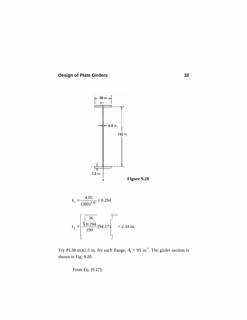
Try PL38 in.x2.5 in. for each flange; Af = 95 in.2. The girder section is shown in Fig. 9.20.
From Eq. (9.17):
Figure 9.20
Design of Plate Girders 33
4
312223
121
in. 396,245,1
)5.2)(38()25.175)(5.2)(38(2)150)(5.0(
=
+++=I
3in. 16,069.6
2.5751,245,396
2/=
+=
+=
fthIS
Find the allowable bending stress Fb (Sec. 5.5).
rT = radius of gyration of the flange plus one-sixth of the web area
about the y-axis (Fig. 9.20)
2/133
)6(126
++
=wff
wffT htbt
htbtr
2/1
2/13
)/212()6(12
6
fw
f
wff
ffT AA
b
htbt
btr
+=
+≈
(9.46)
31.10
)95/15012(38
2/1 =+
=Tr in.
For region AD and CB of the girder the ratio of the smaller to larger end moments, M1/M2, is zero (Figs. 9.17 and 9.19). This ratio for region DC is equal to M1/M2 = MD/MC = -18,333.5/26,667 = -0.687 Region DC is the critical region, so we find the allowable bending stress for this region.
Design of Plate Girders 34
Cb = 1.75 + 1.05(M1/M2)+0.3(M1/M2)2 = 1.75+1.05(-0.687)+0.3(-0.687)2 = 1.17 < 2.30
74.12836
)17.1)(000,510(000,510 2/12/1
=
=
y
b
FC
58.5736
)17.1)(000,102(000,102 2/12/1
=
=
y
b
FC
uL = unbraced length = 50=== CBDCAD ft
2/12/1000,5102.58
31.10)12)(50(000,102
<==<
y
b
T
u
y
b
FC
rL
FC
55.21)36( )17.1(000,530,1
)2.58)(36(32
000,530,1)/(
32 22
=
−=
−= y
b
Tuyb F
CrLF
F ksi
Calculate the reduced allowable bending stress F’b from Eq. (9.24).
39.2055.2155.21
7605.0
150 95750005.00.1' =
−
−=bF ksi
The maximum bending stress in the girder is
91.196.069,16
)12)(667,26(max ===S
Mfb ksi < 20.39 ksi O.K.
Design of Plate Girders 35
9.8.5 Intermediate Stiffeners 1. Check if intermediate stiffeners are required [Eq. (9.14)].
2603005.0
150 >==wth
∴ Stiffeners are required.
2. Find the location of the first stiffener from each end.
a. At the left end
22.675
67.466 ===w
Av A
Rf ksi
Substitute for Fv = fv = 6.22 ksi in Eq. (9.6) and solve for Cv.
8.05.036
)22.6)(89.2(89.2<===
y
vv F
FC
From Eq. (9.7):
34.936000,45
)300)(5.0)(36(000,45
)/( 22
>=== wvyv
thCFk
From Eq. (9.8):
Design of Plate Girders 36
2/12/1
43634.5
434.5
−=
−
=vkh
a = 0.41
amax = 0.41(150) = 61.3 in.
Tentatively, place the first intermediate stiffener at a distance of 50 in. from the left end A.
b. At the right end
44.875
33.633 ===w
Bv A
Rf ksi
8.0678.036
)44.8)(89.2(89.2<===
y
vv F
FC
34.981.48000,45
)300)(678.0)(36(000,45
)/( 22
>=== wvyv
thCFk
345.0481.48
34.54
34.5 2/12/1
=
−=
−
=vkh
a in.
amax = 0.345(150) = 51.8 in.
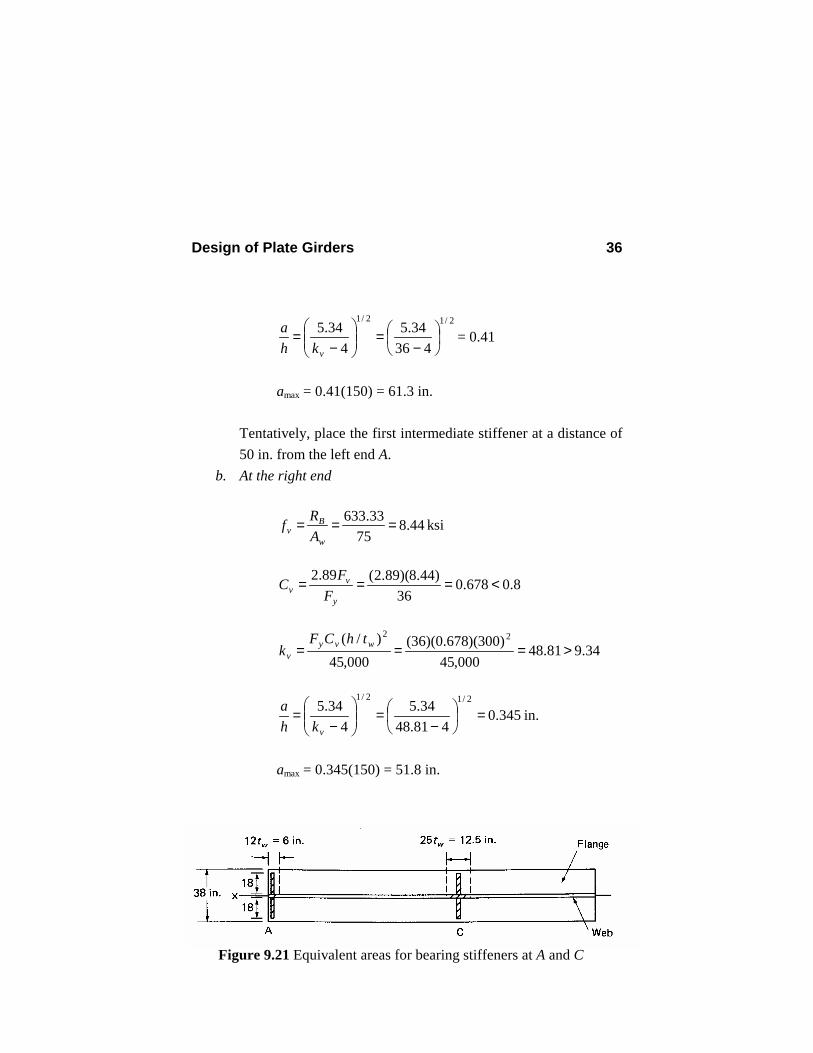
Figure 9.21 Equivalent areas for bearing stiffeners at A and C
Design of Plate Girders 37
Tentatively, place the first intermediate stiffener at a distance of 40 in. from the left end B.
3. Find the spacing of remaining stiffeners. From Eq. (9.10)
[ ] [ ] 6.112)150()300/(260)//(260
22
==≤ htha w in.
amax = 112.6 in.
Equation (9.10) controls over Eq. (9.11), so the latter need not be checked. We choose to use uniform spacing between point E (at the location of the first stiffener away from the left end) and point C (at the location of the concentrated load) and also between point C and F (at the location of the first stiffener away from the right end) (Fig. 9.22). a. Spacing of the stiffeners between points E and C (Fig. 9.22)
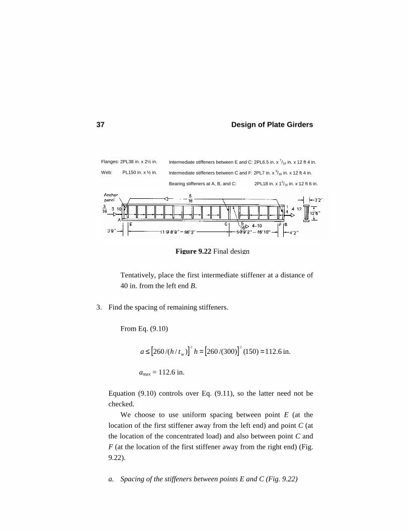
Figure 9.22 Final design
Flanges: 2PL38 in. x 2½ in. Web: PL150 in. x ½ in.
Intermediate stiffeners between E and C: 2PL6.5 in. x 7/16 in. x 12 ft 4 in. Intermediate stiffeners between C and F: 2PL7 in. x 9/16 in. x 12 ft 4 in. Bearing stiffeners at A, B, and C: 2PL18 in. x 13/16 in. x 12 ft 6 in.
Design of Plate Girders 38
maxV = maximum shear
= 0.450)4(67.466)( 1250
1250 =−=− wRA Kips
00.675
450max ===w
v AV
f ksi
Try a = 105 in. and change the spacing of the first stiffener away from end A from 50 in. to 45 in. (Fig. 9.22).
67.451)4(67.466)( 12
451245
max =−=−= wRV A Kips
02.6
7567.451max ===
wv A
Vf ksi
17.0150105 <==
ha
90.14)7.0(
34.50.4)/(
34.50.4 22 =+=+=ha
kv
8.0207.0)300)(36(
)90.14)(000,45()/(
000,4522 <===
wy
vv thF
kC
Because all five conditions mentioned in Sec. 9.3 are satisfied, we can take advantage of the tension-field action and use Eq. (9.12) for calculating the allowable shear stress.
ksi 6.02 ksi 62.904.758.2)7.01(15.1
207.01207.089.2
362/12
=>=+=
+−+=
v
v
f
F
O.K.

Design of Plate Girders 39
Note that the contribution of the tension-field action is substantial in this example.
b. Spacing of the stiffeners between points C and F (Fig. 9.22) 0.620)4(33.633)( 12
401240
max =−=−= wRV B Kips
27.8
75620max ===
wv A
Vf ksi
Try a = 110 in. and change the spacing of the first stiffener away from end B from 40 in. to 50 in. (Fig. 9.22).
66.616)4(33.633)( 12
501250
max =−=−= wRV B Kips
22.8
7566.616max ===
wv A
Vf ksi
1733.0150110 <==
ha
93.13)733.0(
34.50.4)/(
34.50.4 22 =+=+=ha
kv
8.0193.0)300)(36(
)93.13)(000,45()/(
000,4522 <===
wy
vv thF
kC
From Eq. (9.12):
Design of Plate Girders 40
ksi 8.22 ksi 45.905.740.2)733.01(15.1
193.01193.089.2
362/12
=>=+=
+−+=
v
v
f
F
O.K. Spacing of the stiffeners over the girder span is shown in Fig. 9.22.
4. Check combined shear and bending in the web.
The critical section for this check is either at point C, where the bending moment has the largest value and the shear force is considerable, or somewhere close to but to the right of this point, where the bending is slightly smaller than the maximum value but the shear force is larger than that at point C (Figs. 9.18 and 9.19).
Let us first check the combined shear and bending at point C under the concentrated load [Eq. (9.30)].
78.575
33.433 ===w
Cv A
Vf ksi
The allowable bending tensile stress in the web [Eq. (9.30)]:
44.21)36( 45.978.5375.0825.0375.0825.0 =
−=
−= y
v
vb F
Ff
F ksi
The maximum bending tensile stress in the web (at the junction of web and flange):
27.19396,245,1
)75)(12)(667,26( ===I
yMf Cb ksi < Fb = 21.44 ksi O.K.
Design of Plate Girders 41
Note that if this condition is not satisfied, the spacing of the intermediate stiffeners is normally reduced. Also, because fb/Fb = 0.90 is considerably less than one, we do not need to check the other locations to the right of point C. Whenever fb/Fb is close to one, such a check may be necessary.
5. Select the intermediate stiffeners.
Spacing of the stiffeners between E and C is a = 105 in. and between C and F is a = 110 in. (Fig. 9.22). The cross-sectional area of a pair of stiffeners is found by Eq. (9.27), which is a function of aspect ratio a/h.
a. For region EC. From Eq. (9.27):
2
2/12
2
in. 56.5
62.902.6
)7.01(7.07.0)207.01)(5.0)(150(
21
=
+−−=stA
2in. 78.22/56.5 ==sstb (9.47)
From Eq. (9.29):
8.15
3695 =≤
s
s
tb
Substituting for bs = 15.8ts in Eq. (9.47) will yield the minimum thickness required for the intermediate stiffeners.
Design of Plate Girders 42
in. 419.0)8.15/78.2( 2/1 ==st = 6.7/16 in. Try 2PL6½ in. x 7/16 in. for intermediate stiffeners from E to C (excluding C). Check the moment of inertia requirement (Eq. 9.28).
4
44
in. 8150
15050
=
=
h
( ) 443
167
121 in. 81in. 7.89)5.025.6( >=+×=stI O.K.
Use 2PL6½ in. x 7/16 in. for intermediate stiffeners from E to C (excluding C). Intermediate stiffeners need not be extended to the tension flange (Fig. 9.22) and their length h1 can be four times the web thickness shorter than the depth of the web.
148)5.0(415041 =−=−= wthh in. = 12 ft 4 in.
b. For region CF. From Eq. (9.27):
2
2/12
2
in. 89.7
45.922.8
)733.01(733.0733.0)193.01)(5.0)(150(
21
=
+−−=stA
2in. 94.32/89.7 ==sstb
ss tb 8.15=
Minimum 5.0)8.15/94.3( 2/1 ==st in.
Design of Plate Girders 43
Use 2PL7 in. x 9/16 in. for intermediate stiffeners from C to F (excluding C). Moment of inertia check is not needed, because these plates are larger than those used in region EC. Length of stiffeners:
=−= wthh 41 12 ft 4 in.
9.8.6. Bearing Stiffeners Bearing stiffeners should extend roughly to the edges of the flange plates. Noting that the width of the flange plates is 38 in. and the thickness of the web is 0.5 in., we choose a width of bbs = 18 in. for the three pairs of bearing stiffeners (Fig. 9.22). 1. Bearing stiffeners at the left support
a. Check buckling (width-thickness ratio).
8.15
369595 ==≤
ybs
bs
Ftb
in. 16
2.18in. 1.148.15
18 ==≥bst
Try 2PL18 in. x 13/16 in. for the left support. Abs = 21.375 in.2
b. Check axial compressive stress due to reaction RA = 466.67 Kips. From Eq. (9.31):
75.45)5.0(12)375.21(2122 22 =+=+= wbseff tAA in.2
Design of Plate Girders 44
Moment of inertia of the equivalent area about the x-axis (Fig. 9.21):
( ) 06.4812)5.36( 31619
121 =≈I in.4
Radius of gyration about the x-axis:
26.1075.45/06.4812/ === effAIr in.
96.1026.10
)150(75.0 ==r
KL
rKL
FEC
yc >=
=
= 1.126
36)000,29(22
2/122/1
2 ππ
F.S. = factor of safety = 3
3
8)/(
8)/(3
35
cc CrKL
CrKL −+
= 3
1.12696.10
81
1.12696.10
83
35
−
+
= 1.699 Allowable axial stress:
( )
ksi 11.21
699.136
1.12696.10
211F.S./
2/1
2
2
2
=
−=
−= y
ca F
CrKLF
Actual axial stress:
Design of Plate Girders 45
20.1075.4567.466 ===
eff
Aa A
Rf ksi < 21.11 ksi O.K.
Use 2PL18 in. x 13/16 in. x 12 ft 6 in. for the bearing stiffeners at the left support. Sometimes the height of the bearing stiffeners is chosen slightly, say ¼ in., less than the depth of the web plate. The bearing stiffener, however, should be in contact with the flange receiving the concentrated load.
2. Bearing stiffeners at the right support
Reaction at the right support:
33.633=BR Kips Try 2PL18 in. x 13/16 in. the same as for the left support.
11.21 ksi 84.13
75.4533.633 =<=== a
eff
Ba F
ARf ksi O.K.
Use 2PL18 in. x 13/16 in. x 12 ft 6 in. for the bearing stiffeners at the right support.
3. Bearing stiffeners at the concentrated load
Because the axial load for these stiffeners, P = 500 Kips, is less than RB, and the effective area (Fig. 9.21) is larger than that of the end
Design of Plate Girders 46
bearing stiffeners, we can use the same 2PL18 in. x 13/16 in. x 12 ft 6 in. for bearing stiffeners at the location of the concentrated load.
9.8.7 Web-to-Flange Fillet Weld We design the web-to-flange connection based on the maximum shear over the girder length.
33.633max == BRV Kips
We use intermittent SMAW welds. The relation between the width of the fillet weld ww, the length of weld segment L1, and the spacing a1 is given by Eq. (9.39).
1246.0)21(414.1
124)5.2150(
)396,245,1(4)95()33.633(
2/122
2
22
1
1 =
++
=awL w
Minimum weld size for a 2.5-in. flange plate is 5/16 in. (Sec. 8.3.5 and ASD Table J2.4). Try ww = 5/16 in. Substituting this value into the previous equation, we obtain
11 51.2 La = (9.48) The minimum length of a segment of intermittent weld is larger of four times the weld size (4ww = 1.25 in.) and 1.5 in. (ASD J2b).
5.1min1 =L in.
Design of Plate Girders 47
The maximum longitudinal spacing of the intermittent weld is the smaller of 24 times the thickness of the thinner plate and 12 in. (ASD D2).
Thickness of the thinner plate = 0.5 in.
12max =a in. Try 5/16-in. weld, 4 in. long. From Eq. (9.48), we obtain 04.101 =a in. Use 5/16-in. weld, 4 in. long, 10-in. spacing. 9.8.8. Stiffener-to-Web Fillet Weld 1. For segment EC (Fig. 9.22) 02.6=vf ksi; 62.9=vF ksi
From Eq. (9.40):
23.362.902.6
34036)150(
340
2/32/3
=
=
=
v
vyvs F
fFhf ksi
We use intermittent welds. From Eq. (9.43):
Design of Plate Girders 48
05439.0
)21(828.223.3
828.21
1 ===v
vsw
Ff
awL
(9.49)
The minimum weld size for a ½-in.-thick plate is 3/16 in. The maximum weld spacing is
sta 24max = or 12 in. = ( )16724 = 10.5 in.
Try a 3/16-in. fillet weld with a spacing of 10 in. From Eq. (9.49) we obtain L1 = 2.90 in. Minimum length of the weld segment = 4ww or 1.5 in. = 1.5 in. Use 3/16-in. weld, 3.0 in. long, 10-in. spacing.
2. For segment CF (Fig. 9.22) =vf 8.22 ksi; =vF 9.45 ksi
5.445.922.8
34036)150(
2/3
=
=vsf ksi
0757.0)21(828.2
50.4
1
1 ==awL w (9.50)
The minimum weld size for a 9/16-in.-thick plate is ¼ in.
=maxa 12 in.
=min1L 1.5 in.
Design of Plate Girders 49
Try a ¼-in. intermittent fillet weld with a spacing of a1 = 12 in. From Eq. (9.50) we obtain L1 = 3.63 in. Use ¼-in. weld, 4 in. long, 12-in. spacing.
3. Bearing stiffeners
We use 2PL18 in. x 13/16 in. x 12 ft 6 in. for each pair of bearing stiffeners. Minimum weld size: 5/16 in. Try ww = 5/16 in. Use continuous welds on both sides of each stiffener plate.
Shear strength of 5/16-in. fillet weld = ( ) )21(707.0 16
5 = 4.64 K/in.
Total strength of four lines of weld = 4(150)(4.64) = 2784 Kips
33.633max =>V Kips O.K.
and
675)50.4)(150( ==> vshf Kips O.K.
Use 5/16-in. weld continuously on both sides of all bearing stiffeners.
9.8.9. Girder Weight γ = specific gravity of steel = 0.490 Kips/ft3 Weight of the flange plates = 2Af Lγ = 2( 144
95 )(150)(0.49) = 96.89 Kips
Design of Plate Girders 50
Weight of the web plates = htwLγ = ( 12150 )( 12
5.0 )(150)(0.49) = 38.28 Kips
Weight of the flange and web plates = 135.26 Kips Weight of the stiffeners = [3(2)(18)( 16
19 )(150) + 11(2)(6.5)( 167 )(148.0)
+ 5(2)(7)( 169 )(148.0)](0.49/123) = 9.73 Kips
Total weight of the plate girder = 135.26 + 9.73 = 145.0 Kips Note that the weight of the stiffeners is 6.7 percent of the total weight of the plate girder. 9.9 DESIGN OF A HYBRID GIRDER BASED ON THE ASD
CODE 9.9.1 Problem Description Design of the same plate girder described in Sec. 9.8.1 is desired except that 1. The yield stress of steel used in the flange is 50 ksi (the yield stress
of the web plate and stiffeners is the same, 36 ksi). 2. The compression flange is laterally supported throughout its length. 3. Single intermediate stiffeners are used. The shear and bending moment diagrams are the same as before (Figs. 9.18 and 9.19). 9.9.2. Selection of the Web Plate
Design of Plate Girders 51
Depth of the girder web: h = L/12 = 150 in. From Eq. (9.3):
62.08.242
1508.242)]5.1650(50[
000,142/1 =≥⇒=
+≤ w
wt
th in.
For closely spaced stiffeners, i.e., when a ≤ 1.5d, from Eq. (9.4):
53.08.282
1508.28250
2000 =≥⇒=≤ ww
tth in.
Try tw = 9/16 in. or PL150 in. x 9/16 in. for the web plate. Note that spacing of the intermediate stiffeners a should not be greater than 1.5d. For the selected web plate, we have
67.2663
800 ==wth ; ( ) 375.84)150( 16
9 ==wA in.2
67.26618.13750
970970 =<==wy th
F
The allowable bending stress must be reduced according to Eq. (9.24). 9.9.3 Selection of Flange Plates First, we find an approximate relation for the area of one flange plate for hybrid girders, taking into account the reduction of the
Design of Plate Girders 52
allowable bending stress according to Eq. (9.24). This equation at the limit can be written as (neglecting the term in the bracket)
bwf
wfb F
AAAA
F++
=6
6' β (9.51)
where 35.05.1 ααβ −= (9.52)
From Eq. (9.18):
)6(6'
maxwf
b
AAhF
MS +== (9.53)
Combining Eqs. (9.51) and (9.53) and solving Af, we obtain
6max w
bf
AhF
MA β−= (9.54)
In this example: 0.172.030/)36(6.0/60.0 <=== byw FFα
893.0)72.0(5.0)72.0(5.1 3 =−=β
55.586
)375.84)(893.0()150)(50)(60.0(
)12)(667,26( =−=fA in.2
Minimum flange thickness is found from Eq. (9.22).
Design of Plate Girders 53
310.0
)67.266(05.4
)/(05.4
46.046.0 ===th
kc
2/1
)55.58(190
31.0/50
=ft = 1.98 in.
Try PL30 in. x 2 in. for each flange plate; Af = 60 in.2 Check Eq. (9.20):
0.1531.0/50
190/
1900.152
30 =====cyff
f
kFtb
Properties of the section:
( ) ( ) 423
1223
169
121 in. 363,851)175( )60(2)2( 30)150( =+++=I
3in. 7.056,11
275851,363
2/=
+=
+=
fthIS
Allowable bending stress Fb = 0.60Fyf = 0.60(50) = 30 ksi We find the reduced allowable bending stress from Eq. (9.24):
406.10.60
375.84 ==f
w
AA
980.0406.16
)406.1(893.06/6/6
=+
+=++
=fw
fwe AA
AAR
β
Design of Plate Girders 54
( )
ksi 76.26
)980.0(76.13867.2660.60
375.84)0005.0(0.1)30('
=
−
−=bF
94.287.056,11
)12)(667,26(max ===S
Mfb ksi > 26.76 ksi N.G.
Try PL31 in. x 21/8 in. for each flange. 875.65)125.2)(31( ==fA in.2 ( ) ( )
4
216173
1223
169
121
in. 8.492,920
)75)(125.2( )31(2)125.2( 31)150(
=
+++=I
3
817
in. 1.935,1175
920,492.8 =+
=S
Check Eq. (9.20):
0.15/
19059.14231
81
=<==cyff
f
kFtb
O.K.
Calculate the reduced allowable bending stress from Eq. (9.24).
281.1)125.2)(31(
375.84 ==f
w
AA
981.0281.16
)281.1(893.06/6/6
=+
+=++
=fw
fwe AA
AAR
β
Design of Plate Girders 55
( )
ksi 02.27
)981.0(76.13867.266875.65375.84)0005.0(0.1)30('
=
−
−=bF
81.261.935,11
)12)(667,26(max ===S
Mfb ksi < '
bF O.K.
Use PL31 in. x 21/8 in. for each flange. Af = 65.875 in.2 9.9.4 Intermediate Stiffeners Intermediate stiffeners are required, and their spacing should not be greater than amax = 1.5d = 1.5(h + 2tf) = 1.5(150 + 4.25) = 231.4 in. Also, from Eq. (9.10): [ ] [ ] 60.142)150(67.266/260)//(260
22
max ==≤ htha w in. (governs) For hybrid girders, the design cannot be based on tension-field action, and we must use Eq. (9.6) for the allowable shear stress. We use uniform spacing between A and C and between C and B (Fig. 9.17). 1. Spacing of the stiffeners between A and C.
40.140.40 ksi 53.5375.84
67.466max =<==== yw
A
wv F
AR
AV
f ksi
Design of Plate Girders 56
From Eq. (9.6):
8.0444.036
)53.5)(89.2(89.2<===
y
vv F
FC
From Eq. (9.7):
34.926.25000,45
)67.266)(444.0)(36(000,45
)/( 22
>=== wvy thCFk
From Eq. (9.8):
2/12/1
426.2534.5
434.5
−=
−=
kha = 0.501
amax = 0.501(150) = 75.2 in.
Use a = 75 in. between A and C (Fig. 9.23).
2. Spacing of the stiffeners between C and B.
40.140.40 ksi 51.7375.84
33.633max =<==== yw
B
wv F
AR
AV
f ksi
8.0603.036
)51.7)(89.2(89.2<===
y
vv F
FC
34.930.34000,45
)67.266)(603.0)(36(000,45
)/( 22
>=== wvy thCFk
Design of Plate Girders 57
42.0
430.3434.5
434.5 2/12/1
=
−=
−=
kha
amax = 0.42(150) = 63 in.
Use a = 60 in. between C and B (Fig. 9.23). Note that because the design of hybrid girders in not based on
tension-field action, no stress reduction due to interaction of simultaneous bending and shear stresses is necessary. In other words, the combined shear and bending check [Eq. (9.30)] is not required for hybrid girders.
3. Selection of intermediate stiffeners.
Selection of the size of the intermediate stiffeners in hybrid girders is based upon Eqs. (9.28) and (9.29). We can find an approximate formula for the minimum required thickness of the stiffeners. First, let us consider the case of single stiffeners. The moment of inertia of a single stiffener with respect to an axis in the plane of the web and perpendicular to the plane of the stiffeners is approximately equal to
3
31
ssst btI ≈ (9.55)
Design of Plate Girders 58
Substituting for bs from the limiting case of Eq. (9.29) into Eq. (9.55) yields
4
2/3)(792,285
sy
st tF
I = (9.56)
Finally, equating Eqs. (9.28) and (9.56) and solving for ts, we obtain the following approximate formula for the minimum required thickness of the intermediate stiffeners:
375.0)(000865.0 ys Fht = (9.57)
In the case of double stiffeners, we must multiply the right-hand side of Eqs. (9.55) and (9.56) by 2, and the resulting equation for the minimum thickness is
375.0)(000727.0 ys Fht = (9.58)
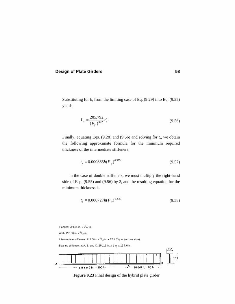
Figure 9.23 Final design of the hybrid plate girder
Flanges: 2PL31 in. x 21/8 in. Web: PL150 in. x 9/16 in. Intermediate stiffeners: PL7.5 in. x 9/16 in. x 12 ft 33/4 in. (on one side) Bearing stiffeners at A, B, and C: 2PL15 in. x 1 in. x 12 ft 6 in.
Design of Plate Girders 59
If we assume single stiffeners, the minimum stiffener thickness is
50.0)36)(150(000865.0 375.0 ==st in.
Try ts = 9/16 in. From Eq. (9.29):
90.8
36)16/9(9595
==≤y
ss
Ft
b in.
Try PL7.5 in. x 9/16 in. for stiffeners on one side.
43
3
in. 3.883295.7
169
31
231 Furnished
=
+
=
+= wssst
tbtI
4444
in. 3.88in. 8150
15050
Required <=
=
= hI st O.K.
Length of intermediate stiffeners:
75.147169415041 =
−=−= wthh in. = 12 ft 33/4 in.
Use PL7.5 in. x 9/16 in. x 12 ft 3¾ in. for stiffeners on one side.
9.9.5 Bearing Stiffeners
Design of Plate Girders 60
The procedure for design of bearing stiffeners is the same for the nonhybrid girder example of Sec. 9.8.6 and therefore will not be repeated here. The answer: Use 2PL15 in. x 1 in. x 12 ft 6 in. for bearing stiffeners at each support and at the location of the concentrated load. 9.9.6. Connections The procedure for design of web-to-flange fillet welds is the same as for nonhybrid plate girders. This portion of the design is left as an exercise for the student. For stiffener-to-web fillet welds, however, Eq. (9.40) will not apply and only the minimum amount of welding, as given in ASD J2.2b and covered in Sec. 8.3, needs to be used. 9.9.7 Girder Weight Weight of the flange plates = 2Af L γ = 2(65.875)(150)(0.49)/144 = 67.25 Kips Weight of the web plates = htwLγ = 2(150)( 16
19 )(0.49)/144 = 43.07 Kips
Weight of the flange and web plates = 67.25 + 43.07 = 110.32 Kips Weight of the stiffeners = [2(3)(1)(15)(150) + (24)( 16
9 )(7.5)(147.75)](0.49/123)
= 8.07 Kips Total weight of the plate girder = 110.32 + 8.07 = 118.39 Kips
Design of Plate Girders 61
9.10 ADDITIONAL EXAMPLES OF DESIGN OF PLATE GIRDERS ACCORDING TO THE ASD CODE
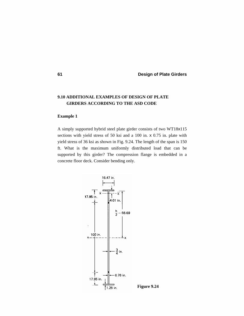
Example 1 A simply supported hybrid steel plate girder consists of two WT18x115 sections with yield stress of 50 ksi and a 100 in. x 0.75 in. plate with yield stress of 36 ksi as shown in Fig. 9.24. The length of the span is 150 ft. What is the maximum uniformly distributed load that can be supported by this girder? The compression flange is embedded in a concrete floor deck. Consider bending only.
Figure 9.24
Design of Plate Girders 62
Solution The centroidal axis of the top WT section is specified by the axis x in Fig. 9.24. Properties of a WT18x115 section are in. 26.1=ft
in. 760.0=wt
2in. 8.33=A 4in. 934=xI Moment of inertia of the built-up section:
4
31212
in. 739,340
)100)(75.0(])01.495.1750(8.33934[2
=
+−++=xI
Section modulus of the built-up section: 3in. 5.5014
67.95340,739
95.1750==
+= x
xI
S
Allowable bending stress: 30)50(60.060.0 === yfb FF ksi
18.13750
9709708.17775.0
)69.66(2 ==>==yw Ft
h
∴ Reduction of allowable bending stress in the compression flange is necessary (see Sec. 9.4.3).
Design of Plate Girders 63
75.20)26.1)(47.16( ==fA in.2
1.101)75.208.33(2))(100( 4
3 =−+=wA in.2
α= 0.60Fyw /Fb = 36/50 = 0.72
( )
( ) 0.952)75.20/()1.101(212
72.072.03)75.20/1.101(12
)/(2123)/(12
3
3
=
+
−×+=
+−+
=fw
fwe AA
AAR
αα
ksi 84.25)952.0( 30
76075.038.133
75.201.1010005.00.130
7600005.00.1'
=
−
−=
−−= e
bwf
wbb R
Fth
AA
FF
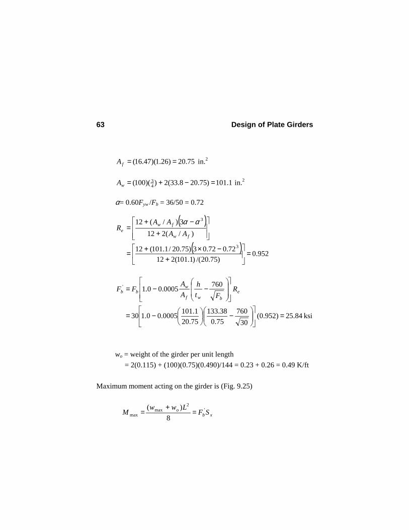
wo = weight of the girder per unit length
= 2(0.115) + (100)(0.75)(0.490)/144 = 0.23 + 0.26 = 0.49 K/ft Maximum moment acting on the girder is (Fig. 9.25)
xbo SF
LwwM '
2max
max 8)(
=+
=
Design of Plate Girders 64
Therefore, the maximum uniformly distributed load that can be supported by this girder is
35.349.0)12()150(
)5.5014)(84.25(8822
'
max =−=−= oxb w
LSF
w Kips/ft
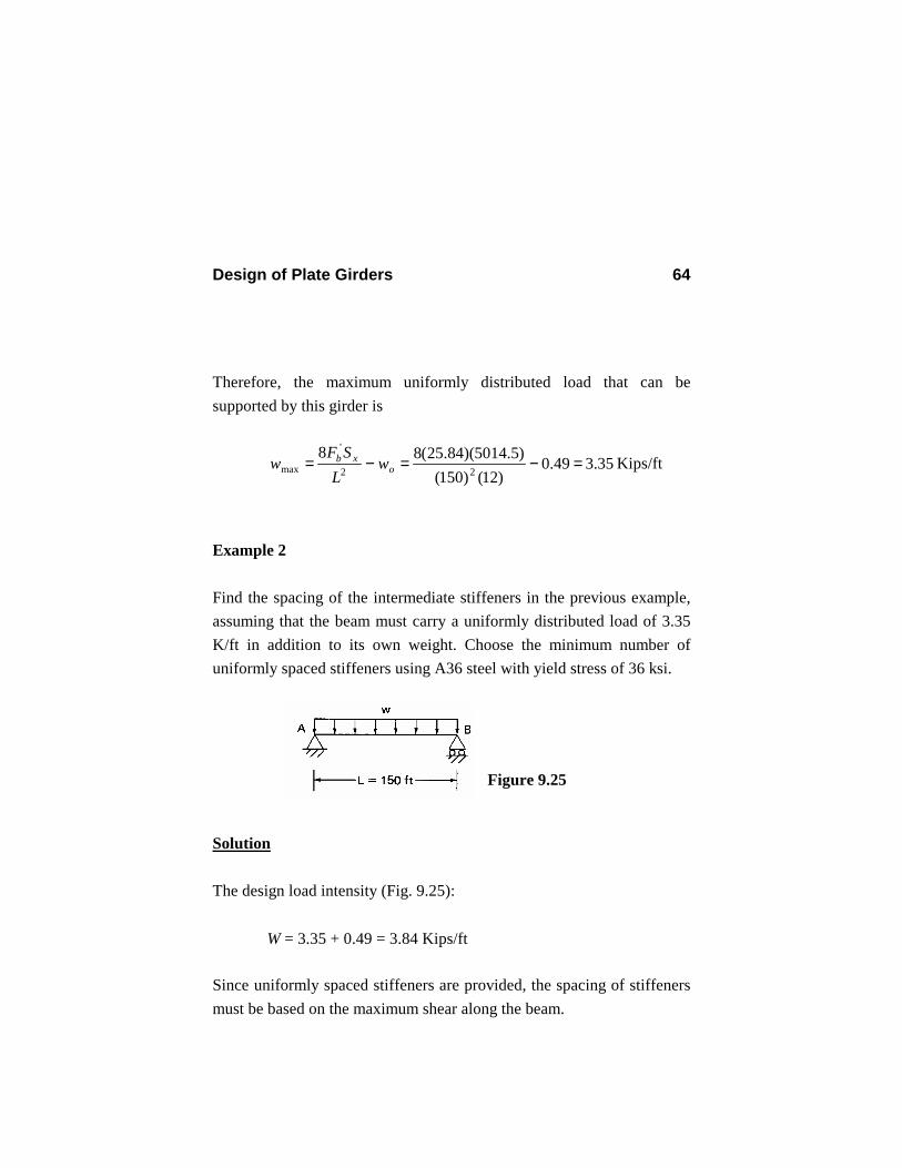
Example 2 Find the spacing of the intermediate stiffeners in the previous example, assuming that the beam must carry a uniformly distributed load of 3.35 K/ft in addition to its own weight. Choose the minimum number of uniformly spaced stiffeners using A36 steel with yield stress of 36 ksi.
Solution The design load intensity (Fig. 9.25): W = 3.35 + 0.49 = 3.84 Kips/ft Since uniformly spaced stiffeners are provided, the spacing of stiffeners must be based on the maximum shear along the beam.
Figure 9.25
Design of Plate Girders 65
288
2)150)(84.3(
2max === wLV Kips
The maximum shear stress in the girder is
4.140.40 ksi 85.21.101
288max =<=== yw
v FA
Vf ksi
We set this maximum shear stress to allowable shear stress given by Eq. (9.6) and solve for Cv.
vvy
v fCF
F ==89.2
0.800.22936
)85.2)(89.2(89.2<===
y
vv F
fC
Calculate k from Eq. (9.7).
34.979.5000,45
)8.177)(229.0)(36(000,45
)/( 22
<=== wvy thCFk
Now, we can calculate the maximum spacing from Eq. (9.8). 2/12/1
34.579.54
34.54
−=
−=
kha = 2.98
Spacing of the stiffeners is also limited by Eqs. (9.10) and (9.11). 5.397)69.66)(2(98.298.2max === ha in. = 33.1 ft
Design of Plate Girders 66
and
22.285)38.133(8.177
260/
260 22
max =
=
= h
tha
win. = 23.77 ft
Therefore, the governing limit is amax = 23.77 ft. Use
1.2577
)12)(150( ==a in.
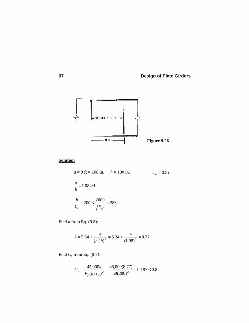
Use six intermediate stiffeners and two pairs of bearing stiffeners at the supports. Example 3 Determine the allowable shear capacity (Kips) of the homogeneous plate girder interior panel shown in fig. 9.26 if the bending tensile stress in the web is 27.5 ksi. What percentage of the shear capacity of the panel comes from the beam action prior to the web buckling and what percentage is the share of the tension-field action after the shear buckling of the web? Yield stress of the steel is 50 ksi
Design of Plate Girders 67
Solution a = 9 ft = 108 in.
h = 100 in. in. 5.0=wt
108.1 >=
ha
2832000200 =<=yfw Ft
h
Find k from Eq. (9.8):
77.8)08.1(
434.5)/(
434.5 22 =+=+=ha
k
Find Cv from Eq. (9.7):
8.0197.0)200(50
)77.8(000,45)/(
000,4522 <===
wyv thF
kC
Figure 9.26
Design of Plate Girders 68
Find the allowable shear stress from Eq. (9.12). (All of the five conditions given in Sec. 9.3 for relying on the postbuckling behavior and tension-field action of the web plate are met.)
yy
yyv
vy
v
FF
FFha
CC
FF
0.40 ksi 61.11232.0
164.0068.0)/(115.1
189.2 2
<==
+=
+
−+=
Allowable bending stress:
yyv
vb FF
Ff
F 0.55 ksi 5.27375.0825.0 ==
−=
Solve for fv: 51.8)61.11(733.0733.0 === vv Ff ksi Shear capacity of the plate girder = fv Aw = (8.51)(100)(0.5) = 425.7 Kips Percentage of the shear capacity from the beam action
percent 40
4.051.8/)50(068.0/068.0)/(89.2
=
===
= vywvwyv fFAfAF
C
Percentage of the shear capacity from the tension-field action = 100 – 40 = 60 percent
Design of Plate Girders 69
9.11 LOAD AND RESISTANCE FACTOR DESIGN OF PLATE GIRDERS
9.11.1 Introduction In this section we cover the load and resistance factor design of plate girders with tension-field action according to the LRFD code (AISC, 1998). Design of plate girders according to the LRFD code can be based on tension-field action if
ryfw Ft
h λ=> 970 (9.59)
If this requirement is not satisfied, the plate girder is designed as a beam as presented in section 5.10. In particular, when the design is without the tension-field action, the design shear strength and the transverse stiffeners will be based on the provisions of LRFD F2 covered in section 5.10.2 and LRFD Appendix F2. 9.11.2 Web Buckling Strength The following requirement must be satisfied in order to maintain sufficient web buckling strength (LRFD Appendix G1):
2/1)]5.16([000,14+yfyf FF
for a > 1.5 h
=wth
yfF000,2 for a ≤ 1.5 h
(9.60)
Design of Plate Girders 70
where h is the clear distance between flanges for welded plate girders. Note that these equations are similar to Eq. (9.3) and (9.4) for the ASD code. 9.11.3 Flexural Design The limit states to be considered in the design are tension-flange yield and compression flange buckling. If we denote the nominal flexural strength of the girder by Mn and the bending resistance factor by φb, the design flexural strength will be φb Mn. The nominal flexural strength should be taken as the smaller value obtained from the limit states of the tension-flange yield and compression flange buckling. At the present time a constant value of 0.9 is used for the resistance factor φb. 1. Limit state of tension-flange yield. The nominal flexural strength
based on the limit state of tension-flange yield is given by (LRFD Appendix G2)
ytxten FSRM = (9.61)
Coefficient Re in Eq. (9.61) is the hybrid girder factor. It is equal to 1 for nonhybrid girders and is given by
0.1212
)3(12 3
≤+
−+=
r
re a
mmaR (9.62)
Design of Plate Girders 71
for hybrid girders where ar is the ratio of the web area to the compression flange area )10/( ≤= fwr AAa and m is the ratio of the
web yield stress to the flange yield stress (m = Fyw/Fyf) or to Fcr. In Eq. (9.6), Sxt is the section modulus of the girder corresponding to the tension flange in in.3 and Fyt is the yield stress of the tension flange in ksi.
2. Limit states of compression-flange buckling. The nominal flexural strength based on the limit states of compression-flange buckling is given by (LRFD Appendix G2)
crxcePGn FSRRM = (9.63)
where Sxc is the section modulus of the girder corresponding to the compression flange in in.3. The coefficient RPG takes care of the reduction of the allowable bending stress resulting from the lateral displacement of the web plate on its compression side and is determined by
0.19703001200
1 ≤
−
+−=
crw
c
r
rPG
Fth
aa
R (9.64)
where hc is twice the distance from the neutral axis to the inside face of the compression flange and Fcr is the critical compression flange stress to be discussed later in this section. Note that Eq. (9.64) corresponds to Eq. (9.24) of the ASD code covered in Sec. 9.4.3. In general, there exist three limit states of buckling. They are lateral-torsional buckling (LTB), flange local buckling (FLB), and web local buckling (WLB). Because the design is based on the postbuckling behavior of the web plate, the limit state of WLB does
Design of Plate Girders 72
not apply. However, we must evaluate the critical Fcr corresponding to the limit states of LTB and FLB and use the lower value in Eq. (9.63).
3. Evaluation of critical stress Fcr. The critical stress Fcr is given as a
function of slenderness parameters λ, λp, and λr, and a plate girder coefficient CPG. λp and λr are the limiting slenderness parameters as defined in section 5.10.1 for beams.
yfF for λ ≤ λP
yfpr
pyfb FFC ≤
−−
−λλλλ
211 for λP <λ ≤ λr =crF
2λPGC
for λ > λr
(9.65)
The quantities λ, λp, λr, and CPG are specified for two limit states of LTB and FLB separately. a. For the limit state of LTB:
T
u
rL
=λ
(9.66)
yfp
F300=λ
(9.67)
yfr
F756=λ
(9.68)
bPG CC 000,286= (9.69)
Design of Plate Girders 73
In these equations, Cb is the same as that defined by Eq. (5.35).
b. For the limit state of FLB:
f
f
tb2
=λ
(9.70)
yfp
F65=λ
(9.71)
cyfr
kF /230=λ
(9.72)
wc th
k/4= 763.035.0 ≤≤ ck
(9.73)
cPG kC 26200=
(9.74)
0.1=bC (9.75)
Note that the governing slenderness parameters will be the ones that render the lower value of the critical stress Fcr.
9.11.4 Preliminary Proportioning of the Flange Plate Equations (9.61) and (9.63) cannot be used directly for the design of the flange plate. We will derive an approximate but explicit
Design of Plate Girders 74
equation for the flange area for the common case of doubly symmetric girders and based on the limit state of tension-flange yield. In the case of doubly symmetric sections Eqs. (9.61) and (9.62) can be wrttien in the following form:
yfxwf
wfn FS
AAAmmA
M)6(2)3(12 3
+−+
= (9.76)
Now, substitute for approximate value of Sx from Eq. (9.18) into Eq. (9.76) and simplify: ])3(12[ 3
121
wfyfn AmmAhFM −+= (9.77)
Substituting for Mn from Eq. (9.77) into the following equation and solving for Af nbu MM φ= (9.78) we finally find the following formula for the flange area of a doubly symmetric girder:
12)3( 3
w
yfb
uf
AmmhFM
A−
−=φ
(9.79)
After finding the area of the flange we still have to select two different design parameters: width and thickness of the flange. For some guidance in selecting the flange design parameters, let us find bounds on bf and tf for a given Af for the case when the critical
Design of Plate Girders 75
stress Fcr is equal to the yield stress Fyf (its maximum value). For the limit state of LTB, we must have [Eqs. (9.65), (9.66), and (9.67)]:
yfT
u
FrL 300≤ (9.80)
Substituting for rT from Eq. (9.46) into this equation, we obtain the following bound on bf in order to have Fcr = Fyf:
)/6(2300 fwyf
uf AAF
Lb +≥ (9.81)
For the limit state of FLB, we must have [Eqs. (9.65), (9.70), and (9.71)]:
yff
f
Ftb 652
≤
Substituting for bf = Af /tf into this equation and solving for tf, we find the following bound on tf in order to have Fcr = Fyf:
( ) 4/12/1
130 yff
f FA
t
≥ (9.82)
Note that for a given required Af, the requirement of Eqs. (9.81) and (9.82) often cannot be met simultaneously, and a compromise must be made. For the economical design of plate girders, the values of critical stress Fcr obtained from the limit states of LTB and FLB should be close to each other. In Sec. 9.13, an iterative scheme is used for achieving this goal in the applet for interactive design of plate girders.
Design of Plate Girders 76
9.11.5 Shear Design without Tension Field Action If the nominal shear strength is denoted by Vn, the design shear strength is φvVn, where φv = 0.9 is the shear resistance factor. The nominal shear strength for design without tension field action is given by (LRFD Appendix F2.2)
yww FA6.0
for yw
v
w F
kth 187≤
wyw
vyww t
hFkFA
1876.0
for yw
v
wyw
v
Fk
th
Fk 234187 ≤<
=nV
2)/()26400(
w
vw
thkA
for yw
v
w F
kth 234>
(9.83)
2)/(55ha
kv += (9.84)
The web plate buckling coefficient kv shall be taken as 5 whenever
3>ha or [ ] 2
)//(260 wth (9.85)
Design of Plate Girders 77
9.11.6. Shear Design with Tension Field Action The design shear strength with tension field action is φvVn, where the resistance factor φv is 0.9. The nominal shear strength is given by (LRFD Appendix G3)
yww FA6.0
for yw
v
w F
kth 187
≤
+−
+ 2/122 )/1(15.11
6.0ha
CCFA v
vyww
=nV
for yw
v
w Fk
th 187>
(9.86)
where Cv is the ratio of the critical web stress according to linear buckling theory to the shear yield stress of the web steel. It is given by
yww
v
Fth
k
)/(
187
for yw
v
wyw
v
F
kth
F
k 234187≤≤
(or 1.0 ≥ Cv > 0.8) =vC
yww
v
Fthk
2)/(000,44
for
yw
v
w F
kth 234
>
(or Cv ≤ 0.8)
(9.87)
The parameter kv is defined by Eq. (9.84) Equation (9.86) shall not be used for hybrid girders or for end-panels in nonhybrid girders. In these cases, as well as when relation
Design of Plate Girders 78
(9.85) holds, the tension-field action is not allowed, and the following equation shall apply: vywwn CFAV 6.0= (9.88)
9.11.7. Transverse Stiffeners Transverse stiffeners are not required in the following two cases:
yww Fth 418≤
or
(9.89)
vywwvu CFAV φ≤ 6.0 (9.90)
In Eq. (9.90), Vu is the required shear based on the factored loads, φv is 0.90, and Cv must be evaluated for kv = 5. When transverse stiffeners are required, their design should be based on the following requirements: 1. For design based on tension-field action, the gross area of each
transverse stiffener or a pair of stiffeners should be at least equal to (LRFD Appendix G4)
018)1(15.0 2 ≥
−−=
ys
yww
nv
uvwst F
Ft
VV
CDhtAφ
(9.91)
Design of Plate Girders 79
The coefficient D is the same as that defined in Sec. 9.5. Vu is the required factored shear at the location of the stiffener.
2. The moment of inertia of a single stiffener of a pair of stiffeners with respect to an axis in the plane of the web and perpendicular to the plane of the stiffeners should be at least equal to (LRFD Appendix F2.3)
jatI wst
3= (9.92)
where
5.02
)/(5.2
2 ≥
−=
haj (9.93)
9.11.8 Combined Bending and Shear For plate girders with transverse stiffeners, depending on the values of the required shear Vu (0.6φVn ≤ Vu ≤ φVn) and required moment Mu (0.75φMn ≤ Mu ≤ φMn), an interaction check may be necessary as specified by the following equation (see the last two paragraphs of Sec. 9.5 for an explanation):
375.1625.0 ≤+n
u
n
u
VV
MM
φφ
(9.94)
In this expression φ = 0.9.
Design of Plate Girders 80
9.12. DESIGN OF A SIMPLE PLATE GIRDER BASED ON THE LRFD CODE 9.12.1 Problem Description We design the same example of Sec. 9.8 on the basis of the LRFD code, but only for one load combination: dead plus live load. Assume that the distributed and concentrated loads are resolved into dead and live loads as follows: Intensity of distributed dead load: wD = 3 K/ft Intensity of distributed live load: wL = 1 K/ft Concentrated dead load: PD = 400 Kips Concentrated live load: PL = 100 Kips Using the load factors given in Sec. 2.7, Eq. (2.2), we find the design factored distributed and concentrated loads are as follows:
2.5)1(6.1)3(2.16.12.1 =+=+= LD www K/ft
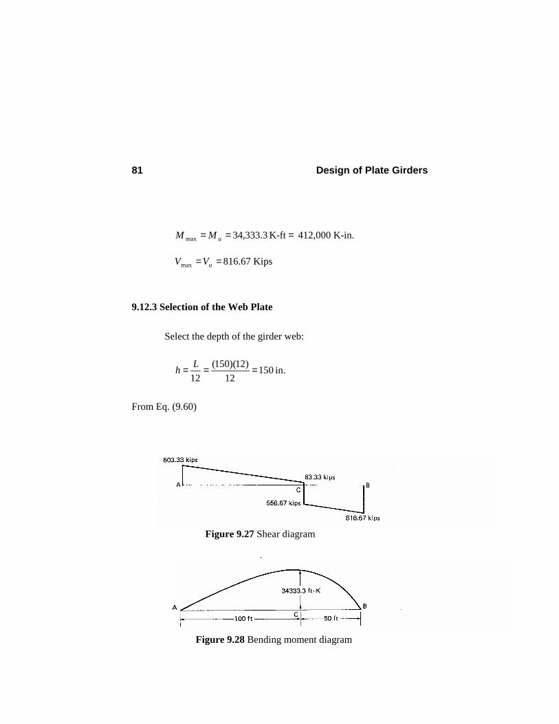
640)100(6.1)400(2.16.12.1 =+=+= LD PPP Kips 9.12.2 Shear and Bending Moment Diagrams Shear and bending moment diagrams for the factored loads are shown in Figs. 9.27 and 9.28, respectively. Maximum design bending moment and shear are
Design of Plate Girders 81
ft K 3.333,34max === -MM u 412,000 K-in.
67.816max == uVV Kips 9.12.3 Selection of the Web Plate Select the depth of the girder web:
15012
)12)(150(12
=== Lh in.
From Eq. (9.60)
Figure 9.27 Shear diagram
Figure 9.28 Bending moment diagram
Design of Plate Girders 82
322.0 for a > 1.5h
≤
wth
333.3 for a ≤ 1.5h
47.0322150
322==≥ htw in.
Try tw = 0.50 in. or PL150 in. x 0.5 in. for the web plate.
;300=wth 2in. 75=wA
9.12.4. Selection of the Flange Plates 1. Preliminary selection of the flange plates.
We find an approximate flange area from Eq. (9.79).
m = 1
3.72
12)75)(13(
)36)(150(9.0000,412 =−−=fA in.2
(9.95)
uL = unbraced length = 50ft = 600 in.
For the critical stress Fcr to be equal to the yield stress, from Eq. (9.81):
0.45)3.72/756)(36(2300
600 =+≥fb in. (9.96)
Design of Plate Girders 83
and from Eq. (9.82): 83.1)36()130/3.72( 4/12/1 =≥ft in. (9.97)
To begin with, based on Eq. (9.97), try tf = 2 in. Then, based on Eq. (9.95), try bf = 40 in.; Af = 80 in.2
838,064,1)175)(80(2)2)(40()150)(5.0( 23
1223
121 =+++=xI in.4
1.829,13
77838,064,1
77=== x
xI
S in.3
74.10
)]80/()75(212[40
)/212( 2/12/1 =+
=+
=fw
fT AA
br in.
For doubly symmetric girders, the nominal flexural strength on the basis of the limit state of tension-flange yield is always greater than or equal to the flexural strength on the basis of the limit state of compression-flange buckling. Therefore, only the latter needs to be checked.
2. Check for the limit state of compression-flange buckling:
a. Lateral torsional buckling
87.5574.10
600 ===T
u
rLλ
0.5036
300300 ===yf
pF
λ
Design of Plate Girders 84
From the LTB point of view, the middle segment of the girder (segment DC in Fig. 9.17) is the critical segment. The moment gradient coefficient Cb is found from Eq. (5.35).
MA = moment at quarter point of the unbraced segment = 9.551,27)5.62)(2.5()5.62(33.603 2
21 =− ft-K
MB = moment at center line of the unbraced segment
= 7.624,30)75)(2.5()75(33.603 221 =− ft-K
MC = moment at three-quarter point of the unbraced segment
= 1.885,32)5.87)(2.5()5.87(33.603 221 =− ft-K
10.1)1.885,32(3)7.624,30(4)9.551,27(3)3.333,34(5.2
)3.333,34(5.123435.2
5.12
max
max
=+++
=
+++=
CBAb MMMM
MC
0.12636
756756 ===yf
rF
λ
rp λλλ <<
ksi 36 ksi 07.3800.500.12600.5087.55
211)36)(10.1(
211
=>=
−−−=
−−
−=
yf
pr
pyfbcr
F
FCFλλλλ
Design of Plate Girders 85
∴ Fcr = 36 ksi.
b. Flange local buckling
10)2(2
402
===f
f
tb
λ
1083.1036
6565 =>=== λλyf
pF
36== yfcr FF ksi
Therefore, the governing critical stress is Fcr = 36 ksi.
912.036
970300)80/75(3001200
80/751
9703001200
1
=
−
+−=
−
+−=
crw
c
r
rPG
Fth
aa
R
in.K 633,408)00.36)(1.829,13)(912.0(9.0
-FSRM crxPGbnb
==φ=φ
The value of φb Mn is within 1% of Mu = 412,000 K-in. and PL40 in. x 2.0 in. is acceptable for the flange plate. If the section were not O.K., we would have to increase the area of the flange. We choose the second trial flange plate on the basis of the following estimate of the new required flange area:
Design of Plate Girders 86
New )/)( old( nbuff MMAA φ= (9.98)
We can use Eq. (9.98) also to possibly reduce the area of the flange when φb Mn is larger than Mu.
9.12.5 Intermediate Stiffeners 1. Check if intermediate stiffeners are required.
a. Check Eq. (9.89):
67.6936
418418300 ==>=yww Ft
h
b. Check Eq. (9.90) (with kv = 5):
2.87
365234234
300 ==>=yw
v
w F
kth
0679.0)36()300()5)(000,44(
)/(000,44
22 ===yww
vv Fth
kC
99)0679.0)(36)(75)(9.0(6.06.0 ==φ vywwv CFA Kips
This value is smaller than the maximum shear in segments AC and CB of the plate girder (Fig. 9.27). ∴ Intermediate transverse stiffeners are required.
2. Find the location of the first stiffener away from each end.
Design of Plate Girders 87
a. At the left end:
nnvu VVV 9.0 Kips 33.603 === φ Kips
From Eq. (9.88):
8.04138.0)]36)(75)(9.0(6.0/[33.603
]6.0/[
<==
φ= ywwvuv FAVC
From Eq. (9.87):
47.30000,44/)36)(4138.0()300(
000,44/)/(2
2
==
= ywvwv FCthk
From Eq. (9.84):
443.0)]47.25/(5[)]5/(5[/ 2/12/1 ==−= vkha
4.66)150(443.0443.0max === ha in.
Tentatively, place the first intermediate stiffener at a distance 45 in. from the left end A.
b. At the right end:
7.55max =a in.
Tentatively, place the first intermediate stiffener at a distance 50 in. from the right end B.
Design of Plate Girders 88
3. Find the spacing of the remaining stiffeners. As in the example of Sec. 9.8, we use uniform spacing between point E (at the location of the first intermediate stiffener from the left end) and point C (the location of the concentrated load) and also between point C and point F (at the location of the first intermediate stiffener from the right end), similar to Fig. 9.22. Whenever the aspect ratio a/h is greater than 3 or [260/(h/tw)]2, the coefficient kv shall be taken as 5. We limit the aspect ratio a/h to these values.
375.0
300260
/260 22
<=
=
≤
wthha
5.112)150(75.075.0max === ha in.
a. Spacing of the stiffeners between point E and C (Fig. 9.22):
Try a = 105 in.; a/h = 0.7. From Eq. (9.84):
20.15)7.0(
55)/(
55 22 =+=+=ha
kv
3001.15236
20.15234234=<==
wyw
v
th
F
k
From Eq. (9.87):
206.0
)36()300()20.15(000,44
)/(000,44
22 ===yww
vv Fth
kC
From Eq. (9.86):
Design of Plate Girders 89
Kips 1250)7.01(15.1
206.01206.0)36)(75(6.0
)/1(15.11
6.0
2/12
2/122
=
+−+=
+−
+=ha
CCFAV v
vywwn
1125)0.1250(9.0 ==nvVφ Kips
uvAu VwRV φ Kips 83.583)2.5(33.603 1245
1245 <=−=−= O.K.
b. Spacing of the stiffeners between C and F (Fig. 9.22).
Similar to case a, we find a = 110 in. to be satisfactory.
;194.0=vC 0.1230=nV Kips; 795=uV Kips
4. Check shear and bending interaction. We perform the interaction check at point C under concentrated load where the bending moment is the largest (actually, a very small distance to the right of point C).
000,412=uM K-in.; 67.556=uV Kips
487,465=nM K-in.; 1230=nV Kips
Since Vu is less than 0.6φVn = (0.6)(0.9)(1230) = 664.2 Kips, an interaction check is not necessary, Note that the spacing of the stiffeners in this example is the same as that for the example of Sec. 9.8 designed according to the ASD code and shown in Fig. 9.22.
Design of Plate Girders 90
5. Select intermediate stiffeners.
a. Region EC:
a = 105 in.; a/h = 0.7; vC = 0.206 From Eq. (9.91):
2
2
in. 14.0
3636)5.0(18
112583.583)206.01)(5.0)(150)(0.1(15.0
=
−−=stA
2in. 07.0=ss tb (9.99)
From Eq. (9.93):
5.010.32)7.0(5.22
)/(5.2
22 ≥=−=−=ha
j
From Eq. (9.92):
4
333121
in. 69.40
)10.3()5.0)(105()2(
=
=≥+= jattbtI wwssst
(9.100)
8.15
3695 =≤
s
s
tb
(9.101)
The area requirement of Eq. (9.99) is minimal. Therefore, bs and ts should be selected based on Eqs. (9.100) and (9.101). The
Design of Plate Girders 91
minimum thickness to satisfy Eqs. (9.100) and (9.101) is ts = 3/8 in. From Eq. (9.101):
92.5≤sb in.
Try 2PL5.5 in. x 3/8 in. From Eq. (9.100):
443
121 in. 69.40in. 53.47)5.011)(375.0( ≥=+=stI O.K.
Use 2PL5.5 in. x 3/8 in. for intermediate stiffeners from E to C.
b. Region CF:
a = 110 in.; a/h = 0.733 The answer is the same as for region EC.
Use 2PL5.5 in. x 3/8 in. for intermediate stiffeners from C to F. 9.12.6 Bearing Stiffeners Design of bearing stiffeners according to LRFD K1.9 is similar to the design according to the ASD code covered in section 9.6. Noting that the width of the flange plate is 40 in. and the thickness of the web is 0.5 in., we choose a width of bbs = 19 in. for all bearing stiffeners. 1. Bearing stiffeners at supports.
We design the support bearing stiffeners based on the larger shear at support B, RB = 816.67 Kips. To satisfy the buckling requirement we must have
Design of Plate Girders 92
20.1)19(
9536
95==≥ bs
ybs b
Ft in.
Try 2PL19 in. x 1¼ in.; Abs = 23.75 in.2 The effective area for finding the axial compressive load capacity is found from Eq. (9.31)
222 in. 50.50)5.0(12)75.23(2122 =+=+= wbseff tAA
4345
121 in. 5944.40.5)19)(19( =++=I
in. 10.8550.504.5944 === /I/Ar eff
37.1085.10
)150)(75.0( ==r
KL
5.1116.0000,293637.10
2/1
2
2/1
2 <=
=
=
ππλ
EF
rKL y
c LRFD E2
ksi 80.35
)36)(658.0()658.0(22 116.0
=
== ycr FF cλ
9.1807)80.35)(50.50( === creffn FAP Kips
17.816 Kips 7.1536)9.1807(85.0 =>== Bnc RPφ Kips O.K.
Use 2PL19 in. x 1¼ in. x 12 ft 6 in. for the bearing stiffeners at the left and right supports.
2. Bearing stiffeners at concentrated load.
Design of Plate Girders 93
Buckling requirement governs. Therefore, Use 2PL19 in. x 1¼ in. x 12 ft 6 in. at the location of concentrated
load.
9.12.7 Girder Weight γ = specific gravity of steel = 0.490 Kips/ft3 Weight of the flange plates = 2Af Lγ = 2( 144
80 )(150)(0.49) = 81.7 Kips Weight of the web plate = Aw Lγ = 2( 144
75 )(150)(0.49) = 38.3 Kips
Weight of the flange and web plates = 81.7 + 38.3 = 120.0 Kips Weight of the stiffeners = [(3)(2)(19)( 4
5 )(150) + (16)(2)(5.5)( 83 )(148)](0.49/123)
= 8.8 Kips Total weight of the plate girder = 120.0 + 8.8 = 128.8 Kips Comparing the weight of this design based on the LRFD code with the corresponding one based on the ASD code presented in section 9.8, we observe that the former is about 11 percent lighter than the latter. 9.13 WEB-BASED INTERACTIVE DESIGN OF PLATE GIRDERS
The applet presented in this section is for interactive design of homogeneous and hybrid plate girders according to the ASD and LRFD codes. This applet consists of three windows: input window, output window and control window (Fig. 9.29).
Design of Plate Girders 94
The input window consists of Configuration panel, Flange & Web panel, Stiffeners panel, and Welds Panel. The user can enter the corresponding input for the design of plate girders in those panels.
Span length, lateral supports (similar to applet for design of beams described in Sec. 5.11), and distributed and concentrated loads are set in the configuration panel (Fig. 9.29). The loading on the girder may consist of a uniformly distributed load plus a specified number of concentrated loads. The concentrated loads are named alphabetically from left. Alphabets “A” and “B” are reserved for the left and right supports, respectively. The girder may have either full lateral support or intermediate lateral supports.
Width, thickness, and steel type of flange plates and thickness and steel type of the web plate are set in the flange & web panel (9.30a). To begin the design of a plate girder the user needs to specify the steel types of flange and web plates only. The applet displays the first design results as shown in Fig. 9.30b. Like other applets presented in the previous chapters, this applet requires minimum amount of design entry to perform a design. However, the user can perform redesigns repeatedly simply by changing only one or several of the input values.
To design a hybrid girder, the user needs to select the steel types of flange plates and web plate properly. For impractical values, for example, if the user selects a steel type for flange plates with lower strength than that of the web, the applet warns the user with a pop-up message shown in Fig. 9.31.
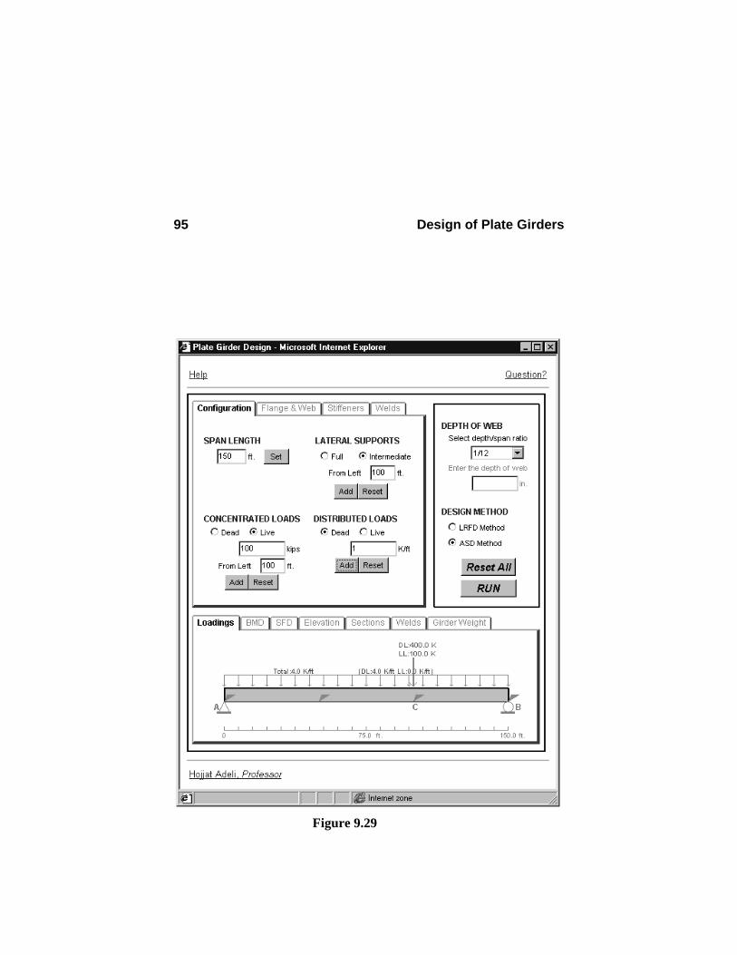
Design of Plate Girders 95
Figure 9.29
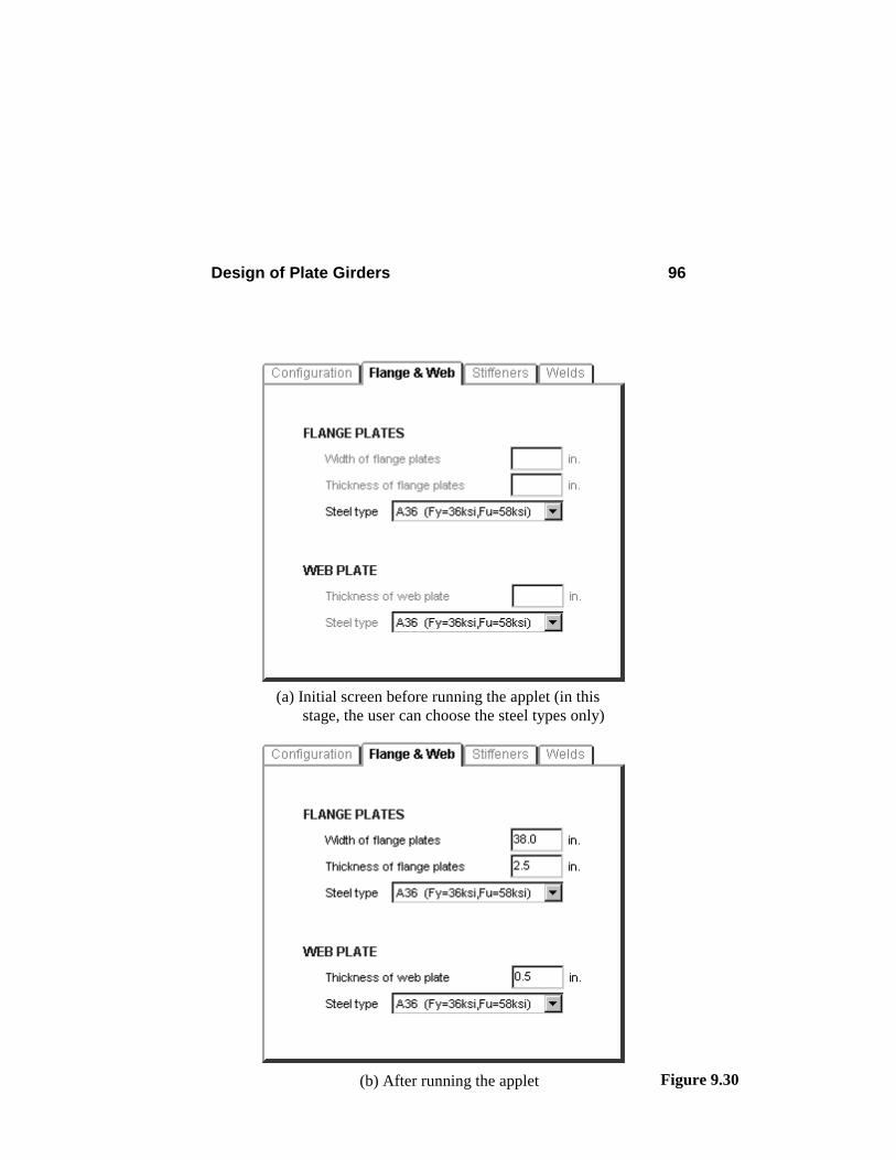
Design of Plate Girders 96
Figure 9.30
(a) Initial screen before running the applet (in this stage, the user can choose the steel types only)
(b) After running the applet
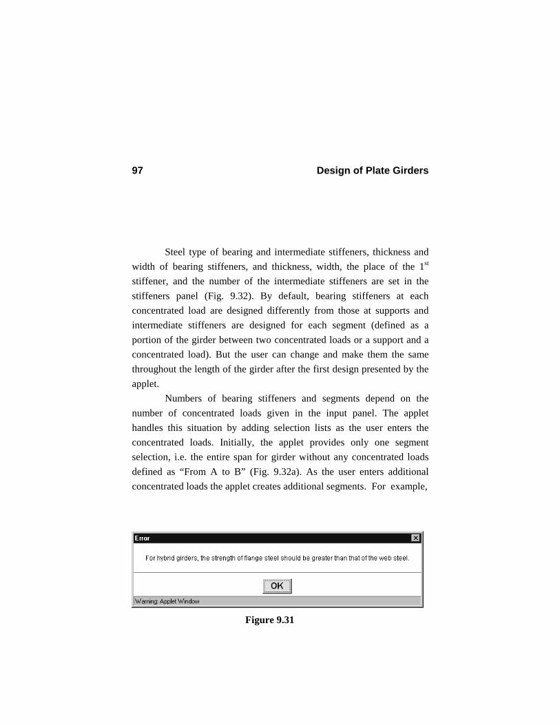
Design of Plate Girders 97
Steel type of bearing and intermediate stiffeners, thickness and
width of bearing stiffeners, and thickness, width, the place of the 1st stiffener, and the number of the intermediate stiffeners are set in the stiffeners panel (Fig. 9.32). By default, bearing stiffeners at each concentrated load are designed differently from those at supports and intermediate stiffeners are designed for each segment (defined as a portion of the girder between two concentrated loads or a support and a concentrated load). But the user can change and make them the same throughout the length of the girder after the first design presented by the applet.
Numbers of bearing stiffeners and segments depend on the number of concentrated loads given in the input panel. The applet handles this situation by adding selection lists as the user enters the concentrated loads. Initially, the applet provides only one segment selection, i.e. the entire span for girder without any concentrated loads defined as “From A to B” (Fig. 9.32a). As the user enters additional concentrated loads the applet creates additional segments. For example,
Figure 9.31
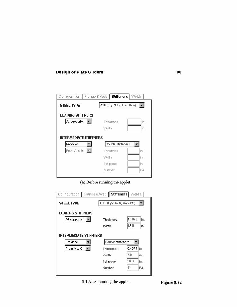
Design of Plate Girders 98
Figure 9.32 (b) After running the applet
(a) Before running the applet
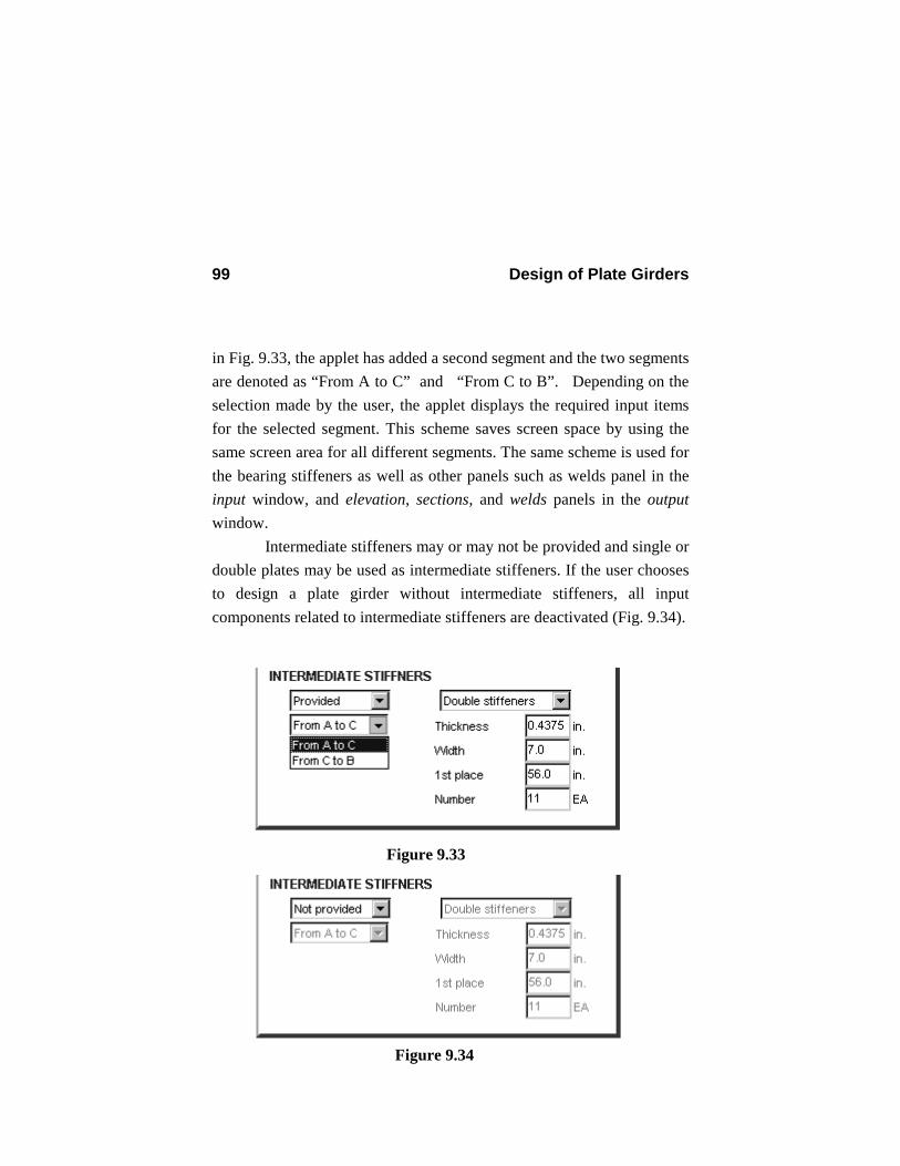
Design of Plate Girders 99
in Fig. 9.33, the applet has added a second segment and the two segments are denoted as “From A to C” and “From C to B”. Depending on the selection made by the user, the applet displays the required input items for the selected segment. This scheme saves screen space by using the same screen area for all different segments. The same scheme is used for the bearing stiffeners as well as other panels such as welds panel in the input window, and elevation, sections, and welds panels in the output window.
Intermediate stiffeners may or may not be provided and single or double plates may be used as intermediate stiffeners. If the user chooses to design a plate girder without intermediate stiffeners, all input components related to intermediate stiffeners are deactivated (Fig. 9.34).
Figure 9.33
Figure 9.34
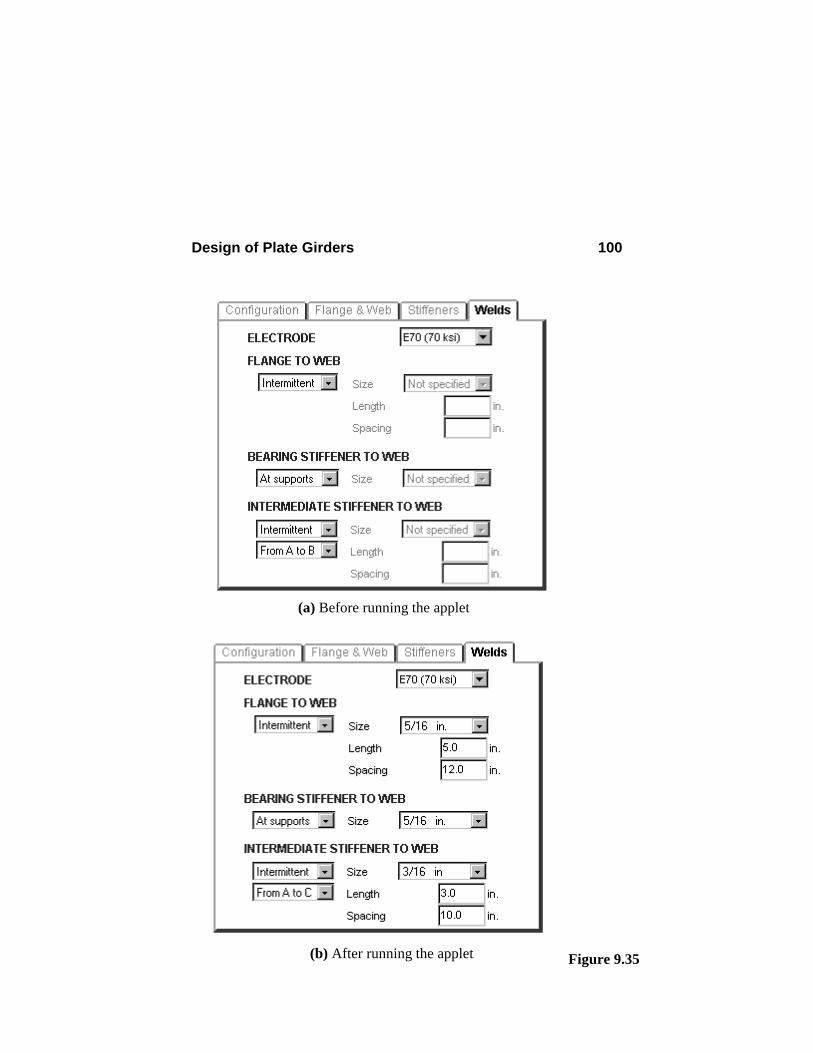
Design of Plate Girders 100
Figure 9.35
(a) Before running the applet
(b) After running the applet
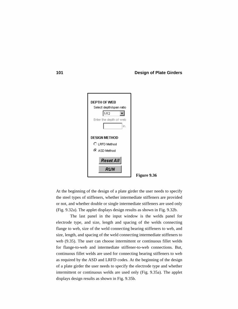
Design of Plate Girders 101
At the beginning of the design of a plate girder the user needs to specify the steel types of stiffeners, whether intermediate stiffeners are provided or not, and whether double or single intermediate stiffeners are used only (Fig. 9.32a). The applet displays design results as shown in Fig. 9.32b.
The last panel in the input window is the welds panel for electrode type, and size, length and spacing of the welds connecting flange to web, size of the weld connecting bearing stiffeners to web, and size, length, and spacing of the weld connecting intermediate stiffeners to web (9.35). The user can choose intermittent or continuous fillet welds for flange-to-web and intermediate stiffener-to-web connections. But, continuous fillet welds are used for connecting bearing stiffeners to web as required by the ASD and LRFD codes. At the beginning of the design of a plate girder the user needs to specify the electrode type and whether intermittent or continuous welds are used only (Fig. 9.35a). The applet displays design results as shown in Fig. 9.35b.
Figure 9.36
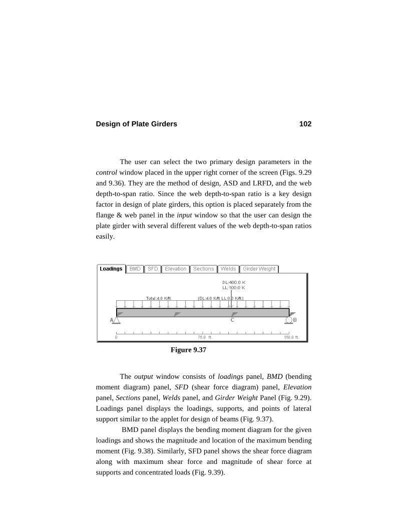
Design of Plate Girders 102
The user can select the two primary design parameters in the control window placed in the upper right corner of the screen (Figs. 9.29 and 9.36). They are the method of design, ASD and LRFD, and the web depth-to-span ratio. Since the web depth-to-span ratio is a key design factor in design of plate girders, this option is placed separately from the flange & web panel in the input window so that the user can design the plate girder with several different values of the web depth-to-span ratios easily.
The output window consists of loadings panel, BMD (bending moment diagram) panel, SFD (shear force diagram) panel, Elevation panel, Sections panel, Welds panel, and Girder Weight Panel (Fig. 9.29). Loadings panel displays the loadings, supports, and points of lateral support similar to the applet for design of beams (Fig. 9.37).
BMD panel displays the bending moment diagram for the given loadings and shows the magnitude and location of the maximum bending moment (Fig. 9.38). Similarly, SFD panel shows the shear force diagram along with maximum shear force and magnitude of shear force at supports and concentrated loads (Fig. 9.39).
Figure 9.37
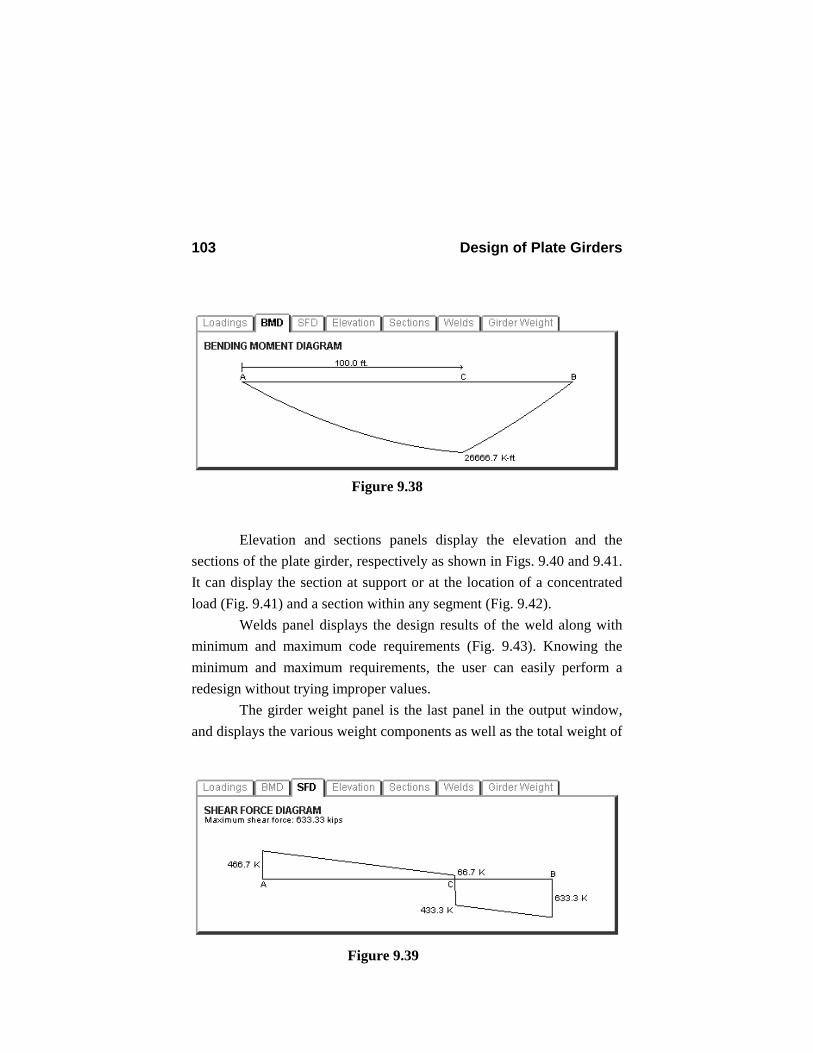
Design of Plate Girders 103
Elevation and sections panels display the elevation and the sections of the plate girder, respectively as shown in Figs. 9.40 and 9.41. It can display the section at support or at the location of a concentrated load (Fig. 9.41) and a section within any segment (Fig. 9.42).
Welds panel displays the design results of the weld along with minimum and maximum code requirements (Fig. 9.43). Knowing the minimum and maximum requirements, the user can easily perform a redesign without trying improper values.
The girder weight panel is the last panel in the output window, and displays the various weight components as well as the total weight of
Figure 9.39
Figure 9.38
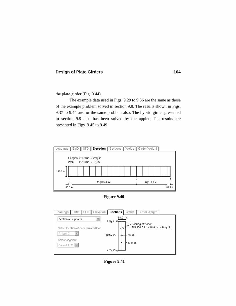
Design of Plate Girders 104
the plate girder (Fig. 9.44). The example data used in Figs. 9.29 to 9.36 are the same as those
of the example problem solved in section 9.8. The results shown in Figs. 9.37 to 9.44 are for the same problem also. The hybrid girder presented in section 9.9 also has been solved by the applet. The results are presented in Figs. 9.45 to 9.49.
Figure 9.41
Figure 9.40
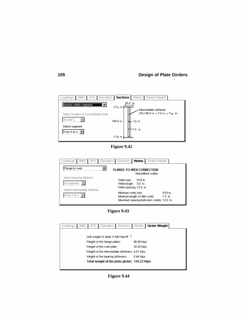
Design of Plate Girders 105
Figure 9.42
Figure 9.43
Figure 9.44

Design of Plate Girders 106
Figure 9.45
Figure 9.46
Figure 9.47
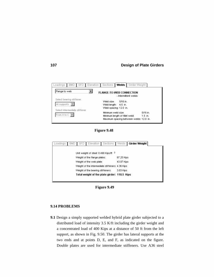
Design of Plate Girders 107
9.14 PROBLEMS 9.1 Design a simply supported welded hybrid plate girder subjected to a
distributed load of intensity 3.5 K/ft including the girder weight and a concentrated load of 400 Kips at a distance of 50 ft from the left support, as shown in Fig. 9.50. The girder has lateral supports at the two ends and at points D, E, and F, as indicated on the figure. Double plates are used for intermediate stiffeners. Use A36 steel
Figure 9.48
Figure 9.49
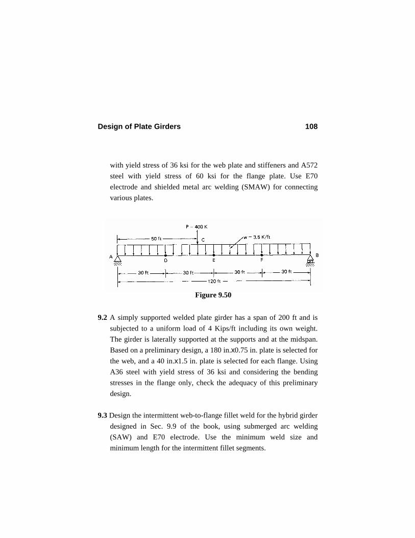
Design of Plate Girders 108
with yield stress of 36 ksi for the web plate and stiffeners and A572 steel with yield stress of 60 ksi for the flange plate. Use E70 electrode and shielded metal arc welding (SMAW) for connecting various plates.
9.2 A simply supported welded plate girder has a span of 200 ft and is
subjected to a uniform load of 4 Kips/ft including its own weight. The girder is laterally supported at the supports and at the midspan. Based on a preliminary design, a 180 in.x0.75 in. plate is selected for the web, and a 40 in.x1.5 in. plate is selected for each flange. Using A36 steel with yield stress of 36 ksi and considering the bending stresses in the flange only, check the adequacy of this preliminary design.
9.3 Design the intermittent web-to-flange fillet weld for the hybrid girder
designed in Sec. 9.9 of the book, using submerged arc welding (SAW) and E70 electrode. Use the minimum weld size and minimum length for the intermittent fillet segments.
Figure 9.50
Design of Plate Girders 109
9.4 Solve Example 1 of section 9.10, assuming that the plate girder consists of two WT12x52 with yield stress of 60 ksi and a 100 in. x 0.50 in. plate with yield stress of 36 ksi.
9.5 Design the bearing stiffeners in Example 1 of Sec. 9.10. 9.6 Design the intermediate stiffeners in Example 1 of Sec. 9.10, using
a. single stiffeners b. double stiffeners