design recommendations for plate girdersdigital.lib.lehigh.edu/fritz/pdf/251_22.pdfdesign...
TRANSCRIPT

DESIGN RECOMMENDATIONSFOR PLATE GIRDERS
Lehigh UniversityFritz Engineering Laboratory
Rep. 251.22March, 1961

'.
ii
FOREWORD
The numerical values are worked out for girders made
of A7 steel (Fy = 33 ksi) with assumed values of
E = 30,000)000 psi and v = 0030 They are supposed to
apply to the AISC Specification. The values added in
parenthesis apply to the AASHO Specification.
The nomenclature used here conforms to AISC
practice. For convenience the standard symbols as
applied in all the Lehigh plate girder publications
are added to the right of the list.

".
iii
NOMENCLATURE
AISCLehigh
Plate GirderLiterature
Af Area of compression flange Af
As Area of transverse stiffener As
Aw Area of web Aw
a Panel length~ measur'ed from centerline to acenterline of transverse stiffener
b Width of comp!'19 "Hidon flan ge 2c
h Web d19pth~ measured from border to border bof the web plate.
Cl stress modification coerficient~ depending on 01moment gradient
c Distanoe between flange centroid and neutral Yoaxis,
e Distance between the centerline of the end ebearing stiffener to the girder end.
I Moment of Inertia I
Is Moment of inertia of transverse stiffeners Is
e Effective lateral buckling length e
M Bending moment M
I' Radius of gyration I'
s Smaller of the two panel dimensions s
Vi Shear flow between web and transverse stiffener Vi
t Flange thicknesS$ Web thickness d,t
fb Bending stress
v Shearing stress
cr
=1
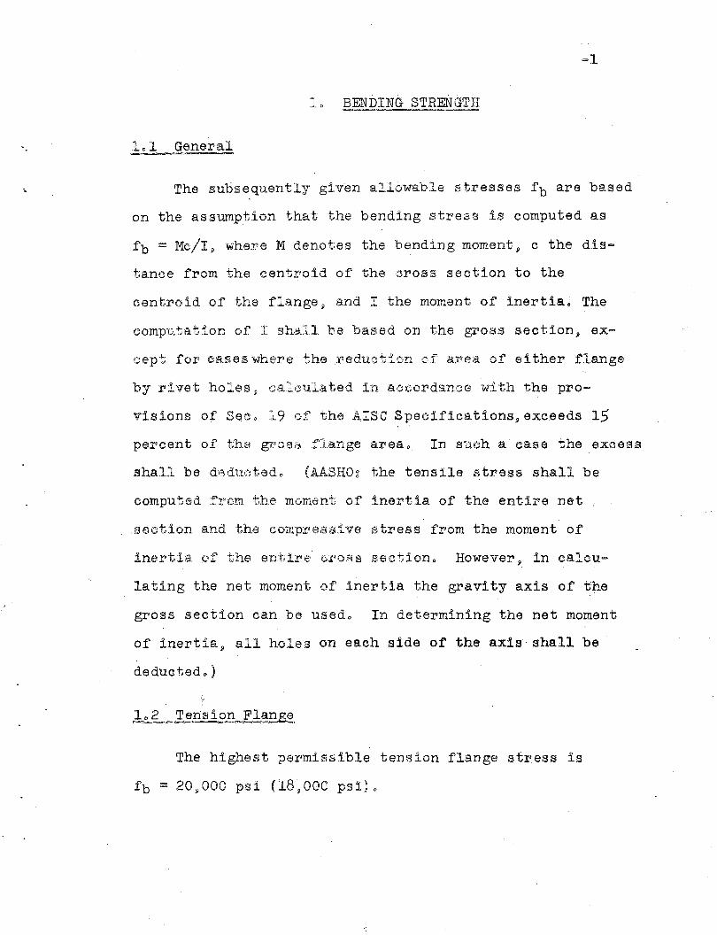
10 BENDING ST,flENGTH
101 General~
The subsequently given allowable stresses f b are based
on the assumption that the bending stress is computed as
fb = Mc/I~ where M denotes the bending moment~ c the dis~
tance from the centroid of the cross section to the
centroid of the flange~ and I the moment of inertiao The
computation of I she.l1 be based on the gross section» ex~
cept for {~afleS where thsreducti'on 0.1"' ax'sa of eIther flange
by rivet holes, calculated in aocordance with the pro=
visions of Seco 19 of the AlSa Speoifications,exceeds 15
percent of the gross flange area o In such a case the excess
shall be d(2duc;tedo (AASHO~ the tensile stress shall be
computed from the moment of inertia of the entire net
section and the compressive stress from the moment of
inertia. of the enti:r'8 cro,'5 s sectiono However'» in calcu=
lating the net moment of inertia the gravity axis of· the
gr'oss section can be usedo In determining the net moment
of inertia» all holes on each side of' the axis shall be
deductedo)
].02 Tension Flange
The highest permissible tension flange stress is
fb = 20~000 psi (18»000 psi)o

"
=2
"
the most highly stressed section is given by
f b = 20~OOO 0ct£ <;>2
( fb :=; 18 000 = 9 0 5Q. (1)2) in whichII C' I'
1
( is the lateral buckling length ll which is in-generalthe distance between latera.1 bracing points o' - If atpoints of lateral br~H:dng the ;,,;;'orrrp:t'essi6n -flange -isnot rigidly held again6t late~al displacements ll suchas the case in a through type girder bridge,thee:ffective lateral buckling length C:b:.n be computedas t;::; 205 ~.J Eli"g'll in whi<6:h EI is the I,ataral rigidityof the compI'es sion flange in k = in2 Sl .f is the distance'between adjaoent frames yielding ela~tio later&l ... supports {measured in inches~ and g (measured in inches)is the virtual lateral displacement of eithe~ le~br the bri5.o1ng .i':,i;ame at.flange elevation ll - due to a unitload of 1 kip &!.eting at the location and in the di1"ee=tion of the di81plaeement 0 In no Icase can t be takenless thsm f c
r
For plate girders ll whose compression flange has the shape
of a rectangle ll r can be expressed in terms of the flange width
b II in which case an alternate fOI'm of the lateral buckling
equation iag
"
"
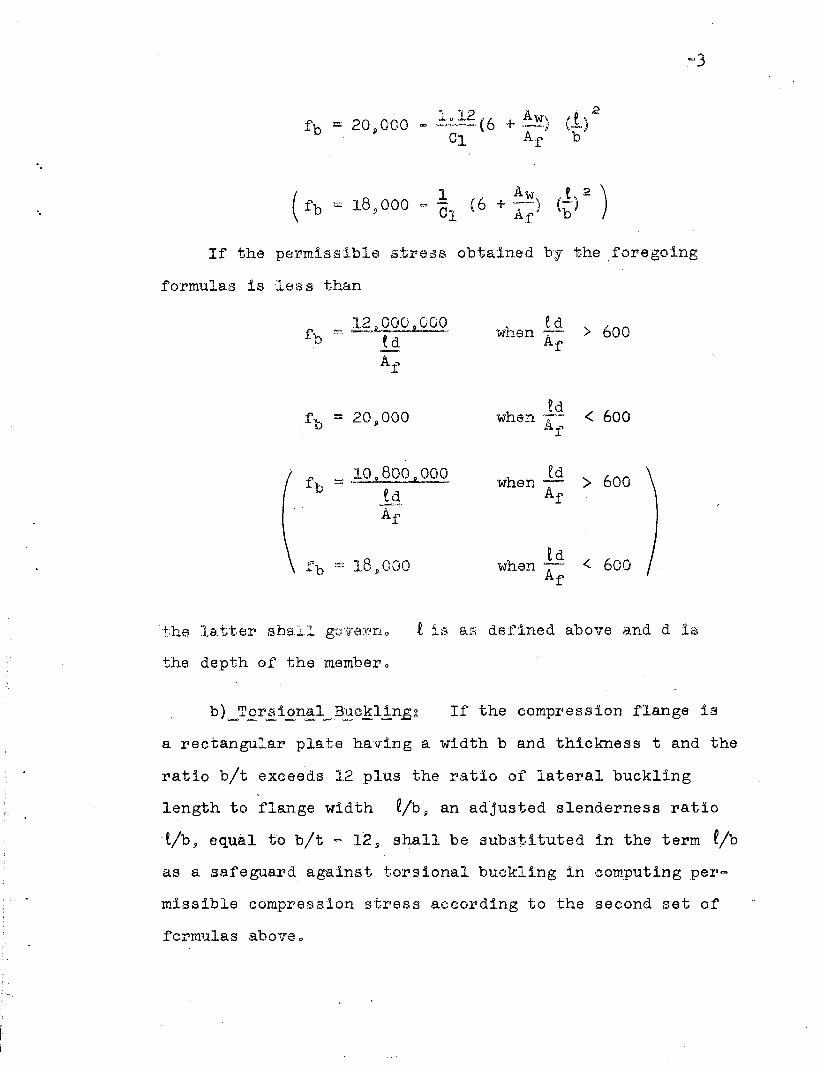
If the permissible stress obtained by the foregoing
formulas is less than
12 000 000f _._._.. 2..~_b ~ ~d
A.f
fb :=; )~2~~Q.OOedAf
~e d > 600W~1en ~A
f
~dwhen ~~. < 600Af
edwhen A > 600
f
£dwhen A .. <. 600
f
the latter shall gc.nl'e:ii:"no t 18 e.g defined above a.nd d L~
the depth of the membero
If the compression flange is
a rectangular pla.te having a width b and thickness t and the
ratio bit exceeds 12 plUS the ratio of lateral buckling
length to flange width e/b9 an adjusted slenderness ratio
.lib, equal to bit "" 12, shall be subl3tituted in the term fib
as a safeguard against torsional buckling in computing per'-
missible compression stress according to the second set of
formulas a.bov6o

(po = 170 i 18~:oo '1
c}_Verli£al Bue~!ing~ In order to prevent the com~
pression flange from buekling into the web J the web depth=
to~thickness ratio must not exceed 360 (340) and transverse
loads should be introduced through stiffeners.
d)_Web="parti0il2.ati.£n~ In slender~web girders the par=
ticipation of the compression portion of the web in carrying
the bending moment :is less than assu.med by ordinary beam
theory. An increase of the compression flange stress beyond
the value computed from Mo/r will CO'\ler this deficiency. To
allow for this increase the permissible flange stress J com
puted as equai to Mc/I~ must be reduced by an amount depen~
dent upon the web dep'th·,thicknesB l"atio (3 :::; hit and the
ratio of web area to compression flange area Aw/Af.
Up to a web depth=to=thickness ratio
(30 ::=; 170 201~~oq
the permissible bending stress fb as de~ermined by the para
graphs (a) and (b) requires no reduction. lfthe web slender
ness ratio exceeds this limit in the amount of A(3 = h - (30't
the reduction of the bending stress f b in percent is
Aw0.05-- . A(3, Af
"
"
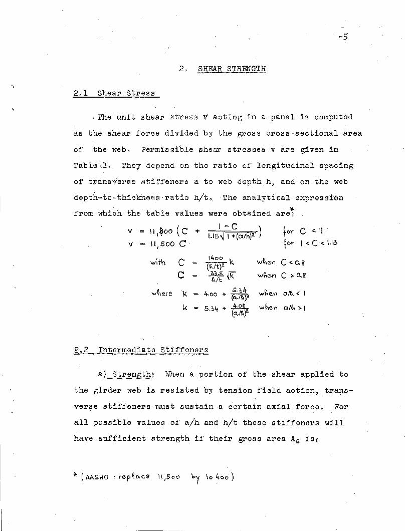
20 ,§,HEAR STRENGTH
2~1 Shear,Stress
, The unit shear stress 'It acting in a panel is computed
as the shear force divided by the gxaoss CI'oss=sectional area
of the webo Permissible shear stresses v are given in
Table1l._ They depend on the ratio of longitudinal spacing
of trans1ierse stiffeners a to web depth h~ and on the web
depth~to=thickness: I'a tio hit 0 The B.rJalytical expres slon
*-from which the table values were obtained are~
v ( I-C)"" 11,$00 C + 1.15~ I +(~/h):2.'
V = 11,500 Ctor C <. '1
for '< C<. I.I~
w;th C1400
w~el1 C <. O.g= '(~/t)Z kC = '~{k 'W'~e.V1 C > O,R
~/t
w~ere 'l( 4.00 + .5·~4 w~eVl ale.. < I(ClJ~)1
k = 5.~4- +~ w~eY) a/t.. ~ I(o../e..)'I..
2.2 Intermediate Stiffeners
a)_Slr~n.Bth~ When a portion of the shear applied to
the girder web is resisted by tension field action» trans
ver~e stiffeners must sustain a certain axial force. For
all possible values of alh and hit these stiffeners will
have sufficient strength if their gross area,As is~
*' (AASHO : rep ~o.ce -1\ ,S 00 by \0 400 )
"
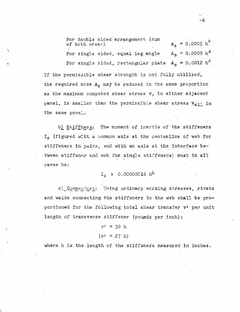
For double sided arrangement (sumh
2of both arel:u:'ii) As ::::: 0.0005
For single sided~ equal leg angle As :=:: 0.0009 h 2
For single sidedj) rectangular plate A· = 0.0012 h2:s
If the permissible shear strength is not fully utilized,
the required area As may be reduced in the same proportion
as the maximum computed shear stress v, in either adjacent
panel, is smaller than the permissible shear stress Vall in
the same p8.ne 1. 0
bl Stiffnes~g The moment of inertia of the stiffeners
.Is (figured with a common axis at the centerline of web for
stiffeners in pa.iri5j) and with an a.xis at the interface be=
tween stiffener and web for single ~tlffeners) must in allL
cases be~
and welds connecting the stiffeners to the web shall be pro=
portioned for the following total shear transfer v' per unit
length of'transverse stiffener (poUnds per inch)~
yV = 30 1;1
(V V :: 27 h)
where h Is the length of the stiffeners measured in inches.

-7
Transverse stif'feners may be stopped
" short at the tension flange. The clearance}) however}) should" ,
not exceed 4 times the web thickness (3 ~ times the' web
thickness) 0 The stiffeners must stay the compression flange.
In case of stiffeners in pairs simple bearing is sUfficient;
if single stiffeners are placed at one side only, provisions
against the uplift tendency due to torsion in the flange-
plate must be m,9.de o
If latl;lI"al bracingi8 attached to thesti.ffener}) a shear
connection between the end of the stiffener and the compression
flange should be provided. this should oe strong enough to
transfer one percent of the ~aximum total compression flange
force. Such connections for shear transfer is not needed
when the flange is composed of angles.
2 0 3Ehd Stiffeners
Provision must be made ~tthe ends of girders,'des1gned
on the basis of tension f1el9, action,,}) to resist the hori
zontal component of the tension field stresses with a rigid;,
means of support. This can be accomplished by limiting the
smaller of the two dimensions s of the end panels to not
more than "
s = l~,OOO t/{V'
(8 = 9000 t/ {V)

"
u
-8
where the shearing stress v in the end panel is -expressed
in poUnds per square inches and sand t in inches. When
so proportioned the web in the end panel can support· the
shear by ordinary beam action without the assistance of a
- tenslon field 0
The bearing stiffeners over the supports of unframed
stiffeners C&L'lJ. be reinforced to function as beams spanrting
between the top and bottom flange to resist the horizontal
component of a tenfSion field .in the end panelo Extending
the web a distance e beyond the centerline of the bearing
stiffener and adding a vertical flange plate to' produce -an
H-type profile of approximate depth e~ the required area
of this flange plate can be computed as
with V expressed in pOln1ds a~d the linear dimensions e~ 1'1,
s, and t ih inChes.
AASHO~ A

-9
30 INTERACTION
3.1 General
The pending stress f b and the shear stress v must not
exceed the permissible value~ specified in Part 1 and Part 2~
respectivelyo In Ga~e the shear stress exceeds 60% of the
allowable shear stress va ll·and 9 simultaneously, the bending
stress in the highest 8tressed cross section of a given panel
is beyond 15~OOO Ibs/in29 (13,500 Ibs/in2 ) an interaction
check is indicated, where the permissible coexistent stresses
are determined by the following inequality~
f b <. 27,000 Co 12 000 .:!--, . Vall
vCfb <. 24,500 = 11,-000 --)Vall'
;3 02 Continuous Girder's
. Over an interior support of a continuous girder the
above given interaction condition must apply to the com
pression flange stress only and not to the stress in the
tension flangeo

· .""'" ... ..-
TABLE IPERMISSIDLE SHEAR STRESSES IN PLATE qIRDERS
(in kips per square inch)
Aspect ratios a/h~ stiffener spacing to web depth
0.5 0-06 0.7 0 08 0 09 1.0 1.2 1.4 1.6 1.8 200' 205 300 Over3~0
Under 70 13.0 13.0 13.0 13 0 0 13.0 1300 13 00 13 00 1300 13 0 0 1300 13.0 1300 1300
70' 13.0 13.0. 13.0 1300 13 00 13.0 13 00 13.0 1300 1300 1300' 1300' 13 00 130080 13.0 13 00 13.0 13 00 13 0 0 1300 1300 1300 1205 12 02 1200 11.7 ~L5 lLc.L.90 1300 13 00 1300 13 00 13 00 1300 12 02 11.6 11.3 11.2 11.1 1008 10 07 10 00
100 1300 13 0 0 1300 1300 12 06 11.8 11 03 11 01 10 08 1006 10.4 1001 909 806I1l 110 13.0 13 00 1300 12 06 11 04 1103 10 08 10 05 10 01 9 08 906 901 808 7 01
o. I1l . 120 ... 130 0 '13~'0 . 120411 0411;2 '10 08 10 03 9.8 904 9 00 808 8.2 709 6 00+!O,)
~ 130 13.0 1300 1105 11 02 10 09 1005 908 9.4 808 805 802 706 7 01 501(,)
140 13;012 02 11.3 11 00 10 06 1000 903 809 803 800 706 700 6 06 404l1lor-t0.0 150 1300 11 05 ~Loo. 10 07 1002 906 809 805 800 706 702 606 6 01 309oM~
+! 160 12.1 11 03 1008 10 04 909 903 8 06 801 706 7.2 609 603 5~8 304m,bHO,)
170 1105 11 01 1006 10 01 906 900 804 709 703 6 09 606 509 504 300~111 0 180 11 04 10 08 1003 909 .904 809 8 01 707 700 607 604 507 5~211l+!0,)
200 11 01 10 05 9.9 905 805 708 7 ..3 607 6 03 600 502 408P.o 900H+!
10 08 9.6 807 803 7.6 604 6 00 5070,) p, 220 10 02 9 02 7.0'"00,)4P'd 2 0 10 06 10 00 90·4 9 00 8.5 8.0 7.4 608 6.20,)MoD 260 10.3 9.8 9.2 .808 804 709f/) ~ 280 10.1 9 06 9 00 807 8.2
300 10.0 9.5 8.9 8.5 8 0 1320 908 9.3 8.8 8.4 Intermediate340 907 9.2 8.7 8.3 st iffeners.360 9.6 9.1 8.6 not required