82215765 autodyn basics
DESCRIPTION
basicsTRANSCRIPT

3-1ANSYS, Inc. Proprietary© 2009 ANSYS, Inc. All rights reserved.
February 27, 2009Inventory #002665
Chapter 3
AUTODYN Basics
ANSYS AUTODYN

AUTODYN Basics
3-2ANSYS, Inc. Proprietary© 2009 ANSYS, Inc. All rights reserved.
February 27, 2009Inventory #002665
Training ManualStructured and Unstructured Parts (Meshes)• An AUTODYN Part can use a
Structured mesh or an Unstructuredmesh
– Structured meshes can be generated in AUTODYN
• Use (I,J,K) index space
– Unstructured meshes must be imported (e.g. from Workbench)
• Lagrange Parts (Solid, Shell, Beam)
– Can be Structured or Unstructured
– Unstructured Parts are solved more efficiently (speed and memory)
• A Structured Part can be converted to an Unstructured Part prior to solving
– Lagrange Parts (structured or unstructured) can be used to “fill” regions of Euler and SPH Parts
• Euler and ALE Parts
– Always Structured
– Euler meshes are usually rectilinear

AUTODYN Basics
3-3ANSYS, Inc. Proprietary© 2009 ANSYS, Inc. All rights reserved.
February 27, 2009Inventory #002665
Training Manual
i
j i = 1 i = 11
j = 1
j = 6
Structured Parts - Index Space
• Each Structured Part in AUTODYN has a defined index space (i,j) in 2D or (i,j,k) in 3D, where i, j and k are integer values ranging from 1 to Ni, Nj, Nk
– This index space is always rectangular

AUTODYN Basics
3-4ANSYS, Inc. Proprietary© 2009 ANSYS, Inc. All rights reserved.
February 27, 2009Inventory #002665
Training Manual
x
yi = 1 i = 11
j = 1
j = 6
Structured Parts - Physical Space
• Each Structured Part is also defined in a physical xyz-space, where x, y and z are real values
– The mesh can have a general shape in physical space

AUTODYN Basics
3-5ANSYS, Inc. Proprietary© 2009 ANSYS, Inc. All rights reserved.
February 27, 2009Inventory #002665
Training Manual
Index Space Physical Space
Unused
Elements
• Not all elements defined in the index space need to be defined in physical space
– Elements not assigned a material are Unused
– Allows complicated geometries to be meshed
Structured Parts – Unused Elements
AUTODYN Basics
3-6ANSYS, Inc. Proprietary© 2009 ANSYS, Inc. All rights reserved.
February 27, 2009Inventory #002665
Training Manual
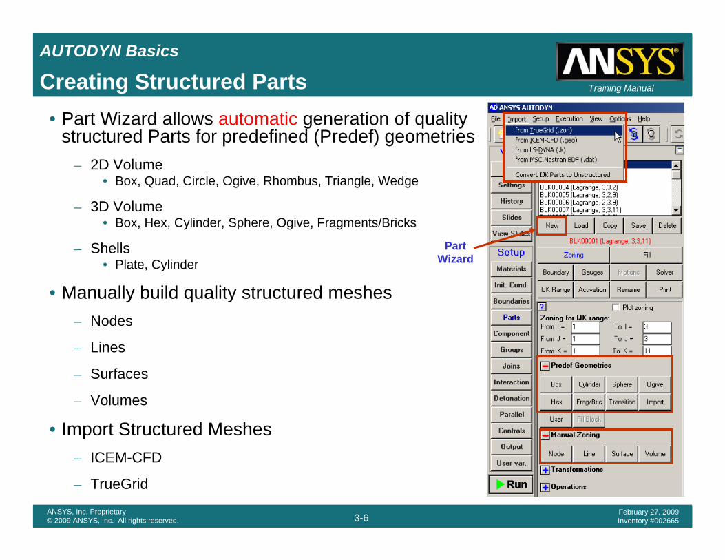
• Part Wizard allows automatic generation of quality structured Parts for predefined (Predef) geometries
– 2D Volume • Box, Quad, Circle, Ogive, Rhombus, Triangle, Wedge
– 3D Volume • Box, Hex, Cylinder, Sphere, Ogive, Fragments/Bricks
– Shells• Plate, Cylinder
• Manually build quality structured meshes – Nodes
– Lines
– Surfaces
– Volumes
• Import Structured Meshes– ICEM-CFD
– TrueGrid
Part Wizard
Creating Structured Parts

AUTODYN Basics
3-7ANSYS, Inc. Proprietary© 2009 ANSYS, Inc. All rights reserved.
February 27, 2009Inventory #002665
Training ManualPart Wizard
Geometry Zoning Fill
• Part Wizard generates a Part in three steps
– Define a Predef geometry
– Define the zoning
– Fill the whole Part

AUTODYN Basics
3-8ANSYS, Inc. Proprietary© 2009 ANSYS, Inc. All rights reserved.
February 27, 2009Inventory #002665
Training ManualPart Wizard – 2D Box Predef

AUTODYN Basics
3-9ANSYS, Inc. Proprietary© 2009 ANSYS, Inc. All rights reserved.
February 27, 2009Inventory #002665
Training ManualPart Wizard – 2D Circle Predef
AUTODYN Basics
3-10ANSYS, Inc. Proprietary© 2009 ANSYS, Inc. All rights reserved.
February 27, 2009Inventory #002665
Training Manual
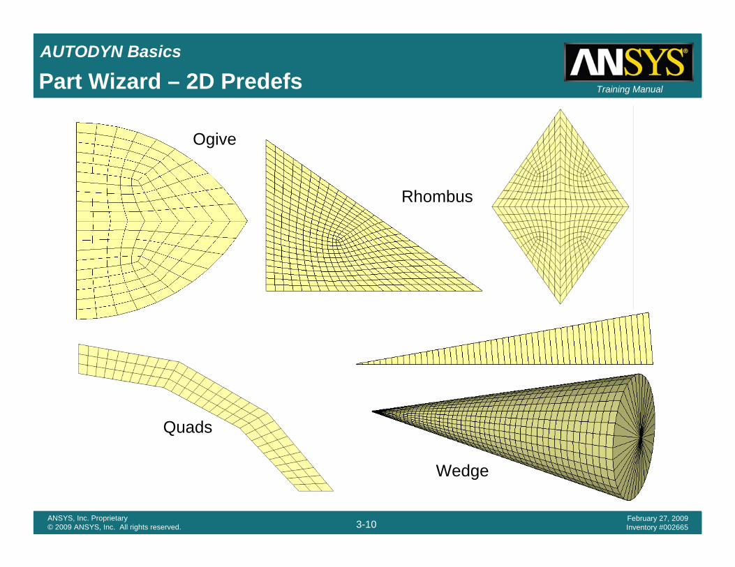
Ogive
Quads
Part Wizard – 2D Predefs
Wedge
Rhombus

AUTODYN Basics
3-11ANSYS, Inc. Proprietary© 2009 ANSYS, Inc. All rights reserved.
February 27, 2009Inventory #002665
Training ManualPart Wizard – 3D Box Predef

AUTODYN Basics
3-12ANSYS, Inc. Proprietary© 2009 ANSYS, Inc. All rights reserved.
February 27, 2009Inventory #002665
Training ManualPart Wizard – 3D Cylinder Predef

AUTODYN Basics
3-13ANSYS, Inc. Proprietary© 2009 ANSYS, Inc. All rights reserved.
February 27, 2009Inventory #002665
Training Manual
Sphere
Bricks / FragmentsHex
Ogive
Part Wizard – 3D Predefs

AUTODYN Basics
3-14ANSYS, Inc. Proprietary© 2009 ANSYS, Inc. All rights reserved.
February 27, 2009Inventory #002665
Training Manual
PlaneCylinder
Part Wizard – 3D Shell Predefs

AUTODYN Basics
3-15ANSYS, Inc. Proprietary© 2009 ANSYS, Inc. All rights reserved.
February 27, 2009Inventory #002665
Training Manual
• Step-by-step generation of meshes using
– Node
– Line
– Surface
– Volume
• Interpolation
• Extrusion
Manual Zoning

AUTODYN Basics
3-16ANSYS, Inc. Proprietary© 2009 ANSYS, Inc. All rights reserved.
February 27, 2009Inventory #002665
Training Manual
• ANSYS, ICEM-CFD
– Powerful 3D hex mesh generator
– Direct links to CAD
• CATIA, Pro/Engineer, SDRC I-DEAS, SolidWorks, Unigraphics, ….
– An interface to ICEM-CFD is provided to allow import of structured (mapped) meshes into AUTODYN
• ICEM multiblock meshes (.geo file)
• Same import procedure as for TrueGrid
Importing 3D Structured Parts

AUTODYN Basics
3-17ANSYS, Inc. Proprietary© 2009 ANSYS, Inc. All rights reserved.
February 27, 2009Inventory #002665
Training Manual
• Materials and Initial Conditions are defined from the Materials and Init. Cond. Dialog Panels respectively
• Once defined, they can be applied to Parts using the Part Wizard and / or the Fill options in the Parts dialog panel.
DefineApply
Apply (Part Wizard)
Materials and Initial Conditions

AUTODYN Basics
3-18ANSYS, Inc. Proprietary© 2009 ANSYS, Inc. All rights reserved.
February 27, 2009Inventory #002665
Training ManualFilling Parts with Materials and Initial Conditions
Additional Block Fills
• The Wizard fills each Part with one material
• Additional fills can be performed after the Wizard completes
– Each fill replaces materials / initial conditions of previous fills
• Lagrange elements are filled if their center lies inside the fill region (no multi-material cells are permitted)
Additional Geometry FillWizard Fill

AUTODYN Basics
3-19ANSYS, Inc. Proprietary© 2009 ANSYS, Inc. All rights reserved.
February 27, 2009Inventory #002665
Training Manual
• Boundary Conditions are defined from the Boundaries Dialog Panel
• Once defined, Boundary Conditions can be applied to structured Parts using index space from the Boundary option in the Parts dialog panel
Boundary Conditions
Define
Apply

AUTODYN Basics
3-20ANSYS, Inc. Proprietary© 2009 ANSYS, Inc. All rights reserved.
February 27, 2009Inventory #002665
Training Manual
• Boundary Conditions can be applied the outside faces of a mesh and the outside faces of Unused regions of the mesh
• The default boundary condition is:
– Lagrange: Free boundary (pressure = 0.0)
– Euler : Rigid wall (no flow, velocity = 0.0)
Unused elements
Filled elements
Boundary Conditions can be applied here
Boundary Conditions

AUTODYN Basics
3-21ANSYS, Inc. Proprietary© 2009 ANSYS, Inc. All rights reserved.
February 27, 2009Inventory #002665
Training Manual
Constant
t
Trapezoid
t
Triangular
t
ExponentPk = Pe-kt
t
User subroutineEXSTR
t
• Applied to Lagrange Parts
Piecewise
t
Boundary Conditions: Stress

AUTODYN Basics
3-22ANSYS, Inc. Proprietary© 2009 ANSYS, Inc. All rights reserved.
February 27, 2009Inventory #002665
Training Manual
• Applied to Lagrange, ALE, Shell, Beam and SPH Parts
– X, Y, Z Velocity Constraints• Constant
– Fixed at a constant value
• Limit– Limit position between max and min coordinates– Displacement constraint in Explicit Dynamics
• Piecewise– Piecewise linear segments
– General Velocity Constraints• Fixed constant velocities in X, Y, Z (3D) and
fixed rotational velocities about coordinate axes
– User subroutine EXVEL• User Time-Dependant X, Y, Z velocity
Boundary Conditions: Velocity
AUTODYN Basics
3-23ANSYS, Inc. Proprietary© 2009 ANSYS, Inc. All rights reserved.
February 27, 2009Inventory #002665
Training Manual
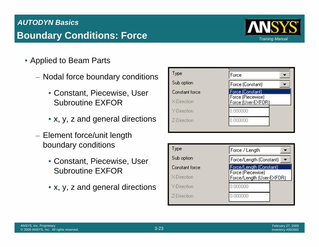
• Applied to Beam Parts
– Nodal force boundary conditions
• Constant, Piecewise, User Subroutine EXFOR
• x, y, z and general directions
– Element force/unit length boundary conditions
• Constant, Piecewise, User Subroutine EXFOR
• x, y, z and general directions
Boundary Conditions: Force

AUTODYN Basics
3-24ANSYS, Inc. Proprietary© 2009 ANSYS, Inc. All rights reserved.
February 27, 2009Inventory #002665
Training Manual
• Applied to Lagrange, ALE and Euler Parts
– Transmits waves through cell faces
– Only the perpendicular component is transmitted
– The impedance of the boundary can be specified
• If impedance is set to zero the impedance of the adjacent cell is used
– The Transmit boundary condition is only approximate and should be placed as far as possible from regions of interest
– For air blast in Euler, Outflow boundary with p = 0.0 is recommended
cI ρ=
Boundary Conditions: Transmit
AUTODYN Basics
3-25ANSYS, Inc. Proprietary© 2009 ANSYS, Inc. All rights reserved.
February 27, 2009Inventory #002665
Training Manual
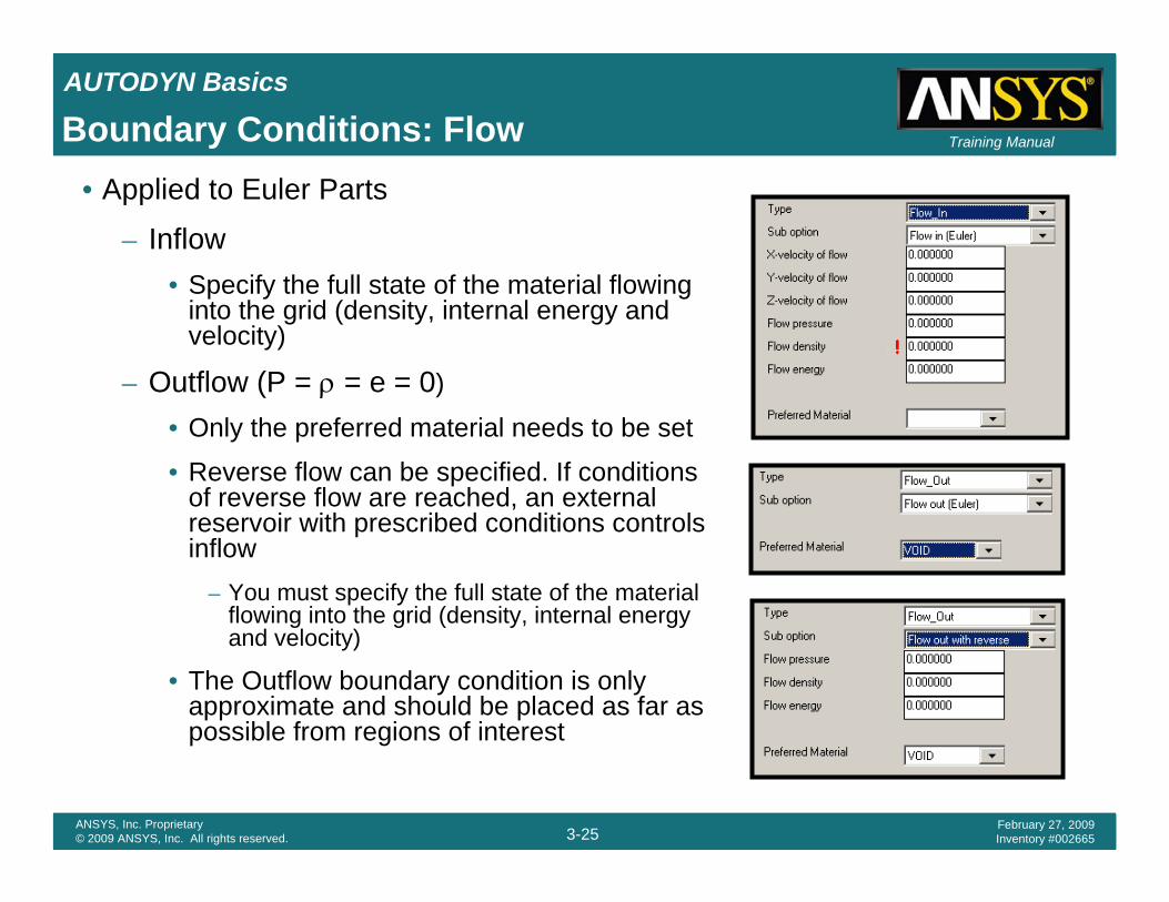
• Applied to Euler Parts
– Inflow• Specify the full state of the material flowing
into the grid (density, internal energy and velocity)
– Outflow (P = ρ = e = 0)
• Only the preferred material needs to be set
• Reverse flow can be specified. If conditions of reverse flow are reached, an external reservoir with prescribed conditions controls inflow
– You must specify the full state of the material flowing into the grid (density, internal energy and velocity)
• The Outflow boundary condition is only approximate and should be placed as far as possible from regions of interest
Boundary Conditions: Flow

AUTODYN Basics
3-26ANSYS, Inc. Proprietary© 2009 ANSYS, Inc. All rights reserved.
February 27, 2009Inventory #002665
Training ManualLagrange Interactions• Options are the same as those used in Explicit
Dynamics (ANSYS)
– Details given in the Body Interactions section of the Explicit Dynamics training course
• Contact type
– Trajectory (default)
• Method (Formulation)– Penalty– Decomposion Response
• Shell Thickness Factor
– External Gap (Proximity Based)
• Gap Size = Pinball Factor
• Parts must be initially separated by the Gap Size

AUTODYN Basics
3-27ANSYS, Inc. Proprietary© 2009 ANSYS, Inc. All rights reserved.
February 27, 2009Inventory #002665
Training Manual
• AUTODYN uses single precision to make optimum use of solver power and memory, so the choice of units is important, particularly for Euler problems
– Avoid pressures below 10-6 of a unit
– Avoid cell masses less than 10-6 of a unit
• The default set of units work well for virtually all problems
– Length mm– Mass mg– Time ms– Velocity m/s– Force mN– Stress kPa– Density g/cm3
– Energy mJ
• Workbench Units will be converted to the chosen AUTODYN units when linked
Units

AUTODYN Basics
3-28ANSYS, Inc. Proprietary© 2009 ANSYS, Inc. All rights reserved.
February 27, 2009Inventory #002665
Training Manual
• Wrapup Criteria
– Must specify Cycle limit and Time limit
– AUTODYN will stop and give warning if energy error exceeds Energy fraction (default 5%)
• Timestep Options
– Defaults are usually OK
– If Initial timestep is left zero, it is computed as half the stability timestep
– If Minimum timestep is left zero, it is computed as 1/10th of the Initial time step
– Safety factor can be safely increased to 0.9 for most Lagrange calculations
Solution Controls

AUTODYN Basics
3-29ANSYS, Inc. Proprietary© 2009 ANSYS, Inc. All rights reserved.
February 27, 2009Inventory #002665
Training ManualConservation Equations• Mass and Momentum
are conserved exactly
• Energy is not conserved exactly
•
– Practical numerical methods which are fully conservative have problems of stability and can be noisy
• Conservation of energy and momentum can be monitored using history plotting features. Good model set-ups and analyses will tend to have low errors
Problem
Good energy conservation

AUTODYN Basics
3-30ANSYS, Inc. Proprietary© 2009 ANSYS, Inc. All rights reserved.
February 27, 2009Inventory #002665
Training Manual
• Save Files / Results Files
– Frequency specified by
• Cycle increment
• Time increment
– Calculation can be re-started from Save files (not Results files)
– Results files are significantly smaller than Save files
– Plots can be created from any Save file or Results file
– Animations can be created from a sequence of Save / Results files
• More flexible than Capture image
Output Controls

AUTODYN Basics
3-31ANSYS, Inc. Proprietary© 2009 ANSYS, Inc. All rights reserved.
February 27, 2009Inventory #002665
Training Manual
• Results Files (3D only)
– Used to create plots• Allows post-processing of large models on
computers with limited resources
– Files are stored in a sub folder, ident_adres
• Base files ident_bcyc.ad_base
– Stores model data required by Results files
– Must be present to load Results file data
• Results files ident_bcyc_ncyc.adres
– bcyc - the cycle number for the Base file
– ncyc - the cycle number for the Results file
Output Controls

AUTODYN Basics
3-32ANSYS, Inc. Proprietary© 2009 ANSYS, Inc. All rights reserved.
February 27, 2009Inventory #002665
Training ManualWorkshop 1: 2D Fragment Impact
Goal:
Model a multi-material cylindrical fragment impacting a plate
Procedure:
Start AUTODYN standalone
Set up the problem in using 2D Axial Symmetry
Solve the problem
View the results
Create animations of the results