8 the stability of ships and ocean vehicles escuela...
TRANSCRIPT

8th International Conference on the Stability of Ships and Ocean Vehicles Escuela Técnica Superior de Ingenieros Navales
743
CROSS-FLOODING DESIGN USING SIMULATIONS
Andrew J. Peters QinetiQ, Haslar Marine Technology Park, (UK) Matthew Galloway QinetiQ, Haslar Marine Technology Park, (UK)
Peter V. Minnick USCG Engineering Logistics Center, Baltimore, Maryland, (USA) Abstract A methodology has been developed for the design of cross-connects on naval vessels, using a time-domain ship motion program. A study of the performance of current cross-flooding system in a United States Coast Guard 270-ft medium endurance cutter class vessel has been compared with an alternative design to demonstrate the approach. A time-domain ship motion program was used that is capable of simulating a damaged vessel with subsequent water ingress and flooding. The program is also capable of modeling passive cross-flooding systems between asymmetrically flooded tanks. This paper compares the performance of the current and an alternative cross-flooding arrangement using the IMO and current USCG criteria for cross-flooding systems in addition to new design guidance based on time-domain analysis. The numerical study used to evaluate the merits and shortcomings of the two cross-flooding systems is discussed. 1. INTRODUCTION
In 1990 the Cooperative Research Navies (CRNAV) Dynamic Stability group was established with the aim of deriving dynamic stability criteria for naval vessels. To derive such criteria, the group needed to evaluate in-service and new ship designs, in moderate to extreme seas in terms of their relative safety and probability of capsize. This would ensure that new vessels continued to be safe, while avoiding high build and life-cycle costs associated with over-engineering. To achieve these objectives the numerical simulation program FREDYN was developed and continues to be applied extensively – both to intact and damaged ships. This time-domain
program is able to take account of nonlinearities associated with drag forces, wave excitation forces, large-angle rigid-body dynamics and motion control devices. The latest version of FREDYN permits investigations into the dynamics of damaged vessels operating in realistic environments, rather than simple pseudo-static analysis, which is the current practice. The current CRNAV group comprises representatives from UK MoD, Naval Sea Systems Command (NAVSEA), the Australian, Canadian, French and the Netherlands navies, as well as the U.S. Coast Guard, Defence Research & Development Canada, (DRDC), Maritime Research Institute in the Netherlands (MARIN), Naval Surface Warfare
8th International Conference on the Stability of Ships and Ocean Vehicles
Escuela Técnica Superior de Ingenieros Navales 744
Center Carderock Division (NSWCCD) and QinetiQ. Longitudinal subdivision is common practice in ship design. This internal arrangement can introduce asymmetric flooding in damage cases which can be resolved in many ways involving improving general stability with solid ballast or with liquid loading restrictions. Cross-flooding systems are regarded as a possible solution to this problem. The effectiveness of cross-flood arrangements fitted to naval ships in a seaway has until recently been little known. This paper describes the investigation into the existing cross-flooding system fitted to the USCG’s 270-ft (Corvette-sized) WMEC ‘Famous’ Class cutters and the assessment of the performance on the vessel after damage. An alternative design of a cross-connect arrangement for this class was made using the state-of-the-art design philosophy and the FREDYN program. Both the current and alternative cross-flooding arrangements were tested and compared to current IMO and USCG criteria for cross-flooding systems. A study was conducted using the FREDYN program in order to compare the time-domain analysis of the current and alternative designs in a systematically broad matrix of conditions. The merits and shortcomings of the two cross-connect arrangements will then be discussed. Static stability analysis of the effectiveness of the cross flooding ducts can be performed using standard static stability software, however, this does not take account of the vessel motions or transient flow after damage. However, large amplitude motion dynamics play an important role in the capsize behavior of a frigate in waves and to the performance of the cross-flooding arrangement fitted. The use of a time-domain simulation program enables the
performance of the cross-flooding ducts to be analysed in a seaway, thus allowing the time taken to achieve cross-flooded equilibrium to be calculated more accurately and transient behaviour to be examined in greater detail. The objective of this paper is to discuss the work that is currently being conducted to assess cross-flooding performance of frigate type ships in waves and wind. This has been developed with the United States Coast Guard. The first findings from this work are presented here. 2. DAMAGE STABILITY CRITERIA & CROSS-FLOODING As with many static-based stability criteria adopted around the world, the origins date back to data and information gathered over many years. This applies especially to the great Pacific Typhoon of December 1944, which struck vessels of USN Pacific Fleet causing the loss of 790 men and three destroyers (see Calhoun, 1981.). Following this incident a review of stability assessment was undertaken, which resulted in new stability criteria for U.S. Navy ships (Sarchin and Goldberg, 1962). This covers the intact and damaged stability criteria, which has been adopted by many Navies around the world including the USCG and UKMoD. Cross flooding systems are now being further investigated within the UKMoD and USCG in order to understand more fully their performance if employed to improve the damage stability characteristics of a vessel. 2.1 DDS 079-1 Criteria The U.S. Navy stability criteria are documented in the Design Data Sheet (DDS) 079-1 (U.S. Navy, 1975), which is divided into criteria for damage

8th International Conference on the Stability of Ships and Ocean Vehicles Escuela Técnica Superior de Ingenieros Navales
745
stability for both side protected and non-protected vessels. The non-protected criteria relate to the 270-ft cutter that is the vessel used in this investigation. The DDS 079-1 states that an angle of less than 15 degrees is required after damage for operational requirements. There is no mention of cross-flood systems except for in the side protected vessels which states that the maximum list shall not exceed 20 degrees and that arrangements exist for rapidly reducing the list to less than 5 degrees. It does not specify any time constraints for this. 2.2 Current USCG Criteria From the current USCG Design and Construction Standard (DCS) SWBS 079 on the use of "Cross-Connection of Tanks" it states "cross-connection of tanks should only be employed where other alternatives have been evaluated and are deemed impracticable. It then goes on to state that where cross-connection of tanks is utilized, the following applies: • The cross-flooding system shall prevent
transference of liquids from one tank to the other during normal rolling of the ship.
• Cross-flooding time shall not exceed five minutes
• Prior to cross-flooding the following criteria shall be met:
• Heel shall not exceed 20 degrees • Area A1/A2 greater than or equal to 1.4 The 1960 SOLAS conference first laid out the requirements for cross-flooding systems where a maximum time for cross-flooding was defined as 15 minutes. This limit was probably based on information available at the time. This criteria is now included in the current regulations as Regulation 8 (5) in Chapter 2 Part B of the International Convention for the
Safety of life at sea (SOLAS). This criteria for cross-flooding is stated as follows: 5. Unsymmetrical flooding is to be kept to a minimum consistent with efficient arrangements. Where it is necessary to correct large angles of heel the means adopted shall, where practical, be self-acting, but where controls to cross-flooding fittings are provided they shall be operable from above the bulkhead deck. These fittings shall be acceptable to the Administration. The maximum angle of heel after flooding but before equalisation shall be less than 15 degrees. Where cross-flooding fitting is required the time to equalisation shall not exceed 15 min. Suitable information concerning the use of the cross-flooding fitting shall be supplied to the master of the ship. The criteria goes on to state that for the unsymmetrical case that the angle of heel after equalisation has completed should be less than 12 degrees for two or more compartment damage. Cross-flooding systems should be regarded as a means to improve the damage stability characteristics of a vessel, but there is always the risk that any cross-flooding system may not be totally reliable. No one cross-flooding arrangement is right for all situations. A design arrangement should be extensively examined to see how it would operate in an intact and damaged compartment to identify potential problems. 3. NUMERICAL MODELLING
FREDYN was designed to enable the simulation of motion of an intact steered ship in wind and waves. Unlike the currently available frequency-domain programs, FREDYN is able to take account of the non-linearities associated with the drag forces, excitation forces and rigid-body dynamics. The approach is a physical one, where all factors are
8th International Conference on the Stability of Ships and Ocean Vehicles
Escuela Técnica Superior de Ingenieros Navales 746
considered. Non-linearities have to be considered as they arise from • Effect of large angles on excitation forces, • Rigid-body dynamics with large angles, • Drag forces associated with hull motions,
wave orbital velocities and wind, or • Integration of wave induced pressure up to
free surface. The latest version of FREDYN can model vessels with damaged compartments and cross-flooding ducts, and can predict the vessel’s behavior in waves. 3.1 Extreme motions of damaged ship
The theory for predicting the large amplitude motions with FREDYN has been described by McTaggart and De Kat (2000) and by Van ’ t Veer and De Kat (2000). The derivation of the equations of motions for a ship subjected to flooding through one or more damage openings is based on the conservation of linear and angular momentum for six coupled degrees of freedom and described by De Kat and Peters (2002). Here the fluid inside the ship is considered as a free particle with concentrated mass; using this approach classical rigid body dynamics can be used to derive the equations of motion. 3.2 Water ingress and fluid loading
Hydraulic flow To estimate the flow rates of water entering a compartment, the flooding model is based on the Bernoulli equation (see Van ’t Veer and De Kat, 2000). This analysis is applied to each damage opening or holes between two compartments. It assumes stationary flow
conditions and no loss of energy due to friction or increased turbulence. Based on the difference in pressure head, the velocity through a damage opening can be calculated. In addition, airflow and compression effects are modelled using the appropriate gas laws. To obtain the total discharge through an opening, the following empirical formulation is used:
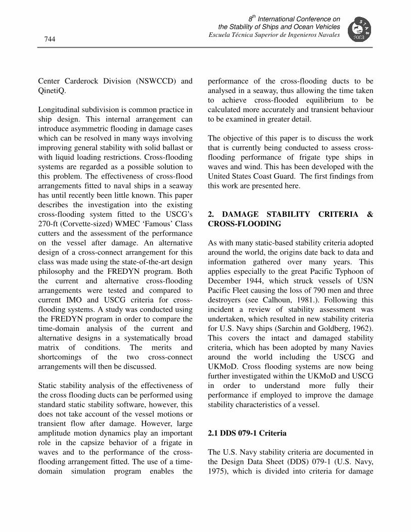
d 2Q C v A= (1) where A is the area of the opening and dC is the discharge coefficient. This coefficient accounts for a combination of several effects (such as friction losses). Cross-flooding ducts are modelled in a similar way to this but account is taken of the friction in the pipe. Quasi-dynamic fluid loading Based on the computed inflow and outflow of fluid through all openings, the fluid mass inside a shipboard compartment is known at each time step. A simple yet practical approach is to assume that the water level of the floodwater inside any compartment remains horizontal (earth-fixed) at all times. This implies that the damage fluid causes a vertical force (due to gravity) to act on the ship and that any sloshing effects are neglected. Shown in Figure 1 is a comparison of previous cross-flooding validation between a FREDYN prediction and an experiment of a damaged Leander class frigate operating in a seaway (De Kat and Peters, 2002). This work demonstrated that the simulation program FREDYN effectively modelled the motions of a ship with cross-flooding systems operational.
8th International Conference on the Stability of Ships and Ocean Vehicles Escuela Técnica Superior de Ingenieros Navales
747
Comparison of Fredyn vs the Experiment Data for Roll Angle in SS4 with Cross Flooding and KG = 5.111m
-10
-5
0
5
10
15
20
25
30
0 200 400 600 800 1000 1200 1400 1600 1800 2000
Time (s) [Ships scale]
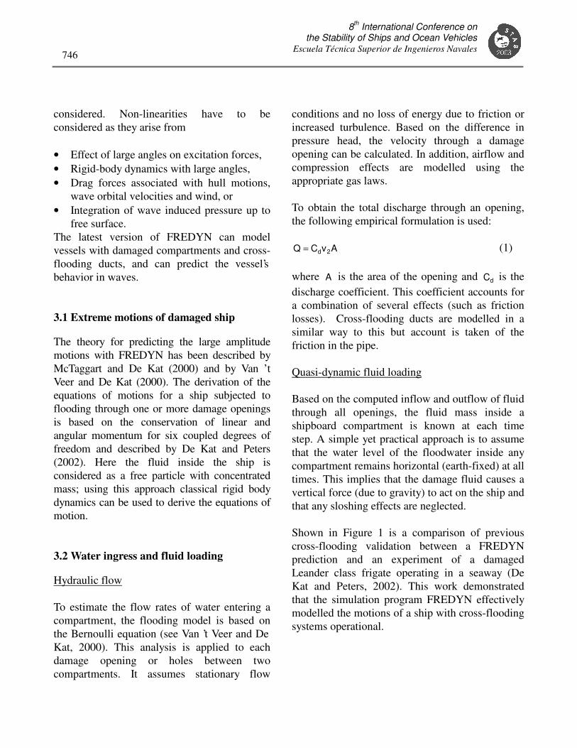
Fredyn Experiment Run Figure 1 – Comparison of experiment and simulated roll in a mean sea state 4 3.3 Model Generation for Current Study Two computer models of the USCG 270-ft medium endurance cutter (WMEC) were required to perform simulations; the basic static stability model and the FREDYN dynamic stability model. A static stability model was required to provide the basic hydrostatic inputs for FREDYN; it also serves as a benchmark test to validate the FREDYN model. Paramarine was chosen as the software for which the static stability model would be produced. The Graphics Research Corporation (GRC) develops Paramarine with specific funding from the UKMoD. QinetiQ (Haslar) has rigorously tested and validated Paramarine against pure mathematical models, which gives confidence in the algorithms and equations used. This work was performed on the behalf of the UKMoD. The hull definition (see Figure 2) was generated from a surface fit of curve geometry data provided by the USCG. The surface fit operation in Paramarine automatically provides a good match to the curve data; however, some manual fairing was performed to remove any inflexion points.
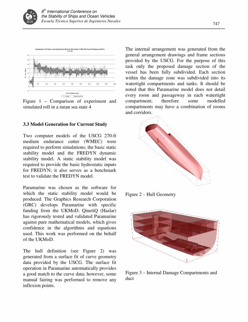
The internal arrangement was generated from the general arrangement drawings and frame sections provided by the USCG. For the purpose of this task only the proposed damage section of the vessel has been fully subdivided. Each section within the damage zone was subdivided into its watertight compartments and tanks. It should be noted that this Paramarine model does not detail every room and passageway in each watertight compartment; therefore some modelled compartments may have a combination of rooms and corridors.
Figure 2 – Hull Geometry
Figure 3 – Internal Damage Compartments and duct

8th International Conference on the Stability of Ships and Ocean Vehicles
Escuela Técnica Superior de Ingenieros Navales 748
The USCG 270-ft WMEC is fitted with a cross-flooding system connecting clean ballast tank 4-103-1-W with clean ballast tank 4-103-2-W. The cross flooding duct was modelled in Paramarine to help visualise its complex shape, however, this detail was not used in the subsequent stability analysis. The cross flooding arrangement is shown in Figure 3.
The internal compartments were subject to validation to UKMoD standards for computer models (SSP24) where data existed, e.g., tanks. The standards require the compartment volumes to be within 2%, and the vertical centre of gravity to be within 1%. There are no criteria set for compartment longitudinal and transverse centre of gravity, as these are deemed less important. As this study involves asymmetrical damage the transverse centre of gravity of the compartments is of great importance, therefore a 1% criteria for the transverse centre of gravity was introduced. In order to accurately model the cross-flooding ducts, a flow coefficient is required to incorporate the friction effects in the duct. This flow coefficient is required to ensure that the ducts model flow in a realistic manner. The coefficients were calculated based on standard practice for flow in pipes. This method accounts for the size and length as well as the shape of the duct. In selecting a coefficient extreme care was taken as this can greatly affect the flow. Previous work by Peters (2001) has shown that if carefully selected this approach provides accurate simulations in comparison to experimental data. A sensitivity study was completed on the selected coefficients for each duct to ensure valid calculations with small changes to the coefficients.
3.4 Cross-flooding Modeling in FREDYN Defining an accurate cross-flooding system for use when running FREDYN involves careful detailing to ensure realistic modeling. The x, y and z position of the openings of the duct are defined and so is the cross sectional area of the pipe. The flow coefficient for the pipe is derived from using standard values mentioned above based on dimensions and shape of the duct. This was shown to sufficiently accurate when used in FREDYN when compared with experiment data (Peters, 2001). For cross flooding ducts that have the openings at the highest point in the pipe run, modeling is straightforward. For pipes that have a section of the duct that is higher than the openings, as in the inverted U-duct, additional modeling is required to accurately model this. To model the existing cross-flood pipe as currently fitted to the 270-ft WMEC involves modeling the duct in three parts. Firstly, at the position of the highest point of the duct, a very small ‘virtual’ tank is created close to the size of the duct cross-section. The first duct is input with the tank opening defined on the one end and the virtual tank defined on the other end. The coefficients in this duct then take into account the length and bends in this part of the duct. A second duct then is defined between the virtual tank and the cross-flooding tank. Again the coefficients are defined for that part of the duct. This ensures that the vertical path of the water in the pipe is taken account of and that the flooding will occur as for the real duct.
3.5 Alternative Duct Design In addition to the current cross-flooding arrangement, an alternative design was created

8th International Conference on the Stability of Ships and Ocean Vehicles Escuela Técnica Superior de Ingenieros Navales
749
using the guidelines listed above and results from simulations using the FREDYN program. The chosen design was based on a duel-duct design, as this configuration was deemed suitable for this tank layout (see Figure 4). This pipe system joins the top of each tank to the bottom of the other. The diameter of each of the two ducts was smaller than that of the current duct as it is expected that both ducts would cross-flood simultaneously and would be demonstrated in the simulations. Due to their position inside the tank, the ducts have a slight curvature to them so there will be less restriction to the flow within each pipe.
Figure 4 – Duct Designs They are also shorter than the current design. The performance before fine-tuning was demonstrated in the matrix of runs. The results highlight where improvements to both designs could be made.
A list of parameters was compiled of what could effect the performance of the ship following damage and hence how it may effect the cross-flooding system. These were included in a matrix of runs to assess the current and alternative duct performance. Speed was also included to investigate if this improved the situation for the ship after damage. The matrix was selected not only to thoroughly investigate
the ducts but to also to provide some guidance to the operator on heading and speed selection after damage, if available, and how it may affect the vessels behavior. 3.6 Run Selection To conduct the entire run set through all combinations of the initial selected initial variables would have resulted in over 8000 simulations. This was deemed unnecessary to investigation. Instead a rational parametric search was planned such that the effects of each significant change in the variables could be determined. Each run set of runs in the table below concentrates on a particular part of the matrix with the number of runs set so data trends can be deduced.
Table 1 - Matrix of conditions investigated
The first set of runs in the table, Run Set 1, aimed to assess the performance without cross-flooding, the current design and an alternative design performance with the ship at different speeds and orientation to the waves while the other variables were kept constant. This allowed an assessment of the effect of heading and speed on the performance
Parameter /Matrix
Run Set 1
Run Set 2
Run Set 3
Run Set 4
Loading Condition
1 2 1 1
Cross-flood systems
3 3 3 2
Speeds 3 1 3 1
Headings 7 3 2 1
Sea Conditions
1 3 5 1
Damage Occurrence
1 1 1 3
Repeats 1 1 1 3
TOTAL 63 54 90 18

8th International Conference on the Stability of Ships and Ocean Vehicles
Escuela Técnica Superior de Ingenieros Navales 750
on each of the cross-flooding systems to be made. The zero speed/no cross-flooding case has been used as a baseline case to identify where the situation is improved. The second set, Run Set 2, was selected to assess the effect of ship loading condition on the performance of three cross-flooding systems. The selection tested two different ship conditions at three headings and in three sea conditions to allow the performance to be assessed. The third set, Run Set 3, was selected to assess the effect of sea state on the performance of the cross-flooding systems. In this set the non-cross-flooding situation, the current design and an alternative design were tested in a range of wave conditions at three speeds in beam seas (opening towards and away from the waves). This demonstrated how the cross-flooding performance is affected in different sea conditions as the ship motions increased. It also identified the issues that occur at slow forward speed following damage The aim of Run Set 4 was to evaluate the effect of the ship’s position on the wave to establish how orientation effects the initial damage transients for the non cross-flooding and cross-flooding cases. Repeat runs were also been conducted at different points in the wave realization (damage initiating on top of a wave crest, in a trough, or in a quiescent location between larger wave groups) to investigate how that effected the ship behavior. 3.7 Ship Condition The current loading conditions of this class did not provide an interesting case as all of the
damage criteria were met and the static list angles were less than 15 degrees. Consequently, minor modifications were made so that the final list angle after damage was increased to just over the current 15 degrees criteria limit (USCG and SOLAS). The stores were lowered in permeability to 60% representative of a full store. The engine room was also reduced slightly in permeability to 75%. The diesel oil service tanks were also lowered to 25% full. The KG was then raised by 1.8% to give a list angle of 17.5 degrees. This gave a more suitable condition in which to test cross-flooding designs. For Run Set 3 a second condition was required which was basically a minimum operating condition. In this condition, the two ballast tanks that cross-flood are both pressed full. To create a suitable condition for the tests the two ballast tanks were emptied, which caused a list angle greater than required. The KG was then lowered by 3 inches to give a list angle close to 19 degrees. This condition is sufficiently different to the deep condition to investigate the effect that ship condition has on the performance of the cross-flooding systems.
3.8 Cross-flooding design One of the advantages of a time-domain simulation tool and the ability to input, modify and change ducts rapidly is that it allows the simulation program to be used as a design tool for designing/improving cross-flooding design. The following points give some guidance for consideration while designing a cross-flooding system. These points were derived during this study and previous work (Peters, 2001). They first main point that should be noted is that cross flooding reduces the reserve of buoyancy on the intact side of the ship. This should be
8th International Conference on the Stability of Ships and Ocean Vehicles Escuela Técnica Superior de Ingenieros Navales
751
investigated to ascertain whether cross flooding would firstly be beneficial or not. Cross flooding could, in an extreme case, cause a ship to sink further and reduce waterplane area, substantially reducing stability and lowering downflooding points closer to the waterline. Cross-flooding systems should be designed passive/automatic where possible, which is the case for the current and alternative designs. When cross flooding involves human intervention or additional machinery/pumps then the time to operate is increased, as is the risk of the system not operating effectively. An active system will not begin operation during the critical seconds immediately following damage. A straight-duct system is the most simple of solutions for a cross-flooding ideal for connecting the lowest points of two empty tanks, void spaces etc. but if it is used to connect two fuel tanks there is likely to be constant mixing of tanks. This is also undesirable if the ship sustains asymmetric damage elsewhere in the vessel then the full fuel tanks can drain freely under gravity into the tank on the lower side, thus degrading stability. The current duct design does have a vertical section to the pipe to reduce the opportunity for the tanks to mix. The alternative duel-duct option is set up to reduce tank mixing by connecting the upper part of the tank to the lower part of the other. The two tanks connected in the 270-ft WMEC are well below the waterline and remain pressed full of floodwater in all but the largest sea conditions. Where possible, cross-flooding systems should be fitted in regions where the compartments will fill completely after damage and, if possible, remain pressed full even
during rolling. This reduces problems associated with additional free-surface effects and cross-flooding effectiveness. In the current design there is a vertical section to the cross-connect to reduce the chance of tank mixing but this higher section of the pipe run raises the duct closer to the free surface that can rise above the waterline and stop the cross-flooding. The alternative design has also been positioned so as to reduce the chance of the duct opening emerging above the waterline. All parts of the duct route should be below damaged waterlines at all times and the highest part of the duct must be formed in a way so that none of the duct rises above the waterline at any time after damage. If the duct rises above the waterline, for example during the transient roll, then cross flooding will not initiate until the duct submerges below the waterline. Design studies and model experiments at Haslar have shown that even the initial transient roll is fractionally reduced with cross-flooding systems that initiate immediately after damage. FREDYN-based time-domain simulations during previous studies (not reported here) have highlighted the case where a wider ship, with a duct opening in the centre of the side tanks, rolled after damage to an angle so as to raise the end of the duct above the water, stopping completely any flow into the far side tank. In the cases tested in this study the contents of both cross-connected tanks are the same, ballast water. If cross flooding is to connect two tanks together then the tanks should contain the same type of contents, as there will definitely be some mixing with passive cross-flooding systems at some time. Duct design should incorporate elements so as to reduce mixing of tanks, so also reducing the potential sloshing between tanks. Current designs often have openings at the top of the tanks or a

8th International Conference on the Stability of Ships and Ocean Vehicles
Escuela Técnica Superior de Ingenieros Navales 752
curved connection to restrain cross flooding. The design to stop or restrain the mixing of tanks must not reduce the effect of the ducts if damage is sustained. 3.9 Duct Routing and Sizing It was found in a previous study (Peters, 2001) that the duct diameter should not be lower than 0.25 m, even in small tanks, and preferably should be as large as practically possible for the compartment. Duct sizes should be physically or computationally modeled to assess any potential free-surface or stability problems during the cross-flooding stage. The ducting should be the shortest possible length and contain as few bends and valves as possible to reduce frictional losses. The original cross-flooding duct used in the 270-ft WMEC, which can be just seen in Figure 2, has many bends and high angles and is 12.75 inches (0.324m) in diameter. 3.10 Duct positioning In both the duct designs examined the pipe openings and pipe runs should be positioned so they remain below the waterline during the intact, transient and damage phases to ensure immediate and effective cross-flooding. Other considerations should be made in the positioning of the pipe run to reduce the risk of damage to the cross-flooding arrangement during the damage event. For bottom and side tanks, where the risk of collision damage is highest, the ducts have been positioned as far as possible from the shell plating to ensure the duct itself does not get bent or blocked during damage. Duel-type ducts, that follow closely the side plating,
should be positioned preferably at each end of the compartment near the bulkheads, if possible, so as to offer some protection to the ducts during the damage incident. The duel-type duct has the disadvantage that it requires the complexity of two pipes to be fitted, although in cases tested in this project often there is flooding through both ducts thus increasing the rate of cross-flooding and providing an element of redundancy in the system. 3.11 Effects of through-life growth In the tests two different conditions were tested to ascertain how the change in condition could affect the cross-flood system performance. The chosen design of cross-flooding system should be analysed at a range of expected through-life conditions for the vessel. This is to ensure that as KG and displacement grow, the ducts would still operate effectively. The condition later in life may result in, for example, part of the duct rising above the waterline stopping cross-flooding where this may not have been the case in an earlier condition. 4. RESULTS AND CONCLUSIONS Dynamic stability cross-flooding simulations allowed the effectiveness of the cross-flooding ducts to be thoroughly investigated. This time-domain analysis allowed the performance of the cross flooding to be assessed and the time taken to cross flood to be calculated with the vessel motion taken into account. This is opposed to the purely static stability calculations, which assumed calm water for the entire process. This gives a better insight into how the cross-flooding ducts operate at sea and their effect on the vessel during and after damage.

8th International Conference on the Stability of Ships and Ocean Vehicles Escuela Técnica Superior de Ingenieros Navales
753
Heading Vs Time to Cross-flood - USCG Duct
00.5
11.5
22.5
33.5
4
0 90 180 270 360
Heading (degs)
Tim
e (m
ins)
USCG Duct @ 12kts-0Kts
USCG Duct @ 7kts-0Kts
USCG Duct @ 7Kts-7Kts
Figure 5 – Time to cross-flood – existing duct
Heading Vs Time to Cross-flood - QinetiQ Duct
00.5
11.5
22.5
33.5
4
0 90 180 270 360
Heading (degs)
Tim
e (s
ecs)
QinetiQ Duct @ 12kts-0Kts
QinetiQ Duct @ 7kts-0Kts
QinetiQ Duct @ 7Kts-7Kts
Figure 6 – Time to cross-flood – redesigned
duct
Both of the cross-flooding systems investigated pass the current criteria examined in this paper. The times to cross flood versus ship heading are given in Figures 5 and 6 for both systems. From IMO, the time to cross flood is less than 15 minutes, where the USCG defines 5 minutes to cross flood. The heel angle in the conditions tested also reduced the mean heel after damage to the order of 10 degrees, which also passes the current criteria. The redesigned duct showed a time for cross flooding almost half that of the current design (see Figure 6), though the pipe diameters were less than that of the current design. Two ducts are used in this system and in nearly every case both ducts contributed to the counter flooding, which decreases the time to complete cross flooding. Due to the rapid flooding, the initial
large transient rolls were also reduced in comparison to the no-duct case. The pipe run of the redesigned duct has only a sight curvature to it thereby allowing as free flow as possible, unlike the current design which incorporates multiple tight bends.
Heading Vs Transient Roll Angle at 7Kts Before Damage 0Kts after Damage
0
10
20
30
40
0 90 180 270 360
Heading (degs)R
oll
An
gle
(d
egs)
No Duct @ 7Kts-0Kts
USCG Duct @ 7Kts-0Kts
QinetiQ Duct @ 7kts-0Kts
Figure 7 – Transient roll angle – 7Kts before damage 0Kts after
Heading Vs Transient Roll Angle at 7Kts Before Damage 7Kts after Damage
0
10
20
30
40
0 90 180 270 360
Heading (degs)
Ro
ll A
ng
le (
deg
s)
No Duct @ 7Kts-7Kts
USCG Duct @ 7Kts-7Kts
QinetiQ Duct @ 7kts-7Kts
Figure 8 - Transient roll angle – 7Kts before damage 7Kts after
Heading Vs RMS Roll Angle at 7Kts Before Damage 0Kts after Damage
0
5
10
15
20
0 90 180 270 360
Heading (degs)
RM
S R
oll A
ng
le
(deg
s) No Duct @ 7Kts-0Kts
USCG Duct @ 7Kts-0Kts
QinetiQ Duct @ 7kts-0Kts
Figure 9 - RMS roll angle – 7Kts before damage 0Kts after

8th International Conference on the Stability of Ships and Ocean Vehicles
Escuela Técnica Superior de Ingenieros Navales 754
Heading Vs RMS Roll Angle at 7Kts Before Damage 7Kts after Damage
02
46
810
12
0 90 180 270 360
Heading (degs)
RM
S R
oll
An
gle
(d
egs) No Duct @ 7Kts-7Kts
USCG Duct @ 7Kts-7Kts
QinetiQ Duct @ 7kts-7Kts
Figure 10 - RMS roll angle – 7Kts before damage 7Kts after In the situation of the ship with speed prior to the damage and zero speed afterwards, there appeared to be little or no difference as compared to the zero-speed case, as the speed was quickly lost and the control of heading was lost. The cases with the ship continuing on at 7 Kts after damage showed an improvement in the transient and RMS motions after damage (see Figures 7 through 10). This is due to the anti-roll stabilisers remaining effective and reducing the roll even after damage. The transient roll was often seen to be worse in head seas than in beam seas, probably due to the position of the wave trough at the point of damage. Once past the transient roll, the 7 Kts into head seas case resulted in the lowest RMS roll motion after damage, for the duct and no-duct cases (see Figure 10).
The transient roll after damage depended more on the wave itself rather than the point on the wave where the damage occurred. An exploration of different damage initiation times within the same seaway showed variations of only 4 degrees in the transient roll angle. A run plan as presented above has shown to provide a suitable test matrix in which to evaluate the performance of existing and new designs. This ensures that the performance
meets the requirements in wide selection of scenarios. It has been shown that following this methodology and using a suitable time-domain code that an effective cross-flooding arrangement can be designed to ensure an effective operation in all conditions and including all transient effects from the onset of damage through the point of equilibrium flooding 5. ACKNOWLEDGEMENTS The authors would like to gratefully acknowledge the permission granted by the USCG Engineering Logistics Center for publishing the results of the investigation. 6. REFERENCES [1]. Calhoun, CAPT C. Raymond Calhoun, USN (ret.), “Typhoon: The Other Enemy - The Third Fleet and the Pacific Storm of December, 1944”, Naval Institute Press, Annapolis, Maryland, 1981. [2]. De Kat, J.O., Peters A.J. “Damage Stability of Frigate Sized Ships”, International Maritime Association of the Mediterranean Conference, Crete, 2002 [3]. De Kat, J.O., Kanerva, M., Van ’t Veer, R. and Mikkonen, I., “"Damage Survivability of a New Ro-Ro Ferry”, Proceedings of the 7th International Conference on Stability for Ships and Ocean Vehicles, STAB 2000, Launceston, Tasmania, Feb. 2000 [4]. McTaggart, K. and De Kat, J.O., “Capsize Risk of Intact Frigates in Irregular Seas”, Transactions SNAME, 2000

8th International Conference on the Stability of Ships and Ocean Vehicles Escuela Técnica Superior de Ingenieros Navales
755
[5]. MoD Defence Standard 02-109 (NES 109), UK Ministry of Defence, Stability Standards for Surface Ships, Part 1, Conventional Ships, 2000 [6]. Peters A.J “Cross -flooding of Frigate Sized Vessels” March 2001 – Commercial in confidence - USCG and the UK MoD [7]. Sarchin, T.H. and Goldberg, L.L., “Stability and Buoyancy C riteria for US Naval Surface Ships”, Transactions SNAME, 1962 [8]. SOLAS Consolidated Edition, 2001, International Maritime Organization, London, 2001
[9]. U.S. Navy, Naval Ship Engineering Center, Design Data Sheet – Stability and Buoyancy of U.S. Naval Surface Ships, DDS 079-1, U.S. Navy, currently Naval Sea Systems Command, Washington, DC, 1 August 1975. [10]. Van ’t Veer, R. and De Kat, J.O., “Experimental and Numerical Investigation on Progressive Flooding and Sloshing in Complex Compartment Geometries”, Proceedings of the 7th International Conference on Stability for Ships and Ocean Vehicles, STAB 2000, Vol. A, Launceston, Tasmania, Feb. 2000, pp. 305-321 © Copyright QinetiQ Limited 2003

8th International Conference on the Stability of Ships and Ocean Vehicles
Escuela Técnica Superior de Ingenieros Navales 756