8 bit floating point adder/ subtractor - harvey mudd...
TRANSCRIPT

1
Final ReportIntro to CMOS VLSI Design
E158
8 Bit Floating Point Adder/ Subtractor
11 April 2001Andrew Ingram
Ronalee Lo

2
Table of ContentsSection page
Color Chip Plots 1
Functional Overview 2-3
Chip Floorplan 4-5
Area and Design Time Data 6
Simulation Results 71) Verilog waveforms 8-132) IRSim simulation 14-16
Verification Results 17
Postfabrication Test Plan 18-25
Schematics/ Verilog 261) Readable Verilog Code 26-362) Verilog Code for Electric 37-473) Leaf Cell: Mux2 (schematic) 484) Leaf Cell: Full adder (schematic) 485) Hand layout of the Exponent Bitslice (schematic) 496) Hand layout of Exponent Datapath (schematic) 497) Synthesized and hand layout of full datapath (schematic) 50
Layout1) Leaf Cell: Mux2 (layout) 512) Leaf Cell: Full Adder (layout) 513) Hand layout of Exponent Datapath (layout) 524) Synthesized and hand layout of full datapath (layout) 52

3
Color Chip Plot
4
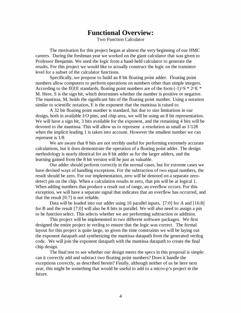
Functional Overview:Two Function Calculator
The motivation for this project began at almost the very beginning of our HMCcareers. During the freshman year we worked on the giant calculator that was given toProfessor Benjamin. We used the logic from a hand-held calculator to generate theresults. For this project we would like to actually construct the logic on the transistorlevel for a subset of the calculator functions.
Specifically, we propose to build an 8 bit floating point adder. Floating pointnumbers allow computers to perform operations on numbers other than simple integers.According to the IEEE standards, floating point numbers are of the form (-1)^S * 2^E *M. Here, S is the sign bit, which determines whether the number is positive or negative.The mantissa, M, holds the significant bits of the floating point number. Using a notationsimilar to scientific notation, E is the exponent that the mantissa is raised to.
A 32 bit floating point number is standard, but due to size limitations in ourdesign, both in available I/O pins, and chip area, we will be using an 8 bit representation.We will have a sign bit, 3 bits available for the exponent, and the remaining 4 bits will bedevoted to the mantissa. This will allow us to represent a resolution as small as 1/128when the implicit leading 1 is taken into account. However the smallest number we canrepresent is 1/8
We are aware that 8 bits are not terribly useful for performing extremely accuratecalculations, but it does demonstrate the operation of a floating point adder. The designmethodology is nearly identical for an 8 bit adder as for the larger adders, and thelearning gained from the 8 bit version will be just as valuable.
Our adder should perform correctly in the normal cases, but for extreme cases wehave devised ways of handling exceptions. For the subtraction of two equal numbers, theresult should be zero. For our implementation, zero will be denoted on a separate zero-detect pin on the chip. When a calculation results in zero, that pin will be at logical 1.When adding numbers that produce a result out of range, an overflow occurs. For thisexception, we will have a separate signal that indicates that an overflow has occurred, andthat the result [0:7] is not reliable.
Data will be loaded into our adder using 16 parallel inputs, [7:0] for A and [16:8]for B and the result [7:0] will also be 8 bits in parallel. We will also need to assign a pinto be function select. This selects whether we are performing subtraction or addition.
This project will be implemented in two different software packages. We firstdesigned the entire project in verilog to ensure that the logic was correct. The formallayout for this project is quite large, so given the time constraints we will be laying outthe exponent datapath and synthesizing the mantissa datapath from the generated verilogcode. We will join the exponent datapath with the mantissa datapath to create the finalchip design.
The final test to see whether our design meets the specs in this proposal is simple:can it correctly add and subtract two floating point numbers? Does it handle theexceptions correctly, as described herein? Finally, although neither of us be here nextyear, this might be something that would be useful to add to a micro-p’s project in thefuture.

5
Inputs OutputsA[0:7] Result[0:7]B[0:7] Zero detectClk OverflowFunction selectPowerGround

6
Chip Floorplan: Block Diagram
7
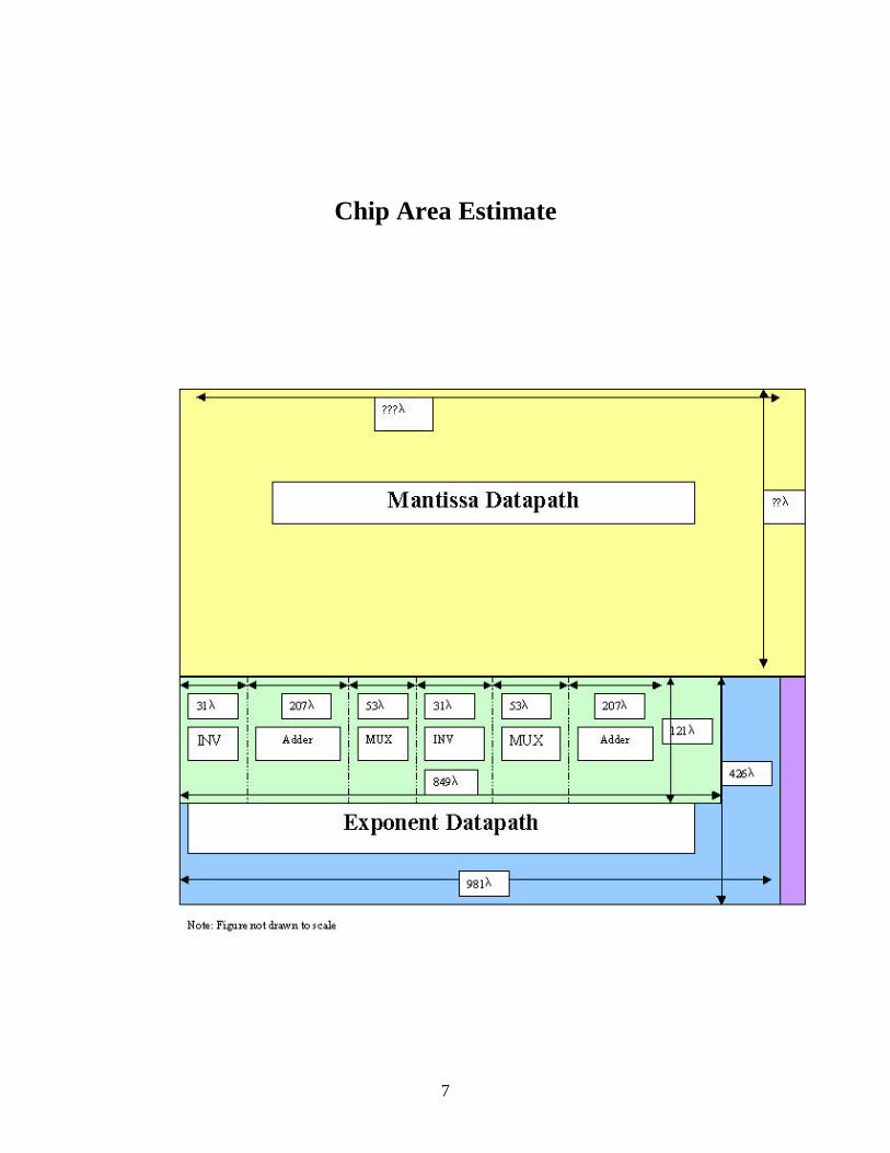
Chip Area Estimate

8
Area and Design Time DataCell Name Area Design Time Comments2-Input Mux 4982λ2 1 hour Modified a design found in
an existing libraryINV 3007λ2 5 minutes Taken from another libraryAdder 20286λ2 4 hours Metal modifications to an
existing designExponent Bitslice 102729λ2 9 hours Assembled various parts,
required a lot of updating asdesigns changed
Exponent Datapath 477252λ2 3 hours Assembled bitslices, alsotook a lot of updating andmodifications
Synthesized Datapath NA See below
Complete layout NA
Other Time ConsiderationsTask Time CommentsConceptual Design 8 hours Visualizing the data path, identifying
the inputs and outputs to each module
Verilog Code 40-45 hours Many attempts to get a working code.Had to gain a clear understanding ofhow a floating-point adder works.Commenting and rewriting code toaccommodate Electric
Verification of Exponent Datapath 4 hours Getting DRC, ERC, and NCC to pass inElectric for the hand-layout of theexponent datapath layout andschematic. Some time was spent tryingto get NCC to pass in Electric but endedup verifying using Gemini.
Simulation of Exponent Datapath 14 hours Electric has a lot of trouble generating a.sim file for both the layout andschematic datapath, see Simulationsection for more details
Synthesize Mantissa Datapath 7 hours Design Analyzer could not make a non-hierarchical .vhdl file for Electric
Final Report 10 hours

9
Simulation Results
Many simulation tests were performed on this project during various stages in thedevelopment. The first set of waveforms following this section is the simulation done onthe complete Verilog code using the Xilinx simulation tool. The complete code includesboth the exponent and mantissa datapaths. By proving that the code is simulatingproperly, we are fairly confident that the synthesized mantissa datapath will be correct,but that we can also use the exponent datapath code as a guide for the hand drawnexponent datapath. We tested the code with all of the cases listed in the testing protocol.

10

11

12

13

14

15
16
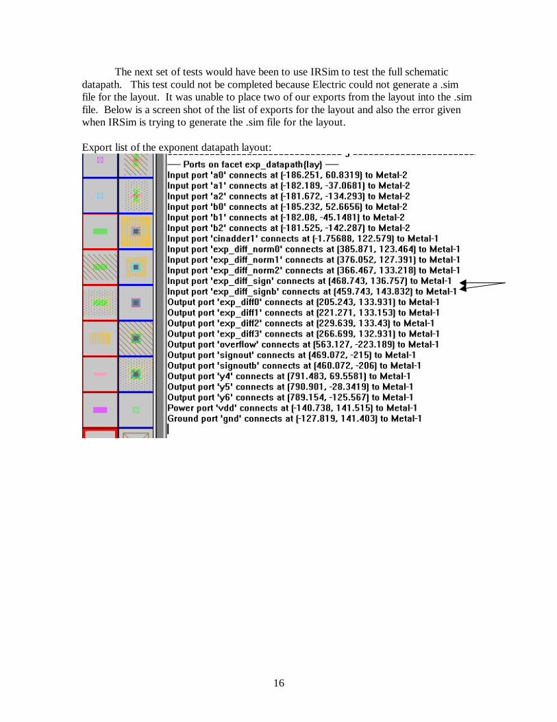
The next set of tests would have been to use IRSim to test the full schematicdatapath. This test could not be completed because Electric could not generate a .simfile for the layout. It was unable to place two of our exports from the layout into the .simfile. Below is a screen shot of the list of exports for the layout and also the error givenwhen IRSim is trying to generate the .sim file for the layout.
Export list of the exponent datapath layout:
17
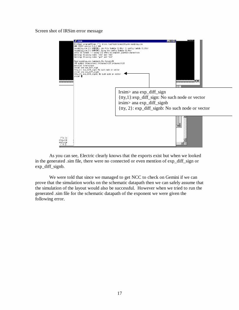
Screen shot of IRSim error message
As you can see, Electric clearly knows that the exports exist but when we lookedin the generated .sim file, there were no connected or even mention of exp_diff_sign orexp_diff_signb.
We were told that since we managed to get NCC to check on Gemini if we canprove that the simulation works on the schematic datapath then we can safely assume thatthe simulation of the layout would also be successful. However when we tried to run thegenerated .sim file for the schematic datapath of the exponent we were given thefollowing error.
Irsim> ana exp_diff_sign{tty,1}:exp_diff_sign: No such node or vectorirsim> ana exp_diff_signb{tty, 2}: exp_diff_signb: No such node or vector

18
Screen shot of IRSim message window
Since neither datapath was able to generate a proper .sim file, the full datapathcould not be simulated. We attempted to track down the bug which prevented Electricfrom generating a correct .sim file. We check other facets such as INV and AND usingIRSim to simulate their functionality. Both gates simulated properly. In the end we stillcould not find the problem.
Too many errors in sim file <expdpsch.sim>

19
Verification Results
DRC, ERC, and NCC verification was done in separate stages as our projectprogressed. We verified DRC, ERC, and NCC on many smaller layouts and schematicsto make sure that our design was not going awry without us realizing it. DRC, ERC, andNCC passed on the MUX and Adder. We also verified DRC and ERC on the exponentdatapath bitslice. However, we ran into some problems when we tried to verify NCC.We eventually used Gemini to determine why NCC was not passing. We also usedGemini to verify NCC on the full datapath of the exponent layout and schematic. Geminidid identify minor modifications that needed to be made to our design. However, eventhough Gemini verified both the bitslice and the datapath, Electric would not pass NCCon either. We were told that Gemini is more reliable so we did not spend any more timetrying to get Electric to pass NCC for the exponent bitslice and the datapath.
After the rest of the datapath for a floating-point adder was synthesized, weperformed more verification tests on the full design. NCC was not expected to pass usingElectric since the exponent datapath did not pass. Again, we used Gemini to verify NCCon the full datapath.
Results:Cell DRC ERC NCCMUX Pass Pass PassINV Pass Pass PassAdder Pass Pass PassExponent Bitslice Pass Pass Pass in GeminiExponent Datapath Pass Pass Pass in Gemini
Full Datapath

20
Post-Fabrication Test PlanTesting the chip just calls for enough runs to test a fair portion of the capabilities
of the chip and a few special cases. To test the chip, one can hook the chip to aprotoboard. Note the physical locations of each input and output pin. Once you haveverified the pin locations, hook dip switches to the inputs and LEDs to the outputs. Thedip switches will allow you to manually apply high and low values to each input pin. Forquick verification, the LEDs should light if the desired output is high.
Note that the test plan does not call for a test of every possible combination ofnumbers. Each 8 bit floating point number can represent 28 different numbers. So itwould require 217 tests to check all possible combinations(including the function choice).So instead of testing 217 different cases, we will only test the boundary cases.
Listed below are equations that should be applied and why it is important.
1) Same exponent, same mantissa value- these tests will verify if the chip isfunctioning properly when no original shifting is required to add or subtracttwo identical numbers.
• Addition of two identical numbers (but more importantly, since they have thesame exponent value, the mantissa does not need to be shifted)
5 + 5 = 10
*Also try this equivalent case [5 – (-5)] = 10*Input OutputA[7:0] 01010100 Y[7:0] 01100100B[7:0] 11010100 Zero 0Funct 1 Overflow 0
Input OutputA[7:0] 01010100 Y[7:0] 01100100B[7:0] 01010100 Zero 0Funct 0 Overflow 0

21
• Subtraction of two identical numbers (assert the zero pin)
5 - 5 = 0
*Equivalent cases (–5 + 5), [-5 – (-5)]**X denotes “don’t care”*
(-5 + 5) = 0
[(-5) – (-5)] = 0
2) The next few cases will be used to determine if the shifting functions areworking properly. The shifting functions will be used since the exponents arenot equal, therefore the smaller mantissa will need to be shifted in order toperform the calculation.
• Adding two positive numbers
18 + 7 = 25
*note: the values given to input A and input B can be switched in order to do a morethorough check, the output values should remain unchanged*
Input OutputA[7:0] 01010100 Y[7:0] XXXXXXXXB[7:0] 01010100 Zero 1Funct 0 Overflow 0
Input OutputA[7:0] 11010100 Y[7:0] XXXXXXXXB[7:0] 01010100 Zero 1Funct 0 Overflow 0
Input OutputA[7:0] 11010100 Y[7:0] XXXXXXXXB[7:0] 11010100 Zero 1Funct 1 Overflow 0
Input OutputA[7:0] 01110010 Y[7:0] 01111001B[7:0] 01011100 Zero 0Funct 0 Overflow 0

22
• Adding two negative numbers
(-18) + (-7) = (-25)
*note: the values given to input A and input B can be switched in order to do a morethorough check, the output values should remain unchanged*
• Adding a positive and negative number where the positive number is bigger
18 + (-7) = 11
*note: the values given to input A and input B can be switched in order to do a morethorough check, the output values should remain unchanged*
• Adding a positive and negative number where the negative number is bigger
(-18) + 7 = -11
*note: the values given to input A and input B can be switched in order to do a morethorough check, the output values should remain unchanged*
• Subtracting two positive numbers, where the larger positive is given to input A
18 – 7 = 11
Input OutputA[7:0] 11110010 Y[7:0] 11111001B[7:0] 11011100 Zero 0Funct 0 Overflow 0
Input OutputA[7:0] 01110010 Y[7:0] 01100110B[7:0] 11011100 Zero 0Funct 0 Overflow 0
Input OutputA[7:0] 11110010 Y[7:0] 11100110B[7:0] 01011100 Zero 0Funct 0 Overflow 0
Input OutputA[7:0] 01110010 Y[7:0] 01100110B[7:0] 01011100 Zero 0Funct 1 Overflow 0

23
• Subtracting two positive numbers, where the larger positive is given to input B
7 – 18 = -11
• Subtracting two negative numbers, where the larger positive is given to input A
(-18) – (-7) = -11
• Subtracting two negative numbers, where the larger positive is given to input B
(-7) – (-18) = 11
• Subtracting a positive number from a negative number where the absolute valueof the positive number is smaller than the absolute value of the negative number
(-18) – 7 = -25
• Subtracting a positive number from a negative number where the absolute valueof the positive number is larger than the absolute value of the negative number
(-7) – 18 = -25
Input OutputA[7:0] 01011100 Y[7:0] 11100110B[7:0] 01110010 Zero 0Funct 1 Overflow 0
Input OutputA[7:0] 11110010 Y[7:0] 11100110B[7:0] 11011100 Zero 0Funct 1 Overflow 0
Input OutputA[7:0] 11011100 Y[7:0] 01100110B[7:0] 11110010 Zero 0Funct 1 Overflow 0
Input OutputA[7:0] 11110010 Y[7:0] 11111001B[7:0] 01011100 Zero 0Funct 1 Overflow 0
Input OutputA[7:0] 11011100 Y[7:0] 11100110B[7:0] 01110010 Zero 0Funct 1 Overflow 0
24
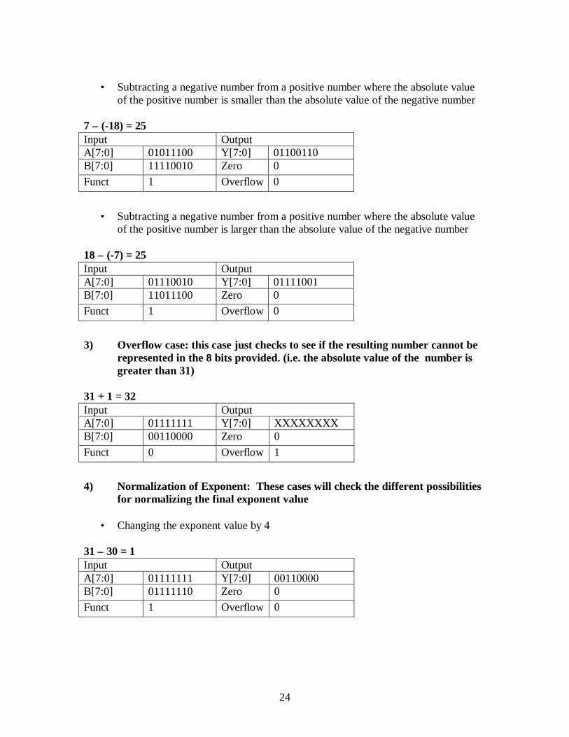
• Subtracting a negative number from a positive number where the absolute valueof the positive number is smaller than the absolute value of the negative number
7 – (-18) = 25
• Subtracting a negative number from a positive number where the absolute valueof the positive number is larger than the absolute value of the negative number
18 – (-7) = 25
3) Overflow case: this case just checks to see if the resulting number cannot berepresented in the 8 bits provided. (i.e. the absolute value of the number isgreater than 31)
31 + 1 = 32
4) Normalization of Exponent: These cases will check the different possibilitiesfor normalizing the final exponent value
• Changing the exponent value by 4
31 – 30 = 1
Input OutputA[7:0] 01011100 Y[7:0] 01100110B[7:0] 11110010 Zero 0Funct 1 Overflow 0
Input OutputA[7:0] 01110010 Y[7:0] 01111001B[7:0] 11011100 Zero 0Funct 1 Overflow 0
Input OutputA[7:0] 01111111 Y[7:0] XXXXXXXXB[7:0] 00110000 Zero 0Funct 0 Overflow 1
Input OutputA[7:0] 01111111 Y[7:0] 00110000B[7:0] 01111110 Zero 0Funct 1 Overflow 0
25
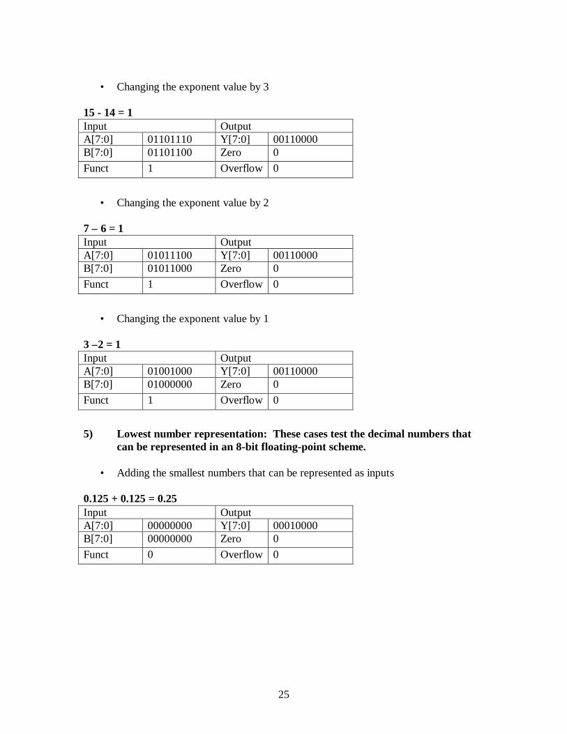
• Changing the exponent value by 3
15 - 14 = 1
• Changing the exponent value by 2
7 – 6 = 1
• Changing the exponent value by 1
3 –2 = 1
5) Lowest number representation: These cases test the decimal numbers thatcan be represented in an 8-bit floating-point scheme.
• Adding the smallest numbers that can be represented as inputs
0.125 + 0.125 = 0.25
Input OutputA[7:0] 01101110 Y[7:0] 00110000B[7:0] 01101100 Zero 0Funct 1 Overflow 0
Input OutputA[7:0] 01011100 Y[7:0] 00110000B[7:0] 01011000 Zero 0Funct 1 Overflow 0
Input OutputA[7:0] 01001000 Y[7:0] 00110000B[7:0] 01000000 Zero 0Funct 1 Overflow 0
Input OutputA[7:0] 00000000 Y[7:0] 00010000B[7:0] 00000000 Zero 0Funct 0 Overflow 0
26
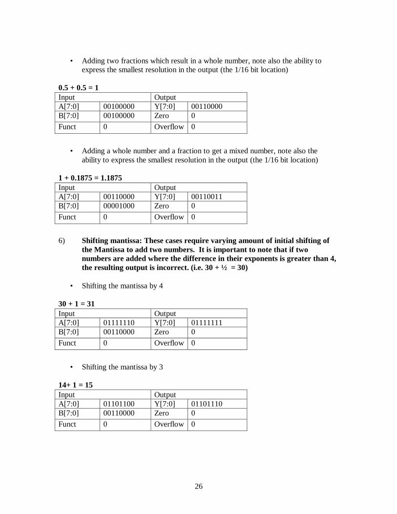
• Adding two fractions which result in a whole number, note also the ability toexpress the smallest resolution in the output (the 1/16 bit location)
0.5 + 0.5 = 1
• Adding a whole number and a fraction to get a mixed number, note also theability to express the smallest resolution in the output (the 1/16 bit location)
1 + 0.1875 = 1.1875
6) Shifting mantissa: These cases require varying amount of initial shifting ofthe Mantissa to add two numbers. It is important to note that if twonumbers are added where the difference in their exponents is greater than 4,the resulting output is incorrect. (i.e. 30 + ½ = 30)
• Shifting the mantissa by 4
30 + 1 = 31
• Shifting the mantissa by 3
14+ 1 = 15
Input OutputA[7:0] 00100000 Y[7:0] 00110000B[7:0] 00100000 Zero 0Funct 0 Overflow 0
Input OutputA[7:0] 00110000 Y[7:0] 00110011B[7:0] 00001000 Zero 0Funct 0 Overflow 0
Input OutputA[7:0] 01111110 Y[7:0] 01111111B[7:0] 00110000 Zero 0Funct 0 Overflow 0
Input OutputA[7:0] 01101100 Y[7:0] 01101110B[7:0] 00110000 Zero 0Funct 0 Overflow 0

27
• Shifting the mantissa by 2
6 + 1 = 7
• Shifting the mantissa by 1
2 + 1 = 3
Input OutputA[7:0] 01011000 Y[7:0] 01011100B[7:0] 00110000 Zero 0Funct 0 Overflow 0
Input OutputA[7:0] 01000000 Y[7:0] 01001000B[7:0] 00110000 Zero 0Funct 0 Overflow 0

28
Schematics and Verilog
In this section you will find versions of the same Verilog code. The first code is amore readable version. It still have module separations and busses which representvarious inputs. This is also the code with comments since it is easier to follow.
The second code is the version of code with all of the busses flatted so thatElectric can handle the synthesized module. The hierarchy of this code was laterremoved since the data analyzer outputs a hierarchical vhdl file which also cannot behandled in Electric.
Readable Verilog Code//This is not the code that was synthesized//Electric does not recognize busses so the code was redone with all of the// busses flattened
//Also, this code contains verilog code for both the exponent and mantissa datapaths
module topadder(A, B, funct, zero, Y);
input [7:0] A ; //Input number Ainput [7:0] B ; //Input number Binput funct ; // funct=0 is add, and funct=1 is subtract
output zero ; //the output at Y is not corrent for cases thatresult
//in zero so a seperate output pin is assigned//for zero cases// zero = 1 when result is zero, zero = 0 for//nonzero results
output [7:0] Y ; //answer
wire [2:0] exp_A; //internal wires for easier coding, representwire [2:0] exp_B; // theexponential values for A, B, and Ywire [2:0] exp_Y;
wire sign_Y; //sign bit of Y
wire [3:0] mant_Y; //mantissa bits of Y
wire [2:0] exp_diff_norm; //used in the normalization module, tells the module//what value to add or subtract to a temp exponent//value
29
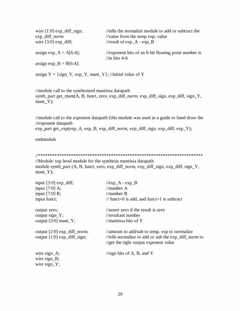
wire [1:0] exp_diff_sign; //tells the normalize module to add or subtract theexp_diff_norm //value from the temp exp. valuewire [3:0] exp_diff; //result of exp_A - exp_B
assign exp_A = A[6:4]; //exponent bits of an 8-bit floating point number is//in bits 4-6
assign exp_B = B[6:4];
assign Y = {sign_Y, exp_Y, mant_Y}; //initial value of Y
//module call to the synthesized mantissa datapathsynth_part get_mant(A, B, funct, zero, exp_diff_norm, exp_diff_sign, exp_diff, sign_Y,mant_Y);
//module call to the exponent datapath (this module was used as a guide to hand draw the//exponent datapathexp_part get_exp(exp_A, exp_B, exp_diff_norm, exp_diff_sign, exp_diff, exp_Y);
endmodule
//**********************************************************************//Module: top level module for the synthesis mantissa datapathmodule synth_part (A, B, funct, zero, exp_diff_norm, exp_diff_sign, exp_diff, sign_Y,mant_Y);
input [3:0] exp_diff; //exp_A - exp_Binput [7:0] A; //number Ainput [7:0] B; //number Binput funct; // funct=0 is add, and funct=1 is subtract
output zero; //assert zero if the result is zerooutput sign_Y; //resultant numberoutput [3:0] mant_Y; //mantissa bits of Y
output [2:0] exp_diff_norm; //amount to add/sub to temp. exp to normalizeoutput [1:0] exp_diff_sign; //tells normalize to add or sub the exp_diff_norm to
//get the right output exponent value
wire sign_A; //sign bits of A, B, and Ywire sign_B;wire sign_Y;
30
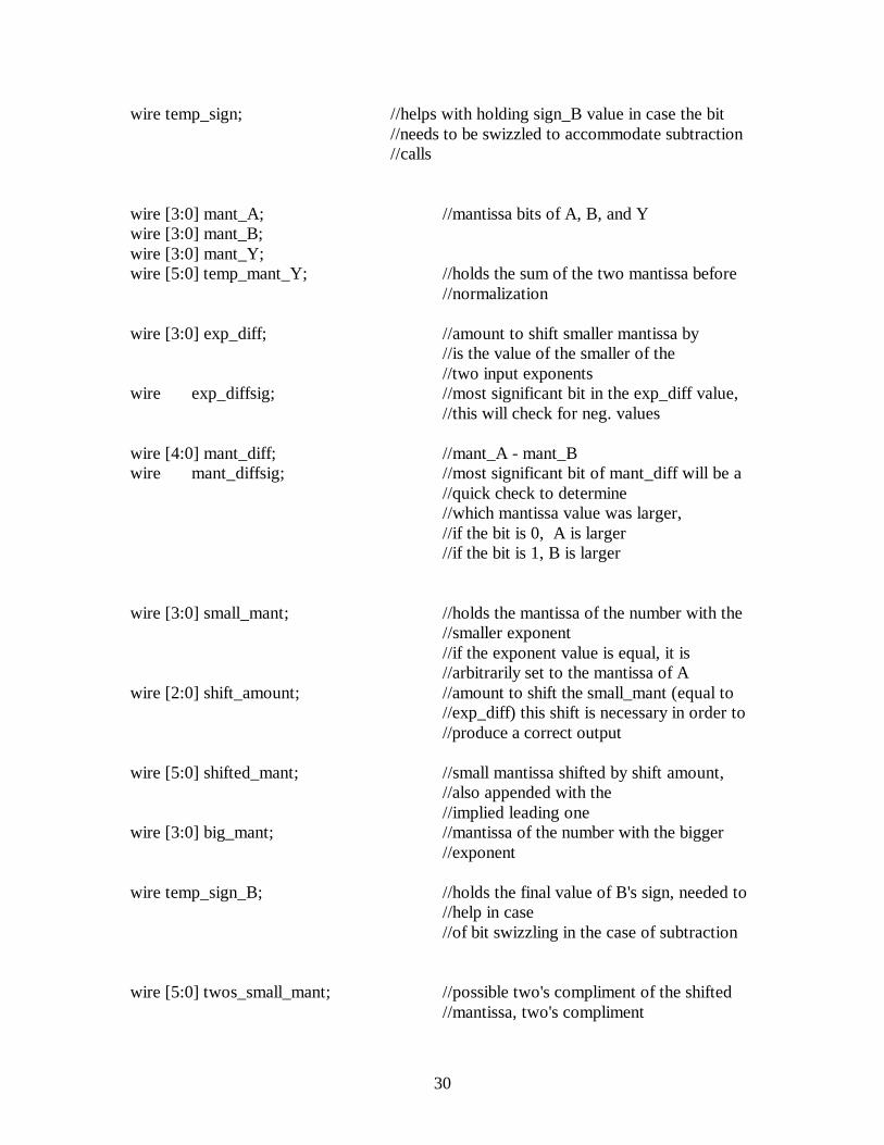
wire temp_sign; //helps with holding sign_B value in case the bit//needs to be swizzled to accommodate subtraction//calls
wire [3:0] mant_A; //mantissa bits of A, B, and Ywire [3:0] mant_B;wire [3:0] mant_Y;wire [5:0] temp_mant_Y; //holds the sum of the two mantissa before
//normalization
wire [3:0] exp_diff; //amount to shift smaller mantissa by//is the value of the smaller of the//two input exponents
wire exp_diffsig; //most significant bit in the exp_diff value,//this will check for neg. values
wire [4:0] mant_diff; //mant_A - mant_Bwire mant_diffsig; //most significant bit of mant_diff will be a
//quick check to determine//which mantissa value was larger,//if the bit is 0, A is larger//if the bit is 1, B is larger
wire [3:0] small_mant; //holds the mantissa of the number with the//smaller exponent//if the exponent value is equal, it is//arbitrarily set to the mantissa of A
wire [2:0] shift_amount; //amount to shift the small_mant (equal to//exp_diff) this shift is necessary in order to//produce a correct output
wire [5:0] shifted_mant; //small mantissa shifted by shift amount,//also appended with the//implied leading one
wire [3:0] big_mant; //mantissa of the number with the bigger//exponent
wire temp_sign_B; //holds the final value of B's sign, needed to//help in case//of bit swizzling in the case of subtraction
wire [5:0] twos_small_mant; //possible two's compliment of the shifted//mantissa, two's compliment
31
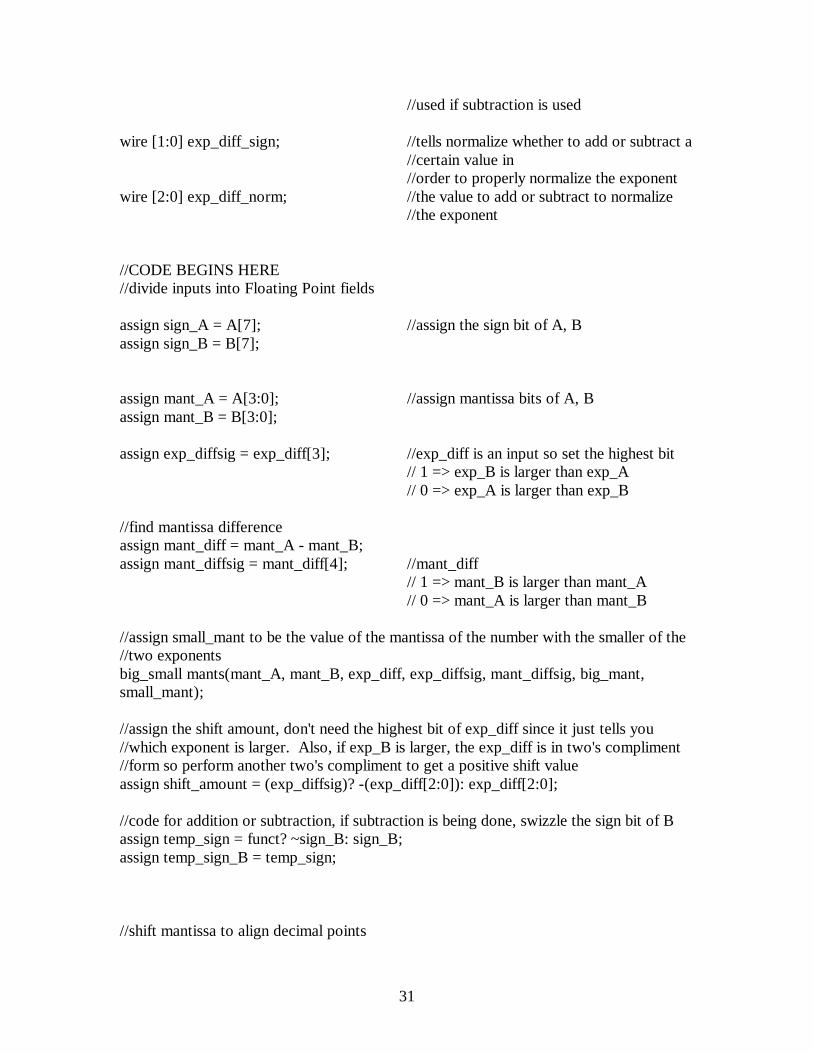
//used if subtraction is used
wire [1:0] exp_diff_sign; //tells normalize whether to add or subtract a//certain value in//order to properly normalize the exponent
wire [2:0] exp_diff_norm; //the value to add or subtract to normalize//the exponent
//CODE BEGINS HERE//divide inputs into Floating Point fields
assign sign_A = A[7]; //assign the sign bit of A, Bassign sign_B = B[7];
assign mant_A = A[3:0]; //assign mantissa bits of A, Bassign mant_B = B[3:0];
assign exp_diffsig = exp_diff[3]; //exp_diff is an input so set the highest bit// 1 => exp_B is larger than exp_A// 0 => exp_A is larger than exp_B
//find mantissa differenceassign mant_diff = mant_A - mant_B;assign mant_diffsig = mant_diff[4]; //mant_diff
// 1 => mant_B is larger than mant_A// 0 => mant_A is larger than mant_B
//assign small_mant to be the value of the mantissa of the number with the smaller of the//two exponentsbig_small mants(mant_A, mant_B, exp_diff, exp_diffsig, mant_diffsig, big_mant,small_mant);
//assign the shift amount, don't need the highest bit of exp_diff since it just tells you//which exponent is larger. Also, if exp_B is larger, the exp_diff is in two's compliment//form so perform another two's compliment to get a positive shift valueassign shift_amount = (exp_diffsig)? -(exp_diff[2:0]): exp_diff[2:0];
//code for addition or subtraction, if subtraction is being done, swizzle the sign bit of Bassign temp_sign = funct? ~sign_B: sign_B;assign temp_sign_B = temp_sign;
//shift mantissa to align decimal points

32
right_shifter shift_mantissa(small_mant, shift_amount, shifted_mant);
//calculate the two's compliment of the shifted mant, only needed in the case of//subtraction or equivalent case (i.e. adding a negative number to a positive number)twos_comp two_small_mant(sign_A, sign_B, funct, shifted_mant, twos_small_mant);
//add the two mantissas togetherassign temp_mant_Y ={1'b1, big_mant} + twos_small_mant;
//assign zero detectzero_detect zero_find(sign_A, sign_B, funct, exp_diff, mant_diff, zero);
//normalize the mantissa and exponent value so it's back in floating point representationnormalize normal(temp_mant_Y, mant_Y, exp_diff_norm, exp_diff_sign);
//determine sign of the final valuefinal_sign sign_find(exp_diffsig, mant_diffsig, exp_diff, sign_A, temp_sign_B, sign_Y);
endmodule
//**********************************************************************//Module: see if the result of the operation results in a zero
module zero_detect (sign_A, sign_B, funct, exp_diff, mant_diff, zero);input sign_A, sign_B, funct; //sign bits of A and B, and function being
//performedinput [3:0] exp_diff; //exponential difference (exp_A - exp_B)input [4:0] mant_diff; //mantissa difference (mant_A - mant_B)output zero; //assert true when result is zero
reg zero;
always@(sign_A or sign_B or funct or exp_diff or mant_diff)
//(sign_A^sign_B)^funct is 1 when after you convert the operation to addition//(i.e. a - b => a + (-b) OR a - (-b) => a + b) if the signs of A and B are different
if(((sign_A^sign_B)^funct)&(exp_diff == 4'b0000)&(mant_diff == 5'b00000))zero <= 1; //zero asserted if the signs of A and B are
//different and there is no//difference in the mantissa and exponent

33
// a number plus a conjugateelse
zero <= 0;
endmodule
//**********************************************************************//Module: perform two's compliment if subtraction operation is called for
module twos_comp (sign_A, sign_B, funct, shifted_mant, twos_small_mant);input sign_A, sign_B, funct; //sign bits of A and B, function being
//performedinput [5:0] shifted_mant; //the smaller mantissa shifted so that the
//numbers are aligned in order to do the//operation
output [5:0] twos_small_mant; //result either same as input or the two's//compliment of input
//two's compliment of shifted mantissa if numbers are being subtracted or adding//a negative numberassign twos_small_mant = ((sign_A^sign_B)^funct)? -(shifted_mant): shifted_mant;
endmodule
//**********************************************************************//Module: Normalize the final exponent and mantissa value so it can be represented in//floating point format
module normalize (in_mant, out_mant, exp_diff_norm, exp_diff_sign);
input [5:0] in_mant; //input sign_A, sign_B, funct;
output [3:0] out_mant; //normalized mantissa valueoutput [1:0]exp_diff_sign; //tells the exponent nomalization module
//whether the exponent value//needs a value added or subtracted in order//to be normalized, this is a 2 bit bus because//it simplifies the exponent datapath layout
output [2:0]exp_diff_norm; //the value that needs to be added or//subtracted
reg [5:0] in_mant;reg [3:0] out_mant;reg [2:0]exp_diff_sign;

34
reg [2:0]exp_diff_norm;
//find the first "1" (i.e. locate a one and shift accordingly in order to get the implicite//leading one for floating point representationalways@(in_mant)begin
if (in_mant[5])begin
out_mant <= in_mant[4:1];exp_diff_norm <= 3'b001;exp_diff_sign <= 2'b01; //0 means add to in_exp
//the value in exp_diff_sign[1] can//be decoded to determine the//operation// 0 => add// 1 => subtract//the other bit is used in the exponent//datapath for the select_bar line of a//mux
endelse if (in_mant[4])
beginout_mant <= in_mant[3:0];exp_diff_norm <= 3'b000;exp_diff_sign <=2'b01;
endelse if (in_mant[3])
begin out_mant <= {in_mant[2:0], 1'b0}; exp_diff_norm <= 3'b001; //1 exp_diff_sign <= 2'b10; // 1 means to subtract
endelse if (in_mant[2])
begin out_mant <= {in_mant[1:0], 2'b00}; exp_diff_norm <= 3'b010; //2 exp_diff_sign <= 2'b10; //subtract
endelse if (in_mant[1])
begin out_mant <= {in_mant[0], 3'b000}; exp_diff_norm <= 3'b011; //3 exp_diff_sign <= 2'b10; //subtract
endelse if (in_mant[0])

35
begin out_mant <= 4'b0000; exp_diff_norm <= 3'b100; //4 exp_diff_sign <= 2'b10; //subtract
end else begin out_mant <= in_mant; exp_diff_norm <= 3'b001; //1 exp_diff_sign <= 2'b01; //add endend
endmodule
//**********************************************************************//Module: Determines the sign of the resulting valuemodule final_sign (exp_diffsig, mant_diffsig, exp_diff, sign_A, sign_B, sign_Y);
input exp_diffsig; // 0 => exp_A is greater than or equal to//exp_B// 1 => exp_A is less than exp_B
input mant_diffsig; // 0 => mant_A is greater than or equal to//mant_B// 1 => mant_A is less than mant_B
input [3:0]exp_diff; //the exponent difference (exp_A - exp_B)input sign_A; //sign bits of A, B, and Yinput sign_B;output sign_Y;
reg sign_Y;
always@(exp_diffsig or mant_diffsig or exp_diff or sign_B or sign_A)begin
if (exp_diffsig)sign_Y <= sign_B; //if the exp_diffsig is 1 (number B is bigger)
//give sign_Y the sign of Belse begin
if (exp_diff == 4'b0000) //if the exp_diff is 0 (the two exp are//equal), check the mantissa values
beginif (mant_diffsig) //if the mant_diffsig is 1 (number B is
//bigger) sign_Y <=sign_B; //give sign_Y the sign //of Belse

36
sign_Y <= sign_A; //if the exp_diff is 0 and the//mant_diffsig != 1
end //A and B have the same exponent but the//difference in the mantissas are zero or//greater
else sign_Y <= sign_A; //give sign_Y the sign of Aend //give sign_Y the sign of A
//if exp_diffsig != 1//(exp_A is bigger) and exp_diff is greater//than zero
end
endmodule
//**********************************************************************//Module: find which mantissa is biggermodule big_small (mant_A, mant_B, exp_diff, exp_diffsig, mant_diffsig, big_mant,small_mant);
input [3:0]mant_A, mant_B, exp_diff; //mantissa bits of A, B and the difference in ///the exponents (exp_A -exp_B)
input exp_diffsig, mant_diffsig; //bits which tell which mantissa and//exponent value was larger for exp_diffsig// 0 => exp_A is greater than or equal to//exp_B// 1 => exp_A is less than exp_B//for mant_diffsig// 0 => mant_A is greater than or equal to//mant_B// 1 => mant_A is less than mant_B
output [3:0] big_mant, small_mant; //the larger exponant's mantissa//and the smaller exponent's mantissa
reg [3:0]mant_A, mant_B, exp_diff;reg exp_diffsig;reg [3:0] big_mant, small_mant;
always@(mant_A or mant_B or exp_diff or exp_diffsig or mant_diffsig)
//if there exponents are equalif (exp_diff == 4'b0000)
beginbig_mant <= (mant_diffsig)? mant_B: mant_A;
//assign based on which mantissa value is larger

37
small_mant <= (mant_diffsig)? mant_A: mant_B;end
//if the exponents are not equalelse
beginbig_mant <= (exp_diffsig)? mant_B: mant_A;
//big mant is the mantissa of the number with the larger exponentsmall_mant <= (exp_diffsig)? mant_A: mant_B;
end//small mant is the other mantissa
endmodule
//**********************************************************************//Module: Shifts a given numner to the right by an amount (shift_amt)module right_shifter(small_mant, shift_amt, shifted_mant);
input [3:0] small_mant; //the smaller exponent's mantissainput [2:0] shift_amt; //the amount to right shiftoutput [5:0] shifted_mant; //resulted shifted mantissa
reg [3:0] small_mant;reg [5:0] shifted_mant;
//shift and append the implicite leading onealways@(small_mant or shift_amt)
case (shift_amt)3'b000: shifted_mant <= {2'b01, small_mant[3:0]};3'b001: shifted_mant <= {3'b001, small_mant[3:1]};3'b010: shifted_mant <= {4'b0001, small_mant[3:2]};3'b011: shifted_mant <= {5'b00001, small_mant[3]};3'b100: shifted_mant <= 6'b000001;
default: shifted_mant <= 6'b000000;
endcase
endmodule
//**********************************************************************//Module: Verilog representation of the exponent datapath

38
module exp_part(exp_A, exp_B, exp_diff_norm, exp_diff_sign, exp_diff, exp_Y);
input [2:0] exp_A, exp_B, exp_diff_norm; //exponent values of A, B and the//normalization number
input [1:0]exp_diff_sign; //operation in order to normalize
output [3:0] exp_diff; //the difference between exp_A - exp_Boutput [2:0] exp_Y; //final exponent value
wire exp_diffsig; //0 => exp_A is greater than or equal to//exp_B// 1 => exp_A is less than exp_B
wire [2:0] temp_exp_Y; //holds the larger exponent value
reg [2:0] exp_Y;
//find exponent difference
assign exp_diff = exp_A – exp_B; //find the exponent differenceassign exp_diffsig = exp_diff[3];
//give temp_exp_Y the exp value of the bigger exp valueassign temp_exp_Y = (exp_diffsig)? exp_B: exp_A;
//normalizing the exponent valuealways@(exp_diff_norm or exp_diff_sign or temp_exp_Y)
if(exp_diff_sign[1]) //if =1 subtractexp_Y <= (temp_exp_Y) - (exp_diff_norm);
else//if =0 add
exp_Y <= (temp_exp_Y) + (exp_diff_norm);
endmodule

39
Flatten Code//Same code but with flattened busses for Electric//Not as many comments since it's already hard to read
module topadder(A7, A6, A5, A4, A3, A2, A1, A0, B7, B6, B5, B4, B3, B2, B1, B0,funct, zero, Y7, Y6, Y5, Y4, Y3, Y2, Y1, Y0);
input funct; // funct=0 is add, and funct=1 is subtract
input A0;input A1;input A2;input A3;input A4;input A5;input A6;input A7;
input B0;input B1;input B2;input B3;input B4;input B5;input B6;input B7;
output zero ;output Y0;output Y1;output Y2;output Y3;output Y4;output Y5;output Y6;output Y7;
wire sign_Y;
wire exp_diff_norm0;wire exp_diff_norm1;wire exp_diff_norm2;
wire exp_diff_sign0;wire exp_diff_sign1;
40
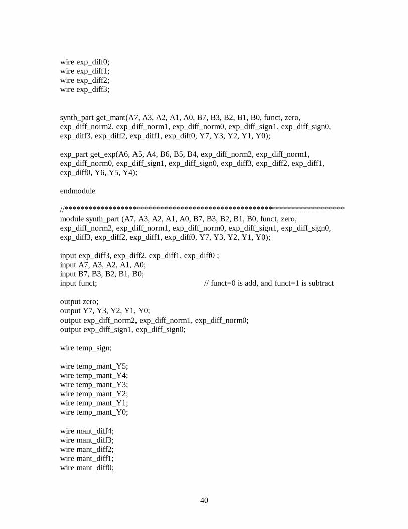
wire exp_diff0;wire exp_diff1;wire exp_diff2;wire exp_diff3;
synth_part get_mant(A7, A3, A2, A1, A0, B7, B3, B2, B1, B0, funct, zero,exp_diff_norm2, exp_diff_norm1, exp_diff_norm0, exp_diff_sign1, exp_diff_sign0,exp_diff3, exp_diff2, exp_diff1, exp_diff0, Y7, Y3, Y2, Y1, Y0);
exp_part get_exp(A6, A5, A4, B6, B5, B4, exp_diff_norm2, exp_diff_norm1,exp_diff_norm0, exp_diff_sign1, exp_diff_sign0, exp_diff3, exp_diff2, exp_diff1,exp_diff0, Y6, Y5, Y4);
endmodule
//**********************************************************************module synth_part (A7, A3, A2, A1, A0, B7, B3, B2, B1, B0, funct, zero,exp_diff_norm2, exp_diff_norm1, exp_diff_norm0, exp_diff_sign1, exp_diff_sign0,exp_diff3, exp_diff2, exp_diff1, exp_diff0, Y7, Y3, Y2, Y1, Y0);
input exp_diff3, exp_diff2, exp_diff1, exp_diff0 ;input A7, A3, A2, A1, A0;input B7, B3, B2, B1, B0;input funct; // funct=0 is add, and funct=1 is subtract
output zero;output Y7, Y3, Y2, Y1, Y0;output exp_diff_norm2, exp_diff_norm1, exp_diff_norm0;output exp_diff_sign1, exp_diff_sign0;
wire temp_sign;
wire temp_mant_Y5;wire temp_mant_Y4;wire temp_mant_Y3;wire temp_mant_Y2;wire temp_mant_Y1;wire temp_mant_Y0;
wire mant_diff4;wire mant_diff3;wire mant_diff2;wire mant_diff1;wire mant_diff0;
41
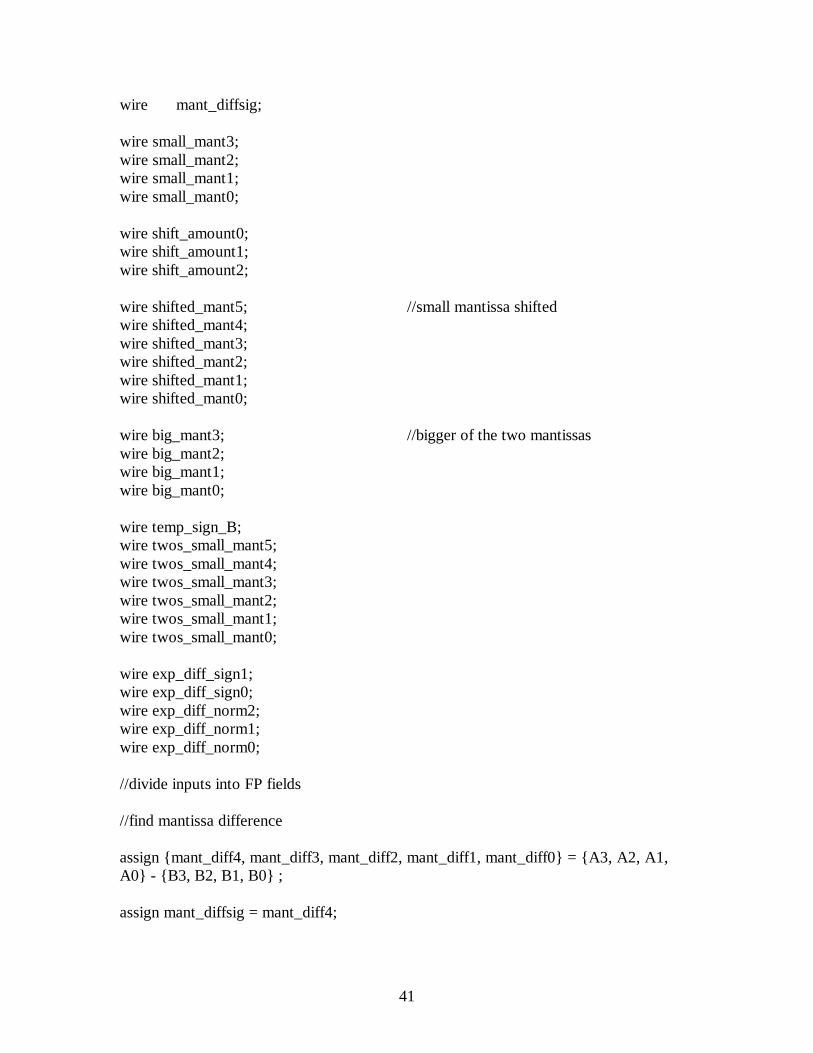
wire mant_diffsig;
wire small_mant3;wire small_mant2;wire small_mant1;wire small_mant0;
wire shift_amount0;wire shift_amount1;wire shift_amount2;
wire shifted_mant5; //small mantissa shiftedwire shifted_mant4;wire shifted_mant3;wire shifted_mant2;wire shifted_mant1;wire shifted_mant0;
wire big_mant3; //bigger of the two mantissaswire big_mant2;wire big_mant1;wire big_mant0;
wire temp_sign_B;wire twos_small_mant5;wire twos_small_mant4;wire twos_small_mant3;wire twos_small_mant2;wire twos_small_mant1;wire twos_small_mant0;
wire exp_diff_sign1;wire exp_diff_sign0;wire exp_diff_norm2;wire exp_diff_norm1;wire exp_diff_norm0;
//divide inputs into FP fields
//find mantissa difference
assign {mant_diff4, mant_diff3, mant_diff2, mant_diff1, mant_diff0} = {A3, A2, A1,A0} - {B3, B2, B1, B0} ;
assign mant_diffsig = mant_diff4;
42
//assign small_mant to be the value of the mantissa of the number with the smaller of the//two exponentsbig_small mants(A3, A2, A1, A0, B3, B2, B1, B0, exp_diff3, exp_diff2, exp_diff1,exp_diff0, mant_diffsig, big_mant3, big_mant2, big_mant1, big_mant0, small_mant3,small_mant2, small_mant1, small_mant0);
assign {shift_amount2, shift_amount1, shift_amount0} = (exp_diff3)? -({exp_diff2,exp_diff1, exp_diff0}): {exp_diff2, exp_diff1, exp_diff0};
//code for addition or subtraction
assign temp_sign = funct? ~B7: B7;assign temp_sign_B = temp_sign;
//shift mantissa to align decimal pointsright_shifter shift_mantissa(small_mant3, small_mant2, small_mant1, small_mant0,shift_amount2, shift_amount1, shift_amount0, shifted_mant5, shifted_mant4,shifted_mant3, shifted_mant2, shifted_mant1, shifted_mant0);
twos_comp two_small_mant(A7, B7, funct, shifted_mant5, shifted_mant4,shifted_mant3, shifted_mant2, shifted_mant1, shifted_mant0, twos_small_mant5,twos_small_mant4, twos_small_mant3, twos_small_mant2, twos_small_mant1,twos_small_mant0);
//add the two mantissas together
assign {temp_mant_Y5, temp_mant_Y4, temp_mant_Y3, temp_mant_Y2,temp_mant_Y1, temp_mant_Y0} =
{1'b1, {big_mant3, big_mant2, big_mant1, big_mant0}} +{twos_small_mant5, twos_small_mant4, twos_small_mant3, twos_small_mant2,twos_small_mant1, twos_small_mant0};
//assign zero detectzero_detect zero_find(A7, B7, funct, exp_diff3, exp_diff2, exp_diff1, exp_diff0,
mant_diff4, mant_diff3, mant_diff2, mant_diff1, mant_diff0, zero);
normalize normal(temp_mant_Y5, temp_mant_Y4, temp_mant_Y3, temp_mant_Y2,temp_mant_Y1, temp_mant_Y0, Y3, Y2, Y1, Y0, exp_diff_norm2, exp_diff_norm1,exp_diff_norm0, exp_diff_sign1, exp_diff_sign0);
final_sign sign_find(mant_diffsig, exp_diff3, exp_diff2, exp_diff1, exp_diff0, A7,temp_sign_B, Y7);
endmodule

43
//**********************************************************************
module zero_detect (A7, B7, funct, exp_diff3, exp_diff2, exp_diff1, exp_diff0,mant_diff4, mant_diff3, mant_diff2, mant_diff1, mant_diff0, zero);input A7, B7, funct;
input exp_diff3, exp_diff2, exp_diff1, exp_diff0;input mant_diff4, mant_diff3, mant_diff2, mant_diff1, mant_diff0;
output zero;reg zero;
always@(A7 or B7 or funct or exp_diff3 or exp_diff2 or exp_diff1 or exp_diff0 ormant_diff4 or mant_diff3 or
mant_diff2 or mant_diff1 or mant_diff0)if(((A7^B7)^funct)&({exp_diff3, exp_diff2, exp_diff1, exp_diff0} == 4'b0000) &
({mant_diff4, mant_diff3, mant_diff2, mant_diff1, mant_diff0} == 5'b00000))zero <= 1;
elsezero <= 0;
endmodule
//**********************************************************************module twos_comp (A7, B7, funct, shifted_mant5, shifted_mant4, shifted_mant3,shifted_mant2, shifted_mant1, shifted_mant0, twos_small_mant5, twos_small_mant4,twos_small_mant3, twos_small_mant2, twos_small_mant1, twos_small_mant0);
input A7, B7, funct;input shifted_mant5, shifted_mant4, shifted_mant3, shifted_mant2, shifted_mant1,
shifted_mant0;
output twos_small_mant5, twos_small_mant4, twos_small_mant3, twos_small_mant2,twos_small_mant1, twos_small_mant0;
//two's compliment of shifted mantissa if numbers are being subtracted or adding//a negative number
assign {twos_small_mant5, twos_small_mant4, twos_small_mant3, twos_small_mant2,twos_small_mant1, twos_small_mant0} =
((A7^B7)^funct)? -({shifted_mant5, shifted_mant4, shifted_mant3,shifted_mant2, shifted_mant1, shifted_mant0}):
{shifted_mant5, shifted_mant4, shifted_mant3, shifted_mant2, shifted_mant1,shifted_mant0};

44
endmodule
//**********************************************************************module normalize (in_mant5, in_mant4, in_mant3, in_mant2, in_mant1, in_mant0,
out_mant3, out_mant2, out_mant1, out_mant0, exp_diff_norm2,exp_diff_norm1, exp_diff_norm0, exp_diff_sign1, exp_diff_sign0);
input in_mant5, in_mant4, in_mant3, in_mant2, in_mant1, in_mant0;
output out_mant3, out_mant2, out_mant1, out_mant0;output exp_diff_sign1, exp_diff_sign0;output exp_diff_norm2, exp_diff_norm1, exp_diff_norm0;
reg in_mant5, in_mant4, in_mant3, in_mant2, in_mant1, in_mant0;reg out_mant3, out_mant2, out_mant1, out_mant0;reg exp_diff_sign1, exp_diff_sign0;reg exp_diff_norm2, exp_diff_norm1, exp_diff_norm0;
always@(in_mant5 or in_mant4 or in_mant3 or in_mant2 or in_mant1 or in_mant0)begin
if (in_mant5)begin
{out_mant3, out_mant2, out_mant1, out_mant0} <= {in_mant4,in_mant3, in_mant2, in_mant1};{exp_diff_norm2, exp_diff_norm1, exp_diff_norm0} <= 3'b001;{exp_diff_sign1, exp_diff_sign0} <= 2'b01;
endelse if (in_mant4)
begin{out_mant3, out_mant2, out_mant1, out_mant0} <= {in_mant3,in_mant2, in_mant1, in_mant0};{exp_diff_norm2, exp_diff_norm1, exp_diff_norm0} <= 3'b000;{exp_diff_sign1, exp_diff_sign0} <=2'b01;
endelse if (in_mant3)
begin {out_mant3, out_mant2, out_mant1, out_mant0} <={{in_mant2, in_mant1, in_mant0}, 1'b0};
{exp_diff_norm2, exp_diff_norm1, exp_diff_norm0} <= 3'b001; {exp_diff_sign1, exp_diff_sign0} <= 2'b10;
endelse if (in_mant2)
begin{out_mant3, out_mant2, out_mant1, out_mant0} <= {{in_mant1,in_mant0}, 2'b00};
45
{exp_diff_norm2, exp_diff_norm1, exp_diff_norm0} <= 3'b010; {exp_diff_sign1, exp_diff_sign0} <= 2'b10;
endelse if (in_mant1)
begin{out_mant3, out_mant2, out_mant1, out_mant0} <= {in_mant0,3'b000};
{exp_diff_norm2, exp_diff_norm1, exp_diff_norm0} <= 3'b011; {exp_diff_sign1, exp_diff_sign0} <= 2'b10;
endelse if (in_mant0)
begin {out_mant3, out_mant2, out_mant1, out_mant0} <= 4'b0000; {exp_diff_norm2, exp_diff_norm1, exp_diff_norm0} <= 3'b100; {exp_diff_sign1, exp_diff_sign0} <= 2'b10;
end else begin {out_mant3, out_mant2, out_mant1, out_mant0} <= {in_mant3,
in_mant2, in_mant1, in_mant0}; {exp_diff_norm2, exp_diff_norm1, exp_diff_norm0} <= 3'b001; {exp_diff_sign1, exp_diff_sign0} <= 2'b01; endend
endmodule
//**********************************************************************module final_sign (mant_diffsig, exp_diff3, exp_diff2, exp_diff1, exp_diff0, sign_A,sign_B, sign_Y);
input mant_diffsig;input exp_diff3, exp_diff2, exp_diff1, exp_diff0;input sign_A;input sign_B;
output sign_Y;
reg sign_Y;
always@(mant_diffsig or exp_diff3 or exp_diff2 or exp_diff1 or exp_diff0 or sign_B orsign_A)begin
if (exp_diff3)sign_Y <= sign_B; //if the exp_diffsig is 1 (number B is bigger)
//give sign_Y the sign of B
46
elsebegin
if ({exp_diff3, exp_diff2, exp_diff1, exp_diff0} == 4'b0000)//if the exp_diff is 0 (the two exp are equal),
begin //check the mantissa values if (mant_diffsig) //if the mant_diffsig is 1 (B is bigger)
sign_Y <=sign_B; //give sign_Y the sign//of B
elsesign_Y <= sign_A; //if the exp_diff is 0
//and the mant_diffsig//!= 1
end //(A and B have the//same exponent but//the difference in the//mantissas are zero or//greater
else sign_Y <= sign_A;//give sign_Y the sign of A
end //give sign_Y the sign of A if exp_diffsig !=//1 (exp_A is bigger)//and exp_diff is greater than zero
end
endmodule
//**********************************************************************//find which mantissa is bigger
module big_small (A3, A2, A1, A0, B3, B2, B1, B0, exp_diff3, exp_diff2, exp_diff1,exp_diff0, mant_diffsig, big_mant3, big_mant2, big_mant1, big_mant0, small_mant3,small_mant2, small_mant1, small_mant0);
input A3, A2, A1, A0;input B3, B2, B1, B0;input exp_diff3, exp_diff2, exp_diff1, exp_diff0;input mant_diffsig;
output big_mant3, big_mant2, big_mant1, big_mant0;output small_mant3, small_mant2, small_mant1, small_mant0;
reg A3, A2, A1, A0, B3, B2, B1, B0, exp_diff3, exp_diff2, exp_diff1, exp_diff0;reg big_mant3, big_mant2, big_mant1, big_mant0, small_mant3, small_mant2,small_mant1, small_mant0;

47
always@(A3 or A2 or A1 or A0 or B3 or B2 or B1 or B0 or exp_diff3 or exp_diff2 orexp_diff1
or exp_diff0 or mant_diffsig)
if ({exp_diff3, exp_diff2, exp_diff1, exp_diff0} == 4'b0000)begin
{big_mant3, big_mant2, big_mant1, big_mant0} <=(mant_diffsig)? {B3, B2, B1, B0}: {A3, A2, A1, A0};{small_mant3, small_mant2, small_mant1, small_mant0} <=(mant_diffsig)? {A3, A2, A1, A0}: {B3, B2, B1, B0};
endelse
begin{big_mant3, big_mant2, big_mant1, big_mant0} <= (exp_diff3)?{B3, B2, B1, B0}: {A3, A2, A1, A0};{small_mant3, small_mant2, small_mant1, small_mant0} <=(exp_diff3)? {A3, A2, A1, A0}: {B3, B2, B1, B0};
end
endmodule
//**********************************************************************module right_shifter(small_mant3, small_mant2, small_mant1, small_mant0,shift_amount2, shift_amount1, shift_amount0, shifted_mant5, shifted_mant4,shifted_mant3, shifted_mant2, shifted_mant1, shifted_mant0);
input small_mant3, small_mant2, small_mant1, small_mant0;input shift_amount2, shift_amount1, shift_amount0;
output shifted_mant5, shifted_mant4, shifted_mant3, shifted_mant2, shifted_mant1,shifted_mant0;
reg small_mant3, small_mant2, small_mant1, small_mant0;reg shifted_mant5, shifted_mant4, shifted_mant3, shifted_mant2, shifted_mant1,shifted_mant0;
always@(small_mant3 or small_mant2 or small_mant1 or small_mant0 or shift_amount2or shift_amount1 or shift_amount0)
case ({shift_amount2, shift_amount1, shift_amount0})3'b000: {shifted_mant5, shifted_mant4, shifted_mant3,
shifted_mant2, shifted_mant1, shifted_mant0} <={2'b01, {small_mant3, small_mant2, small_mant1,small_mant0}};

48
3'b001: {shifted_mant5, shifted_mant4, shifted_mant3,shifted_mant2, shifted_mant1, shifted_mant0} <={3'b001, {small_mant3, small_mant2, small_mant1}};
3'b010: {shifted_mant5, shifted_mant4, shifted_mant3,shifted_mant2, shifted_mant1, shifted_mant0} <={4'b0001, {small_mant3, small_mant2}};
3'b011: {shifted_mant5, shifted_mant4, shifted_mant3,shifted_mant2, shifted_mant1, shifted_mant0} <={5'b00001, small_mant3};
3'b100: {shifted_mant5, shifted_mant4, shifted_mant3,shifted_mant2, shifted_mant1, shifted_mant0} <=6'b000001;
default: {shifted_mant5, shifted_mant4, shifted_mant3,shifted_mant2, shifted_mant1, shifted_mant0} <=6'b000000;
endcase
endmodule
//**********************************************************************//exponent stuffmodule exp_part(A6, A5, A4, B6, B5, B4, exp_diff_norm2, exp_diff_norm1,exp_diff_norm0, exp_diff_sign1, exp_diff_sign0, exp_diff3, exp_diff2, exp_diff1,exp_diff0, Y6, Y5, Y4);
input A6, A5, A4, B6, B5, B4, exp_diff_norm2, exp_diff_norm1, exp_diff_norm0;input exp_diff_sign1, exp_diff_sign0;
output exp_diff3, exp_diff2, exp_diff1, exp_diff0;output Y6, Y5, Y4;
wire exp_diffsig;wire temp_exp_Y2;wire temp_exp_Y1;wire temp_exp_Y0;
reg Y6, Y5, Y4;

49
//find exponent difference
assign {exp_diff3, exp_diff2, exp_diff1, exp_diff0} = {A6, A5, A4} - {B6, B5, B4};
//give the exp_Y the exp value of the bigger exp valueassign {temp_exp_Y2, temp_exp_Y1, temp_exp_Y0} = (exp_diff3)? {B6, B5, B4}: {A6,A5, A4};
always@(exp_diff_norm2 or exp_diff_norm1 or exp_diff_norm0 or exp_diff_sign1 orexp_diff_sign0 or
temp_exp_Y2 or temp_exp_Y1 or temp_exp_Y0)
if(exp_diff_sign1) //if =1 subtract{Y6, Y5, Y4} <= ({temp_exp_Y2, temp_exp_Y1, temp_exp_Y0}) -
({exp_diff_norm2, exp_diff_norm1, exp_diff_norm0});
else//if =0 add
{Y6, Y5, Y4} <= ({temp_exp_Y2, temp_exp_Y1, temp_exp_Y0}) +({exp_diff_norm2, exp_diff_norm1, exp_diff_norm0});
endmodule

50
SchematicsLeaf Cell: Mux2 Schematic
Leaf Cell: Full Adder Schematic
51
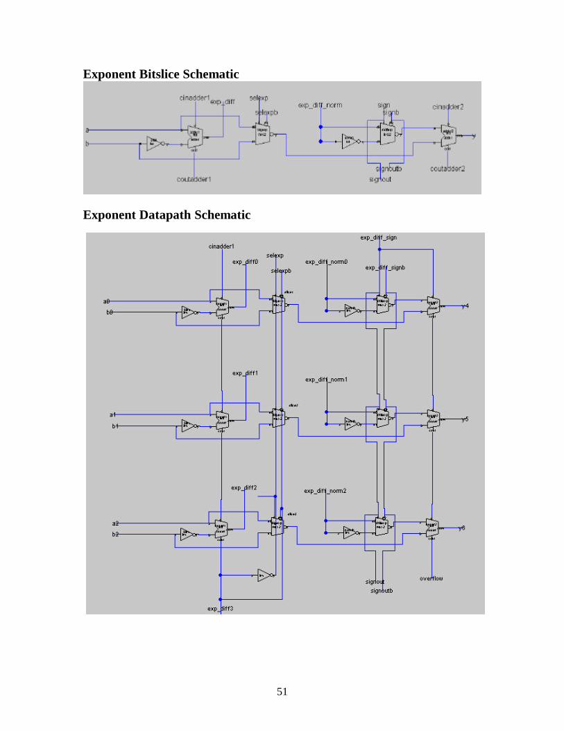
Exponent Bitslice Schematic
Exponent Datapath Schematic

52
Exponent and Mantissa Datapath Schematic
You will note that the schematic for the mantissa is missing. A program calleddata analyzer is supposed to be able to generate a schematic and layout from Verilogcode. However, the code cannot contain any hierarchy or busses for data lines. Theentire Verilog code was rewritten to accommodate Electric. However, even though theVerilog code does not contain any module calls, it implies an adder and a subtractor. TheData Analyzer program created an adder and a subtractor in submodules. The DataAnaylzer has a “Flatten Hierarchy” option, however, when we applied it to the design itsaid that the operation to flatten hierarchy was too expensive. The Data Analyzer createsa .vhdl file which is supposed to be imported into the Silicon Compiler option in Electric.Electric then reads the .vhdl netlist to create a layout and a schematic of your code. Onthe off chance that Electric would be able to handle the adder and subtractor submodules,we imported the Data Analyzer result to Electric. However, Electric was unable to createthe desired designs since it was unable to handle the .vhdl file sent by the Data Analyzer.There is a slight possibility that one could trick the Data Analyzer into creating the adderwithout generating a submodule. This would require someone to layout the result of eachbit on an adder using logic gates. This problem quickly turns into a gigantic undertaking.

53
LayoutLeaf Cell: Mux2
Leaf Cell: Full Adder Layout
54
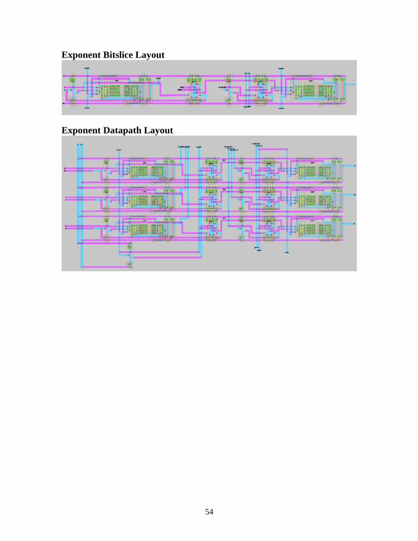
Exponent Bitslice Layout
Exponent Datapath Layout