7tmodgprs - igss.com
TRANSCRIPT

7-Technologies 7-Technologies A/S • Bistruphave 3 • DK-3460 Birkerød • Denmark
Phone: +45 45 900 700 • Fax: +45 45 900 701 • CVR no. DK 73 63 41 13 [email protected] • www.7T.dk
7TMODGPRS
IGSS Modicon Modbus GPRS Driver
User’s Manual

DISCLAIMER : This is an unpublished work, the copyright of which vests in SEVEN TECHNOLOGIES A/S.
All rights reserved. The information contained herein is the property of SEVEN TECHNOLOGIES and is supplied without liability for errors or omissions. No part may be reproduced or used except as authorised by contract or other written permission. The copyright and the foregoing restriction on reproduction and use extend to all media in which the information may be embodied.

7TMODGPRS IGSS Modicon Modbus GPRS driver
2
CONTENTS: 1 INTRODUCTION ................................................................................................................. 3
1.1 Software Requirements .......................................................................................... 3 1.2 Hardware Requirements ........................................................................................ 3
2 INSTALLATION ................................................................................................................... 4 2.1 Automatic Installation ............................................................................................. 4 2.2 Manual Installation ................................................................................................. 4
3 CONFIGURING THE DRIVER ............................................................................................ 6 3.1 Configuring the Objects ........................................................................................ 10
4 USE WITH GPRS NETWORKS ....................................................................................... 11 5 PERFORMANCE AND THROUGHPUT ........................................................................... 23 6 ERROR CODES ............................................................................................................... 24

7TMODGPRS IGSS Modicon Modbus GPRS driver
3
1 INTRODUCTION
This document describes how to set up and troubleshoot the IGSS 7TMODGPRS Interface Driver. The driver implements the Modicon Modbus protocol stack over GPRS.
1.1 SOFTWARE REQUIREMENTS
None (see Hardware Requirements below). The driver is designed to be used with IGSS version 7.0 and higher.
1.2 HARDWARE REQUIREMENTS
The driver requires a standard GPRS modem for the IGSS pc or a SIM card for the PLC that support fixed IP address and allow incoming connections to be made from the Internet. Please refer to the manufacturers manual for PLC setup.

7TMODGPRS IGSS Modicon Modbus GPRS driver
4
2 INSTALLATION
2.1 AUTOMATIC INSTALLATION
The driver is normally installed automatically along with the rest of the IGSS system. To verify if the driver has been installed open the System Configuration (sysconfig.exe) and check if a driver with ID:81 is present in the list of available drivers:
If the driver is present then you can proceed to the next section: “Configuring the Driver”, otherwise install the driver using the manual installation procedure described below.
2.2 MANUAL INSTALLATION
Using the following step-by-step guide will install the driver manually on a PC where the IGSS system has already been installed. You need to stop the IGSS system prior to the installation and you need to be logged in with a user account with “Administrator” rights. Step 1: Verify that the files:
7TMODGPRS.DLL 7TMODGPRSc.DLL COMMDRV.REG (latest updated version)
exists in the GSS\ directory. If the files doesn’t exists run the IGSSUpdateClient to get the files from the 7T WEB server – or contact 7T Support ([email protected]) to get the files via e-mail. Step 2: Double-click on the COMMDRV.REG file to import the registry settings needed for the system to recognize the driver. (please notice that double-clicking on a .REG file in a 64 Bit Windows will NOT work, please contact 7T Support for instructions)

7TMODGPRS IGSS Modicon Modbus GPRS driver
5
The driver is now installed.

7TMODGPRS IGSS Modicon Modbus GPRS driver
6
3 CONFIGURING THE DRIVER
This section describes how to configure the driver parameters. All parameters must be configured by using the System Configuration (sysconfig.exe) application. Please note that the IGSS system MUST be stopped and restarted for the configured parameters to take effect. Start the System Configuration application and add the driver 7TMODGPRS (ID:81) to the requested station.
When the driver has been added to the relevant station you are ready to add and set up the interface and PLC nodes. Right-click the “MODBUS/GPRS driver” tag in the left side tree view and select “New Interface…” in the popup menu:
7TMODGPRS IGSS Modicon Modbus GPRS driver
7
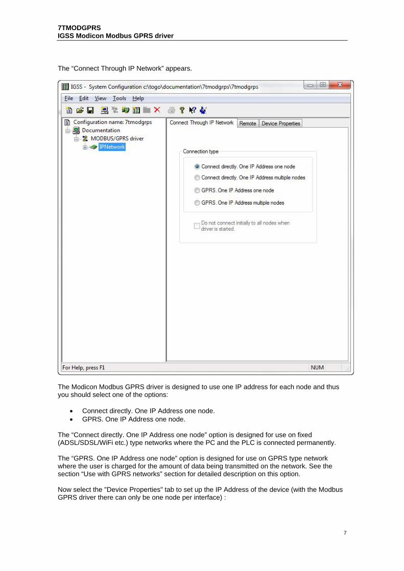
The “Connect Through IP Network” appears.
The Modicon Modbus GPRS driver is designed to use one IP address for each node and thus you should select one of the options:
Connect directly. One IP Address one node. GPRS. One IP Address one node.
The “Connect directly. One IP Address one node” option is designed for use on fixed (ADSL/SDSL/WiFi etc.) type networks where the PC and the PLC is connected permanently. The “GPRS. One IP Address one node” option is designed for use on GPRS type network where the user is charged for the amount of data being transmitted on the network. See the section “Use with GPRS networks” section for detailed description on this option. Now select the "Device Properties" tab to set up the IP Address of the device (with the Modbus GPRS driver there can only be one node per interface) :

7TMODGPRS IGSS Modicon Modbus GPRS driver
8
TCP/IP Parameters : Local IP Address : is only used for multihomed setups, and should normally be left alone. Local Port number : same as above. Remote IP Address : The IP address of the PLC Remote Port number : The port number of the PLC, standard is 502

7TMODGPRS IGSS Modicon Modbus GPRS driver
9
Each PLC node requires a few fundamental parameters: IGSS node number: This is the node number which IGSS uses to reference a unique PLC. This node number is required when binding and IGSS atom (tag) to a register in the PLC. Any number from the drop down list can be used. Modbus Unit ID : This number corresponds to the Modbus ID of the PLC, please note that many Modbus PLCs won't respond if requests are sent using a wrong Modbus ID. Processor type: Click this drop down box to select the PLC type (see screenshot above). STD Modbus/GPRS are a generic Processor type and used in most cases, the rest is for specific hardware.

7TMODGPRS IGSS Modicon Modbus GPRS driver
10
3.1 CONFIGURING THE OBJECTS
Once the driver and the PLC nodes have been defined, IGSS Objects and Atoms can be linked to process variable in the PLC. Various different types of PLC memory can be accessed for read/write operations using the driver. By using the “Edit Mapping” tab in the object properties dialog you can specify the binding between the object’s atoms and the PLC process variables. Start by selecting an atom and select the 7TMODGPRS driver in the “Driver” drop down list:
Now select the desired PLC node number and continue by setting be desired Device. Then specify the number (register number within the device type). Note that the corresponding Mnemonic is displayed and updated as you select the appropriate parameters. This is a help to make sure you always bind to the correct process variable. Continue this process for each atom on the object and save the parameters by clicking the OK button when finished.
7TMODGPRS IGSS Modicon Modbus GPRS driver
11
4 USE WITH GPRS NETWORKS
The IGSS Modicon Modbus GPRS driver is, as the name suggests designed for GPRS, however it can function in a wired/wireless LAN setting where the IGSS PC and the PLC’s are considered to be directly connected. However the 7TMODGPRS interface driver can also be used on other types of IP based networks as for example GPRS networks. GPRS networks basically work as a normal IP network except that there will be a toll (cost) associated with the amount of data you transmit on the network. The toll either comes as a cost pr. Mega Byte of data you put in the “wire”, or as a flat rate agreement with the GPRS provider which limits the amount of data you are allowed to put on the wire within a certain amount of time. This is in contrast to traditional LAN/WAN where the cost of the infrastructure normally doesn’t depend on the amount of data you put on the wire once the infrastructure (LAN/WAN network) is established. The IGSS Modicon Modbus GPRS driver allows you to set up the driver so that it will minimize the amount of data on the wire and thus minimize the cost associated with using GPRS type networks (or other types of toll based networks). If you don’t care about the toll on data traffic on the GPRS network then you can treat the GPRS network as any other LAN/WAN and just skip this section of the manual.

7TMODGPRS IGSS Modicon Modbus GPRS driver
12
To enable this mode for the driver select the “GPRS. One IP Address one node” option as shown above. When this option is enabled you can design a schedule which the driver will use when connecting to the PLC node. Select the node and switch to the “Remote connection” pane:

7TMODGPRS IGSS Modicon Modbus GPRS driver
13
In the “Connection Scheduling” section you can design a connection schedule either by entering specific points in time during the day where the driver will establish connection or you can enter a fixed time interval where the driver will establish connection – or a combination of both specific points in time and fixed intervals. Based on this schedule the driver will connect to the PLC and read all configured data points (i.e. all the tags you have defined in that node). Once the driver have read all the data it will stay idle until the next scheduled connection. Using this schedule dramatically reduces the amount of data on the wire – but of course this comes at the price of not actually being connected continuously. In the “Connection hold time” section you might want to specify how long the driver should keep the connection “open” it either the user sends a command or if the user forces the driver to establish a connection through a dialup/connection object. The “Normal connect hold time” option allows you to define how many seconds the driver will stay connected (online) if the user forces the driver to make a connection to the PLC. The “Send cmd connect hold time” option allows you to specify how many seconds the driver will stay online one the PLC node after the user has send a command. This latter is useful if the user should be able to see the response of the command which he/she has just sent.

7TMODGPRS IGSS Modicon Modbus GPRS driver
14
Once you are done defining the connection schedule continue to the “Connection Misc.” pane:
Since the driver is not continuously connected to the PLC you might want the PLC to store one or historical data in designated areas in the PLC and let the driver fetch and timestamp these data when it is online. If you e.g. want the driver to only be online each 4 hours but require some important tags to be stored in the IGSS system each 5 minutes (e.g. for reporting or trending) then you can use the “Collecting Historical Data” option to define where the data are stored. Click the “Settings” button to bring up the dialog used to define the layout of the historical data: The dialog contains one row for each historical tag you want to define. The first 3 columns (Data Group, Word Offset, Word Length) contain the fields to define where and how the data will be stored in IGSS. These parameters are used to bind the data to specific objects.

7TMODGPRS IGSS Modicon Modbus GPRS driver
15
Data Group: This field should always be set to 0. This is a fixed value which is used by the IGSS Modicon Modbus GPRS Driver to recognize that this is historical data. The value 512 maps to the Memory Type “Local Code0”. Word Offset: This field id used to distinguish between the different historical data tags. It is recommended to consequtive starting at 1 (one). The value of this field corresponds to the “Word Offset” parameter in the “Edit Mapping” dialog when we bind the historical data to specific objects. See details below. Word Length: This parameter is used to tell the driver the size of each of the historical data points. This should be set to 1 if the historical data is a 16 bit data type and it should be set to 2 if the historical data is a 32 bit data type. Chan. Node: This parameter tells the driver which history channel it should access, it is only available for some Processor Types, like the Grundfos CU361. Technical note: IGSS requires time stamped data to ALWAYS come in a time synchronious sequence with the oldest values first. This is automatically taken care of by the driver. When binding the historical data series to IGSS objects you should set the “Memory Type” to “Local Code0” and then select a “Word Offset” which matched the “Word Offset” of one of the historical data series you have just defined:

7TMODGPRS IGSS Modicon Modbus GPRS driver
16
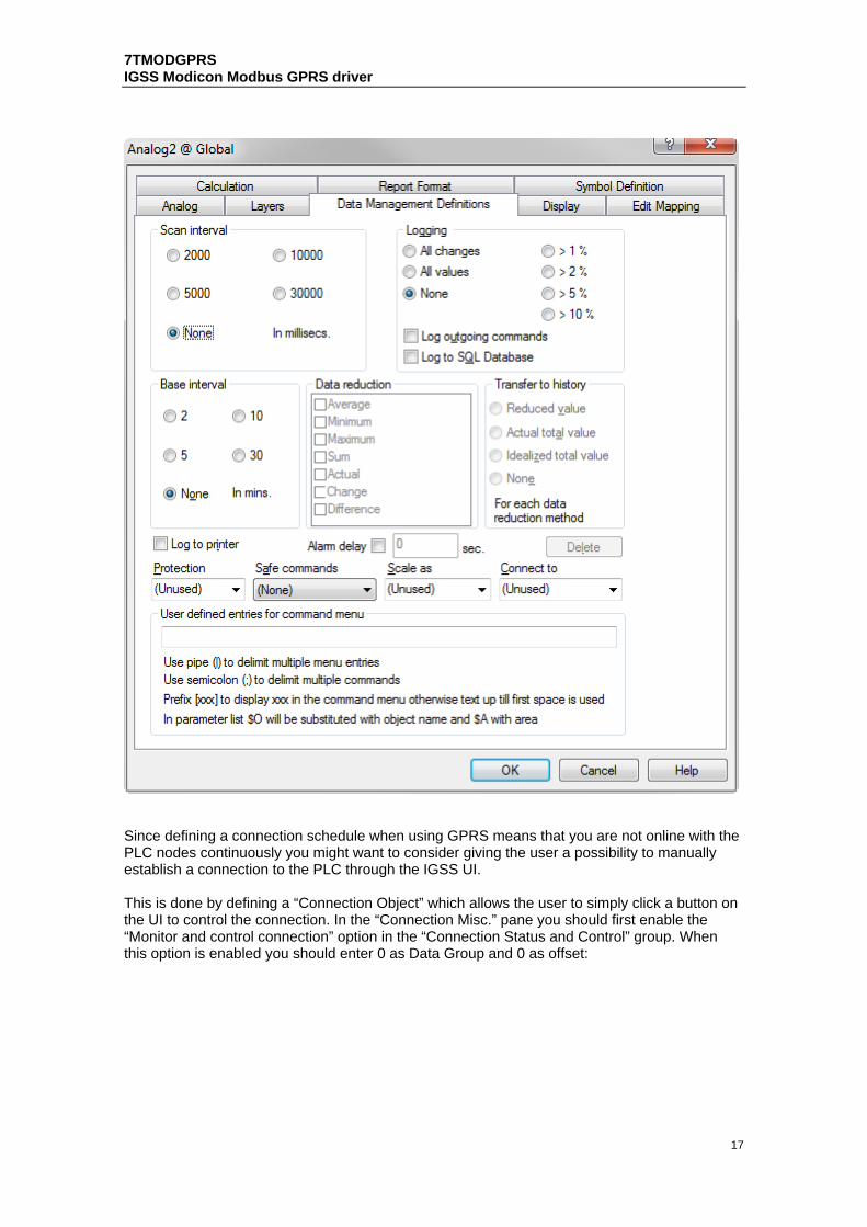
Make sure the I/O mode is set to “In”. It is VERY IMPORTANT that you set the scan interval to “None” in the “Data Management Definitions” pane. This is because that the scan interval doesn’t make sense for historical data series and thus should be disabled by setting the “Scan interval” parameter to “None”:
7TMODGPRS IGSS Modicon Modbus GPRS driver
17
Since defining a connection schedule when using GPRS means that you are not online with the PLC nodes continuously you might want to consider giving the user a possibility to manually establish a connection to the PLC through the IGSS UI. This is done by defining a “Connection Object” which allows the user to simply click a button on the UI to control the connection. In the “Connection Misc.” pane you should first enable the “Monitor and control connection” option in the “Connection Status and Control” group. When this option is enabled you should enter 0 as Data Group and 0 as offset:

7TMODGPRS IGSS Modicon Modbus GPRS driver
18
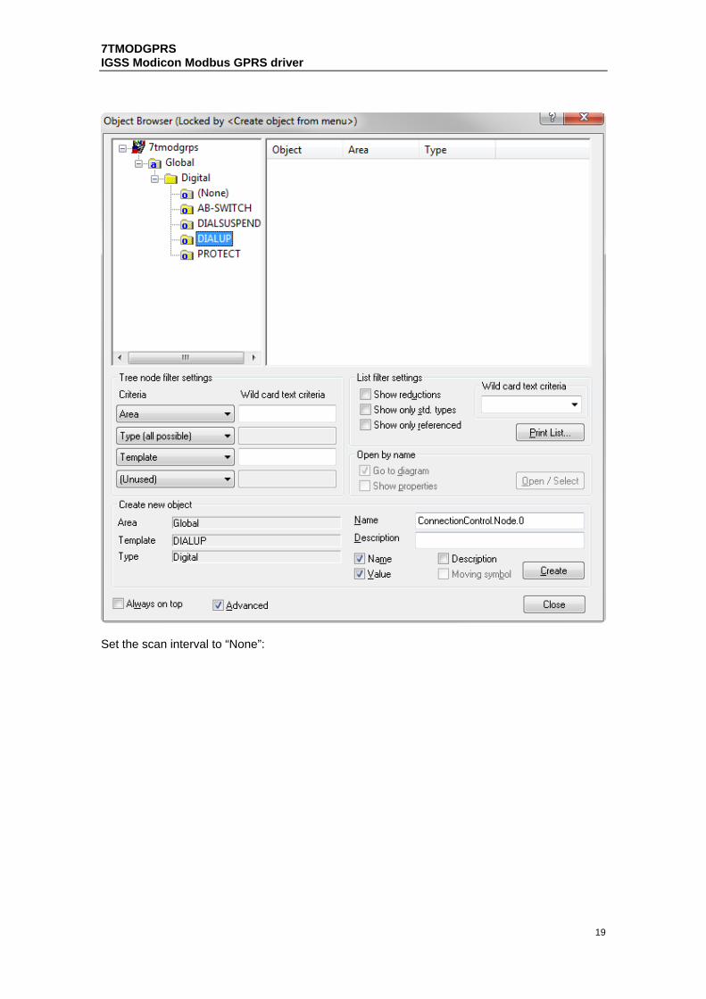
In the IGSS definition module you should then create a new digital object based on the build-in template called “DIALUP”:
7TMODGPRS IGSS Modicon Modbus GPRS driver
19
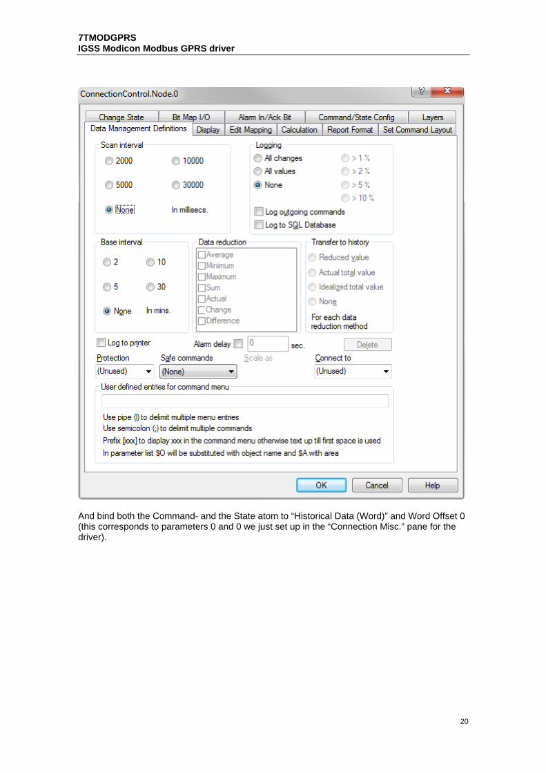
Set the scan interval to “None”:
7TMODGPRS IGSS Modicon Modbus GPRS driver
20
And bind both the Command- and the State atom to “Historical Data (Word)” and Word Offset 0 (this corresponds to parameters 0 and 0 we just set up in the “Connection Misc.” pane for the driver).

7TMODGPRS IGSS Modicon Modbus GPRS driver
21
If you want to use e.g. a Command Field mimic to allow the user to control the connection state to the PLC node then you could define something like this:

7TMODGPRS IGSS Modicon Modbus GPRS driver
22

7TMODGPRS IGSS Modicon Modbus GPRS driver
23
5 PERFORMANCE AND THROUGHPUT
The driver is designed for maximum throughput on a GPRS network. On a standard PC you should expect a throughput of 20+ request/response cycles pr. minute. Each PLC node is handled concurrent and independently. This means that if you add more PLC’s to the system then the throughput pr. PLC should only be affected marginally provided that the GPRS Modem throughput is sufficient. IMPORTANT NOTICE: The IGSS communication engine optimizes communication throughput by seeking to group data whenever possible. This means that if the communication engine is required to read e.g. word offset 1 and word offset 31 then it will read data registers 1, 2, through to word offset 31 as a block. This is much more efficient than reading the two data registers using two separate read requests.

7TMODGPRS IGSS Modicon Modbus GPRS driver
24
6 ERROR CODES
This section describes the error codes specific to the IGSS 7TMODGPRS interface driver. While troubleshooting communication- or addressing problems the Driver Test Application might be useful to display error codes reported by the driver. 0x4001: _7TTCP_OPEN_SOCKET_FAILED Cause: Unable to open a stream socket Action: Check that WinSock is present Subcode: windows errorcodes 0x4002: _7TTCP_BIND_SOCKET_FAILED Cause: Unable to bind to socket Action: Check if local IP address and port is used twice in the same configuration Subcode: windows errorcodes 0x4003: _7TTCP_CONNECT_SOCKET_FAILED Cause: Unable to connect to remote PLC. Action: verify that the PLC IP Address and Port is correct and that it is online by pinging the device using the IP Address and Port supplied for the node in sysconfig. Subcode: windows errorcodes 0x4004: _7TTCP_SEND_SOCKET_FAILED Cause: Unable to send requests to PLC. Action: verify that it is possible to ping the device Subcode: windows errorcodes 0x4005: _7TTCP_RECV_SOCKET_FAILED_FF Cause: Session closed by remote PLC Action: None, the driver will try to reconnect. Subcode: windows errorcodes 0x4006: _7TTCP_RECV_SOCKET_FAILED_00 Cause: Session closed by remote PLC Action: None, the driver will try to reconnect. Subcode: windows errorcodes

7TMODGPRS IGSS Modicon Modbus GPRS driver
25
0x4007: _7TTCP_RECV_NO_MSG Cause: Messagepool empty Action: Increase number of messages in Driver Setup 0x4008: _7TTCP_RECV_MSG_TOO_LONG Cause: Message longer than 255 bytes received Action: Reduce segment size in remote server 0x4009: _7TTCP_RECV_TIMEOUT 0x4009 Cause: PLC has not responded within the specified time. Action: None, driver will retry. If the problem persists please contact 7T Support.