slide show 8: define templates - igss.com - creating templates.pdf · on the ”edit mapping”...
TRANSCRIPT

INSIGHT
AND
OVERVIEW
Slide Show 8:
Define Templates

Overview
• What is an IGSS template ?
• Purpose of a template
• Alarm indication and acknowledgment
• Settings inherited by template-based objects

What is an IGSS template ?
• Templates can be made for analog, table, counterand digital object types
• Use templates when a number of processcomponents share several properties
• The real process components (IGSS objects) may bebased on a template
• Template-based objects will subscribe to changes in the template

Purpose of a template
• Use templates-only functionality– Freely name digital states and commands
– Define valid commands for digital objects
– Define digital alarms on digital and analog objects
– Reuse symbols from template for all object types
• Save time– Template-based objects merely need a new object name and unique PLC
addresses. The remaining properties are inherited from the template.
• Ensure consistency– One template – many objects
• Fast updating of objects– Change the template once to update multiple objects in the configuration

Create, edit, delete templates
Template menu
Object types
supported
Template name
Recommendation is
ALL CAPS for template names
Normal case for object names
Optional description
Copy properties from
another template
Templates defined in the ”Global” area
can be used in the entire configuration.
Templates defined in other areas are local.

Digital Templates

Digital templates
Summary• States and commands
– Define the number of states and commands you need(Bit Map I/O tab)
– Freely name the states and commands (States and Commands tab)– Define valid commands for each state (Command/State Config tab)
• Alarm indication and acknowledgment– Define the alarm bits you need (Alarm In/Ack Bit tab)– Define one or more alarms per template– Define the operator’s acknowledgment of the alarm from IGSS– Send the PLC’s acknowledgment bit back to IGSS– Define alarm inhibit bits
• Symbol definition– Save color and symbol selections in the template

States and commands (1)
STEP 2:
Define the number of
command bits you need
(f.ex. 2 bits for 4 commands)
STEP 1:
Define the number of
state bits you need
(f.ex. 2 bits for 4 states)
STEP 3:
Select the first state (initially
named ”<-0”), type the name in the
box and click ”Add State”.
Repeat for all states.
STEP 4:
Select the first command (initially
named ”<-0”), type the name in the
box and click ”Add Command”.
Repeat for all commands.
Single bits
Normally two bits will give four states
(00, 01, 10, 11). But using ”Single Bits”
IGSS will read the bits from left to right.
The first bit set is registered,
the remaining ones ignored.
Single bits for displays is used to show
the state of the individual bit, f.ex.
a panel of lamps that are on or off.
This tab is only
visible in the template,
not on the object.

States and commands (2)
Configuration of valid commands
STEP 1:
Choose a state
STEP 2:
Select the valid
command(s) for that state.
Only valid commands will be
available during supervision.
STEP 3:
Choose the default
command for the state.
The default command
will be emphasized for
the operator in the
Supervise program.

PLC addressing – General rules
• General rules– Plan the PLC memory layout from the start– Separate input (f.ex. analog values or digital states) from
output (f.ex. analog setpoints or digital commands )– In case of address conflicts, output takes priority over input
• Polled communication– Locate process components with the same scan interval in the
same memory block of the PLC to optimize data communicationbetween IGSS and the PLC. The fewer fetches or scan records, the more effective PLC communication.
• Event-oriented communication– Values from the PLC are only sent to IGSS in case of changes.
The event-oriented communication must be programmed in the PLC. On the Data Management Definitions tab, select ”None” under ”Scan interval”.A few drivers, f.ex. the OPC Client-Side Driver, will force the setting ”None” under ”Scan interval”.

PLC addressing – Commands
• Do not place commands from different objects in the same word !!
• In most cases, a digital command will take up 16 bits (one word)
• Some PLC drivers/communication protocols support 1-bit or 8-bit
addressing (examples: COMLI, MODBUS and SIMATIC)

PLC addressing – Commands
Obj. DG Word Bit
m1 10 1 0
m2 10 2 0
m3 10 3 0
m4 10 4 0
Template = MOTOR_1
• Choose atom and I/O mode=”Out”
• Choose driver and node number
• Choose data group and external type
• Leave word offset and bit offset as is
Object = m1, m2, m3, m4
• Type relevant word offset
PLC addresses

PLC addressing – States
• Different states for the same object cannot be placed in different data registers
• Digital states can be packed inside a data register to optimize the use of PLC memory and to make communication more effective

PLC addressing – States
Obj. DG Word Bit
m1 11 1 0
m2 11 1 2
m3 11 1 4
m4 11 1 6
Template = MOTOR_1
• Choose atom and I/O mode=”In”
• Choose driver and node number
• Choose data group and external type
• Leave word offset and bit offset as is
Object = m1, m2, m3, m4
• Type relevant word offset
• Type relevant bit offset
PLC addresses
2 bits used per object.

Alarm indication and
acknowledgement (1)
STEP 1:
Define alarm indication bits
(+) and alarm acknowledge-
ment bits (*) ”To PC”.
STEP 2:
Define alarm acknowledgement
bits (*) ”From PC”.
This is the operator’s acknow-
ledgement from the Alarm list.
It acknowledges all alarm
indication bits set.
STEP 3:
If more than one alarm
can be active at a time,
select the ”Alarms”
check box.
If not set, only the last
alarm will be visible in the
Alarm List.
STEP 4:
Choose either ”Individual”
or ”Consecutive” alarm
numbers. In the latter case,
only one alarm number
must be chosen on the
”Edit Mapping” tab.

Alarm indicationDefinition
Two alarm indication bits (+) are defined
on the ”Alarm In/Ack Bit” tab.
The PLC address is specified as the
”Alarm-In” atom on the ”Edit Mapping” tab.
Data Group 11PLC When one of these bits is raised, the
corresponding alarm text occurs in the
Alarm List. 15 14 13 12 11 10 9 8 7 6 5 4 3 2 1 0
Word 0
Word 1
Word 2
Word 3
Word ...
Word ...
Word ...
Word ...
Word ...
Word ...
Word 99
Word 100
Word 101 x x

Alarm acknowledgement
The operator acknowledges the
alarm. The bit is sent to the PLC
address specified for ”Alarm-Out”
on the ”Edit Mapping” tab.
The PLC program registers the operator acknowledgement and
returns a confirmation bit to IGSS. This the bit specified as * in the
”To PC” field on the ”Alarm In/Ack Bit” tab.
The PLC address is specified is the ”Alarm-In” atom on the ”Edit Mapping” tab.
When IGSS receives the PLC’s acknowledgement, the alarm
is acknowledged in IGSS. It typically changes color in the Alarm List
and is moved to the ”Alarm Log”.

PLC addressing – Summary
Obj. DG Word Bit
m1 10 1 0
m2 10 2 0
m3 10 3 0
m4 10 4 0
Obj. DG Word Bit
m1 11 1 0
m2 11 1 2
m3 11 1 4
m4 11 1 6
Obj. DG Word Bit
m1 10 101 0
m2 10 102 0
m3 10 103 0
m4 10 104 0
Commands States
Alarm-out
Obj. DG Word Bit
m1 11 101 0
m2 11 101 1
m3 11 101 2
m4 11 101 3
Alarm-in (one alarm defined)

”Log outgoing
commands”
enabled will log all
outgoing operator
commands like
start/stop pump.
This setting also
logs changes
activated by
the calculation
function or by
VBA.
The three general tabs
Checking the ”Copy symbols
to template” box will include
the symbols in the template.
Template-based objects can
then inherit the symbols and
symbol colors.
Remember that if you have several
alarm indication bits, you must create
or choose the corresponding number of
alarm texts.
Choosing the ”Change”
reduction method will
register all state changes

Analog Templates

Analog templates (alarm bits)
Alarm numbers
Alarm numbers must be
”Consecutive”. First alarm
number is specified.
To PC
- Alarm indication (+)
- Alarm inhibit (|)
- Alarm ack. (*)
From PC
- Alarm inhibit (|)
- Limit exceeded (0)
- Alarm ack. (*)
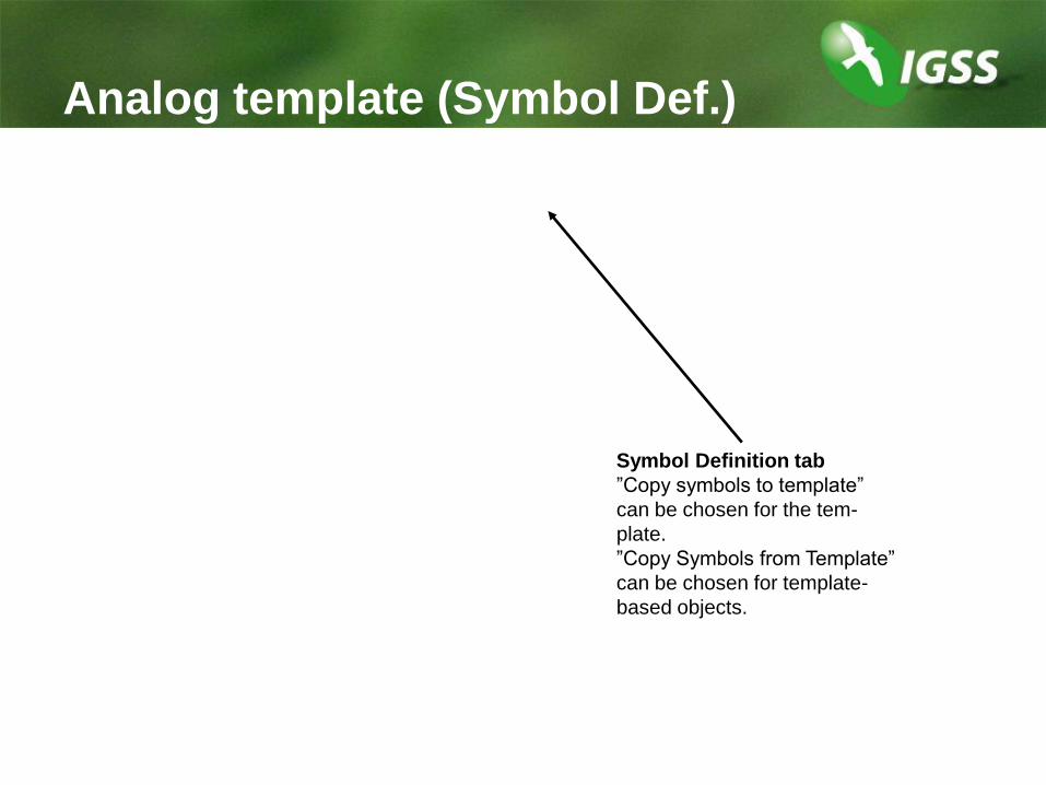
Analog template (Symbol Def.)
Symbol Definition tab
”Copy symbols to template”
can be chosen for the tem-
plate.
”Copy Symbols from Template”
can be chosen for template-
based objects.
Table and Counter Templates
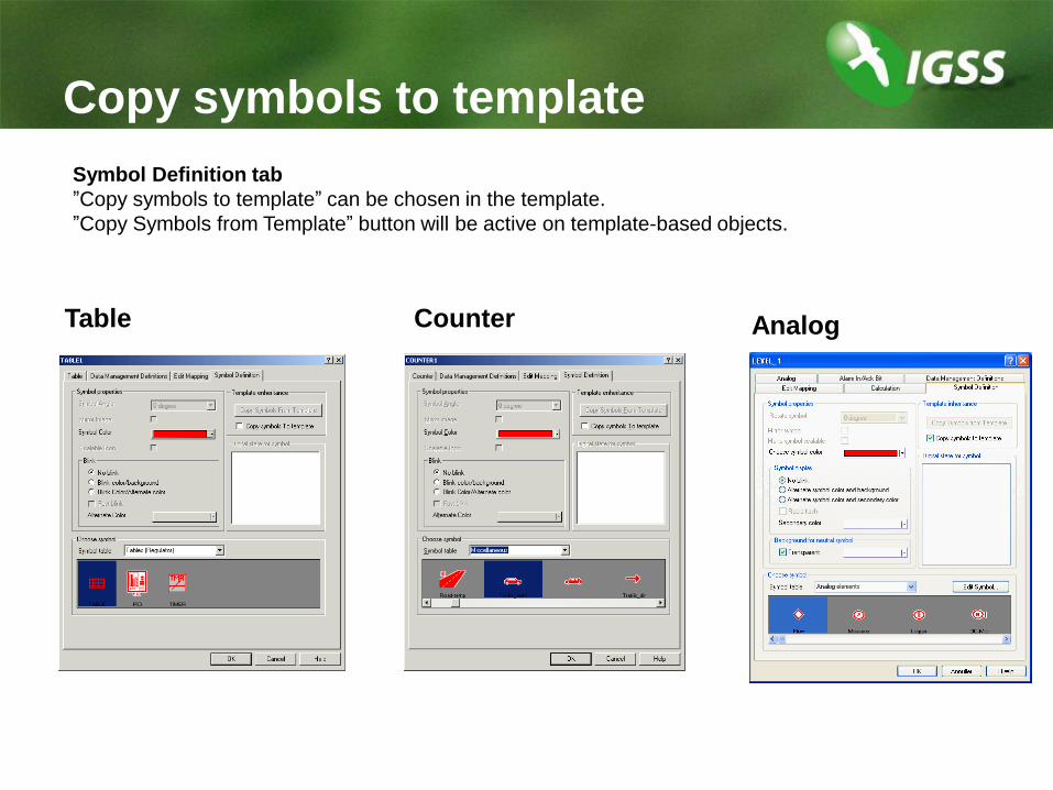
Table Counter Analog
Copy symbols to template
Symbol Definition tab
”Copy symbols to template” can be chosen in the template.
”Copy Symbols from Template” button will be active on template-based objects.

Create Template-Based Objects

Create template-based objects (1)
STEP 1:
Right-click the diagram and
select descriptor.
STEP 2:
Select area, object type and template.
STEP 3:
Give the object
a unique name.
Click Create.

Create template-based objects (2)
STEP 4:
Click ”Copy Symbols from
Template”.
STEP 5:
Specify unique PLC
addresses (command)
STEP 6:
Specify unique PLC addresses
(state) – notice bit offset
STEP 7:
Click OK and
position the
symbol and text.

Create template-based objects (3)
Copy/paste of objects
STEP 1:
Select the symbol and
text on the diagram.
STEP 2:
Copy/Paste and
position new symbol.
STEP 3:
Change object name –
notice template name
Use Property Table View
to change names and PLC
addresses.

Create template-based objects (4)
STEP 4:
Specify PLC addresses
for all active atoms on
”Edit Mapping”.
STEP 5:
Click OK. The object is complete.

Settings Inheritedfrom Template

Settings inherited
The following settings are inherited when you change the templates:
Digital templates
• The number of states and commands
• The names of states and commands
• The configuration of valid commands
• The bit map of states and commands
Digital and analog templates
• The bit map of alarm indication and acknowledgement
All templates
• Alarm texts
• Symbol definition
(Via the Copy Symbols From Template button)

Settings not Inherited
The following settings are not inherited when you
change the templates:
• Driver and node number
• Settings on the Data Management
Definitions tab
• e.g. attachment of Protect objects
Solutions:
• Change the properties in the Property Table View
(Diagram menu) or
• Change the properties via the ODBC interface

Online Demo
Watch while the instructor does the following:
• Create a digital template
• Define state and command bits
• Name the states and commands
• Configure the valid commands
• Define alarm indication and acknowledgment bits
• Specify PLC addresses and alarm texts
Do Exercise 5 in the Exercises booklet after the demo.