737cdappdf
DESCRIPTION
BoeingTRANSCRIPT

This is the long awaited CDAP (Constant Desent Approach Procedures).
PROFILES
This procedure is to be used for
ALL APPROACHES
© MIKE RAY 2003
CONSTANT DESCENT APPROACH PROCEDURES
OK ... AT ALT HOLD ...OH YEAH ...SET COMPUTED TDZE
BOEING GLASS 737
PO BOX 1239, TEMECULA, CA 92562
© MIKE RAY 2003
published by UNIVERSITY of TEMECULA PRESS
© MIKE RAY 2003 2
GLASS 737 SUPER GUPPY SIMULATOR TECHNIQUES and PROCEDURES FOR STUDY AND REVIEW ONLY
CONSTANT DESCENT APPROACH PROCEDURES
MINIMA CRITERIA AT PRESENT (AND IN A STATE OF FLUX)
NO qualification or training required to fly CDAP precision approaches or Visuals to their published minimums.
For the Non-precision approaches:
Right now, even with a trained crew ........ 800/2,then at some point in the future, when FAA and Company decide, we can revert to published minimums.
EGPWS inop ............................................. 800/2Mixed crew (only one qualified) ................. 800/2No trained crewmembers ........................ 800/2and must fly “old dive and drive”
Soon … everything we held dear and sacred will become passe and “old school.” I am referring to the “dive and drive” technique
of flying the approach that we have come to appreciate.
Sometime in the next 6 to 9 months, the switch-over will occur to CDAP (Constant Descent Approach Procedures). No one seems
to know just when or by what mechanism the pilots will be notified; however that day will come when it is determined that all
the pilots are qualified.
Here is a Mike Ray view of what is in the mill right now. Look it over and give me a notification if it is like what you encounter at
the training center.
Introducing
YIPPEE-KI-YO-KI-YAY!!! No more of that overly complex and virtually impossible to figure PDP (Planned Descent Point) calculation required. However, before you get all excited, the PDP has been replaced with an equally distracting and annoying VERTICAL SPEED COMPUTATION.
NO MORE PDP CALCULATION REQUIRED!
PO BOX 1239, TEMECULA, CA 92562
© MIKE RAY 2003
published by UNIVERSITY of TEMECULA PRESS
© MIKE RAY 2003 3
GLASS 737 SUPER GUPPY SIMULATOR TECHNIQUES and PROCEDURES FOR STUDY AND REVIEW ONLY
CONSTANT DESCENT APPROACH PROCEDURESHas also been referred to as:
CANPA: Constant Angle Non Precision Approachand
CROD: Constant Rate Of Descent
A BRIEF DISCUSSION ABOUT:
CDAP (Constant Descent Approach Procedures) MUST be used.
Stipulations in the agreement are that once the crews are trained, then
CDAP will be the ONLY type of approach to be used
… and further, it has been determined that
“ALL” approaches, whether precision, non-
precision, or Visual will be flown using the CDAP.
Now, on the surface that all looks like finally we will be done away with the old “dive and drive” and a much more modern and simpler approach model will be used, making life easier on the working line crews.
Whoops! Not so fast there, Ace. It seems that the “dive and drive” with all it’s warts and
hickeys is still the operative vertical navigation technique up to the FAF (Final Approach Fix) and the
CDAP is to be used ONLY in that Final Approach Segment (FAS) from the FAF to landing/go-around.
PO BOX 1239, TEMECULA, CA 92562
© MIKE RAY 2003
published by UNIVERSITY of TEMECULA PRESS
© MIKE RAY 2003 4
GLASS 737 SUPER GUPPY SIMULATOR TECHNIQUES and PROCEDURES FOR STUDY AND REVIEW ONLY
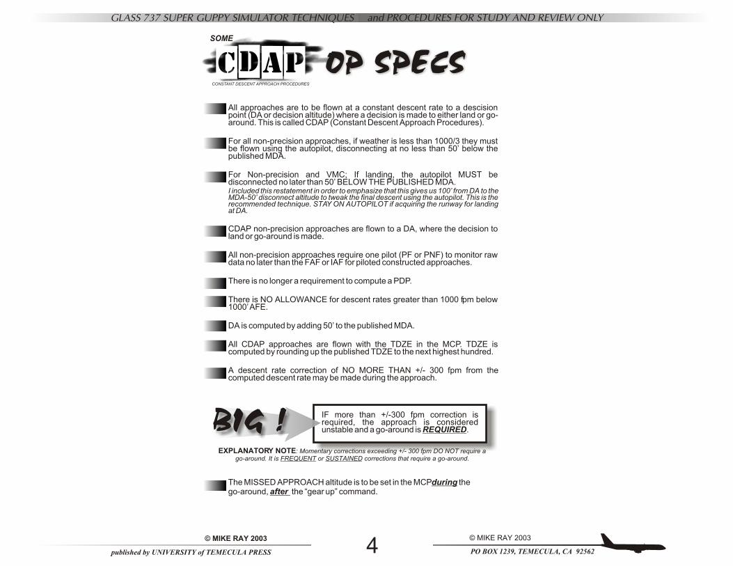
All approaches are to be flown at a constant descent rate to a descision point (DA or decision altitude) where a decision is made to either land or go-around. This is called CDAP (Constant Descent Approach Procedures).
For all non-precision approaches, if weather is less than 1000/3 they must be flown using the autopilot, disconnecting at no less than 50’ below the published MDA.
For Non-precision and VMC; If landing, the autopilot MUST be disconnected no later than 50’ BELOW THE PUBLISHED MDA. I included this restatement in order to emphasize that this gives us 100’ from DA to the MDA-50’ disconnect altitude to tweak the final descent using the autopilot. This is the recommended technique. STAY ON AUTOPILOT if acquiring the runway for landing at DA.
CDAP non-precision approaches are flown to a DA, where the decision to land or go-around is made.
All non-precision approaches require one pilot (PF or PNF) to monitor raw data no later than the FAF or IAF for piloted constructed approaches.
There is no longer a requirement to compute a PDP.
There is NO ALLOWANCE for descent rates greater than 1000 fpm below 1000’ AFE.
DA is computed by adding 50’ to the published MDA.
All CDAP approaches are flown with the TDZE in the MCP. TDZE is computed by rounding up the published TDZE to the next highest hundred.
A descent rate correction of NO MORE THAN +/- 300 fpm from the computed descent rate may be made during the approach.
CONSTANT DESCENT APPROACH PROCEDURES
OP SPECSSOME
IF more than +/-300 fpm correction is required, the approach is considered unstable and a go-around is REQUIRED.
The MISSED APPROACH altitude is to be set in the MCPduring the go-around, after the “gear up” command.
BIG !EXPLANATORY NOTE: Momentary corrections exceeding +/- 300 fpm DO NOT require a
go-around. It is FREQUENT or SUSTAINED corrections that require a go-around.
PO BOX 1239, TEMECULA, CA 92562
© MIKE RAY 2003
published by UNIVERSITY of TEMECULA PRESS
© MIKE RAY 2003 5
GLASS 737 SUPER GUPPY SIMULATOR TECHNIQUES and PROCEDURES FOR STUDY AND REVIEW ONLY
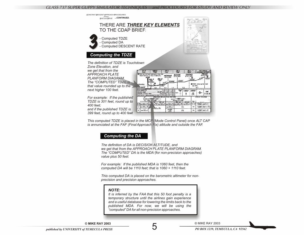
The definition of TDZE is Touchdown Zone Elevation, andwe get that from the APPROACH PLATE PLANFORM DIAGRAM.The “COMPUTED” TDZE is that value rounded up to the next higher 100 feet.
For example: If the published TDZE is 301 feet, round up to 400 feet; and if the published TDZE is 399 feet, round up to 400 feet.
This computed TDZE is placed in the MCP (Mode Control Panel) once ALT CAP is annunciated at the FAF (Final Approach Fix) altitude and outside the FAF.
CONSTANT DESCENT APPROACH PROCEDURESversus
DIVE and DRIVE
THERE ARE THREE KEY ELEMENTS TO THE CDAP BRIEF:
- Computed TDZE- Computed DA- Computed DESCENT RATE
...CONTINUED.
Computing the TDZE
Computing the DA
The definition of DA is DECISION ALTITUDE, andwe get that from the APPROACH PLATE PLANFORM DIAGRAM.The “COMPUTED” DA is the MDA (for non-precision approaches) value plus 50 feet.
For example: If the published MDA is 1060 feet, then the computed DA will be 1110 feet; that is 1060 + 1110 feet.
This computed DA is placed on the barometric altimeter for non-precision and precision approaches.
NOTE:It is inferred by the FAA that this 50 foot penalty is a temporary structure until the airlines gain experience and a useful database for lowering the limits back to the published MDA. For now, we will be using the “computed” DA for all non-precision approaches.
3
PO BOX 1239, TEMECULA, CA 92562
© MIKE RAY 2003
published by UNIVERSITY of TEMECULA PRESS
© MIKE RAY 2003 6
GLASS 737 SUPER GUPPY SIMULATOR TECHNIQUES and PROCEDURES FOR STUDY AND REVIEW ONLY
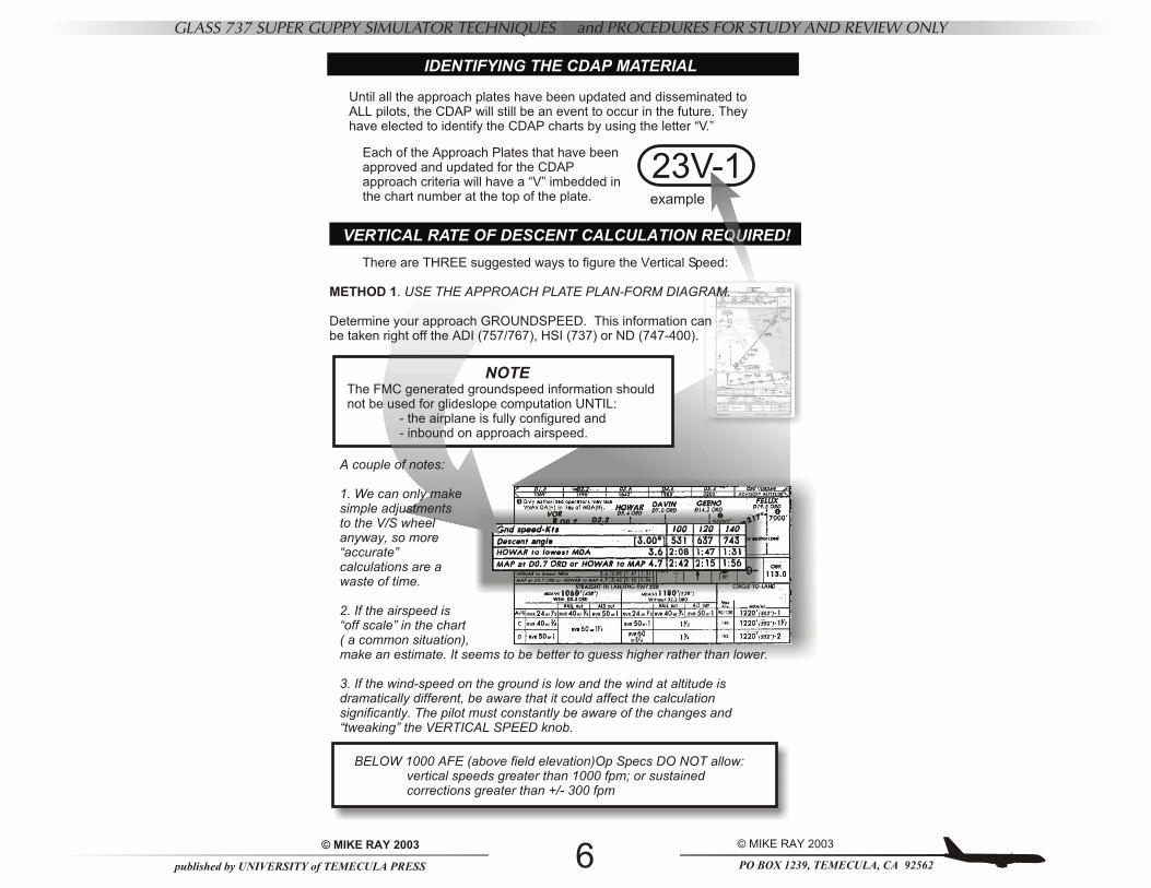
VERTICAL RATE OF DESCENT CALCULATION REQUIRED!
IDENTIFYING THE CDAP MATERIAL
BELOW 1000 AFE (above field elevation)Op Specs DO NOT allow:vertical speeds greater than 1000 fpm; or sustainedcorrections greater than +/- 300 fpm
NOTEThe FMC generated groundspeed information should not be used for glideslope computation UNTIL:
- the airplane is fully configured and - inbound on approach airspeed.
A couple of notes:
1. We can only make simple adjustments to the V/S wheel anyway, so more “accurate” calculations are a waste of time.
2. If the airspeed is “off scale” in the chart ( a common situation), make an estimate. It seems to be better to guess higher rather than lower.
3. If the wind-speed on the ground is low and the wind at altitude is dramatically different, be aware that it could affect the calculation significantly. The pilot must constantly be aware of the changes and “tweaking” the VERTICAL SPEED knob.
There are THREE suggested ways to figure the Vertical Speed:
METHOD 1. USE THE APPROACH PLATE PLAN-FORM DIAGRAM.
Determine your approach GROUNDSPEED. This information can be taken right off the ADI (757/767), HSI (737) or ND (747-400).
Each of the Approach Plates that have been approved and updated for the CDAP approach criteria will have a “V” imbedded in the chart number at the top of the plate.
Until all the approach plates have been updated and disseminated to ALL pilots, the CDAP will still be an event to occur in the future. They have elected to identify the CDAP charts by using the letter “V.”
23V-1example
PO BOX 1239, TEMECULA, CA 92562
© MIKE RAY 2003
published by UNIVERSITY of TEMECULA PRESS
© MIKE RAY 2003 7
GLASS 737 SUPER GUPPY SIMULATOR TECHNIQUES and PROCEDURES FOR STUDY AND REVIEW ONLY
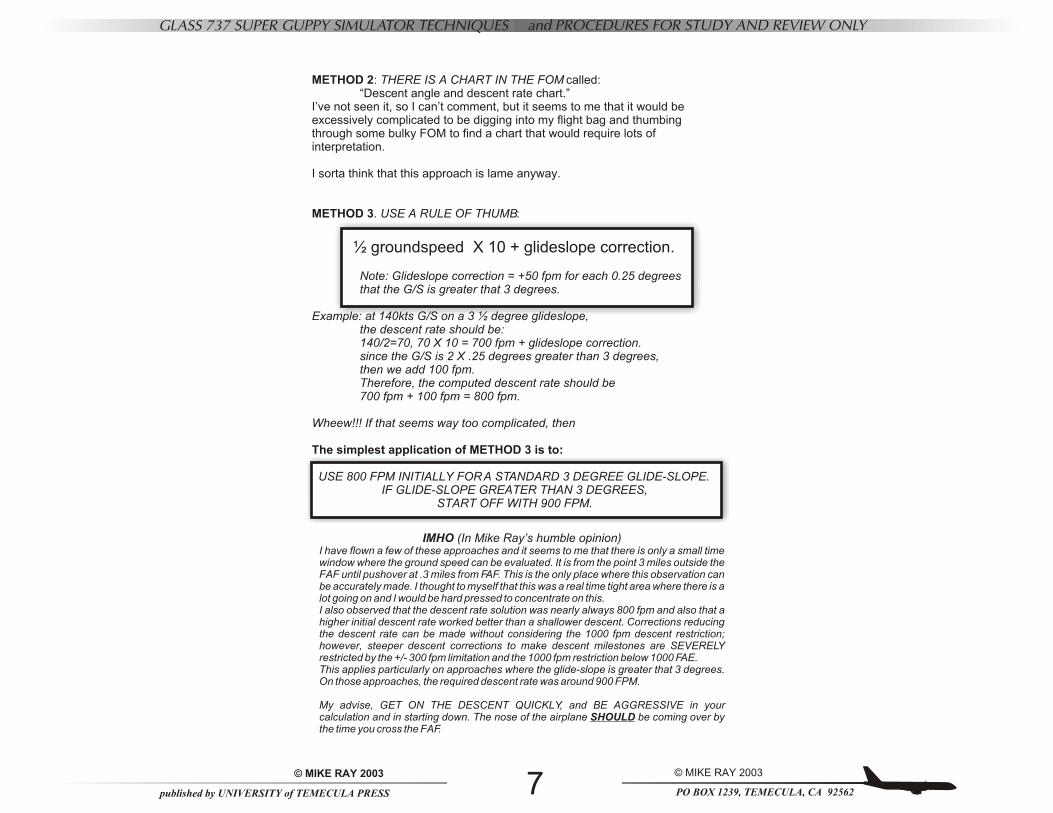
METHOD 2: THERE IS A CHART IN THE FOM called:“Descent angle and descent rate chart.”
I’ve not seen it, so I can’t comment, but it seems to me that it would be excessively complicated to be digging into my flight bag and thumbing through some bulky FOM to find a chart that would require lots of interpretation.
I sorta think that this approach is lame anyway.
METHOD 3. USE A RULE OF THUMB:
½ groundspeed X 10 + glideslope correction.
Note: Glideslope correction = +50 fpm for each 0.25 degrees that the G/S is greater that 3 degrees.
Example: at 140kts G/S on a 3 ½ degree glideslope, the descent rate should be:140/2=70, 70 X 10 = 700 fpm + glideslope correction.since the G/S is 2 X .25 degrees greater than 3 degrees, then we add 100 fpm.Therefore, the computed descent rate should be 700 fpm + 100 fpm = 800 fpm.
Wheew!!! If that seems way too complicated, then
The simplest application of METHOD 3 is to:
USE 800 FPM INITIALLY FOR A STANDARD 3 DEGREE GLIDE-SLOPE. IF GLIDE-SLOPE GREATER THAN 3 DEGREES,
START OFF WITH 900 FPM.
IMHO (In Mike Ray’s humble opinion)I have flown a few of these approaches and it seems to me that there is only a small time window where the ground speed can be evaluated. It is from the point 3 miles outside the FAF until pushover at .3 miles from FAF. This is the only place where this observation can be accurately made. I thought to myself that this was a real time tight area where there is a lot going on and I would be hard pressed to concentrate on this.I also observed that the descent rate solution was nearly always 800 fpm and also that a higher initial descent rate worked better than a shallower descent. Corrections reducing the descent rate can be made without considering the 1000 fpm descent restriction; however, steeper descent corrections to make descent milestones are SEVERELY restricted by the +/- 300 fpm limitation and the 1000 fpm restriction below 1000 FAE.This applies particularly on approaches where the glide-slope is greater that 3 degrees. On those approaches, the required descent rate was around 900 FPM.
My advise, GET ON THE DESCENT QUICKLY, and BE AGGRESSIVE in your calculation and in starting down. The nose of the airplane SHOULD be coming over by the time you cross the FAF.
PO BOX 1239, TEMECULA, CA 92562
© MIKE RAY 2003
published by UNIVERSITY of TEMECULA PRESS
© MIKE RAY 2003 8
GLASS 737 SUPER GUPPY SIMULATOR TECHNIQUES and PROCEDURES FOR STUDY AND REVIEW ONLY
CONSTANT DESCENT APPROACH PROCEDURES
TALK THROUGH
THIS !
THIS !
TDZE !
BRIEF
SET
SET DA !SET
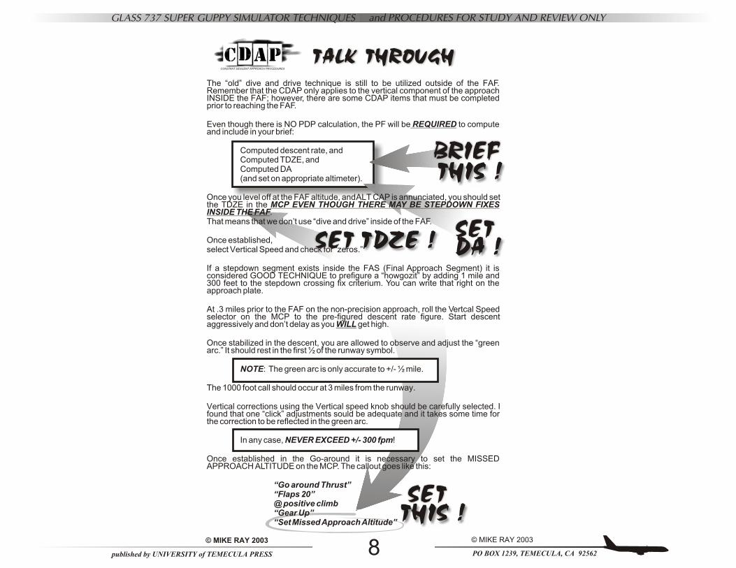
The “old” dive and drive technique is still to be utilized outside of the FAF. Remember that the CDAP only applies to the vertical component of the approach INSIDE the FAF; however, there are some CDAP items that must be completed prior to reaching the FAF.
Even though there is NO PDP calculation, the PF will be REQUIRED to compute and include in your brief:
Computed descent rate, andComputed TDZE, andComputed DA (and set on appropriate altimeter).
Once you level off at the FAF altitude, and ALT CAP is annunciated, you should set the TDZE in the MCP EVEN THOUGH THERE MAY BE STEPDOWN FIXES INSIDE THE FAF.That means that we don’t use “dive and drive” inside of the FAF.
Once established, select Vertical Speed and check for “zeros.”
If a stepdown segment exists inside the FAS (Final Approach Segment) it is considered GOOD TECHNIQUE to prefigure a “howgozit” by adding 1 mile and 300 feet to the stepdown crossing fix criterium. You can write that right on the approach plate.
At .3 miles prior to the FAF on the non-precision approach, roll the Vertcal Speed selector on the MCP to the pre-figured descent rate figure. Start descent aggressively and don’t delay as you WILL get high.
Once stabilized in the descent, you are allowed to observe and adjust the “green arc.” It should rest in the first ½ of the runway symbol.
NOTE: The green arc is only accurate to +/- ½ mile.
The 1000 foot call should occur at 3 miles from the runway.
Vertical corrections using the Vertical speed knob should be carefully selected. I found that one “click” adjustments sould be adequate and it takes some time for the correction to be reflected in the green arc.
In any case, NEVER EXCEED +/- 300 fpm!
Once established in the Go-around it is necessary to set the MISSED APPROACH ALTITUDE on the MCP. The callout goes like this:
“Go around Thrust”“Flaps 20”@ positive climb“Gear Up”“Set Missed Approach Altitude”
PO BOX 1239, TEMECULA, CA 92562
© MIKE RAY 2003
published by UNIVERSITY of TEMECULA PRESS
© MIKE RAY 2003 9
GLASS 737 SUPER GUPPY SIMULATOR TECHNIQUES and PROCEDURES FOR STUDY AND REVIEW ONLY
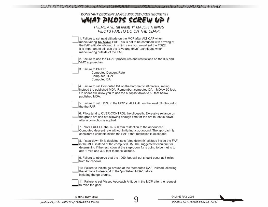
CONSTANT DESCENT ANGLE PROCEDURES SECRETS !
THERE ARE (at least) 11 MAJOR THINGSPILOTS FAIL TO DO ON THE CDAP:
1. Failure to set next altitude on the MCP after ALT CAP when maneuvering OUTSIDE FAF. This is not to be confused with arriving at the FAF altitude inbound, in which case you would set the TDZE.It is important to still use the “dive and drive” techniques when maneuvering outside of the FAF.
2. Failure to use the CDAP procedures and restrictions on the ILS and VMC approaches.
3. Failure to BRIEF:Computed Descent RateComputed TDZEComputed DA
4. Failure to set Computed DA on the barometric altimeters, setting instead the published MDA. Remember, computed DA = MDA + 50 feet. Op specs still allow you to use the autopilot down to 50 feet below published MDA.
5. Failure to set TDZE in the MCP at ALT CAP on the level off inbound to the the FAF.
6. Pilots tend to OVER-CONTROL the glidepath. Excessive reliance on the green arc and not allowing enough time for the arc to “settle down” after a correction is applied.
7. Pilots EXCEED the +/- 300 fpm restriction to the announced Computed descent rate without initiating a go-around. The approach is considered unstable inside the FAF if that restriction is exceeded.
8. If step-down fix is depicted, sets “step down fix” altitude inside the FAF in the MCP instead of the computed DA. The suggested technique for determining if the restriction at the step-down fix is going to be met is to add 1 mile and 300 feet to the fix altitude.
9. Failure to observe that the 1000 foot call-out should occur at 3 miles from touchdown.
10. Failure to initiate go-around at the “computed DA,” Instead, allowing the airplane to descend to the “published MDA” before initiating the go-around.
11. Failure to set Missed Approach Altitude in the MCP after the request to raise the gear.
WHAT PILOTS SCREW UP !
PO BOX 1239, TEMECULA, CA 92562
© MIKE RAY 2003
published by UNIVERSITY of TEMECULA PRESS
© MIKE RAY 2003 10
GLASS 737 SUPER GUPPY SIMULATOR TECHNIQUES and PROCEDURES FOR STUDY AND REVIEW ONLY
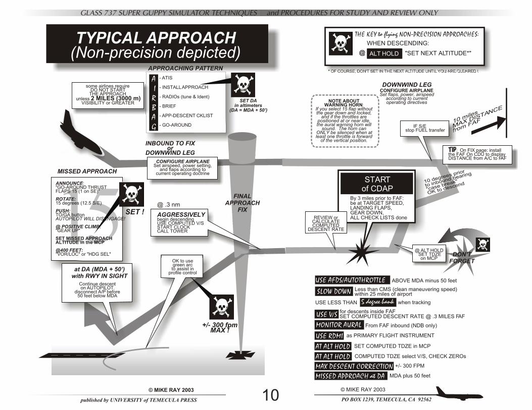
15ANNOUNCE:"GO-AROUND THRUSTFLAPS 15 (1 on SE)"
ROTATE:15 degrees (12.5 S/E)
PUSH:TO/GA buttonAUTOPILOT WILL DISENGAGE!
@ POSITIVE CLIMB:"GEAR UP"
SET MISSED APPROACHALTITUDE in the MCP
@400 FEET:"VOR/LOC" or "HDG SEL"
TYPICAL APPROACH(Non-precision depicted)
APPROACHING PATTERN
A IRBAG
OK to usegreen arcto assist in
profile control
FINALAPPROACH
FIX
- ATIS
- INSTALL APPROACH
- RADIOs (tune & Ident)
- BRIEF
- APP-DESCENT CKLIST
- GO-AROUND
INBOUND TO FIXor
DOWNWIND LEG
SET DAin altimeters
(DA = MDA + 50’)
+/- 300 fpmMAX !
SET !
SECOND TARGETPOINT
some airlines requireDO NOT START THE APPROACH
unless 2 MILES (3000 m) VISIBILITY or GREATER
@ .3 nm
AGGRESSIVELY begin descendingUSE COMPUTED V/SSTART CLOCKCALL TOWER
Continue descent on AUTOPILOT.
disconnect A/P before50 feet below MDA
at DA (MDA + 50’)with RWY IN SIGHT
MISSED APPROACH
CONFIGURE AIRPLANESet airspeed, power setting,
and flaps according to current operating doctrine
SLOW DOWN !Less than CMS (clean maneuvering speed) within 25 miles of airport
10 miles
MAX DISTANCE
from FAF
USE AFDS/AUTOTHROTTLE
for descents inside FAFSET COMPUTED DESCENT RATE @ .3 MILES FAF
when trackingUSE LESS THAN
ABOVE MDA minus 50 feet
USE V/S
5 degree bank
MONITOR AURAL
USE RDMI
AT ALT HOLD
AT ALT HOLD
MAX DESCENT CORRECTION
MISSED APPROACH at DA
as PRIMARY FLIGHT INSTRUMENT
SET COMPUTED TDZE in MCP
COMPUTED TDZE select V/S, CHECK ZEROs
+/- 300 FPM
MDA plus 50 feet
From FAF inbound (NDB only)
10 degrees prior
to inbound bearing
"case break"
OK to descend
DOWNWIND LEG
IF S/Estop FUEL transfer
REVIEW orCALCULATECOMPUTED
DESCENT RATE
TIP: On FIX page: install the FAF On CDU to displayDISTANCE from A/C to FAF
By 3 miles prior to FAF:be at TARGET SPEED,LANDING FLAPS,GEAR DOWN,ALL CHECK LISTS done
* OF COURSE, DON'T SET IN THE NEXT ALTITUDE UNTIL YOU ARE CLEARED !
START of CDAP
THE KEY to flying NON-PRECISION APPROACHES:
WHEN DESCENDING:
"SET NEXT ALTITUDE*"@@ ALT HOLD
DON'T FORGET
NOTE ABOUT WARNING HORN:
If you select 15 flap without the gear down and locked,
and if the throttles are positioned at or near idle, the aural warning horn will
sound. The horn can ONLY be silenced when at least one throttle is forward
of the vertical position.
CONFIGURE AIRPLANESet flaps, power, airspeed
according to current operating directives
@ ALT HOLD SET TDZE
on MCP

PO BOX 1239, TEMECULA, CA 92562
© MIKE RAY 2003
published by UNIVERSITY of TEMECULA PRESS
© MIKE RAY 2003 11
GLASS 737 SUPER GUPPY SIMULATOR TECHNIQUES and PROCEDURES FOR STUDY AND REVIEW ONLY
For additional copies, information, corrections, deletions,
complaints,diatribes, and vituperations …
or you just want to say Hi:
Captain (retired) Mike [email protected]: 909-698-3676
University of Temecula Press, Inc.42730 De Luz RoadMurrieta, CA 92562