722.9 introduction to mercedes
TRANSCRIPT

Introduction to the MERCEDES 722.9
Presented by: Steve Garrett
ATRA
Sponsored By:

722.9 TRANSMISSION
Some Information contained within this Presentation is courtesy of Mercedes- Benz Corporation

Today’s Presentation Sponsored By:

[email protected] Connections Handout Questions Survey

THANKS A Special Thanks To Mercedes Benz for the
information and help provided for this presentation.

• Features • * 5th generation of automatic transmission for
Mercedes • • Electronically controlled automatic gearbox • • Seven forward and two reverse speeds • • Transmission control module is: • - integrated into valve body assembly, ‘flash’ capable • • Torque converter operates in open or TCC slip
mode in all seven forward speeds • • Gear ratios achieved with four multi-disc brakes
and three multi-disc clutches (no free-wheeling units)
• • 3 planetary gear sets: 2 simple & 1 Ravigneaux

•Advantages • • Shift comfort / driving pleasure increased through
improved control of gear changes : • - Shorter computer reaction time by 0.1 second • - Downshifts shortened by up to 0.2 second • - Coasting downshifts shortened by 0.4 – 2.5 seconds • - 37 to 74 mph acceleration times shortened by 23 -
28% (depending on model) • • Fuel consumption reduced by up to 4% • • Noise levels reduced, due to lower engine speed in
5th, 6th & 7th gear at constant vehicle speed • • Flexible adaptation to vehicle and engine

• Transmission Application • • 722.9 transmission was offered starting in : • - as an option in new SLK (R171 - 09/04) • - standard equipment for new M Class (W164 - 2005) • - standard equipment for new R Class (W251 - 2005) • - standard equipment for new G Class (X164 - 2006) • - standard equipment on CLS 350 / 500 (late 2004) • - standard equipment on E350 (late 2004) • • 722.9 for W164 / W251 / X164 is equipped with shift by wire (no shift rod). Instead an electric control module is fitted to operate shift control valve and monitor position via a positioning sensor. * • Transmission is also referred to as: - NAG 2 (Neues Automatische Getriebe 2) (New Automatic Gearbox 2) - or 7G-Tronic

• Shift Program (Customer’s Perspective)
• • Basic shift program can be varied (same as 722.6), using S/C button on Electronic Shifter Module (ESM)
• “S” (Sport): First gear start “C” (Comfort): Second gear start • Normal shift points Earlier up-shifts and later downshifts • Reverse gear 1 (-3.416:1) Reverse gear 2 (-2.231:1) • Note: Transmission will start in first gear if any of the
following apply: • - 1st gear manually selected - ¾ to full throttle applied from
stationary start • - engine cold (catalytic converter warm-up) • • Shift into Optimal Gear (SOG) software as known from
previous models • • Up-shifts and downshifts are influenced based on the
current driving style and loads (similar to 722.6) • • Shift interlock performed by Electronic Shifter Module (ESM)
as before on 722.6

FLUID
• Transmission Fluid • • Requires a newly developed transmission fluid (ATF
3353) with the following properties: • - Higher friction consistency • - Higher thermal stability • - Improved temperature behavior • • Oil suppliers are Shell & Fuchs Europe • • Only use this approved fluid: Currently a 1 liter bottle
is available (MB part number A001 989 45 03 10) • • No scheduled maintenance • • Can also be used in 722.3 / .4 / .5 / .6

• Transmission Fluid Level • • No dipstick or dipstick tube • • Fluid level checked using overflow method • • Oil pan has overflow pipe clipped onto pan,
above drain plug • • Fluid level must be checked at specified
transmission fluid temperature • • Special filling station used to add fluid
through drain plug
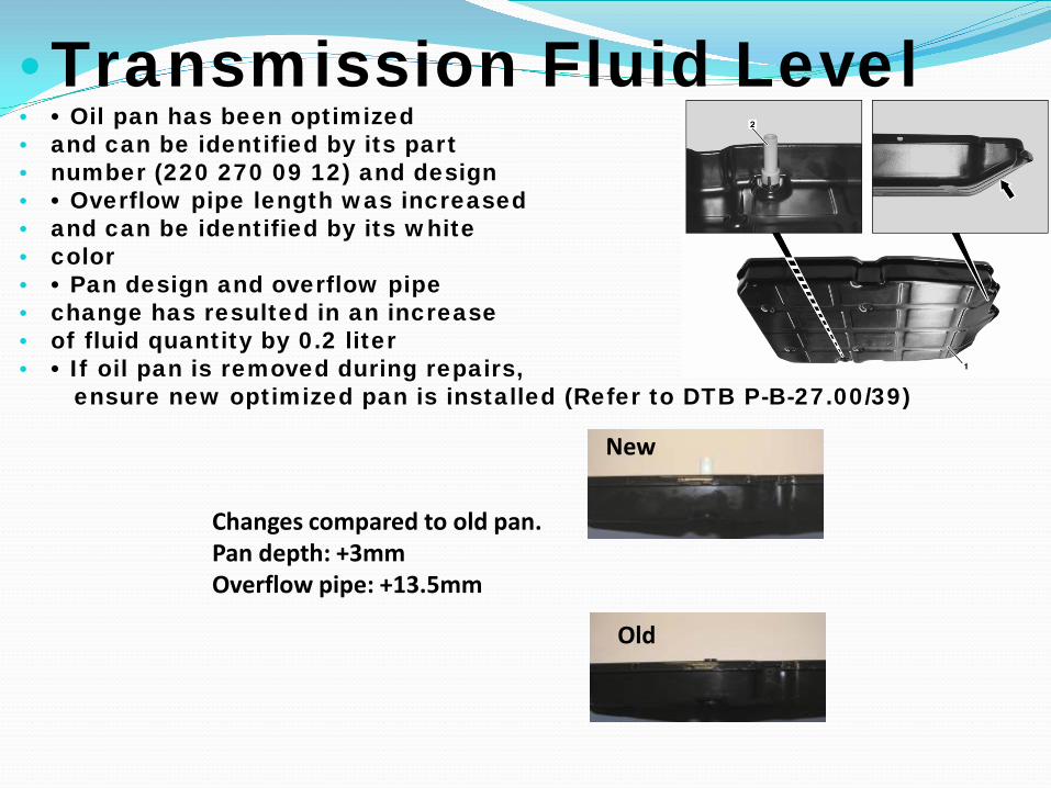
• Transmission Fluid Level • • Oil pan has been optimized • and can be identified by its part • number (220 270 09 12) and design • • Overflow pipe length was increased • and can be identified by its white • color • • Pan design and overflow pipe • change has resulted in an increase • of fluid quantity by 0.2 liter • • If oil pan is removed during repairs, ensure new optimized pan is installed (Refer to DTB P-B-27.00/39)
New
Old
Changes compared to old pan. Pan depth: +3mm Overflow pipe: +13.5mm
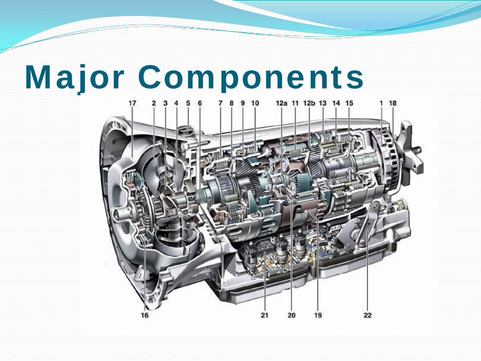
Major Components

Major Components 1. Park pawl gear 2. Turbine wheel 3. Stator 4. Impeller 5. Transmission housing ventilation 6. Oil pump 7. B1 multi-disk brake 8. K1 multi-disk clutch 9. Ravigneaux gear set 10. B3 multi-disk brake 11. K2 multi-disk clutch 12a. Front simple planetary gear set (Also referred to as center gear set) 12b. Rear simple planetary gear set 13. BR multi-disk brake 14. K3 multi-disk clutch 15. B2 multi-disk brake 16. Torque converter lockup clutch 17. Torque converter housing 18. Exciter ring for speed measurement (Output speed) 19. Ring magnet for speed measurement (Internal speed) 20. Ring magnet for speed measurement (Turbine speed) 21. Electro hydraulic control unit 22. Range selector lever

TCC Operation Lock-up torque converter is never fully locked • Converter is open in 1st and 2nd gear if throttle and output shaft speed are in ‘zone A’ • Converter is slip-controlled in all 7 forward gears if throttle and output shaft speed are in ‘zone B’ • Oil supply pressure to converter is varied depending on the amount of slippage - open = high oil flow - slipping = reduced oil flow • Lock-up clutch will be switched off and lower gear selected if oil temperature is too high (>140°C - DTC 2226
A = Open N = output shaft speed B = Slipping D = throttle valve opening

Case • Converter housing is die-cast aluminum • Transmission housing is die-cast magnesium (weight reduction of 2.5 kg compared to aluminum) • Requires aluminum bolts due to: - steel bolts having a different expansion rate - corrosion concerns with steel bolts • Aluminum bolts must be replaced if removed! - No power tools - Adhere to tightening torques & angle • Thread repair to magnesium case is permissible

Case • Bell-housing gasket is made from an aluminum sheet coated with elastomer • Gasket can be reused • Gasket extends out beyond the sealing surfaces to provide a water guard / channel to direct water away from the transmission housing • Gasket ‘lip’ faces forward • Any standing water (especially water containing salt) will corrode magnesium housing over time (e.g. 8 weeks is enough time for salt water to damage housing)

Oil Cooler Lines • Transmission oil cooler connections do not have threads for banjo fitting • Cooler lines are sealed with rubber ‘O’ rings • Oil cooler lines are pushed into connection and secured with retaining bolt

Oil Pump • Crescent type pump (same design as 722.6) Provides necessary oil supply for cooling, lubrication &
hydraulic operations • Suction side of pump has a recess to help reduce oil
intake noise

Apply Components
Note: B1 & B3 multi-disk brakes use single-sided plates

Apply Components
Note: All multi-disk clutches use single-sided plates

Apply Components
• 2 shift members are already applied when transmission is in ‘N’, only one shift member needs to be applied when a drive gear is selected. • A gear change is performed by applying a shift member while disengaging another shift member.

Shift Sequences

Electro-Hydraulics • Basic principle of controlling hydraulics with electronics, as with the 722.6 • Transmission control module will adapt shift for optimal quality • Valve body contains traditional valves, restrictors, selector valve, etc … • Mounted onto valve body are electrical components that control, monitor and enable the gear shifts • Assembly comes as one unit

Electro-Hydraulics
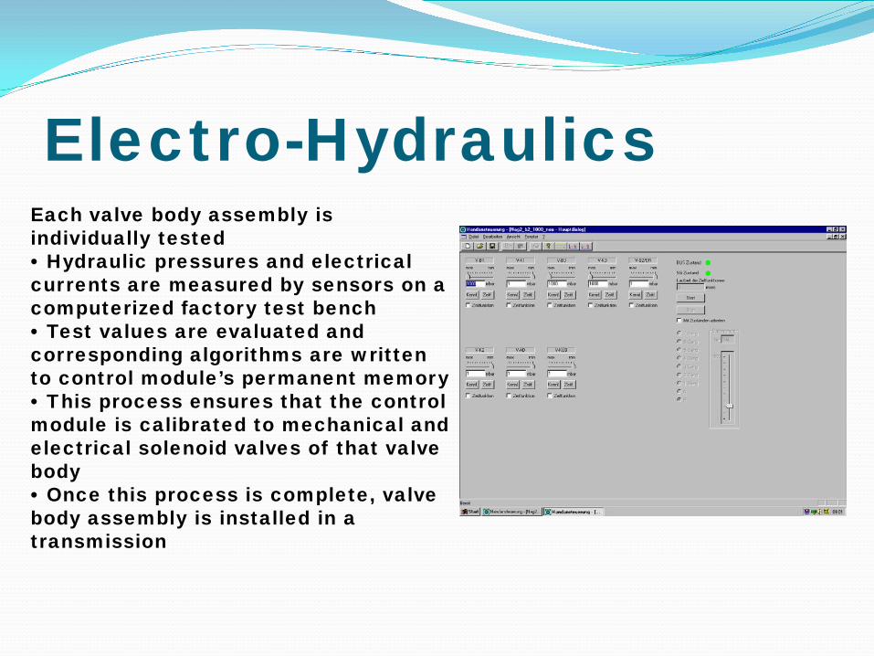
Electro-Hydraulics Each valve body assembly is individually tested • Hydraulic pressures and electrical currents are measured by sensors on a computerized factory test bench • Test values are evaluated and corresponding algorithms are written to control module’s permanent memory • This process ensures that the control module is calibrated to mechanical and electrical solenoid valves of that valve body • Once this process is complete, valve body assembly is installed in a transmission

TCM • TCM - Evaluate various input signals - Calculate shift points according to programming - Evaluate gear shifts & attempt to adapt - Activate eight control solenoid valves • Mounted directly on valve body • Incorporates fluid temperature sensor • Cooled by transmission fluid • Software can be updated (flashable)

TCM Wiring As the control module is integrated into the valve body, wiring to the transmission has been greatly reduced. • Electrical plug connector only has 5 pins: 1 = CAN C High 2 = CAN C Low 3 = to Diagnostic X11/4 according to wiring diagram 4 = circuit 87 (relay & fuse depending on model) 5 = circuit 31 Note: Scan tool communicates with the TCM via CAN C • Plug connector (4e) is sealed by: - 2 round ‘O’ rings (4d) and - 1 square ‘O’ ring (4c) 4c

TCM Communication Information received over CAN C: - Engine rpm - Engine coolant temperature - Throttle pedal position - Engine load - ESP signals - Cruise control signals - ESM (shifter position)
Information received directly: - Speed sensors - Selector range sensor - Transmission fluid temperature

11 Electrical connection X11/4 Diagnostic socket Y3/8n1 Input speed sensor Y3/8n2 Internal speed sensor Y3/8n3 Output speed sensor Y3/8n4 Electric control module Y3/8s1 Selection range sensor Y3/8y_ Solenoid valve
TCM Inputs And Outputs

Speed Sensor • Front speed sensor (Y3/8n1) monitors turbine speed (input shaft / small ring gear) • Center speed sensor (Y3/8n2) monitors Ravigneaux planet carrier speed (ring gear of rear planetary gear set) • These are active speed sensors • Permits signal to be read through other non ferrous parts
Y3/8n1 Turbine rpm sensor Y3/8n2 Internal rpm sensor Y3/8n3 Output rpm sensor

Speed Sensors (Y3/8n1 & n2)

Speed Sensor (Y3/8n3) Output speed sensor measures transmission output speed from ring attached to park pawl gear • Hall effect type sensor • Replaces wheel speed information previously used to calculate shift points and detect gear slip • Direct input to transmission control module
1. Ring magnet 2. Cylinder flange with integrated ring magnet 3. Exciter ring 4a. Park pawl gear
Y3/8n1 Turbine rpm sensor Y3/8n2 Internal rpm sensor Y3/8n3 Output rpm sensor

Range Sensor • Soldered onto ribbon cable of the Transmission control module • Cannot be replaced separately • Records position of selection range lever • Permanent magnetic Linear Contactless Displacement (PLCD) sensor • Construction: - Soft magnetic core surrounded by a wire coil along its length with an additional coil at each end - Permanent magnet on selection range valve, changes magnetic field & output voltage of sensor ** Must be learned ** Signal is compared to ESM
If faulty or not learned = limp-home mode

Fluid Level Sensor • Reduces possibility of gear sets running in fluid (causing ATF foaming) • Two floats are used due to: - Transmission 41 mm longer - ATF sloshes to the front under sharp decel
1 Fluid level float 2 Transmission case

Solenoids Actuated by transmission control module using variable current • Each solenoid valve has a mesh filter beneath it • The following valves produce increasing pressure with increasing current or no pressure with no current (normally closed): - K1 clutch valve (Y3/8y2) - B2 brake valve (Y3/8y6) - B3 brake valve (Y3/8y7) - Torque converter lockup clutch valve (Y3/8y8)

Solenoids • The following valves produce max. pressure with no current or no pressure with max. current (normally open): - Line pressure (Y3/8y1) - K2 clutch valve (Y3/8y3) - K3 clutch valve (Y3/8y4) - B1 brake valve (Y3/8y5) • These valves are responsible for limp-home mode when all valves are de-energized

Diagnostics Oil Level Check Limp-home Modes DTC’s Replacement of Transmission or Control Module SCN & CVN Coding

Fluid Level • Can only be checked at a specific fluid temperature • Currently there are two different oil pan designs with different fluid Temperature and fill specifications: Fluid fill total = 5.2 / 5.4 transmission + 4.0 torque converter + 0.3 cooler circuit • In order to fill or top off the transmission the drain plug must be removed and an adapter screwed on • A special filling station is used to add fluid into transmission via the drain plug Fluid fill total: 9.5 liters early pan, 9.7 liters Late pan Level check: 30 - 35°C early pan, 40 - 45°C Late pan Initial fill check: 30°C 40°C

Limp Home Mode In the event of a transmission failure, the transmission control module has a variety of different limp-home modes that allow vehicle to be driven home or to the nearest shop with limited functionality. • If a shift member solenoid valve is defective, the gear(s) affected is blocked (e.g. Y3/8y7 (B3) defective: no 1st, 7th or Reverse in ‘S’ mode) • If a hydraulic fault prevents a gear from engaging then previous engaged gear is retained • If a computer fault occurs while driving, all control solenoid valves are switched off. The normally open valves would allow full working pressure to go to the respective members - defaults to 6th gear - After shifting to ‘P’, oil pressure from K2 solenoid is redirected to B2 / BR solenoid output circuit via emergency operation valves. - Oil pressure can now be directed to B2 or BR member using selection range valve ‘D’ = 2nd ‘R’ = reverse gear

DTC’s • Transmission control module has over 100 possible fault codes • Only a maximum of 16 fault codes can be stored • If more than 16 fault codes are registered then the 16 fault codes with the highest priority will be stored

Programing • Flashing of the control module should be performed: - after replacing transmission - after replacing electro-hydraulic valve body - to update the control module software to resolve a problem • If transmission control module is new or transmission is replaced, then part of the installation process would be to release transport protection and personalize (marry) the module • Once transmission control module is married to the vehicle, it will not work correctly in another vehicle (only limp-home mode)

Programing • Depending on the scenario some or all of the following will need to be performed after flashing the transmission control module: Ø Determine vehicle data for SCN coding Ø Performing SCN coding - as of MY 2005 performing CVN process in addition to SCN Ø Learning the drive authorization system (required with new module) Ø Teach-in of selection range sensor Tip: Ensure SCN coding is available before programming the control module!

Programing European & American legislation requires that emission relevant control modules be code-able with a Software Calibration Number (SCN)to prevent manipulation of software SCN code will need to be entered after every software update • Failure to enter the SCN code after software update may result in engine not starting

Today’s Presentation Sponsored By:
THANK YOU

[email protected] Questions Survey
Thanks For Attending, See you during our Next ATRA webinar Thanks to our supplier for support