71-mta-1033-r2.1 mt alliance - supermarket …sporlanonline.com/literature/100/mt/71 software...
TRANSCRIPT

M I C R O T H E R M O T E C H N O L O G I E S ™
MT Alliance – Supermarket Control System
Document No. 71-MTA-1033-R2.1 MTA V4.0
No part of this publication may be reproduced, stored in a retrieval system, or transmitted, in any form or by any means, electronic, mechanical, photocopying, recording, or otherwise, without the prior written permission of Micro Thermo Technologies.
© 1997-2015 by Micro Thermo Technologies. All rights reserved worldwide.
Local Phone: (450) 668-3033 | Fax: (450)668-2695 Toll Free Canada: 1-888-664-1406 | Toll Free USA: 1-888-920-6284
www.sporlanonline.com/micro-thermo

71-MTA-1033-R2.1 MT Alliance - Supermarket Control System.doc i
TABLE OF CONTENTS
1 OVERVIEW OF THE MT ALLIANCE SYSTEM ............................................................. 1
1.1 MT ALLIANCE SUB-SYSTEMS ............................................................................................................ 1
2 ARCHITECTURE OF A MT ALLIANCE DISTRIBUTED CONTROL SYSTEMS ...... 6
2.1 PERSONAL COMPUTER ....................................................................................................................... 6 2.2 LONWORKS COMMUNICATIONS NETWORK ................................................................................... 7 2.3 DESCRIPTION AND ROLE OF CONTROLLERS IN THE DIFFERENT MT ALLIANCE SYSTEM
SUB-SYSTEMS ....................................................................................................................................... 8 2.3.1 MT Alliance Monitoring Sub-System .......................................................................................................................... 8 2.3.2 Refrigeration Sub-System .............................................................................................................................................. 9 2.3.3 Heating/Air-Conditioning (HVAC) Sub-System ..................................................................................................... 10 2.3.4 Lighting Sub-System .................................................................................................................................................... 11
3 MT 500 FAMILY ................................................................................................................ 12
3.1 MT 500 FAMILY INPUT-OUTPUT CONFIGURATION .................................................................... 12 3.2 TABLE OF MT ALLIANCE CONTROLLER USING THE 500 FAMILY ............................................. 13
4 DESCRIPTION AND FEATURES OF MICRO THERMO CONTROLLERS ............ 14
4.1 REFRIGERATION SYSTEM CONTROLLERS ...................................................................................... 15 4.1.1 Condenser Controller (MT 504, MT 508 or MT 512) ............................................................................................. 15 4.1.2 Suction Pressure Controller (MT 504) ...................................................................................................................... 16 4.1.3 Compressor Controller ................................................................................................................................................ 17 4.1.4 Refrigeration Circuit Controller.................................................................................................................................. 18 4.1.5 Sub-Cooling System Controller .................................................................................................................................. 19
4.2 HVAC CONTROLLER ....................................................................................................................... 20 4.2.1 Roof-Top Unit Controller (MT 504, MT 508 or MT 512) ..................................................................................... 20 4.2.2 VAV Roof-Top Unit Controller (MT 504, MT 508 or MT 512) ........................................................................... 21 4.2.3 Dual Path (MT 508) Controller .................................................................................................................................. 22
4.3 LIGHTING CONTROLLERS ................................................................................................................ 23 4.3.1 Relay Lighting Controller ............................................................................................................................................ 23 4.3.2 DimLight Controller (MT 504) .................................................................................................................................. 25
APPENDICES ........................................................................................................................ 26
1 INTRODUCTION TO SUPERMARKET REFRIGERATION SYSTEMS ................... 27
1.1 PURPOSE OF A SUPERMARKET REFRIGERATION SYSTEM ........................................................... 27 1.2 OPERATION AND TYPE OF REFRIGERATED CASES ..................................................................... 27 1.3 THERMODYNAMIC PRINCIPLES OF REFRIGERATION .................................................................. 28 1.4 REFRIGERATION SYSTEM COMPONENTS AND FUNCTIONS ........................................................ 29 1.5 REFRIGERATION CYCLE ................................................................................................................... 31 1.6 DEFROSTING CYCLE......................................................................................................................... 32 1.7 HEAT RECLAIM EXCHANGER ......................................................................................................... 32
71-MTA-1033-R2.1 MT Alliance - Supermarket Control System.doc ii
2 INTRODUCTION TO THE SUPERMARKET HVAC SYSTEM ................................. 33
2.1 PURPOSE OF THE HVAC SYSTEM ................................................................................................... 33 2.2 MECHANICAL COMPONENTS OF ROOF-TOP UNITS .................................................................... 34
2.2.1 The table below describes the mechanical components for a roof-top unit and their functions: ..................... 34 2.3 ELECTRONIC COMPONENTS (SENSORS) OF ROOF-TOP UNITS .................................................. 35
2.3.1 The table below describes the electronic components for a roof-top unit and their functions: ....................... 35 2.4 HEATING CYCLE ............................................................................................................................... 35 2.5 DEHUMIDIFICATION CYCLE ............................................................................................................ 36 2.6 AIR-CONDITIONING CYCLE ............................................................................................................ 37
3 INTRODUCTION TO THE LIGHTING SYSTEM ...................................................... 38
3.1 DESCRIPTION OF A LIGHTING CONTROL SYSTEM ....................................................................... 38 3.2 CONFIGURING LIGHTING CONTROLS ........................................................................................... 42 3.3 LIGHTING CONTROL STRATEGY IN THE SUPERMARKET ............................................................ 45
71-MTA-1033-R2.1 MT Alliance - Supermarket Control System.doc 1
1 Overview of the MT Alliance System
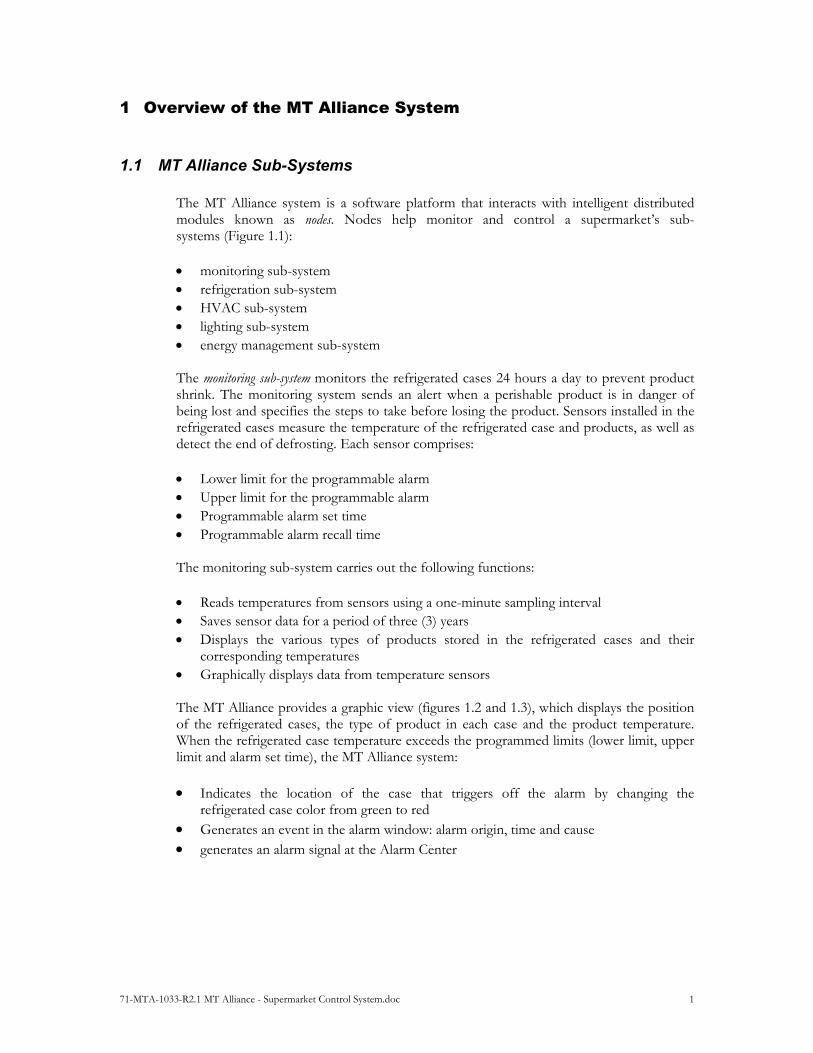
1.1 MT Alliance Sub-Systems The MT Alliance system is a software platform that interacts with intelligent distributed modules known as nodes. Nodes help monitor and control a supermarket’s sub-systems (Figure 1.1): monitoring sub-system refrigeration sub-system HVAC sub-system lighting sub-system energy management sub-system The monitoring sub-system monitors the refrigerated cases 24 hours a day to prevent product shrink. The monitoring system sends an alert when a perishable product is in danger of being lost and specifies the steps to take before losing the product. Sensors installed in the refrigerated cases measure the temperature of the refrigerated case and products, as well as detect the end of defrosting. Each sensor comprises: Lower limit for the programmable alarm Upper limit for the programmable alarm Programmable alarm set time Programmable alarm recall time The monitoring sub-system carries out the following functions: Reads temperatures from sensors using a one-minute sampling interval Saves sensor data for a period of three (3) years Displays the various types of products stored in the refrigerated cases and their
corresponding temperatures Graphically displays data from temperature sensors The MT Alliance provides a graphic view (figures 1.2 and 1.3), which displays the position of the refrigerated cases, the type of product in each case and the product temperature. When the refrigerated case temperature exceeds the programmed limits (lower limit, upper limit and alarm set time), the MT Alliance system: Indicates the location of the case that triggers off the alarm by changing the
refrigerated case color from green to red Generates an event in the alarm window: alarm origin, time and cause generates an alarm signal at the Alarm Center

71-MTA-1033-R2.1 MT Alliance - Supermarket Control System.doc 2
After an alarm has been activated, the user can acknowledge the alarm and take steps to solve the problem. The MT Alliance system provides user names and access codes to each user, which makes it easier to trace the person who acknowledged the alarm. The HVAC sub-system controls HVAC equipment: roof top units, central heating and air-conditioning, zone controllers, etc. With it, users can adjust the temperature and humidity set points in the different areas of a supermarket (Figure 1.4). The lighting sub-system is used to program lighting schedules (Figure 1.5) based on the supermarket’s opening and closing times, as well as on special days such as legal holidays. This sub-system also controls the intensity of supermarket lights based on the surrounding light intensity detected by the photocell sensor.
71-MTA-1033-R2.1 MT Alliance - Supermarket Control System.doc 3
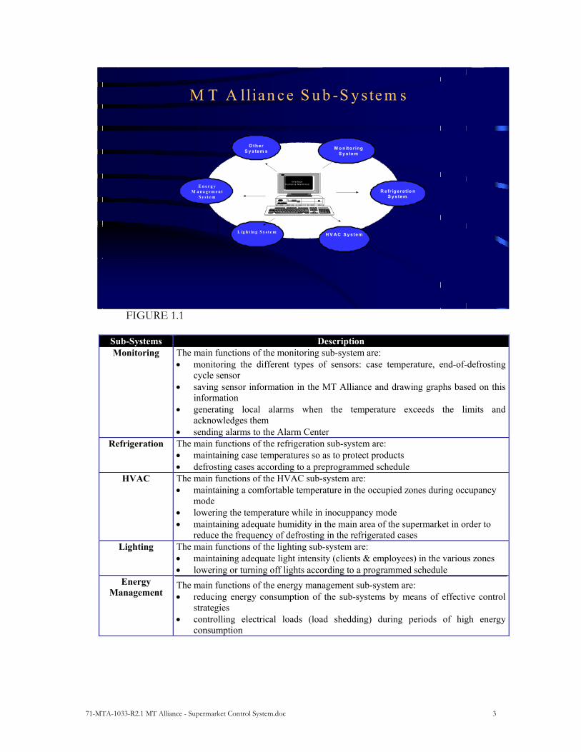
FIGURE 1.1
Sub-Systems Description Monitoring The main functions of the monitoring sub-system are:
monitoring the different types of sensors: case temperature, end-of-defrosting cycle sensor
saving sensor information in the MT Alliance and drawing graphs based on this information
generating local alarms when the temperature exceeds the limits and acknowledges them
sending alarms to the Alarm Center Refrigeration
The main functions of the refrigeration sub-system are: maintaining case temperatures so as to protect products defrosting cases according to a preprogrammed schedule
HVAC
The main functions of the HVAC sub-system are: maintaining a comfortable temperature in the occupied zones during occupancy
mode lowering the temperature while in inocuppancy mode maintaining adequate humidity in the main area of the supermarket in order to
reduce the frequency of defrosting in the refrigerated cases Lighting
The main functions of the lighting sub-system are: maintaining adequate light intensity (clients & employees) in the various zones lowering or turning off lights according to a programmed schedule
Energy Management
The main functions of the energy management sub-system are: reducing energy consumption of the sub-systems by means of effective control
strategies controlling electrical loads (load shedding) during periods of high energy
consumption
M T A llian c e S u b -S y s te m s
R e fr ig e ra t io n S y s tem
L ig h t in g S ys te m
M o nito r ing S y s te m
H V A C S y s tem
Inte r fac eH u m ai ns- M ac h i ne s
O the r S y s te m s
E n e r g y M a na ge m e n t
S ys te m
71-MTA-1033-R2.1 MT Alliance - Supermarket Control System.doc 4
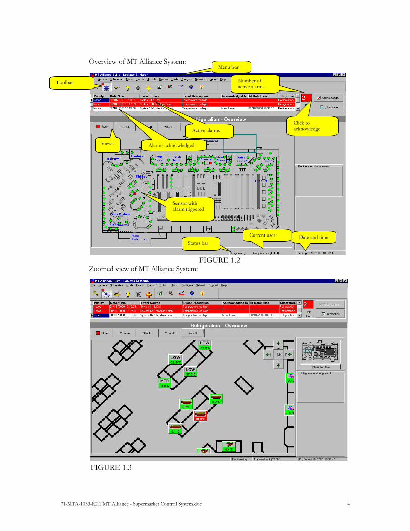
Overview of MT Alliance System:
FIGURE 1.2 Zoomed view of MT Alliance System: FIGURE 1.3
Number of active alarms
Click to acknowledge
Sensor with alarm triggered
Active alarms
Alarms acknowledged Views
Toolbar
Status bar
Menu bar
Date and time Current user

71-MTA-1033-R2.1 MT Alliance - Supermarket Control System.doc 5
View of a window for adjusting temperature:
FIGURE 1.4 View of a lighting schedule:
FIGURE 1.5
1. To select a time range, click and move the mouse
2. Select a light state by clicking "High", “Medium”, ”Low” or “Off”
Days in a typical week
Select a typical week to define the weekly schedule
The time specified will offset the entire schedule accordingly
The blue line represents the setpoint on the graph
Increase or decrease the setpoint or…
… Slide this cursor

71-MTA-1033-R2.1 MT Alliance - Supermarket Control System.doc 6
2 Architecture of a MT Alliance Distributed Control Systems FIGURE 2.1
The distributed control system for a supermarket is made up of the following components: a personal computer a LonWorks communications network electronic modules called nodes or controllers that ensure the operation of the MT
Alliance sub-systems
2.1 Personal Computer The computer allows technicians and users to navigate through the different MT Alliance sub-systems. Therefore, the personal computer is used to carry out the following operations:
Configuring the controllers of the different sub-systems Sending the configuration to the controllers via the LonWorks communications
network Monitoring and controlling the different sub-systems Troubleshooting a technical problem on a sub-system using analysis tools In a distributed system, controlling sub-systems is carried out by the different sub-system controllers and not by the personal computer. Therefore, if the PC crashes, sub-system operation is carried out by the different controllers and the alarms are sent to the Alarm Center. Only data from the sensors, which are normally saved, will be lost if the computer crashes.
Distributed Control System for a Supermarket
RTC
Monitoring Sub-System for Refrigerated Cases
SN26
SN27
SN28
SN63
ALRTRMRefrigeration Sub-System (Rack A)
HVAC Sub-System
Lighting Sub-System
SN 25
1 8
CND SPC CM P1
CM P 2
CKT1
CM P3
CKT2
CKT3
SN29
DPUH
SCHRTU VA V
VA V1
VA V2
ESCH
PTCLCU
1LCU
2LCU
3DIM
5 Circuits
In te rface
User
Legend
TRM : Network Terminat ion
ALR: A larm Controller
RTC : Real T ime C loc k
SN : Sensor N ode
CND: Conde nser Controller
SPC: Suct ion Pressure Controller
CMP: C ompressor Controller
CKT: C ircuit C ontroller
ATS : Anti-Sweat Controller
SCH : Scheduler
DPU: Dua l Path Control
RTU : R oof- top Unit C ontroller
VAV: VAV Box Control
PTC: Photoce ll Sens or
LCU: L ight Control Unit
DIM : D immer Control
Total 64 nodes
500 metres
Sensors
SN30
SNxx
Central alarm system
FTT Network
Re mote communication
PC Anywhe re , Page r, e tc.
VA V3
ATS
71-MTA-1033-R2.1 MT Alliance - Supermarket Control System.doc 7
2.2 LonWorks Communications Network
The LonWorks FTT (free topology) network is made up of a pair of twisted wires that link the controllers to each other without restriction in the controller connection topology. The polarity of the wire pairs can be reversed in the connector to each controller without causing operating problems with the MT Alliance System. To prevent the reflection of signals on the network, the network must have a termination point (end-of-line resistor).
The LonWorks network illustrated in the diagram (Figure 2.1) is limited to 64 nodes and to total length of 500 meters. In certain applications, network capacity can be increased to 124 nodes and to a total length of 1,500 meters, through the addition of two network amplifiers (Repeater).
The communications network has three main functions: Sending computer information (configuration settings, set points) to the controllers Sending controller information (sensor and detector signals, security device and
actuator statuses) to the computer Sending information between controllers
Communications software in the chip of each controller is used to send data between controllers, and between the controllers and PC. The reliability and performance of the sub-systems are assured by the robustness of the communications software. This software re-sends information between controllers and between the controllers and PC following:
A collision in data transmission over the network Unsuccessful data exchange between two controllers on the network

71-MTA-1033-R2.1 MT Alliance - Supermarket Control System.doc 8
2.3 Description and Role of Controllers in the Different MT Alliance System Sub-Systems
2.3.1 MT Alliance Monitoring Sub-System
The table below lists various types of controllers and modules, as well as the main functions of each controller in the Monitoring Sub-System. Refer to the diagram illustrating the Distributed Control System for a Supermarket (Figure 2.1).
Controllers/Node Legend Modules Functions
Sensor Node
SN MT 500 The sensor node is used to monitor eight (8) sensors and generate an alarm if the signal from a sensor exceeds the low or high limit programmed in the node. Different types of sensors can be connected to each input: Temperature sensor for refrigerated cases, temperature sensors for the end of defrosting, refrigerant leak detector, etc.
Real Time Clock
RTC Real Time Clock Normally, the computer’s clock synchronizes with the clock in each controller on the network by regularly sending the time over the network. When the computer crashes, the real-time clock takes over the computer and takes over this function.
Alarm Controller
ALR Alarm Controller When a sensor node generates an alarm, the information is sent to the computer and alarm controllers: The computer displays the alarm in the alarm banner The alarm controller sends the alarm to the Alarm Center
71-MTA-1033-R2.1 MT Alliance - Supermarket Control System.doc 9
2.3.2 Refrigeration Sub-System
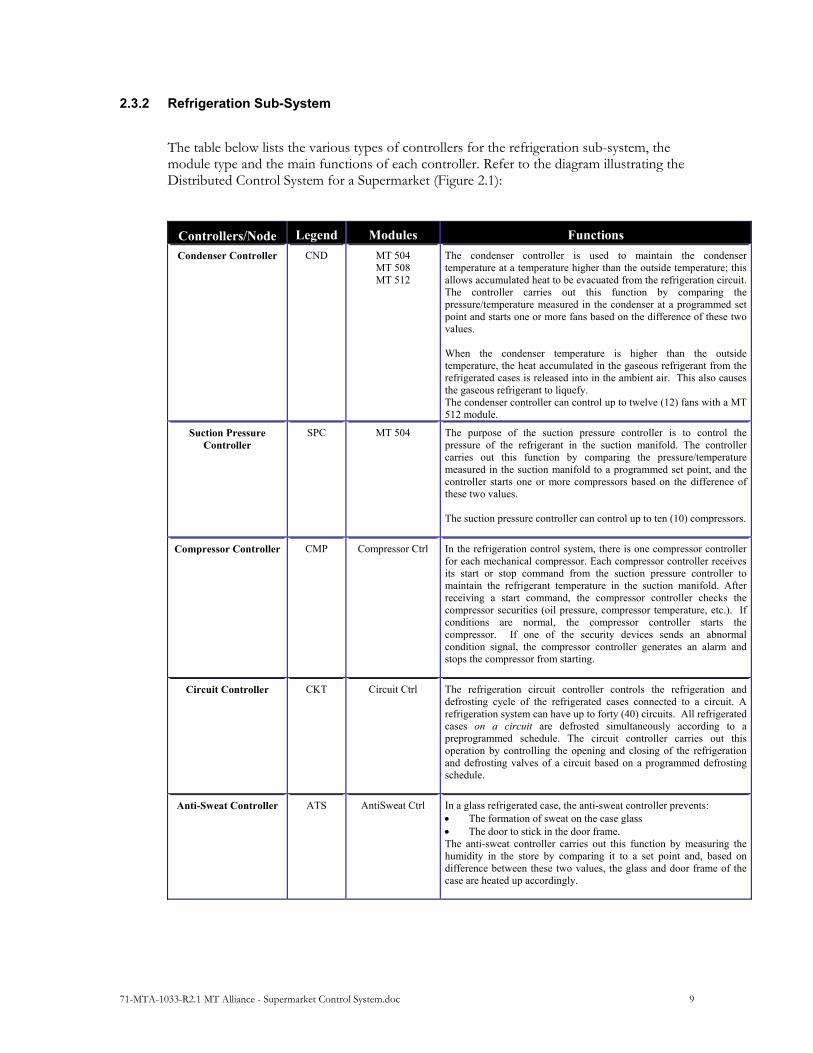
The table below lists the various types of controllers for the refrigeration sub-system, the module type and the main functions of each controller. Refer to the diagram illustrating the Distributed Control System for a Supermarket (Figure 2.1):
ControllersNode Legend Modules Functions
Condenser Controller
CND MT 504 MT 508 MT 512
The condenser controller is used to maintain the condenser temperature at a temperature higher than the outside temperature; this allows accumulated heat to be evacuated from the refrigeration circuit. The controller carries out this function by comparing the pressure/temperature measured in the condenser at a programmed set point and starts one or more fans based on the difference of these two values. When the condenser temperature is higher than the outside temperature, the heat accumulated in the gaseous refrigerant from the refrigerated cases is released into in the ambient air. This also causes the gaseous refrigerant to liquefy. The condenser controller can control up to twelve (12) fans with a MT 512 module.
Suction Pressure Controller
SPC MT 504 The purpose of the suction pressure controller is to control the pressure of the refrigerant in the suction manifold. The controller carries out this function by comparing the pressure/temperature measured in the suction manifold to a programmed set point, and the controller starts one or more compressors based on the difference of these two values. The suction pressure controller can control up to ten (10) compressors.
Compressor Controller
CMP Compressor Ctrl In the refrigeration control system, there is one compressor controller for each mechanical compressor. Each compressor controller receives its start or stop command from the suction pressure controller to maintain the refrigerant temperature in the suction manifold. After receiving a start command, the compressor controller checks the compressor securities (oil pressure, compressor temperature, etc.). If conditions are normal, the compressor controller starts the compressor. If one of the security devices sends an abnormal condition signal, the compressor controller generates an alarm and stops the compressor from starting.
Circuit Controller
CKT Circuit Ctrl The refrigeration circuit controller controls the refrigeration and defrosting cycle of the refrigerated cases connected to a circuit. A refrigeration system can have up to forty (40) circuits. All refrigerated cases on a circuit are defrosted simultaneously according to a preprogrammed schedule. The circuit controller carries out this operation by controlling the opening and closing of the refrigeration and defrosting valves of a circuit based on a programmed defrosting schedule.
Anti-Sweat Controller
ATS
AntiSweat Ctrl In a glass refrigerated case, the anti-sweat controller prevents: The formation of sweat on the case glass The door to stick in the door frame. The anti-sweat controller carries out this function by measuring the humidity in the store by comparing it to a set point and, based on difference between these two values, the glass and door frame of the case are heated up accordingly.

71-MTA-1033-R2.1 MT Alliance - Supermarket Control System.doc 10
2.3.3 Heating/Air-Conditioning (HVAC) Sub-System
The table below lists the various types of controllers for the HVAC sub-system, the type of modules and the main functions of each controller. Refer to the diagram illustrating the Distributed Control System for a Supermarket (Figure 2.1):
ControllersNode Legend Modules Functions
Roof-Top Controller Scheduler
RTU MT 504 MT 508 MT 512
The standard roof-top unit controller controls the main area of a supermarket, i.e., controls temperature controls humidity As well, through the occupation scheduler, it lowers the temperature during unoccupied periods. The type of modules used depends on the number of cooling and heating stages of the roof-top unit.
Dual Path Controller
DPU MT 508 MT 512
The Dual Path Unit is a high energy efficiency air processing unit. The Dual Path controller: controls the temperature of a supermarket Effectively controls humidity (typically 40% to 45%) in the
main area of a supermarket. As well, through the occupation scheduler, it lowers the temperature during unoccupied periods. The type of modules used depends on the number of cooling and heating stages of the Dual Path unit.
VAV Roof -Top Controller
RTUVAV
MT 504 MT 508 MT 512
A VAV roof-top unit and the VAV boxes are used in conjunction to control the temperature of the areas surrounding a supermarket. The VAV roof-top controller controls the air temperature and volume in the main conduit of the unit. The VAV roof-top unit provides constant air pressure at the input of each surrounding area. A VAV roof-top unit can power several VAV boxes. The type of modules used depends on the number of cooling and heating stages connected to the unit.
VAV Box
VAV VAV Ctrl The VAV box is powered by a VAV roof-top unit, which provides air volume at the input of the VAV box. The VAV box controls the temperature of the surrounding areas by varying its dampers. Therefore, the box controls the quantity of air entering the surrounding area and activates electric heating at the end line if required.
HVAC Scheduler
H SCH
Scheduler The scheduler enables the creation of occupied and unoccupied schedules for increasing and decreasing the temperature of a supermarket based on the opening and closing schedule of a supermarket. In addition, schedules can also be created to control the temperatures in different zones based on the occupied and unoccupied periods. A scheduler can control several Dual Path or roof-top units.
71-MTA-1033-R2.1 MT Alliance - Supermarket Control System.doc 11
2.3.4 Lighting Sub-System
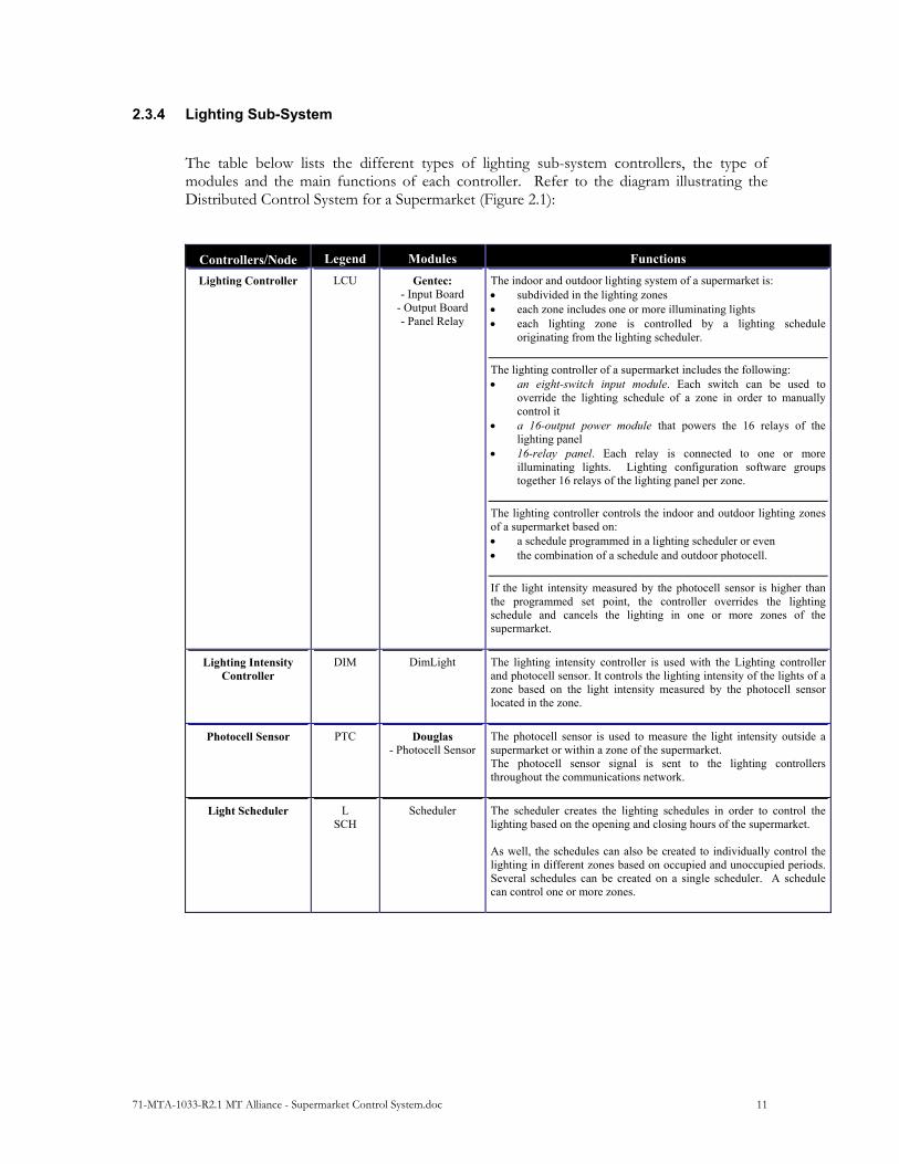
The table below lists the different types of lighting sub-system controllers, the type of modules and the main functions of each controller. Refer to the diagram illustrating the Distributed Control System for a Supermarket (Figure 2.1):
ControllersNode Legend Modules Functions
Lighting Controller
LCU Gentec: - Input Board
- Output Board - Panel Relay
The indoor and outdoor lighting system of a supermarket is: subdivided in the lighting zones each zone includes one or more illuminating lights each lighting zone is controlled by a lighting schedule
originating from the lighting scheduler.
The lighting controller of a supermarket includes the following: an eight-switch input module. Each switch can be used to
override the lighting schedule of a zone in order to manually control it
a 16-output power module that powers the 16 relays of the lighting panel
16-relay panel. Each relay is connected to one or more illuminating lights. Lighting configuration software groups together 16 relays of the lighting panel per zone.
The lighting controller controls the indoor and outdoor lighting zones of a supermarket based on: a schedule programmed in a lighting scheduler or even the combination of a schedule and outdoor photocell.
If the light intensity measured by the photocell sensor is higher than the programmed set point, the controller overrides the lighting schedule and cancels the lighting in one or more zones of the supermarket.
Lighting Intensity Controller
DIM DimLight The lighting intensity controller is used with the Lighting controller and photocell sensor. It controls the lighting intensity of the lights of a zone based on the light intensity measured by the photocell sensor located in the zone.
Photocell Sensor PTC Douglas - Photocell Sensor
The photocell sensor is used to measure the light intensity outside a supermarket or within a zone of the supermarket. The photocell sensor signal is sent to the lighting controllers throughout the communications network.
Light Scheduler
L SCH
Scheduler The scheduler creates the lighting schedules in order to control the lighting based on the opening and closing hours of the supermarket. As well, the schedules can also be created to individually control the lighting in different zones based on occupied and unoccupied periods. Several schedules can be created on a single scheduler. A schedule can control one or more zones.

71-MTA-1033-R2.1 MT Alliance - Supermarket Control System.doc 12
3 MT 500 Family
3.1 MT 500 Family Input-Output Configuration
The MT 500 family is a line of electronic modules developed by Micro Thermo Technologies. The modules in the MT 500 family have a variety of input-output configurations for different supermarket applications. The table below shows the different models of the MT 500 family and their configurations.
M T 5 0 0 F a m i l y I n p u t - O u t p u t C o n f i g u r a t i o n
M T 5 0 0 M T 5 0 4 M T 5 0 8 M T 5 1 2
A n a l o gI n p u t s
8 8 8 8
D i g i t a lI n p u t s
4 8
D i g i t a lO u t p u t s
4 8 1 2
A n a l o g
O u t p u t s4 4 4
TABLE 3.1
71-MTA-1033-R2.1 MT Alliance - Supermarket Control System.doc 13
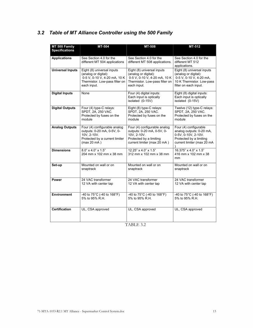
3.2 Table of MT Alliance Controller using the 500 Family
MT 500 Family Specifications
MT-504 MT-508 MT-512
Applications See Section 4.0 for the different MT 504 applications
See Section 4.0 for the different MT 508 applications.
See Section 4.0 for the different MT 512 applications.
Universal Inputs Eight (8) universal inputs (analog or digital): 0-5 V, 0-10 V, 4-20 mA, 10 K Thermistor. Low-pass filter on each input.
Eight (8) universal inputs (analog or digital): 0-5 V, 0-10 V, 4-20 mA, 10 K Thermistor. Low-pass filter on each input.
Eight (8) universal inputs (analog or digital): 0-5 V, 0-10 V, 4-20 mA, 10 K Thermistor. Low-pass filter on each input.
Digital Inputs None Four (4) digital inputs: Each input is optically isolated (0-15V)
Eight (8) digital inputs: Each input is optically isolated (0-15V)
Digital Outputs Four (4) type-C relays: SPDT, 2A, 250 VAC. Protected by fuses on the module
Eight (8) type-C relays: SPDT, 2A, 250 VAC. Protected by fuses on the module
Twelve (12) type-C relays: SPDT, 2A, 250 VAC. Protected by fuses on the module
Analog Outputs Four (4) configurable analog outputs: 0-20 mA, 0-5V, 0-10V, 2-10V. Protected by a current limiter (max 20 mA )
Four (4) configurable analog outputs: 0-20 mA, 0-5V, 0-10V, 2-10V. Protected by a limiting current limiter (max 20 mA )
Four (4) configurable analog outputs: 0-20 mA, 0-5V, 0-10V, 2-10V. Protected by a limiting current limiter (max 20 mA )
Dimensions 8.0” x 4.0” x 1.5” 204 mm x 102 mm x 38 mm
12.25” x 4.0” x 1.5” 312 mm x 102 mm x 38 mm
16.375” x 4.0” x 1.5” 416 mm x 102 mm x 38 mm
Set-up Mounted on wall or on snaptrack
Mounted on wall or on snaptrack
Mounted on wall or on snaptrack
Power 24 VAC transformer 12 VA with center tap
24 VAC transformer 12 VA with center tap
24 VAC transformer 12 VA with center tap
Environment -40 to 75°C (-40 to 168°F) 5% to 95% R.H.
-40 to 75°C (-40 to 168°F) 5% to 95% R.H.
-40 to 75°C (-40 to 168°F) 5% to 95% R.H.
Certification UL, CSA approved
UL, CSA approved
UL, CSA approved
TABLE 3.2

71-MTA-1033-R2.1 MT Alliance - Supermarket Control System.doc 14
4 Description and Features of Micro Thermo Controllers The table below outlines the MT Alliance controllers used in the MT 500 line. In the table, the controllers are grouped by sub-system.
Sub-Systems & Controllers MT 500
MT 504
MT 508
MT 512
Monitoring Sub-System
Sensor Node X
Refrigeration Sub-System
Suction Pressure Controller X
Condenser Controller X
X X
Sub-Cooling Controller X
Secondary Cooling System X
Evaporative Condenser Controller X
HVAC Sub-System
Standard Roof-topController X
X X
VAV Roof-top Controller X
X X
Dual Path Controller (1 Coil) X
Dual Path Controller (2 Coils) X
Lighting Sub-System
Lighting Intensity Controller X
Other Application Controllers
Mechanical Room Controller X
X6T2P Applications Controller X X X
X
X4P4T Applications Controller X X
X X
Table 4.0
71-MTA-1033-R2.1 MT Alliance - Supermarket Control System.doc 15
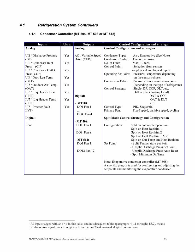
4.1 Refrigeration System Controllers
4.1.1 Condenser Controller (MT 504, MT 508 or MT 512)
Inputs Alarm Outputs Control Configuration and Strategy Analog: UI1 *Discharge Pressure (DP) 1 UI2 *Condenser Inlet Press (CIP) UI3 *Condenser Outlet Press (COP) UI4 *Drop Leg Temp (DLT) UI5 *Outdoor Air Temp (OAT) UI6 * Liq Header Press (LHP) IU7 * Liq Header Temp (LHP) UI8 Inverter Fault IIVF) Digital: None
Yes
Yes
Yes
Yes
Yes
Yes
Yes
Yes
Analog: AO1 Variable Speed Drive (VFD) Digital: - MT504: DO1 Fan 1 … … DO4 Fan 4 - MT 508: DO1 Fan 1 … DO8 Fan 8 - MT 512: DO1 Fan 1 … DO12 Fan 12
Control Configuration and Strategies Condenser Type: Air , Evaporative (See Note) Condenser Config.: One or two rows No. of Fans: Max. 12 fans Control Point: Selection from sensors
on physical and logical inputs. Operating Set Point: Pressure/Temperature depending on the sensors chosen Conversion Table: Pressure/Temperature conversion (depending on the type of refrigerant) Control Strategy: Single: DP, COP, DLT, etc. Differential (floating Head): OAT & COP OAT & DLT etc. Control Type PID, Sequential Primary Fan: Fixed speed, variable speed, cycling Split Mode Control Strategy and Configuration Configuration: Split on outdoor temperature Split on Heat Reclaim 1 Split on Heat Reclaim 2 Split on Heat Reclaim 1 & 2 Split on Out Temp and Heat Reclaim Set Point: - Split Temperature Set Point - Unsplit Discharge Press Set Point - Unsplit Discharge Press Auto Reset - Split Minimum On Time Note: Evaporative condenser controller (MT 508) A specific plug-in is used for configuring and adjusting the set points and monitoring the evaporative condenser.
1 All inputs tagged with an « * » in this table, and in subsequent tables (paragraphs 4.1.1 throught 4.3.2), means that the sensor signal can also originate from the LonWork network (logical connection).
71-MTA-1033-R2.1 MT Alliance - Supermarket Control System.doc 16
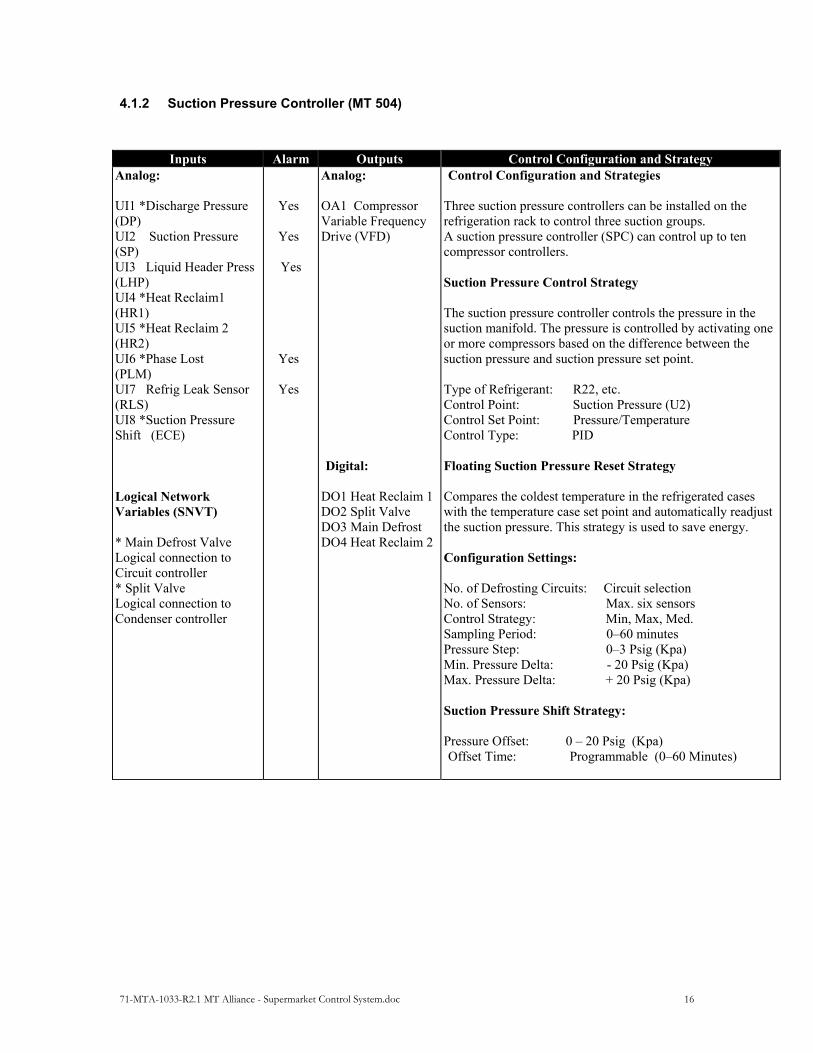
4.1.2 Suction Pressure Controller (MT 504)
Inputs Alarm Outputs Control Configuration and Strategy Analog: UI1 *Discharge Pressure (DP) UI2 Suction Pressure (SP) UI3 Liquid Header Press (LHP) UI4 *Heat Reclaim1 (HR1) UI5 *Heat Reclaim 2 (HR2) UI6 *Phase Lost (PLM) UI7 Refrig Leak Sensor (RLS) UI8 *Suction Pressure Shift (ECE) Logical Network Variables (SNVT) * Main Defrost Valve Logical connection to Circuit controller * Split Valve Logical connection to Condenser controller
Yes
Yes
Yes
Yes
Yes
Analog: OA1 Compressor Variable Frequency Drive (VFD) Digital:
DO1 Heat Reclaim 1 DO2 Split Valve DO3 Main Defrost DO4 Heat Reclaim 2
Control Configuration and Strategies
Three suction pressure controllers can be installed on the refrigeration rack to control three suction groups. A suction pressure controller (SPC) can control up to ten compressor controllers. Suction Pressure Control Strategy The suction pressure controller controls the pressure in the suction manifold. The pressure is controlled by activating one or more compressors based on the difference between the suction pressure and suction pressure set point. Type of Refrigerant: R22, etc. Control Point: Suction Pressure (U2) Control Set Point: Pressure/Temperature Control Type: PID Floating Suction Pressure Reset Strategy Compares the coldest temperature in the refrigerated cases with the temperature case set point and automatically readjust the suction pressure. This strategy is used to save energy. Configuration Settings: No. of Defrosting Circuits: Circuit selection No. of Sensors: Max. six sensors Control Strategy: Min, Max, Med. Sampling Period: 0–60 minutes Pressure Step: 0–3 Psig (Kpa) Min. Pressure Delta: - 20 Psig (Kpa) Max. Pressure Delta: + 20 Psig (Kpa) Suction Pressure Shift Strategy: Pressure Offset: 0 – 20 Psig (Kpa) Offset Time: Programmable (0–60 Minutes)

71-MTA-1033-R2.1 MT Alliance - Supermarket Control System.doc 17
4.1.3 Compressor Controller
Inputs Alarm Outputs Control Configuration and Strategy Analog: - None Digital - Low Pressure Switch - Safety Line - Proof of Running Note: Connector on the
front of the controller.
Yes Yes
Analog: - None Digital: Compressor Cmd Unloader 1 Unloader 2 Note: Optional electronic module is needed for the unloaders control
Control Configuration and Strategies Compressor controllers are controlled by the Suction pressure controller. The pressure is controlled by activating one or more compressors depending on the difference between the suction pressure and the suction pressure set point. An optional module controls the Unloaders. Compressor Controller Configuration Settings - Compressor Type: Recip, Scrool, Screw - Compressor Capacity: hp - Variable Speed Compressor: Yes - Min. Speed: 0–100% - Max. Speed: 0–100% - Option Unloader : Yes - Number of Unloaders: 1–2 - Capacity of Each Unloader: 25% or 33%

71-MTA-1033-R2.1 MT Alliance - Supermarket Control System.doc 18
4.1.4 Refrigeration Circuit Controller
Inputs Alarm Outputs Control Configuration and Strategy Analog: - None Logical Network Variables (SNVT) * Case Temperature * Defrost Termination * Defrost Termination
Switch * Door Ajar
Analog - None Digital . Defr Valve 1 . Refr Valve 1 . Defr Valve 2 . Refr Valve 2 . Defr Valve 3 . Refr Valve 3 . Defr Valve 4 . Refr Valve 4 . Defr Valve 5 . Refr Valve 5
Control Configuration and Strategies The Circuit controller controls five refrigeration circuits. Up to eight (8) circuit controllers can be used on one rack. Thus, 40 refrigeration circuits can be controlled in the rack. Refrigeration Cycle Control: Mode: - Refrig. Valve on/off control - Mechanical EEPR - Electronic EEPR Control Point: Refrigerated case temperature Control Set Point: Desired case temperature Dead Band Set Point: Prevents cycling Defrosting Cycle Control: Defrosting Type: Hot Gas, Off Cycle, Electric Defrost Strategy: On Time, On Temp, Pulse No. Defrostings/Day: 1–8 Max Defrost Time: Programmable Min. Defrost Time: Programmable Circuit Load: Kilo Btu End of Defrosting Sensor: Analog or Digital No. of Sensors: Max. six sensors Defrosting Strategy: Analog: Min, Max, Med. Digital: On state Pump Down Cycle: Pump Down Time Programmable Drain Cycle: Drain Time: Programmable

71-MTA-1033-R2.1 MT Alliance - Supermarket Control System.doc 19
4.1.5 Sub-Cooling System Controller
Inputs Alarm Outputs Control Configuration and Strategy Analog UI1 * Mech Subcooler Temp In (LQT in) UI2 * Mech Subcooler 1 Temp Out (LQTOut 1) UI3 * Mech Subcooler 2 Temp Out(LQTOut2) Digital - None Logical Network Variables (SNVT) - Logical connections to the condenser controller:
* Condenser Saturated Temp * Drop Leg Temp * Outdoor Temp - Logical connection to
the suction pressure controller:
* Suction Pressure
Yes
Yes
Yes
Analog AO1 SPR/CTRL Valve AO2 Receiver Out Valve AO3 Mech Subcooler 1 Valve AO4 Mech Subcooler 2 Valve Digital DO1 Drain Valve DO2 SPR/CTRL Valve DO3 Subcooler 1 Stage 1 DO4 Subcooler 1 Stage 2 DO5 Subcooler 2 Stage 1 DO6 Subcooler 2 Stage 2 DO7 Receiver Out Valve
Control Configuration and Strategies The sub-cooler controller can control different sub-cooling systems: - A condenser sub-cooling system - A mechanical 1 sub-cooling system - A mechanical 2 sub-cooling system The mechanical cooling systems can control two stages. The mechanical sub-cooling system can be configured as an autonomous refrigeration system or dedicated refrigeration circuit. Each sub-cooling sub-system (condenser, mechanical) can be configured to work autonomously or in mixed mode (condenser & mechanical). Mixed mode is very useful in hot climates. - Condenser Sub-Cooling System: - SPR/CTRL Valve Control Control Point: Condenser Saturated Temp (Cop 2 Cot) – Drop Leg Temp Set Point: Desired sub-cooling Control Type: PID Analog Output: -Modulating SPR/CTRL valve - Modulating Receiver Outlet Valve Digital Output: - Selenoid SPR/CTRL valve - Receiver Outlet Valve - Drain Valve Control: Control Point: Suction pressure Set Point: Suction pressure that determines whether at
least one compressor is working Control Type: On/Off control Digital Output: Drain Valve - Mechanical 1 & 2 Sub-Cooling System Configuration: - Autonomous refrigeration system - Dedicated refrigeration circuit Control Point: Mech Subcooler Temp In Set Point: Absolute temperature of liquid Control Type: PID Analog Output: Modulating valve of the mechanical sub-
cooling system Digital Outputs: Stage 1 of mechanical sub-cooling system Stage 2 of mechanical sub-cooling system
71-MTA-1033-R2.1 MT Alliance - Supermarket Control System.doc 20
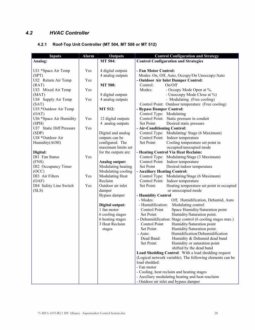
4.2 HVAC Controller
4.2.1 Roof-Top Unit Controller (MT 504, MT 508 or MT 512)
Inputs Alarm Outputs Control Configuration and Strategy
Analog: UI1 *Space Air Temp (SPT) UI2 Return Air Temp (RAT) UI3 Mixed Air Temp (MAT) UI4 Supply Air Temp (SAT) UI5.*Outdoor Air Temp (OAT) UI6 *Space Air Humidity (SPH) UI7 Static Diff Pressure (SDP) UI8 *Outdoor Air Humidity(AOH) Digital: DI1 Fan Status (FNS) DI2 Occupancy Timer (OCC) DI3 Air Filters (OAF) DI4 Safety Line Switch (SLS)
Yes
Yes
Yes
Yes
Yes
Yes
Yes
Yes
Yes
MT 504: 4 digital outputs 4 analog outputs MT 508: 8 digital outputs 4 analog outputs MT 512: 12 digital outputs 4 analog outputs Digital and analog outputs can be configured. The maximum limits set for the outputs are: Analog output: Modulating heating Modulating cooling Modulating Heat Reclaim Outdoor air inlet damper Bypass damper Digital output: 1 fan motor 6 cooling stages 6 heating stages 3 Heat Reclaim stages
Control Configuration and Strategies - Fan Motor Control: Modes: On, Off, Auto, Occupy/On Unoccupy/Auto - Outdoor Air Inlet Damper Control: Control: On/Off Modes: - Occupy Mode Open at %, - Unoccupy Mode Close at %) - Modulating (Free cooling) Control Point: Outdoor temperature (Free cooling) - Bypass Damper Control: Control Type: Modulating Control Point: Static pressure in conduit Set Point: Desired static pressure - Air-Conditioning Control: Control Type: Modulating/ Stage (6 Maximum) Control Point: Indoor temperature Set Point: Cooling temperature set point in occupied/unocupied mode - Heating Control Via Heat Reclaim: Control Type: Modulating/Stage (3 Maximum) Control Point: Indoor temperature Set Point Desired indoor temperature - Auxiliary Heating Control: Control Type: Modulating/Stage (6 Maximum) Control Point: Indoor temperature Set Point: Heating temperature set point in occupied
or unoccupied mode - Humidity Control - Modes: Off, Humidification, Dehumid, Auto - Humidification: Modulating control Control Point Space Humidity/Saturation point Set Point: Humidity/Saturation point. - Dehumidification: Stage control (6 cooling stages max.) Control Point Humidity/Saturation point Set Point: Humidity/Saturation point. - Auto: Humidification/Dehumidification Dead Band: Humidity & Dehumid dead band Set Point: Humidity or saturation point shifted by the dead band Load Shedding Control: With a load shedding request (Logical network variable). The following elements can be load shedded: - Fan motor - Cooling, heat reclaim and heating stages - Auxiliary modulating heating and heat reaclaim - Outdoor air inlet and bypass damper
71-MTA-1033-R2.1 MT Alliance - Supermarket Control System.doc 21
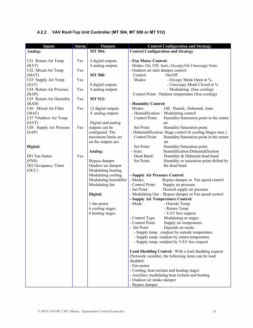
4.2.2 VAV Roof-Top Unit Controller (MT 504, MT 508 or MT 512)
Inputs Alarm Outputs Control Configuration and Strategy Analog: UI1 Return Air Temp (RAT) UI2 Mixed Air Temp (MAT) UI3 Supply Air Temp (SAT) UI4 Return Air Pressure (RAP) UI5 Return Air Humidity (RAH) UI6 Mixed Air Filter (MAF) UI7 *Outdoor Air Temp (OAT) UI8 Supply Air Pressure (SAP) Digital: DI1 Fan Status (FNS) DI2 Occupancy Timer (OCC)
Yes
Yes
Yes
Yes
Yes
Yes
Yes
Yes
MT 504: 4 digital outputs 4 analog outputs MT 508: 8 digital outputs 4 analog outputs MT 512: 12 digital outputs 4 analog outputs Digital and analog outputs can be configured. The maximum limits set on the outputs are: Analog: Bypass damper Outdoor air damper Modulating heating Modulating cooling Modulating humidifierModulating fan Digital: 1 fan motor 6 cooling stages 6 heating stages
Control Configuration and Strategy - Fan Motor Control: Modes: On, Off, Auto, Occupy/On Unoccupy/Auto - Outdoor air inlet damper control: Control: On/Off Modes: - Occupy Mode Open at %, - Unoccupy Mode Closed at % - Modulating (free cooling) Control Point: Outdoor temperature (free cooling) - Humidity Control: Modes: Off, Humid., Dehumid, Auto - Humidification : Modulating control Control Point: Humidity/Saturation point in the return
air Set Point: Humidity/Saturation point. - Dehumidification: Stage control (6 cooling Stages max.) Control Point Humidity/Saturation point in the return
air Set Point: Humidity/Saturation point. - Auto: Humidification/Dehumidification Dead Band: Humidity & Dehumid dead band Set Point: Humidity or saturation point shifted by
the dead band - Supply Air Pressure Control: - Modes: Bypass damper or Fan speed control - Control Point: Supply air pressure - Set Point: Desired supply air pressure - Modulating Out : Bypass damper or Fan speed control - Supply Air Temperature Control: - Mode: - Outside Temp. - Return Temp - VAV box request - Control Type: Modulating or stages - Control Point: Supply air temperature - Set Point Depends on mode: - Supply temp. readjust by outside temperature - Supply temp. readjust by return temperature - Supply temp. readjust by VAV box request Load Shedding Control: With a load shedding request (Network variable), the following items can be load shedded: - Fan motor - Cooling, heat reclaim and heating stages - Auxiliary modulating heat reclaim and heating - Outdoor air intake damper - Bypass damper
71-MTA-1033-R2.1 MT Alliance - Supermarket Control System.doc 22
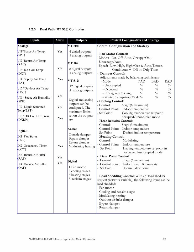
4.2.3 Dual Path (MT 508) Controller
Inputs Alarm Outputs Control Configuration and Strategy
Analog:
UI1*Space Air Temp (SPT)
UI2 Return Air Temp (RAT)
UI3 DX Coil Temp (DXT)
UI4 Supply Air Temp (SAT)
UI5 *Outdoor Air Temp (OAT)
UI6 *Space Air Humidity (SPH)
UI7 Liquid Saturated Temp(LST)
UI8 *DX Coil Diff Press (DXDP)
Digital:
DI1 Fan Status (FNS)
DI2 Occupancy Timer (OCC)
DI3 Return Air Filter (RAF)
DI4 Outside Air Filter (OAF)
Yes
Yes
Yes
Yes
Yes
Yes
Yes
Yes
Yes
MT 504:
4 digital outputs 4 analog outputs
MT 508:
8 digital outputs 4 analog outputs
MT 512:
12 digital outputs 4 analog outputs
Digital and analog outputs can be configured. The maximum limits set on the outputs are:
Analog
Outside damper Bypass damper Return damper Modulating heating
Digital
1 Fan motor 6 cooling stages 6 heating stages 3 reclaim stages
Control Configuration and Strategy - Fan Motor Control: Modes: On, Off, Auto, Occupy/On , Unoccupy/Auto Speed: Low, High, High/Occ & Auto/Unocc, Continuous + Off on Drip Time - Damper Control: Adjustments made by balancing technicians - Mode: OAD BAD RAD - Unoccupied % % % - Occupied % % % - Emergency Cooling % % % - Winter Occupation Mode % % % - Cooling Control: - Control: Stage (6 maximum) - Control Point: Indoor temperature - Set Point: Cooling temperature set point, occupied/unoccupied mode - Heat Reclaim Control: - Control: Stage (3 maximum) - Control Point: Indoor temperature - Set Point: Desired indoor temperature - Heating Control: - Control: Modulating - Control Point: Indoor temperature - Set Point: Heating temperature set point in occupied/unoccupied mode - Dew Point Control: - Control: Stage (6 maximum) - Control Point: Indoor temp. & humidity - Set Point: Desired dew point - Load Shedding Control: With an load shedder request (network variable), the following items can be load shedded: - Fan motor - Cooling and reclaim stages - Modulating heating - Outdoor air inlet damper - Bypass damper - Return damper

71-MTA-1033-R2.1 MT Alliance - Supermarket Control System.doc 23
4.3 Lighting Controllers
4.3.1 Relay Lighting Controller
Inputs Alarm Outputs Control Configuration and Strategy Logical Network
Variables (SNVT)
Analog:
*Lux Level Sensor Digital: - Groups 1 to 6: (Zone) * Occupancy Sensor * Group Override Switch * Occupancy Schedule
-Digital: l6 pulsed relays Analog: - None
Control Configuration and Strategy By configuring the 16 lighting relays in six different groups, relay lighting controller can control six lighting zones.
- Configuration of groups of relays 1 to 6 - Used to assign a relay to a group.
- FOR EACH GROUP. IF THE LIGHT OPERATION TIME EQUALIZATION
OPTION IS ACTIVATED, THE RELAYS FOR A GROUP MAY BE ASSIGNED TO ONE OF THE TWO SUB-GROUPS TO EQUALIZE THE LIGHT OPERATION
TIME OF THE SUB-GROUPS.
- CONTROL OF GROUPS 1–6:
- Light Operation Time Equalization Control for a Group Alternates between the sub-groups of a lighting group
in order to equalize the light operation time - Lighting Control Logic : - Schedule Only - Logical function AND between photocell sensor and schedule - Logical function OR between photocell sensor and schedule - Motion Detector Control
The motion detector can override the lighting schedule for a given period of time. The period of time is programmable.
- Override Control: Override command from a switch, which temporarily
activates a lighting group. The activation time is programmable. - Day/Night Control Specifies day/night status - Control: On/Off - Control Point: Intensity sensor (Lux) - Day/Night Set Point: Value of day/night set point - Set Point Dead Band: Prevents cycling - Day/Night Time: Programmable - load Shedding Control:
- Configuration: A load shedding level from 1 to 4 can be

71-MTA-1033-R2.1 MT Alliance - Supermarket Control System.doc 24
assigned to each lighting relay. Therefore, each relay belongs to a group of load shedding levels 1-4.
- Control: An external load shedding command (Levels 1–4) Load shed a specific group.
71-MTA-1033-R2.1 MT Alliance - Supermarket Control System.doc 25
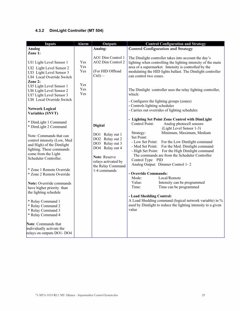
4.3.2 DimLight Controller (MT 504)
Inputs Alarm Outputs Control Configuration and Strategy Analog Zone 1:
UI1 Light Level Sensor 1
UI2 Light Level Sensor 2 UI3 Light Level Sensor 3 UI4 Local Override Switch Zone 2: UI5 Light Level Sensor 1 UI6 Light Level Sensor 2 UI7 Light Level Sensor 3 UI8 Local Override Switch Network Logical Variables (SNVT) * DimLight 1 Command * DimLight 2 Command Note: Commands that can control intensity (Low, Med and High) of the Dimlight lighting. These commands come from the Light Scheduler Controller.
* Zone 1 Remote Override * Zone 2 Remote Override Note: Overrride commands have higher priority than the lighting schedule * Relay Command 1 * Relay Command 2 * Relay Command 3 * Relay Command 4
Note: Commands that individually activate the relays on outputs DO1- DO4
Yes Yes Yes
Yes Yes Yes
Analog: AO1 Dim Control 1 AO2 Dim Control 2 (For HID Offload Ctrl)––
Digital DO1 Relay out 1 DO2 Relay out 2 DO3 Relay out 3 DO4 Relay out 4 Note: Reserve relays activated by the Relay Command 1-4 commands
Control Configuration and Strategy The Dimlight controller takes into account the day’s lighting when controlling the lighting intensity of the main area of a supermarket. Intensity is controlled by the modulating the HID lights ballast. The Dimlight controller can control two zones.
The Dimlight controller uses the relay lighting controller, which:
- Configures the lighting groups (zones) - Controls lighting schedules - Carries out overrides of lighting schedules - Lighting Set Point Zone Control with DimLight Control Point: Analog photocell sensors (Light Level Sensor 1-3) Strategy: Minimum, Maximum, Medium Set Point: - Low Set Point: For the Low Dimlight command - Med Set Point: For the Med. Dimlight command - High Set Point: For the High Dimlight command The commands are from the Scheduler Controller Control Type PID Analog Output: Dimmer Control 1- 2
- - Override Commands: Mode: Local/Remote Value: Intensity can be programmed Time: Time can be programmed - Load Shedding Control: A Load Shedding command (logical network variable) in % used by Dimlight to reduce the lighting intensity to a given value

71-MTA-1033-R2.1 MT Alliance - Supermarket Control System.doc 26
Appendices
71-MTA-1033-R2.1 MT Alliance - Supermarket Control System.doc 27
1 Introduction to Supermarket Refrigeration Systems
1.1 Purpose of a Supermarket Refrigeration System A supermarket refrigeration system has two main functions:
to refrigerate cold storage rooms used to store products before they are transferred to the refrigerated cases;
to maintain an optimal temperature in cold storage rooms and refrigerated cases in order to conserve products.
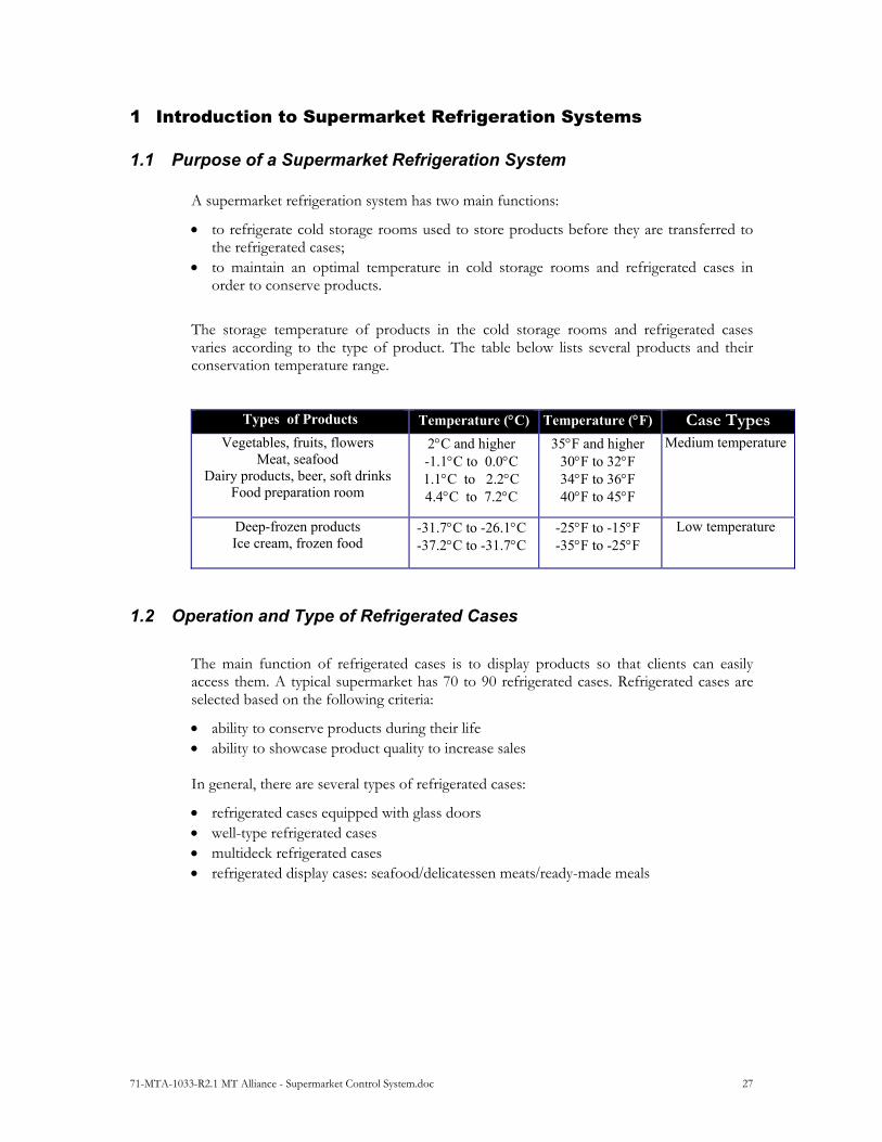
The storage temperature of products in the cold storage rooms and refrigerated cases varies according to the type of product. The table below lists several products and their conservation temperature range.
Types of Products Temperature (C) Temperature (F) Case Types Vegetables, fruits, flowers
Meat, seafood Dairy products, beer, soft drinks
Food preparation room
2C and higher -1.1C to 0.0C 1.1C to 2.2C 4.4C to 7.2C
35F and higher 30F to 32F 34F to 36F 40F to 45F
Medium temperature
Deep-frozen products Ice cream, frozen food
-31.7C to -26.1C -37.2C to -31.7C
-25F to -15F -35F to -25F
Low temperature
1.2 Operation and Type of Refrigerated Cases
The main function of refrigerated cases is to display products so that clients can easily access them. A typical supermarket has 70 to 90 refrigerated cases. Refrigerated cases are selected based on the following criteria:
ability to conserve products during their life ability to showcase product quality to increase sales In general, there are several types of refrigerated cases:
refrigerated cases equipped with glass doors well-type refrigerated cases multideck refrigerated cases refrigerated display cases: seafooddelicatessen meatsready-made meals
71-MTA-1033-R2.1 MT Alliance - Supermarket Control System.doc 28
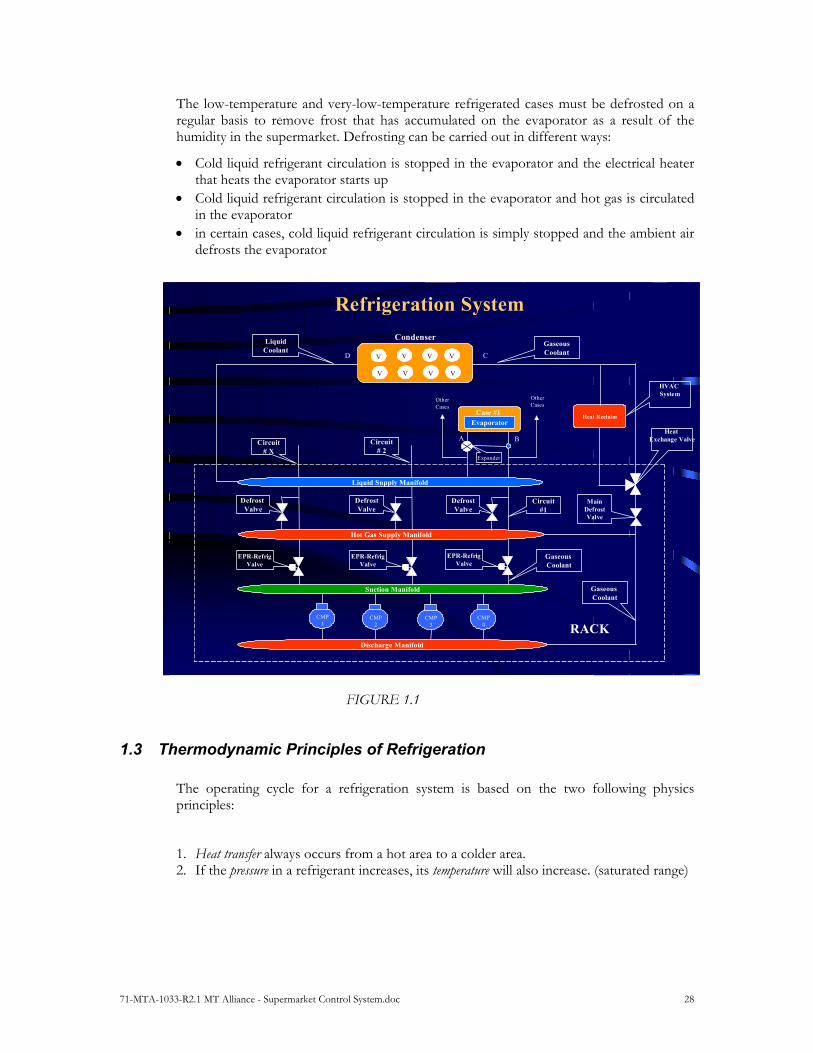
The low-temperature and very-low-temperature refrigerated cases must be defrosted on a regular basis to remove frost that has accumulated on the evaporator as a result of the humidity in the supermarket. Defrosting can be carried out in different ways:
Cold liquid refrigerant circulation is stopped in the evaporator and the electrical heater that heats the evaporator starts up
Cold liquid refrigerant circulation is stopped in the evaporator and hot gas is circulated in the evaporator
in certain cases, cold liquid refrigerant circulation is simply stopped and the ambient air defrosts the evaporator
FIGURE 1.1
1.3 Thermodynamic Principles of Refrigeration The operating cycle for a refrigeration system is based on the two following physics principles:
1. Heat transfer always occurs from a hot area to a colder area. 2. If the pressure in a refrigerant increases, its temperature will also increase. (saturated range)
CMP 1
CMP 2
CMP 3
CMP 4
Refrigeration System
V
V
V
V
V
V
V
V
Condenser
Suction Manifold
Hot Gas Supply Manifold
Discharge Manifold
Evaporator
Case #1
Other Cases
Circuit#1
Other Cases
Circuit# 2
Circuit# X
Heat Reclaim
Liquid Supply Manifold
Gaseous Coolant
GaseousCoolant
LiquidCoolant
Gaseous Coolant
EPR-RefrigValve
EPR-RefrigValve
EPR-RefrigValve
DefrostValve
DefrostValve
Defrost Valve
MainDefrostValve
Heat Exchange Valve
RACK
A
CD
Expander
HVAC System
B
71-MTA-1033-R2.1 MT Alliance - Supermarket Control System.doc 29
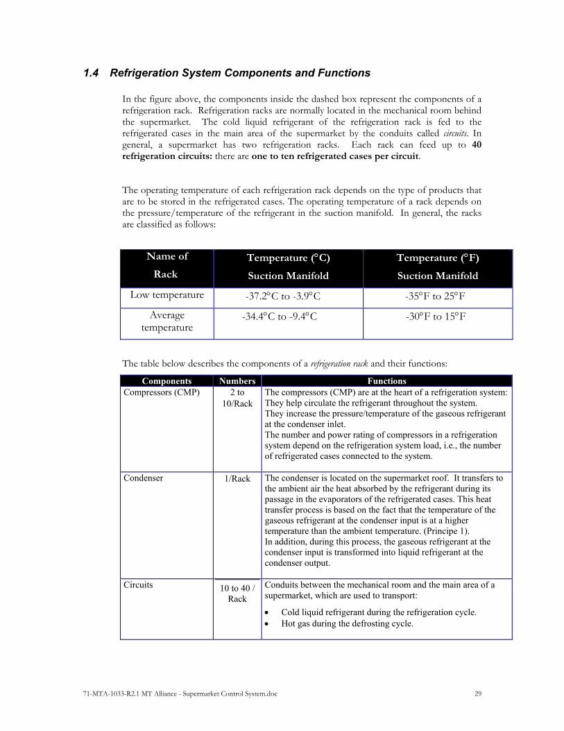
1.4 Refrigeration System Components and Functions In the figure above, the components inside the dashed box represent the components of a refrigeration rack. Refrigeration racks are normally located in the mechanical room behind the supermarket. The cold liquid refrigerant of the refrigeration rack is fed to the refrigerated cases in the main area of the supermarket by the conduits called circuits. In general, a supermarket has two refrigeration racks. Each rack can feed up to 40 refrigeration circuits: there are one to ten refrigerated cases per circuit.
The operating temperature of each refrigeration rack depends on the type of products that are to be stored in the refrigerated cases. The operating temperature of a rack depends on the pressure/temperature of the refrigerant in the suction manifold. In general, the racks are classified as follows:
Name of
Rack
Temperature (C)
Suction Manifold
Temperature (F)
Suction Manifold
Low temperature -37.2C to -3.9CF -35F to 25FF
Average temperature
-34.4C to -9.4C -30F to 15F
The table below describes the components of a refrigeration rack and their functions:
Components Numbers Functions Compressors (CMP) 2 to
10Rack The compressors (CMP) are at the heart of a refrigeration system:They help circulate the refrigerant throughout the system. They increase the pressure/temperature of the gaseous refrigerant at the condenser inlet. The number and power rating of compressors in a refrigeration system depend on the refrigeration system load, i.e., the number of refrigerated cases connected to the system.
Condenser 1Rack The condenser is located on the supermarket roof. It transfers to the ambient air the heat absorbed by the refrigerant during its passage in the evaporators of the refrigerated cases. This heat transfer process is based on the fact that the temperature of the gaseous refrigerant at the condenser input is at a higher temperature than the ambient temperature. (Principe 1). In addition, during this process, the gaseous refrigerant at the condenser input is transformed into liquid refrigerant at the condenser output.
Circuits 10 to 40 / Rack
Conduits between the mechanical room and the main area of a supermarket, which are used to transport:
Cold liquid refrigerant during the refrigeration cycle. Hot gas during the defrosting cycle.

71-MTA-1033-R2.1 MT Alliance - Supermarket Control System.doc 30
Components Numbers Functions Defrost Valve 1Circuit During the defrosting cycle:
The defrost valve is open and allows hot gas from the hot gas supply manifold flow into the circuit to defrost the refrigerated cases.
The refrigeration valve is closed. The frequency for defrosting a circuit is based on a programmed schedule. The defrosting schedule is programmed so that one or two circuits are defrosted simultaneously depending on the load of each circuit (number of refrigerated cases on the circuit and their temperature.
Refrigeration Valve 1Circuit During the refrigeration cycle: The refrigeration valve is open and lets cold liquid circulate
in cases connected to the circuit. The defrost valve is closed.
EPR Valve 1Circuit The EPR valve is used to adjust the refrigerated cases temperature (evaporators) connected to a circuit.
Main Defrost Valve 1Rack The main defrost valve is opened during hot gas defrosting in one of the circuits. Opening the valve creates differential pressure, which lets hot gas circulate in the defrost circuit(s).
Hear Reclaim Valve 1Rack When this valve has been activated, the warm gas from the discharge flows through the heat reclaim system located in the main conduit of the HVAC system. This heats the air circulating in the main conduit of the HVAC system. This valve is activated following a heating or dehumidifier request from the HVAC control system.
Suction Manifold 1Rack During the refrigeration cycle, the suction manifold receives, via each circuit, the gaseous refrigerant from the refrigerated cases. The suction manifold is used to supply the compressors with refrigerant.
Discharge Manifold 1Rack The discharge manifold is connected to the compressor discharge. The compressors compress the gas refrigerant in the discharge manifold at a very high pressure/temperature.
Liquid Supply Manifold
1Rack The liquid supply manifold receives the liquid refrigerant from the condenser. The liquid supply manifold is used to supply the refrigerated cases by cooling the liquid in order to lower the temperatures of the refrigerated cases.
Hot Gas Manifold 1Rack The hot gas manifold is fed by the compressor discharge manifold. During a defrosting cycle, the defrost valve is open and supplies the defrost circuit with hot gas to defrost the refrigerated cases.
71-MTA-1033-R2.1 MT Alliance - Supermarket Control System.doc 31
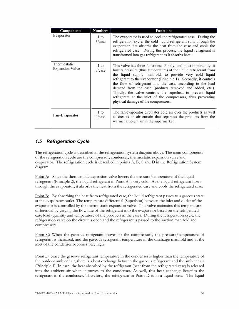
Components Numbers Functions Evaporator 1 to
3case The evaporator is used to cool the refrigerated case. During the refrigeration cycle, the cold liquid refrigerant runs through the evaporator that absorbs the heat from the case and cools the refrigerated case. During this process, the liquid refrigerant is transformed into gas refrigerant as it absorbs heat.
Thermostatic Expansion Valve
1 to 3case
This valve has three functions: Firstly, and most importantly, it lowers pressure (thus temperature) of the liquid refrigerant from the liquid supply manifold, to provide very cold liquid refrigerant to the evaporator (Principle 1). Secondly, it controls the flow of refrigerant into the case, according to the load demand from the case (products removed and added, etc.). Thirdly, the valve controls the superheat to prevent liquid refrigerant at the inlet of the compressors, thus preventing physical damage of the compressors.
Fan–Evaporator
1 to 3case
The fan/evaporator circulates cold air over the products as well as creates an air curtain that separates the products from the warmer ambient air in the supermarket.
1.5 Refrigeration Cycle
The refrigeration cycle is described in the refrigeration system diagram above. The main components of the refrigeration cycle are the compressor, condenser, thermostatic expansion valve and evaporator. The refrigeration cycle is described in points A, B, C and D in the Refrigeration System diagram. Point A: Since the thermostatic expansion valve lowers the pressure/temperature of the liquid refrigerant (Principle 2), the liquid refrigerant in Point A is very cold. As the liquid refrigerant flows through the evaporator, it absorbs the heat from the refrigerated case and cools the refrigerated case. Point B: By absorbing the heat from refrigerated case, the liquid refrigerant passes to a gaseous state at the evaporator outlet. The temperature differential (Superheat) between the inlet and outlet of the evaporator is controlled by the thermostatic expansion valve. This valve maintains this temperature differential by varying the flow rate of the refrigerant into the evaporator based on the refrigerated case load (quantity and temperature of the products in the case). During the refrigeration cycle, the refrigeration valve on the circuit is open and the refrigerant is passed to the suction manifold and compressors. Point C: When the gaseous refrigerant moves to the compressors, the pressure/temperature of refrigerant is increased, and the gaseous refrigerant temperature in the discharge manifold and at the inlet of the condenser becomes very high.
Point D: Since the gaseous refrigerant temperature in the condenser is higher than the temperature of the outdoor ambient air, there is a heat exchange between the gaseous refrigerant and the ambient air (Principle 1). In turn, the heat absorbed by the refrigerant (heat from the refrigerated case) is released into the ambient air when it moves to the condenser. As well, this heat exchange liquefies the refrigerant in the condenser. Therefore, the refrigerant in Point D is in a liquid state. The liquid

71-MTA-1033-R2.1 MT Alliance - Supermarket Control System.doc 32
refrigerant at the outlet of the condenser is passed to the liquid supply manifold and to the thermostatic expansion valve and the refrigeration cycle starts all over again.
1.6 Defrosting Cycle
During the defrosting cycle, a circuit defrost valve is open and the circuit’s EPR-Refrigeration valve is closed. The hot gas refrigerant in the defrost supply manifold from the compressor defrost manifold is circulated into the refrigerated case evaporators of the defrost circuit; this operation defrosts the evaporators. Since the evaporators are very cold, the gaseous refrigerant becomes liquid and sent to the liquid supply manifold.
1.7 Heat Reclaim Exchanger
The heat reclaim unit is located in the main conduit of the HVAC system. Following a heat or dehumidification request, a signal is sent from the HVAC controller to the Suction pressure controller. The Suction pressure controller opens the heat reclaim valve, enabling the hot gas refrigerant in the discharge manifold to pass through the heat reclaim valve. This, in turn, heats the air circulating in the main conduit of the HVAC system.
71-MTA-1033-R2.1 MT Alliance - Supermarket Control System.doc 33
2 Introduction to the Supermarket HVAC System
2.1 Purpose of the HVAC System
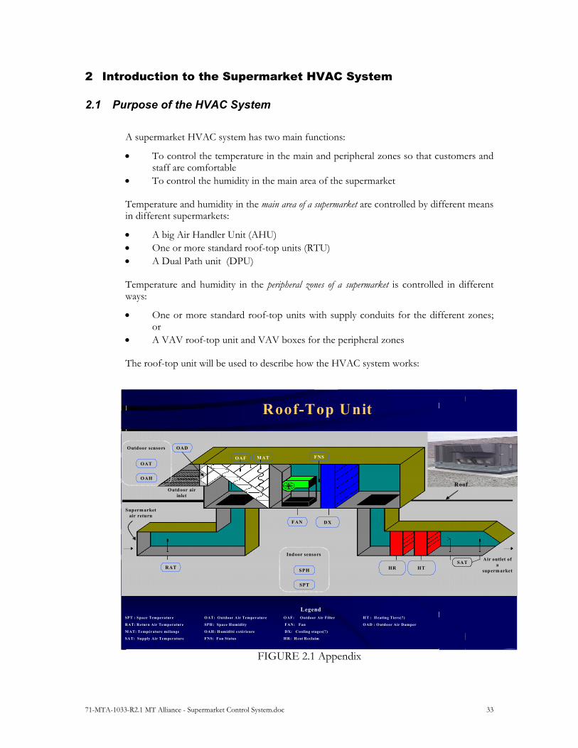
A supermarket HVAC system has two main functions:
To control the temperature in the main and peripheral zones so that customers and staff are comfortable
To control the humidity in the main area of the supermarket Temperature and humidity in the main area of a supermarket are controlled by different means in different supermarkets:
A big Air Handler Unit (AHU) One or more standard roof-top units (RTU) A Dual Path unit (DPU) Temperature and humidity in the peripheral zones of a supermarket is controlled in different ways:
One or more standard roof-top units with supply conduits for the different zones; or
A VAV roof-top unit and VAV boxes for the peripheral zones The roof-top unit will be used to describe how the HVAC system works:
FIGURE 2.1 Appendix
Roof-Top Unit
RAT
OAF MAT
OAD
FAN DX
HR HT
Roof
Air outlet of a
superm arket
Outdoor air inlet
LegendSPT : Space Temperature OAT: Outdoor Air Temperature O AF: Outdoor Air Filter H T : H eating Tiers(?)
RAT: Return Air Te mperature SPH: Space H umidity FAN: Fan O AD : O utdoor Air Damper
M AT: Te mpérature mélange OAH: H umidité extérieure DX: Cooling stages(?)
SA T: Supply Air Temperature FNS: Fan Status H R: H eat Reclaim
SAT
SPT
SPH
Indoor sensors
FNS
Supermarket air return
OAH
OAT
Outdoor sensors
71-MTA-1033-R2.1 MT Alliance - Supermarket Control System.doc 34
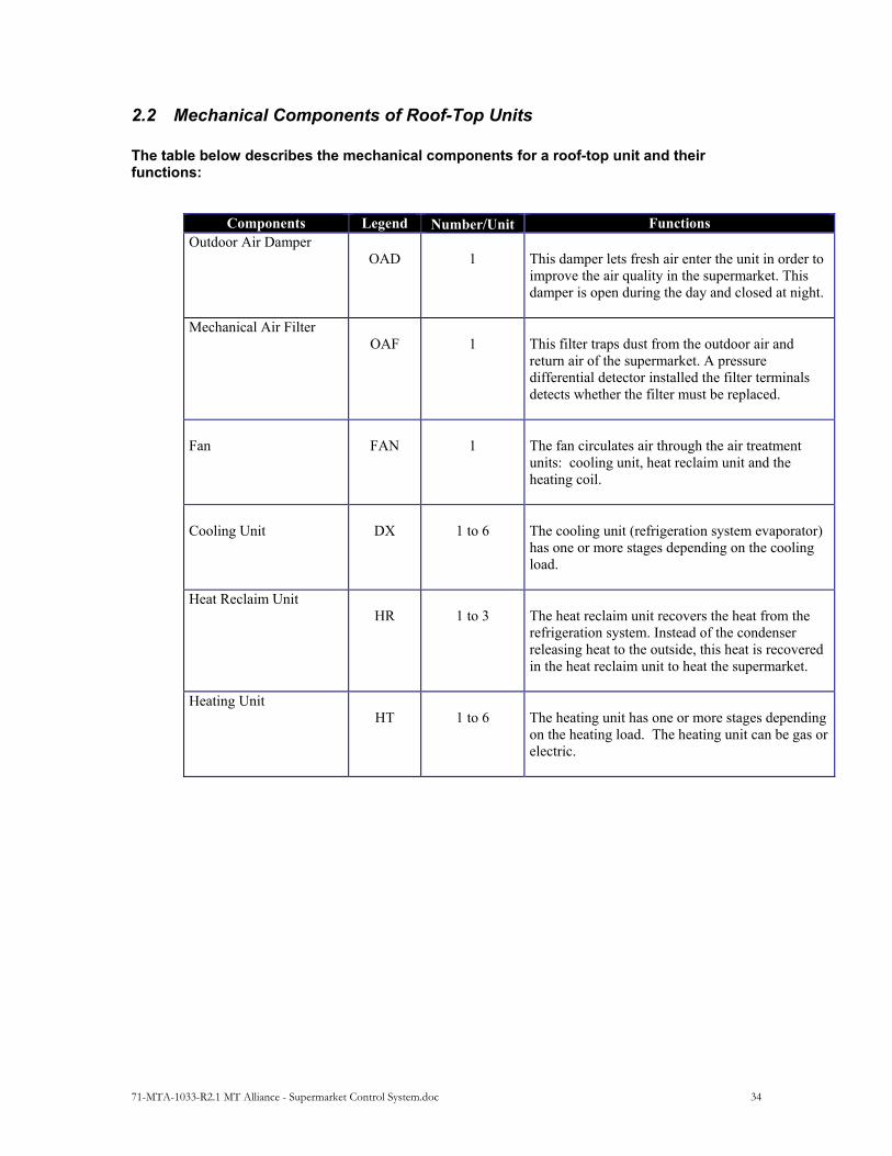
2.2 Mechanical Components of Roof-Top Units
The table below describes the mechanical components for a roof-top unit and their functions:
Components Legend NumberUnit Functions Outdoor Air Damper
OAD
1
This damper lets fresh air enter the unit in order to improve the air quality in the supermarket. This damper is open during the day and closed at night.
Mechanical Air Filter
OAF
1
This filter traps dust from the outdoor air and return air of the supermarket. A pressure differential detector installed the filter terminals detects whether the filter must be replaced.
Fan
FAN
1
The fan circulates air through the air treatment units: cooling unit, heat reclaim unit and the heating coil.
Cooling Unit
DX
1 to 6
The cooling unit (refrigeration system evaporator) has one or more stages depending on the cooling load.
Heat Reclaim Unit
HR
1 to 3
The heat reclaim unit recovers the heat from the refrigeration system. Instead of the condenser releasing heat to the outside, this heat is recovered in the heat reclaim unit to heat the supermarket.
Heating Unit
HT
1 to 6
The heating unit has one or more stages depending on the heating load. The heating unit can be gas or electric.
71-MTA-1033-R2.1 MT Alliance - Supermarket Control System.doc 35
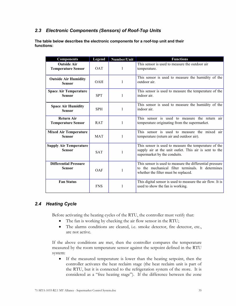
2.3 Electronic Components (Sensors) of Roof-Top Units
The table below describes the electronic components for a roof-top unit and their functions:
Components Legend NumberUnit Functions Outside Air
Temperature Sensor OAT 1 This sensor is used to measure the outdoor air temperature.
Outside Air Humidity Sensor OAH 1
This sensor is used to measure the humidity of the outdoor air.
Space Air Temperature Sensor SPT 1
This sensor is used to measure the temperature of the indoor air.
Space Air Humidity Sensor SPH 1
This sensor is used to measure the humidity of the indoor air.
Return Air Temperature Sensor RAT 1
This sensor is used to measure the return air temperature originating from the supermarket.
Mixed Air Temperature Sensor MAT 1
This sensor is used to measure the mixed air temperature (return air and outdoor air).
Supply Air Temperature Sensor
SAT 1
This sensor is used to measure the temperature of the supply air at the unit outlet. This air is sent to the supermarket by the conduits.
Differential Pressure Sensor
OAF 1
This sensor is used to measure the differential pressure to the mechanical filter terminals. It determines whether the filter must be replaced.
Fan Status FNS 1
This digital sensor is used to measure the air flow. It is used to show the fan is working.
2.4 Heating Cycle
Before activating the heating cycles of the RTU, the controller must verify that: The fan is working by checking the air flow sensor in the RTU; The alarms conditions are cleared, i.e. smoke detector, fire detector, etc.,
are not active. If the above conditions are met, then the controller compares the temperature measured by the room temperature sensor against the setpoint defined in the RTU system:
If the measured temperature is lower than the heating setpoint, then the controller activates the heat reclaim stage (the heat reclaim unit is part of the RTU, but it is connected to the refrigeration system of the store. It is considered as a “free heating stage”). If the difference between the zone
71-MTA-1033-R2.1 MT Alliance - Supermarket Control System.doc 36
temperature and the setpoint is still high, and if it is impossible to reach the setpoint value with the heat reclaim stage only, then the controller will gradually activate one or more heating stages (electrical or gas) until the setpoint is reached;
If the measured temperature is greater than the heating setpoint, then the controller will gradually shutdown the electrical (or gas) heating stages until the setpoint is reached. If the room temperature is still too high, the controller will shutdown the heat reclaim unit.
2.5 Dehumidification Cycle The humidity in the main area of a supermarket is a major concern. If the humidity in the building is not controlled efficiently, frost will build up on the refrigerated food display cases’ evaporators, thus resulting in an increase of the frequency of the defrost cycles. This leads to disastrous effects:
Increase of energy consumption; Deterioration of food quality in the refrigerated cases.
Before the dehumidifier cycle is activated, the controller must verify that:
The fan is on by checking the air flow sensor in the RTU; All alarms conditions are cleared, i.e. excessively low temperature in the
cooling coil, fire detector, etc., are not active. If the above conditions are met, then the controller compares the humidity measured by the room temperature sensor against the setpoint defined in the RTU system:
If the measured humidity is higher than the humidity setpoint, then the controller activates the first stage of cooling. If the difference between the measured humidity and the setpoint is still high, and if it is impossible to reach the setpoint value with the first stage of cooling only, then the controller will gradually activate one or more cooling stages until the setpoint is reached. During this cycle, the water contained in the air will condense at the contact of the cooling coils and will be recuperated in a drain pan2;
If the measured humidity is lower than the humidity setpoint, then the controller will gradually shutdown the cooling stages until the setpoint is reached.
2 The dehumidification cycle cools the air in the main area of the supermarket and could cause discomfort to customers. Therefore, as soon as the measured temperature goes below the temperature setpoint, the controller activates the heat reclaim stage to compensate. Other heating stages can be activated as well, as described in section Error! Reference source not found. Error! Reference source not found., on page Error! Bookmark not defined.. The dehumidification cycle and the heating cycle are independent from one to the other.

71-MTA-1033-R2.1 MT Alliance - Supermarket Control System.doc 37
2.6 Air-Conditioning Cycle The peripheral zones of a supermarket (offices, rest areas, bathrooms, etc.) could be, from time to time, air conditioned for the employees comfort. Before the cooling cycle is activated, the controller must verify that:
The fan is on by checking the air flow sensor in the RTU; All alarms conditions are cleared, i.e. excessively low temperature in the
cooling coil, fire detector, etc., are not active. If the above conditions are met, then the controller compares the temperature measured by the room temperature sensor against the setpoint defined in the RTU system:
If the measured temperature is greater than the cooling setpoint, then the controller activates the first stage of cooling. If the difference between the measured temperature and the setpoint is still high, and if it is impossible to reach the setpoint value with the first stage of cooling only, then the controller will gradually activate one or more cooling stages until the setpoint is reached;
If the measured temperature is lower than the cooling setpoint, then the controller will gradually shutdown the cooling stages until the setpoint is reached.
71-MTA-1033-R2.1 MT Alliance - Supermarket Control System.doc 38
3 Introduction to the Lighting System
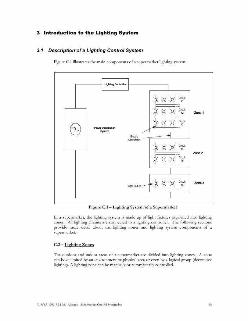
3.1 Description of a Lighting Control System Figure C.1 illustrates the main components of a supermarket lighting system.
Zone 1
Circuit#1
Circuit#2
Circuit#3
Lighting Controller
Power DistributionSystem
Circuit#4
Circuit#5
Circuit#6
Zone 2
Zone 3
ElectricConnection
Light Fixture
Figure C.1 – Lighting System of a Supermarket In a supermarket, the lighting system is made up of light fixtures organized into lighting zones. All lighting circuits are connected to a lighting controller. The following sections provide more detail about the lighting zones and lighting system components of a supermarket.
C.2 – Lighting Zones The outdoor and indoor areas of a supermarket are divided into lighting zones. A zone can be delimited by an environment or physical area or even by a logical group (decorative lighting). A lighting zone can be manually or automatically controlled.

71-MTA-1033-R2.1 MT Alliance - Supermarket Control System.doc 39
The table below describes the different zones that are found in a supermarket. Certain zones can be subdivided into sub-zones (last column), thus providing management and system setting flexibility.
Location Lighting Zone Sub-Zone
Outdoor Parking lot Yes
Signs
Traffic lanes
Unloading zone
Indoor Sales area Yes: aisles, entranceway, cashier area
Refrigerated cases Yes: Based on different products
Decorative lighting Yes: Based on product groups
Service area Yes: Based on peripheral services
Emergency lighting
Office area Yes
Mechanical room
Storage area
Table C.2 – Lighting Zones of a Supermarket A compromise must be made between the size of a lighting zone and the cost of a lighting system. Small lighting zones are more expensive (equipment and installation costs), but offer more flexibility and greater potential for reducing system operating costs.
C.3 – Components of the Lighting System The main component of a lighting system is the light fixture. A light fixture is a lighting unit made up of a light source and parts for distributing light, physically supporting the light source and electrically connecting the light source. A light fixture is made up of the following parts:
Light source: Produces the light Socket tube: Holds the light source in the housing and electrically connects the light
source Ballast: Device to operate a fluorescent light or high intensity discharge (HID) light.
It provides starting voltage while stabilizing the current during operation. There are two types of offloads: magnetic ballasts and electronic ballasts
Reflector: Reflects the light Lens: Made of a transparent material and used to converge the light Housing: Mechanical support that holds together all parts of the light fixture
71-MTA-1033-R2.1 MT Alliance - Supermarket Control System.doc 40
C.3.1 – Lights Different types of lights are available, each having their own specific characteristics. The following characteristics are used for describing a light: Mean Life: A measurement used to compare the average life of a light
source. It is expressed in hours. Efficiency: A measurement used to compare the relationship between
the light flux issued and energy consumed. It is expressed in lumens per watt.
Color Index: A scale that measures the color produced on an object by a
reference light source. This scale is measured in percentage. A low color index means the color of objects is not natural.
Visual Comfort Probability: Visual comfort probability specifies the percentage of
people who are comfortable with the lighting in a given space. A comfort probability of at least 70% is recommended for inside commercial environments.
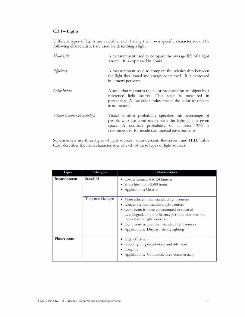
Supermarkets use three types of light sources: incandescent, fluorescent and HID. Table C.3.1 describes the main characteristics of each of these types of light sources.
Types Sub-Types Characteristics
Incandescent Standard Low efficiency: 6 to 24 lumens Short life: 750 –2500 hours Applications: General
Tungsten-Halogen More efficient than standard light sources Longer life than standard light sources Light beam is more concentrated or focused
Less degradation in efficiency per time unit than the incandescent light sources
Light more natural than standard light sources Applications: Display, strong lighting
Fluorescent High efficiency Good lighting distribution and diffusion Long life Applications: Commonly used commercially
71-MTA-1033-R2.1 MT Alliance - Supermarket Control System.doc 41
Types Sub-Types Characteristics
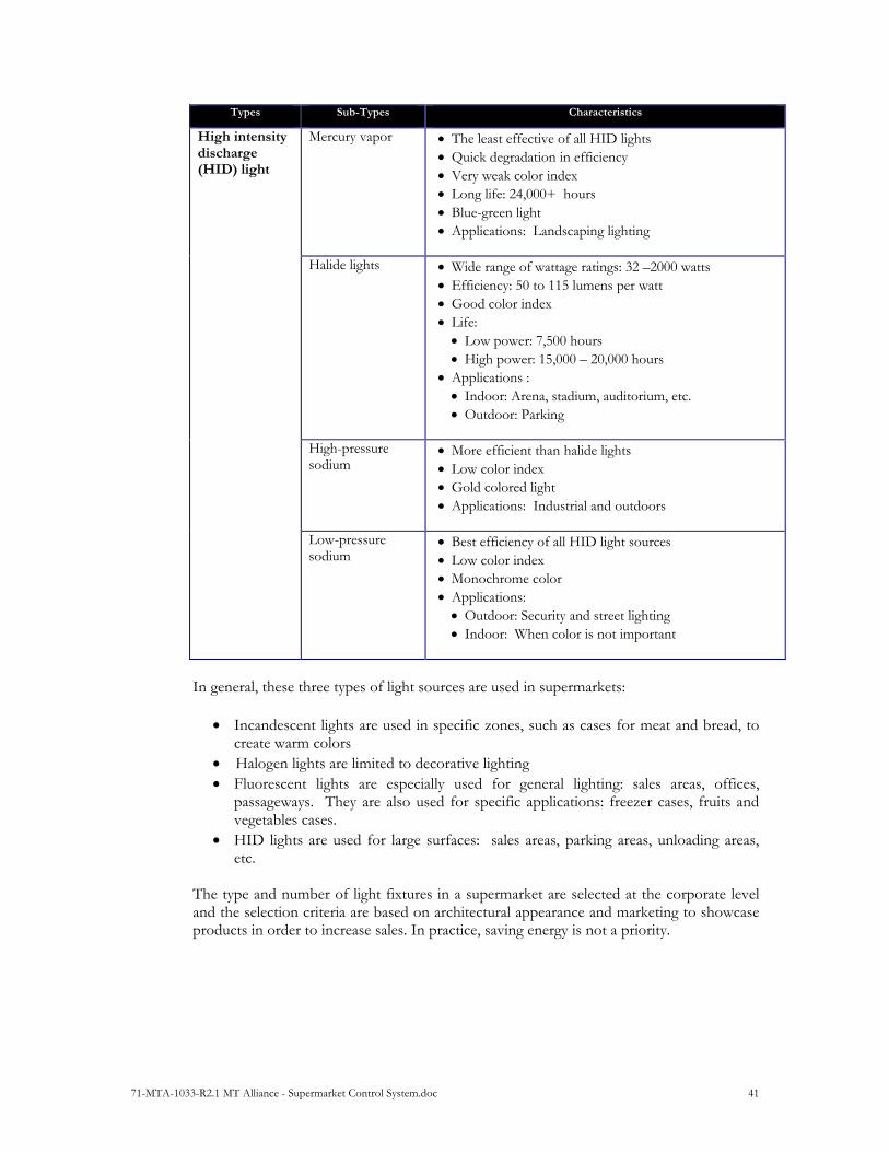
High intensity discharge (HID) light
Mercury vapor The least effective of all HID lights Quick degradation in efficiency Very weak color index Long life: 24,000+ hours Blue-green light Applications: Landscaping lighting
Halide lights Wide range of wattage ratings: 32 –2000 watts Efficiency: 50 to 115 lumens per watt Good color index Life: Low power: 7,500 hours High power: 15,000 – 20,000 hours
Applications : Indoor: Arena, stadium, auditorium, etc. Outdoor: Parking
High-pressure sodium
More efficient than halide lights Low color index Gold colored light Applications: Industrial and outdoors
Low-pressure sodium
Best efficiency of all HID light sources Low color index Monochrome color Applications: Outdoor: Security and street lighting Indoor: When color is not important
In general, these three types of light sources are used in supermarkets:
Incandescent lights are used in specific zones, such as cases for meat and bread, to create warm colors
Halogen lights are limited to decorative lighting Fluorescent lights are especially used for general lighting: sales areas, offices,
passageways. They are also used for specific applications: freezer cases, fruits and vegetables cases.
HID lights are used for large surfaces: sales areas, parking areas, unloading areas, etc.
The type and number of light fixtures in a supermarket are selected at the corporate level and the selection criteria are based on architectural appearance and marketing to showcase products in order to increase sales. In practice, saving energy is not a priority.
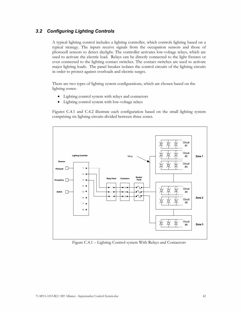
71-MTA-1033-R2.1 MT Alliance - Supermarket Control System.doc 42
3.2 Configuring Lighting Controls A typical lighting control includes a lighting controller, which controls lighting based on a typical strategy. The inputs receive signals from the occupation sensors and those of photocell sensors to detect daylight. The controller activates low-voltage relays, which are used to activate the electric load. Relays can be directly connected to the light fixtures or even connected to the lighting contact switches. The contact switches are used to activate major lighting loads. The panel breaker isolates the control circuits of the lighting circuits in order to protect against overloads and electric surges.
There are two types of lighting system configurations, which are chosen based on the lighting zones:
Lighting control system with relays and contactors Lighting control system with low-voltage relays
Figures C.4.1 and C.4.2 illustrate each configuration based on the small lighting system comprising six lighting circuits divided between three zones.
Zone 1
Circuit#1
Circuit#2
Circuit#3
Zone 2
Zone 3
Circuit#4
Circuit#5
Circuit#6
BreakerPanel
Wiring
ContactorsRelay Panel
1
2
3
4
5
6
7
8
Lighting Controller
Sensors
Photocell
Occupancy
Switch
Figure C.4.1 – Lighting Control system With Relays and Contactors

71-MTA-1033-R2.1 MT Alliance - Supermarket Control System.doc 43
In the lighting control system with and relays and contactors , each zone is defined by connecting all circuits of a zone to a contactor switch. Each contactor is controlled by a relay. The advantage of this configuration is the reduction of the number of outlets in the lighting controller and the number of relays. However, this type of control system is not flexible since each zone is determined based on the connection of the electrical lighting circuits. Moreover, this type of configuration requires more cabling.
In the lighting control system with low-voltage relays (Figure C.4.2), each circuit is connected to a low-voltage relay, which is connected to the outlet of the lighting controller. Lighting zones are defined logically in the lighting controller by activating the relays associated with a given zone. This configuration offers far more flexibility since each zone can be easily redefined and requires less cabling than the lighting control system with relays and contactors. However, the large number of relays required increases installation costs.
Circuit#1
Circuit#2
Circuit#3
Circuit#4
Circuit#5
Circuit#6
BreakerPanel WiringRelay Panel
1
2
3
4
5
6
7
8
Lighting Controller
Sensors
Photocell
Occupancy
Switch
Zone 1
Zone 2
Zone 3
Figure C.4.2 – Lighting Control System With Low-Voltage Relays The control system may be a combination of both configurations, with some of the circuits having a fixed connection to the contactors and the other circuits being individually connected to the low-voltage relays. This allows more flexibility than the contact switch with relay configuration and reduces the number of relays required.
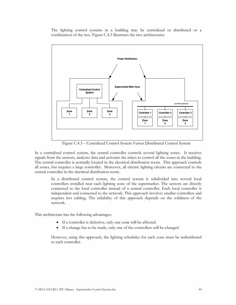
71-MTA-1033-R2.1 MT Alliance - Supermarket Control System.doc 44
The lighting control systems in a building may be centralized or distributed or a combination of the two. Figure C.4.3 illustrates the two architectures.
Centralized ControlSystem
Zone1
Zone3
Zone2
Power Distribution
Supermarket Main Area
Controller 1
Zone1
Zone3
Zone2
Controller 2 Controller 3
LonWorks Network
Figure C.4.3 – Centralized Control System Versus Distributed Control System
In a centralized control system, the central controller controls several lighting zones. It receives signals from the sensors, analyzes data and activates the relays to control all the zones in the building. The central controller is normally located in the electrical distribution room. This approach controls all zones, but requires a large controller. Moreover, all electric lighting circuits are connected to the central controller in the electrical distribution room.
In a distributed control system, the control system is subdivided into several local controllers installed near each lighting zone of the supermarket. The sensors are directly connected to the local controller instead of a central controller. Each local controller is independent and connected to the network. This approach involves smaller controllers and requires less cabling. The reliability of this approach depends on the solidness of the network.
This architecture has the following advantages:
If a controller is defective, only one zone will be affected. If a change has to be made, only one of the controllers will be changed.
However, using this approach, the lighting schedules for each zone must be redistributed to each controller.

71-MTA-1033-R2.1 MT Alliance - Supermarket Control System.doc 45
3.3 Lighting Control Strategy in the Supermarket
The lighting control strategy is based on two priorities: operations and sales. This means that the objectives are:
To maintain the appropriate operating conditions: employee safety, product quality To provide lighting that showcases products in order to increase sales
Flexibility is an important component for the following reasons:
A supermarket’s opening and closing hours may vary, and stores are open for increasingly longer periods of time. This impacts a supermarket’s activities: they are more spread out throughout the day. Lighting must be adjusted based on occupation hours and the type of activity (e.g. occupation by customers during the day versus occupation by support staff at night).
Supermarkets are becoming larger and larger and are offering more and more services through independent retailers. This impacts the lighting system by creating new zones that must be controlled independently.
In general, the time switching control strategy is highly used in supermarkets since it is less costly to implement. To obtain gradual or partial lighting control, the lighting circuits are grouped alternatively so that a percentage of the lighting fixtures (generally 50%) is turned off while another is on. This strategy is known as the 50/50 strategy (Figure C.5.1). It balances the time the lights are on and facilitates maintenance while providing adequate lighting
Zone 1
Zone 2
SupermarketMain Area
RefrigeratedCases
Figure C.5.1: 50/50 Lighting Strategy

71-MTA-1033-R2.1 MT Alliance - Supermarket Control System.doc 46
Table C.5.1 shows the different lighting control techniques: automatic or manual control.
Control Type Control Technique Description and Considerations
Automatic Time switching Light fixtures are switched to On/Off state based on the programmed schedule. In this control technique, different types of timers are used:
Mechanical timer Electronic timer Programmable software timer
This type of control must include a manual control with time-out to override the schedule or lighting timer. After the time-out period, the lighting system must automatically go back to time switching mode.
Supermarket Applications: Electronic or mechanical timers are used in the zones with set schedules. Programmable software timers are used in occupation zones with variable schedules.
Time Switching / modulation based on ambient lighting
Light fixtures are switched or modulated in intensity based on the ambient lighting levels when there is daylight.
A photocell sensor is used to convert visible rays:
Into a digital electronic signal to switch one or more controller lighting relays (circuit).
Into an analog electronic signal to modulate the lighting controller’s analog outlet. This modulates the lighting intensity based on the level of ambient light.
The electric photocell sensors used for outdoor applications normally face north in the northern hemisphere to ensure constant illumination on the sensor. This eliminates any contribution from the sun.
In general, outdoor photocell sensors must not be used for indoor applications because of the low sensitivity and their limited adjustment level.
Supermarket Applications: The switching mode is used for outdoor applications. Modulation mode is used for indoor applications when there are skylights.
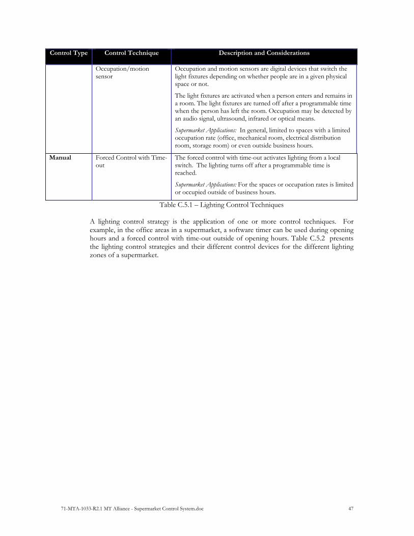
71-MTA-1033-R2.1 MT Alliance - Supermarket Control System.doc 47
Control Type Control Technique Description and Considerations
Occupation/motion sensor
Occupation and motion sensors are digital devices that switch the light fixtures depending on whether people are in a given physical space or not.
The light fixtures are activated when a person enters and remains in a room. The light fixtures are turned off after a programmable time when the person has left the room. Occupation may be detected by an audio signal, ultrasound, infrared or optical means.
Supermarket Applications: In general, limited to spaces with a limited occupation rate (office, mechanical room, electrical distribution room, storage room) or even outside business hours.
Manual Forced Control with Time-out
The forced control with time-out activates lighting from a local switch. The lighting turns off after a programmable time is reached.
Supermarket Applications: For the spaces or occupation rates is limited or occupied outside of business hours.
Table C.5.1 – Lighting Control Techniques A lighting control strategy is the application of one or more control techniques. For example, in the office areas in a supermarket, a software timer can be used during opening hours and a forced control with time-out outside of opening hours. Table C.5.2 presents the lighting control strategies and their different control devices for the different lighting zones of a supermarket.

71-MTA-1033-R2.1 MT Alliance - Supermarket Control System.doc 48
Lighting Zone
Control Strategy Control Devices
Parking and Signs Time switching on a schedule in conjunction with switching based on ambient lighting.
Light fixtures activated in the dark, on all night and off at daylight.
Timers, programmable lighting schedules and photocell sensors
Traffic Lanes and Unloading Area
Time switching along with switching based on ambient lighting.
Light fixtures activated in the dark and on all night for security
Timers, programmable lighting schedules and photocell sensors
Peripheral Area Services and Sales Area: Aisles, Entranceway and Cashier Area
Time switching Light fixtures are on during the
business areas and turned off 50/50 in unoccupied mode.
Programmable lighting schedules
Sales Area With Energy Optimization
Time switching along with modulation based on ambient lighting.
Light fixtures turned off outside of opening hours and intensity modulated based on ambient lighting based on opening hours.
Programmable lighting schedules and photocell sensors
Refrigerated and Freezer Cases
Time switching Activated during business hours and
several hours outside of business hours so that cases can be filled. Turned off the rest of the time.
Programmable lighting schedules
Decorative Lighting Time switching Activated during business hours,
turned off during unoccupied periods
Programmable lighting schedules
Office, Mechanical Room, Storage Room
Time switching along with occupation detection and forced control with time-out
Activated during business hours and activated by the occupation sensor or manually forced command
Programmable lighting schedule, occupation detector, switch with time-out
Emergency lighting Controlled by a separate control system connected to an emergency generator.
Table C.5.2 – Control Strategy for Lighting Zones of a Supermarket
71-MTA-1033-R2.1 MT Alliance - Supermarket Control System.doc 49
Revision History
REV Description Revised by Date 1.0 Creation and formatting of the document, based on 71-MTA-1008
(French version) Rossion 12-sep-03
1.1 Document Revision and corrections JMT, JG, CBC
18-sep-03
2.0 Document Release JG 29-sep-03 2.1 Cover page and formatting ER 10-Mar-2015