mississippi test methodsmdot.ms.gov/documents/materials/manuals/inspection, testing, and... ·...
TRANSCRIPT

Materials Division Inspection, Testing and Certification Manual Version 2.0
April 2010 - 212 -
Appendix B – Mississippi Test Methods
Index of Mississippi Test Methods
Test Number Title Page Number
MT-6 Nuclear Determination of Bitumen Content of Bituminous Paving Mixtures B-1
MT-7 Moisture-Density Relations of Soils Using Family of Curves B-3
MT-8 Moisture-Density Relations of Soils B-8
MT-9 Moisture-Density Relations of Treated Soils B-13
MT-10 In-Place Density of Soil B-20
MT-11 Preparation of Field Specimens of Soil Cement B-22
MT-12 Liquid Curing Compound B-24
MT-15 Calibration of Nuclear Density and Moisture Gauges B-25
MT-16 Nuclear Method for Field In-Place Density Determination B-29
MT-17 Nonreflective Jiggle and Reflective Pavement Markers B-31
MT-20 Method of Test for Evaluating Color by Means of Chromaticity Coordinates B-39
MT-24 Determination of the Specific Gravity of Fine Aggregate Using the LeChatelier Flask B-42
MT-25 Design of Soil-Cement Mixtures B-43
MT-26 Compressive Strength of Soil-Cement Cylinders and Cores B-47
MT-27 Design of Soil-Lime-Water Mixtures B-48
MT-29 Determination of Organic Content of Soils - Loss by Ignition B-52
MT-30 pH Determination on Soils B-54
MT-31 Quantitative Analysis of Hot Bituminous Mixtures B-55
MT-39 Analysis of Cement, Agricultural Limestone, Fly Ash, and Hydrated Lime B-59
MT-40 Analysis of Hydraulic Cement by Atomic Absorption B-62
MT-41 The Atomic Absorption Method of Analysis of Agricultural Limestone B-66
MT-53 Standard Method of Test for Barbed Wire B-69
MT-58 Soluble Sulfate Ion in Soils and Water B-70
MT-59 Determination of Loss of Coating of HMA (Boiling Water Test) B-72
MT-61 Method of Test for determining Soil Resistivity B-74
MT-63 Resistance of Bituminous Paving Mixtures to Stripping (Vacuum Saturation Method) B-77
MT-64 Asphalt Retention and Change in Area of Geotextile Pavement Fabric B-83
MT-70 Reflective Intensity of Highway Traffic Striping Materials Using a Mirolux 12
Retroreflectometer
B-85

Materials Division Inspection, Testing and Certification Manual Version 2.0
April 2010 - 213 -
MT-71 Cross-Calibration of Troxler Asphalt Content Gauges, Model 3241 B-86
MT-73 Method of Tests for Bituminous Adhesives (Standard Type) B-88
MT-74 Determination of Pavement Smoothness Using a Profilograph B-90
MT-75 Testing of Glass Beads B-93
MT-76 Microwave Method for Determining the Moisture Content of Hot Bituminous Mixtures B-97
MT-78 Volumetric Mix Design of Hot Bituminous Paving Mixtures Using the Superpave
Gyratory Compactor
B-99
MT-79 Design of Soil-Lime-Fly Ash Mixtures B-108
MT-80 Volumetric Mix Design Procedure for Stone Matrix Asphalt (SMA) B-110
MT-81 Preparation and Testing of Stone Matrix Asphalt (SMA) Mortars B-124
MT-82 Draindown Testing of Stone Matrix Asphalt Mixtures B-127
MT-83
MT-84
MT-85
Mix Design of Open Graded Friction Course Hot Mix Asphalt
Permeability of Open Graded Friction Course Asphalt Mixtures
Abrasion Testing of Open Graded Friction Course Asphalt Mixtures
B-130
B-138
B-144

Rev. 6/01/05 Mississippi Department of Transportation MT-6
MT6- Nuclear Determination of Bitumen Content of Bituminous Paving Mixtures
PURPOSE: To establish a standard procedure for determining the bitumen content of hot bituminous
paving mixtures by use of a nuclear bitumen content gauge. 1. APPARATUS
1.1 Troxler Asphalt Content Gauges, Models 3241-A, 3241-B and 3241-C; CPN Corporation AC-2
Asphalt Content Gauge, or approved equal. 1.2 Balance - Mettler PC 16, or approved equal. 1.3 Mechanical convection oven capable of maintaining a temperature of 300°F ± 5°F. 1.4 Thermometer with a temperature range of 50° to 400°F (10° to 204°C) with sensitivity of 5°F
(2.8°C). 1.5 Miscellaneous Equipment 1.5.1 3/4-inch board approximately 14 inches square. 1.5.2 Supply of wrapping paper to cover board. 1.5.3 A trowel or small spade for use in filling specimen container. 1.5.4 A supply of rags and solvent for cleaning equipment.
2. CALIBRATION OF GAUGES 2.1 Troxler Asphalt Content Gauge, Model 3241-A. 2.1.1 Prepare three (3) calibration specimens in accordance with the gauge instruction manual. The
specimens must be prepared at the same weight within ±1 gram. The aggregate blend and asphalt cement to be used in the mix must be used to prepare the specimens. Prepare one specimen at 1% higher than the design bitumen content, one specimen at the design bitumen content, and one specimen at 1% lower than the design bitumen content. All calibration specimens shall be prepared and tested at a uniform temperature within ± 10°F (6°C) and as close as possible to the job-mix temperature. (This may necessitate heating the specimens in an oven at a temperature not to exceed the job-mix temperature.)
2.1.2 Using two (2) of the calibration specimens (one at 1% higher than the design bitumen content
and one at 1% lower than the design bitumen content), calibrate the gauge in accordance with the gauge instruction manual.
2.1.3 Check the gauge calibration by taking the average of fifteen (15) 4-minute counts using the
calibration specimen prepared at the design bitumen content. If the average is ± 0.06% or more from the design bitumen content, check the gauge calibration procedures. If the average is less than ± 0.06% from the design bitumen content, adjust the intercept to make the gauge read the design bitumen content. This adjustment is accomplished by using the calibration offset procedure as set out in the gauge instruction manual.
2.2 Troxler Asphalt Content Gauges, 3241-B and 3241-C; CPN Corporation AC-2 Asphalt Content
Gauge.
B-1

Rev. 6/01/05 Mississippi Department of Transportation MT-6
2.2.1 Prepare three (3) or more calibration specimens in accordance with the gauge instruction manual. The specimens must be prepared at the same weight within ± 1 gram. The aggregate blend and asphalt cement to be used in the mix must be used to prepare the specimens. The range of bitumen content of the specimens (lowest to the highest) shall not exceed three percent (3%) and shall encompass and be equally distributed above and below the design bitumen content. All calibration specimens shall be prepared and tested at a uniform temperature within ± 10°F (6°C) and as close as possible to the job-mix temperature. (This may necessitate heating the specimens in an oven at a temperature not to exceed the job -mix temperature.)
2.2.2 Using the three (3) or more calibration specimens prepared as outlined in Subsection 2.2.1,
calibrate the gauge in accordance with the gauge instruction manual. 2.2.3 Check gauge calibration (correlation factor, fit coefficient or correlation coefficient; acceptable
value is 0.995 or greater) for acceptance in accordance with the gauge instruction manual. 2.3 Record calibration and supporting data (background count; temperature and weight of
calibration specimens). 2.4 Gauge must be calibrated for each job-mix formula. A new calibration will be required when
there is a change in aggregate or bitumen source. When gauge repairs are made, check calibration.
3. PREPARATION OF TEST SPECIMEN
3.1 Obtain a representative sample of the mix and reduce to test specimen size in accordance with
AASHTO T 248, Method B. 3.2 Fill specimen pan with the mix to within ± 1 gram of the weight of the calibrated specimen. 3.3 Measure and record the temperature of the test specimen. All test specimens shall be tested at a
temperature within ± 10°F (6°C) of the calibrated specimens.
4. PROCEDURE 4.1 With the proper job-mix calibration in the gauge, place the test specimen in the gauge chamber
and take a sixteen (16) minute-measure count in accordance with the gauge instruction manual. NOTE: (FOR CENTRAL LABORATORY USE ONLY) When it is necessary to test a specimen after it cools, heat the test specimen in an oven to 290°F - 300°F for a minimum of three (3) hours before testing. 4.2 The sixteen (16) minute-measure count is the bitumen content of the specimen. 4.3 Remove specimen from the gauge, empty and clean the specimen pan.
5. REPORT Report the bitumen content to the nearest 0.01 percent.
6. CORRECTED BITUMEN CONTENT The reported bitumen content shall be corrected for moisture as set out in S.O.P. No. TMD-11-31-00-000
B-2

Rev. 6/01/05 Mississippi Department of Transportation MT-7
MT-7 Moisture-Density Relations of Soils Using Family of Curves
PURPOSE: To establish a rapid method of test for determining the moisture-density relations of soils. SCOPE:
1.1 This method of test is intended for determining the relationship between the moisture content and density of a soil utilizing the family of moisture-density curves and a one point proctor, compacted as specified herein. This method is an acceptable alternate to MT-8, Moisture-Density Relations of Soils, under the conditions set forth in these provisions. These method is applicable to embankment soils, design soils, and to untreated subbase and base materials. 1.2 To obtain maximum utilization of the family of curves, the person using this method of test:
(1) Must familiarize himself thoroughly with the materials being tested. (2) Must be experienced in the use of the AASHTO Classification System. (3) Should be familiar with the Unified Classification System to be able to recognize the diference between
an SP and SM soil within the A-2 AASHTO Group.
1.3 When Case 1 or Case 2 is referred to herein, this shall be interpreted to mean: Case 1 – When approximately 90 percent or more of the soil or material passes the No. 4 sieve.
Case 2 – When approximately 10 percent or more of the soil or material is retained on the No. 4 sieve.
APPARATUS:
2.1 Molds
(1) 4.0 inch inside diameter mold having a capacity of 0.333 ft3 (2) 6.0 inch inside diameter mold having a capacity of 0.10 ft3
2.2 Rammer – A metal rammer having a 2 inch diameter circular face, or a segmented face (used with mechanical tampers) having an area equivalent to a 2 inch diameter circle, and weighing 5.5 pounds. (The use of a mechanical tamper with a segmented rammer face is not only permissible but is desirable.) The rammer shall be equipped with a suitable arrangement to control the height of drop to a free fall or twelve inches above the elevation of the soil. 2.3 Sample Extruder (optional) – A jack, lever, frame, or other device adapted for the purpose of extruding compacted specimens from the mold. Note: It has been found that an extruder is very useful in breaking up heavy clay specimens, after compaction, by slicing the specimen into very thin layers during extrusion. 2.4 Balances – A balance of at least 1000 g capacity sensitive to 0.1 g. 2.5 Drying Apparatus – A thermostatically-controlled drying oven capable of maintaining a temperature of 110+5 C. 2.6 Straight Edge – A rigid steel straight edge approximately twelve inches in lengh and having one beveled edge. 2.7 Sieves – ½ inch and No. 4 (If required) 2.8 Mixing Tools – Miscellaneous tools such as mixing pan, spoon, trowel, spatula, knife, etc.; a suitable mechanical device for thoroughly mixing the sample of soil with increments of water is desirable.
B-3

Rev. 6/01/05 Mississippi Department of Transportation MT-7
SAMPLE: 3.1 If a soil sample is damp when received from the field, it shall be dried until it can be easily broken up with a trowel; drying may be in air or by use of drying apparatus such that the temperature of the sample does not exceed 60 C. Then thoroughly break up the aggregations in such a manner as to avoid reducing the natural size of individual particles. 3.2 Determine by sieving or visual inspection if the soil should be tested under Case 1 or Case 2.
(1) For Case 1 – Select a representative sample of the soil prepared as described in 3.1 and weighing approximately 7 pounds.
(2) For Case 2 – Determine the moisture content of the soil prepared as described in 3.1. Separate the
sample on the ½ inch sieve, determining the percentage of the retained portion. Select a representative sample of the fraction passing the ½ inch sieve and weighing approximately 20 pounds.
PROCEDURE:
4.1 Thoroughly mix the selected representative sample with sufficient water to bring the sample to slightly less than its optimum moisture. (From 1 to 3 percentage points below optimum moisture.) 4.2 Case 1 – Form a specimen by compacting the prepared soil in the 4 inch mold (with collar attached) in three equal layers to give a total compacted depth sufficient to fill the mold, but not to exceed approximately five inches. Compact each layer by twenty-five uniformly distributed blows from the rammer dropping free from a height of 12 inches above the elevation of the soil. During compaction, the mold shall rest on a solid, rigid foundation. Following compaction, remove the extension collar, carefully trim the compacted soil even with the top of the mold by means of the straight-edge and weigh. Record weight of specimen and mold as “D”; weight of mold as “E”. 4.3 Case 2 – Form a specimen by compacting the minus ½ inch portion of the prepared soil in the 6 inch mold (with collar attached) in four equal layers to give a total compacted depth of about 6.5 inches. Compact each layer by fifty-six (56) uniformly distributed blows from the rammer, as described in 4.1, and weigh. Record weight of specimen as “D”; weight of mold as “E”. 4.4 Remove the material from the mold and slice vertically through the center. Take a representative sample of the material, weighing not less than 100 g for fine-grained soils, or not less than 500 g from coarse-grained soils, from the full height of one of the cut faces; weigh immediately; dry to a constant weight and weigh. Determine weight of container.
CALCULATIONS:
5.1 Calculate the moisture content of the soil specimen as follows: w = A – B x 100 B – C Where, w = percentage of moisture in the specimen, based on oven-
dry weight of the soil A = weight of container and wet soil B = weight of container and dry soil C = weight of container
5.2 Calculate the dry weight per cubic foot of the compacted soil, as follows:
(1) Case 1: W = (D – E) x 30 x 100 w + 100
B-4

Rev. 6/01/05 Mississippi Department of Transportation MT-7
(2) Case 2: W = (D – E) x 10 x 100 w + 100
Where, W = dry weight, in pounds per cubic foot of compacted soil, D = weight of compacted specimen and mold in pounds E = weight of mold, in pounds
w = percentage of moisture in the specimen, based on oven- dry weight of the soil.
NOTE: When gram scales are used, the results obtained under 5.2 should be divided by 453.6.
MOISTURE-DENSITY RELATIONSHIP AS DETERMINED FROM THE FAMILY OF CURVES:
6.1 Case 1 – Plot the dry density and moisture content of the compacted specimen on Figure 1 containing Curves B & C. (If the point falls above Curve B, the Family of Curves shall not be used.)
(1) A1, A4, A6, and A7 Soils – Project a line parallel with the nearest diagonal line to the intersection of
Curve B. The corresponding dry density and moisture content at the intersection of Curve B shall be recorded as the Standard Density and Optimum Moisture of the Sample.
NOTE: For all A1, A4, A6, and A7 Soils, Curve C shall be disregarded, use Curve B. In the event a question should arise as to the classification of the particular soil being tested, the Engineer will require that a second specimen must be compacted at a slightly higher moisture content and plotted to determine whether to use Curve B or Curve C when the density is within the range of Curve C. (2) A2 and A3 Soils – Project a line parallel with the nearest diagonal line to its intersection with the first
curve (Curve C or B) crossed. The corresponding dry density and moisture content at the intersection shall be recorded as the Standard Density and Optimum Moisture of the sample.
NOTE: Most A3 soils and some A2 (SP-SM) Soils will fall within the limits of Curve C. In the event a question should arise as to the classification of the particular soil being tested, the Engineer will require that a second specimen must be compacted at a slightly higher moisture content and plotted to determine whether to use Curve B or Curve C when the density is within the range of Curve C.
6.2 Case 2 – Plot the dry density and moisture content of the compacted specimen on Figure 1 containing Curve A. Project a line parallel with the nearest diagonal line to the intersection of Curve A. The corresponding dry density and moisture content at this intersection shall be recorded as the Standard Density and Optimum Moisture of the – ½ inch material. (If the point falls above Curve A, the Family of Curves shall not be used.)
(1) Optimum Moisture Content – The “optimum moisture content” of the whole sample, under Case 2 (when the sample contains + ½ inch material), shall be obtained from the following formula:
OMw = 3 (% Retained on ½ inch sieve) + OMP (% Passing ½ inch sieve) 100 100 Where, OMw = Optimum Moisture of Whole Sample OMP = Optimum Moisture of – ½ inch fraction NOTE: In this formula, the moisture content of the plus ½ inch material is assumed to be 3 percent.
6.3 Standard Density – The standard density of the whole sample, under Case 2 (when the sample contains + ½ inch material), shall be obtained by applying the percentage of + ½ inch material, as determined above, to the Nomograph (Figure 2). (The Nomograph is available as TMD-520.) In determining the standard density from the Nomograph, the Bulk Specific Gravity of the + ½ inch material, as determined in accordance with AASHTO T 85, will be used. It will not be necessary to determine the specific gravity for each density determination after sufficient experience has been gained so that a value may be assigned to the specific type and source of the material being tested.
B-5

Rev. 6/01/05 Mississippi Department of Transportation MT-7
Figure 1
B-6

Rev. 6/01/05 Mississippi Department of Transportation MT-7
Figure 2
B-7

Rev. 6/01/05 Mississippi Department of Transportation MT-8
MT-8 – Moisture-Density Relations of Soils Using Family of Curves
PURPOSE: To establish a method of test for determination of the moisture-density relations of soils. 1. SCOPE 1.1 This method of test is intended for determining the relationship between the moisture content and density of a soil compacted in a mold of a given size with a 5.5 lb hammer dropped from a height of 12 in. The method is otherwise known as Method MT-8M and is a modification of AASHTO T 99. 1.2 These methods are applicable to embankment soils, design soils, and untreated subbase and base materials. 1.3 When CASE 1 or CASE 2 is referred to herein, this shall be interpreted to mean: 1.3.1 CASE 1: When approximately 90 percent or more of the soil or material passes the No. 4 sieve. 1.3.2 CASE 2: When approximately 10 percent or more of the soil or material is retained on the No. 4 sieve. 2. APPARATUS 2.1 MOLDS 2.1.1 4.0 in. inside diameter mold having a capacity of 0.000 943 0.000 008 m3. 2.1.2 6.0 in. inside diameter mold having a capacity of 0.002 124 0.000 021 m3. 2.2 RAMMER. A metal rammer having a 2 inch diameter circular face, or a segmented face (used with mechanical tampers) having an area equivalent to a 2 inch diameter circle and a mass of 5.5 pounds. (The use of a mechanical tamper with a segmented rammer face is not only permissible but is desirable.) The rammer shall be equipped with a suitable arrangement to control the height of drop to a free fall of 12 inches above the elevation of the soil. 2.3 SAMPLE EXTRUDER (optional). A jack, lever, frame, or other device adapted for the purpose of extruding compacted specimens from the mold. 2.4 BALANCES. A balance or scale of at least 12 kg (25 lb) capacity sensitive to 5 g (0.01 lb); and a
balance of at least 1000-g capacity sensitive to 0.1 g. 2.5 DRYING OVEN. A thermostatically-controlled drying oven capable of maintaining a temperature of 110 5C (230 ± 9° F), or other suitable means for drying moisture samples. 2.6 STRAIGHTEDGE. A rigid steel straightedge approximately 12 inches in length and having one (1) beveled edge. 2.7 SIEVES. 1/2 inch, and No. 4 (if required, see Subsection 3.3 below) 2.8 MIXING TOOLS. Miscellaneous tools such as mixing pan, spoon, trowel, spatula, knife, etc.; a suitable mechanical device for thoroughly mixing the sample of soil with increments of water is desirable.
B-8

Rev. 6/01/05 Mississippi Department of Transportation MT-8
3. SAMPLE 3.1 If the soil sample is damp when received from the field, it shall be dried until it can be easily broken up with a trowel; drying may be in air or by use of drying apparatus such that the temperature of the sample does not exceed 60C (140 °F). Then thoroughly break up the aggregations in such a manner as to avoid reducing the natural size of individual particles. 3.2 After the above drying and pulverizing, the moisture content of the soil should be determined. If preferable, the soil may be dried to constant mass (zero moisture content). 3.3 Determine by sieving or visual inspection if the soil should be tested under CASE 1 or CASE 2. 3.3.1 FOR CASE 1, select a representative sample of the soil prepared as described in Subsection 3.1 and with a mass of approximately 7 lb. 3.3.2 FOR CASE 2, separate the sample, prepared as described in Subsection 3.1, on the 1/2 inch sieve, determining the percentage of the retained portion. Select a representative sample of the fraction passing the 1/2 inch sieve and weighing approximately 20 lb. 4. PROCEDURE 4.1. Thoroughly mix the selected representative sample with sufficient water to dampen it to approximately four percentage points below the estimated optimum moisture content. 4.2 CASE 1: Form a specimen by compacting the prepared soil in the 4 inch mold (with collar attached) in three (3) equal layers to give a total compacted depth sufficient to fill the mold, but not to exceed approximately 127 mm. Compact each layer by twenty-five (25) uniformly distributed blows from the rammer dropping free from a height of 5 inches above the elevation of the soil. During compaction, the mold shall rest on a solid, rigid foundation. Following compaction, remove the extension collar, carefully trim the compacted soil even with the top of the mold by means of the straightedge, and measure its mass. Record mass of specimen and mold as “D” and mass of mold as "E." 4.3 CASE 2: Form a specimen by compacting the minus 1/2 inchportion of the prepared soil in the 6 inch mold (with collar attached) in four (4) equal layers to give a total compacted depth of about 6.5 inches. Compact each layer by fifty-six (56) uniformly distributed blows from the rammer, as described in Subsection 4.2 above, and determine mass. Record mass of specimen as “D;” and mass of mold as "E." 4.4 Remove the material from the mold and slice vertically through the center. Take a represen- tative sample of the material, with a mass of not less than 100 g for fine-grained soils, or not less than 500 g for coarse-grained soils, from the full height of one of the cut faces; weigh immediately; dry to a constant mass and measure its mass. Determine mass of container. 4.5 Thoroughly break up the remaining portion of the molded specimen and add to the remaining portion of the sample being tested. Add water in sufficient amount to increase the moisture content of the soil sample by one or two percentage points and mix; repeat the procedure described in Sub- section 4.2 and Subsection 4.4 for each increment of water added. Continue this series of determi- nations until there is either a decrease or no change in the wet mass of the compacted soil and mold.
B-9

Rev. 6/01/05 Mississippi Department of Transportation MT-8
NOTE: This procedure has been found satisfactory in most cases. However, in instances where the soil material is fragile in character and will reduce significantly in grain size due to repeated compac- tion, and in cases where the soil is a heavy-textured clayey material into which It is difficult to incor- porate water, a separate and new sample shall be used in each compaction test. In these cases, separate samples shall be thoroughly mixed with amounts of water sufficient to cause the moisture contents of the samples to vary by approximately one, or two, percentage points. The moisture contents selected shall bracket the estimated optimum moisture content, thus providing samples which, when compacted, will increase in mass to the maximum density and then decrease in mass. 5. CALCULATIONS 5.1 Calculate the moisture content of the soil specimen for each trial, as follows: w = A - B x 100 B - C Where, w = percentage of moisture In the specimen, based on oven-dry mass of the soil,
A = mass of container and wet soil (Subsection 4.4)
B = mass of container and dry soil (Subsection 4.4)
C = mass of container. 5.2 Calculate the dry mass per cubic meter of the soil as compacted, for each trial, as folllows: Case 1: W = (D - E) x 1059.43 x 100 w + 100 Case 2: W = (D - E) x 470.74 x 100 w + 100 Where, W = dry mass, in kilograms per cubic meter of compacted soil, D = mass of compacted specimen and mold in kilograms (Subsection 4.2), E = mass of mold, in mass, w = percentage of moisture in the specimen, based on oven-dry mass of the soil. 6. MOISTURE-DENSITY RELATIONSHIP 6.1 The calculations in Section 5 shall be made to determine the moisture content and corres- ponding oven-dry mass per cubic meter (density) for each of the compacted soil samples. The densities of the soil shall be plotted as ordinates and corresponding moisture contens as abscissa.
B-10

Rev. 6/01/05 Mississippi Department of Transportation MT-8
6.2 OPTIMUM MOISTURE CONTENT. When the densities and corresponding moisture contents for the soil have been determined and plotted as indicated in paragraph (a), it will be found that by connecting the plotted points with a smooth line, a curve is produced. The moisture content corresponding to the peak of the curve shall be termed the "optimum moisture content" of the soil under Case 1, and of the minus 1/2 inch fraction under Case 2. The "optimum moisture content" of the whole sample, under Case 2 (when the sample contains plus 1/2 inch material), shall be obtained from the following formula: OMw = 3 ( retained on 12.5 mm sieve + OMp ( passing 12.5 mm sieve) 100 100 where, OMw = Optimum Moisture of whole sample, OMp = Optimum Moisture of minus 12.5 mm fraction. NOTE: In this formula, the moisture content of the plus 12.5 mm material is assumed to be 3 percent. 6.3 STANDARD DENSITY. The oven-dry mass per cubic meter of the soil at optimum moisture content shall be termed "standard density" under the above compaction. The density at optimum moisture is the standard density of the soil under Case 1, and of the minus 1/2 inch fraction under Case 2. The standard density of the whole sample, under Case 2 (when the sample contains plus 1/2 inch material), shall be obtained by applying the percentage of plus 1/2 inch material, as determined above, to the Nomograph shown below. (The Nomograph is available as Form TMD- 520.) In determining the standard density from the Nomograph, the Bulk Specific Gravity of the plus ½ inch material, as determined in accordance with AASHTO T 85, will be used. It will not be necessary to determine the specific gravity for each density determination after sufficient experience has been gained so that a value may be assigned to the specific type and source of the material being tested. NOTE: Closer determinations may be made by using approximately one percent (1%) increments of moisture which, when plotted, result in at least two points on each side of the optimum moisture.
B-11

Rev. 6/01/05 Mississippi Department of Transportation MT-8
B-12

Rev. 6/01/05 Mississippi Department of Transportation MT-9
MT-9 Moisture-Density Relations of Treated Soils
PURPOSE: To establish a method of test for determination of the moisture-density relations of soils treated with Portland cement, hydrated lime, or hydrated lime and fly ash. 1. SCOPE 1.1 This method covers procedures for determining the relationship between the moisture content and density of soil-cement, soil-lime, or soil-lime-fly ash mixtures compacted in a mold of a given size with a 5.5 pound rammer dropped from a height of 12 inches. Method A is to be used for design tests and for any preliminary tests made prior to beginning of construction. Method B is to be used after roadway mixing for determination of the standard density of the mixed material. The method, other- wise known as Method MT-9M, is a modification of AASHTO T 134. 1.2 When Case 1 or Case 2 is referred to herein, this shall be interpreted to mean: 1.2.1 CASE 1: When approximately 90 percent or more of the soil or material passes the 4.75 mm
sieve. 1.2.2 CASE 2: When approximately 10 percent or more of the soil or material is retained on the 4.75 mm sieve. 2. APPARATUS 2.1 MOLDS 2.1 1 4.0 inch inside diameter mold having a capacity of 1/30 ft³. 2.1.2 6.0 inch inside diameter mold having a capacity of 1/10 ft3.
2.2 RAMMER. A metal rammer having a 2 inch diameter circular face, or a segmented face with an area equivalent to a 2 inch diameter circle, with a mass of 5.5 pounds. (The use of a mechanical tamper with a segmented rammer is not only permissible but is desirable.) The rammer shall be equipped with a suitable arrangement to control the height of drop to a free fall of 12 inches above the elevation of the mixture. 2.3 SAMPLE EXTRUDER. A jack, lever, frame, or other device adapted for the purpose of extruding compacted specimens from the mold. 2.4 BALANCE. A balance or scale of at least 12 kg (25 lb) capacity sensitive to 5 g (0.01 lb); and a
balance of at least 1000-g capacity sensitive to 0.1 g 2.5 DRYING OVEN. A thermostatically-controlled drying oven capable of maintaining a temperature of 110 + 5°C (230 + 9°F), or other suitable means for drying moisture samples.
2.6 STRAIGHTEDGE. A rigid steel straightedge approximately 12 inches in length and having one (1) beveled edge. 2.7 SIEVES. 1/2 inch and No. 4.
B-13

Rev. 6/01/05 Mississippi Department of Transportation MT-9
2.8 MIXING TOOLS. Miscellaneous tools such as mixing pan, spoon, trowel, spatula, knife, etc.; a suitable mechanical device for thoroughly mixing the sample of soil with cement, lime, and/or lime-fly ash, and with increments of water, is desirable.
METHOD"A"
(For Use In Design And Other Preconstruction Tests) 3. SAMPLE 3.1 If the soil sample is damp when received from the field, dry it until it can be broken up easily with a trowel; drying may be in air or by use of drying apparatus such that the temperature of the sample does not exceed 60°C (140 °F). Then thoroughly break up the aggregations in such a manner as to avoid reducing the natural size of individual particles.
3.2 After the above drying and pulverizing, the moisture content of the soil should be determined. If preferable, the soil may be dried to constant mass (zero moisture content).
3.3 Determine by sieving or visual inspection if the soil should be tested under Case 1 or Case 2.
3.3.1 For CASE 1, select a representative sample of the soil prepared as described in Subsection 3.1 and with a mass of approximately 7 lb. 3.3.2 For CASE 2, separate the sample prepared as described in Subsection 3.1, on the 1/2 inch sieve,
determining the percentage of the retained portion. Select a representative sample of the fraction passing the 1/2 inch sieve and weighing approximately 20 lb.
4. PROCEDURE 4.1 MIXING 4.1.1 SOIL-CEMENT. Add to the soil the required amount of cement, computed as shown in Subsection 5.3, and mix thoroughly to a uniform color. When needed, add sufficient water to dampen the mixture to approximately four to six percentage points below the estimated optimum moisture content and mix thoroughly. At this moisture content, plastic soils, tightly squeezed In the palm of the hand, will form a cast that will fracture with only slight pressure applied by the thumb and fingertips; nonplastic soils will bulk noticeably. 4.1.2 SOIL-LIME. Add to the soil the required amount of lime, by mass of dry soil. Add sufficient water to
increase the moisture content to approximately ten (10) percentage points above the esti- mated optimum moisture content, and mix. Allow the mixture to cure for the period of time requiredby the specifications for the particular type of application being designed; maintain the moisture content, by adding water when necessary, at approximately ten (10) points above the estimated optimum moisture content. In the case of a "Split" application of lime, add the second increment at the end of the curing period. Then allow the mixture to air dry until the moisture content is approxi-mately four (4) to six (6) percentage points below the estimated optimum moisture content. Pulverize the material until it all passes the 1/2 inch sieve and the specified percentage passes the No. 4 sieve, discarding any gravel particles retained on the 1/2 inch sieve.
4.1.3 SOIL-LIME-FLY ASH. Add to the soil the required amount of hydrated lime and fly ash, by mass
of dry soil, and mix thoroughly to a uniform color. Add sufficient water to dampen the mixture to approximately four (4) to six (6) percentage points below the estimated optimum moisture content, and mix thoroughly.
B-14
Rev. 6/01/05 Mississippi Department of Transportation MT-9
4.2 COMPACTION.
4.2.1 CASE 1: Form a specimen by compacting the prepared mixture in the 4 inch mold (with collar attached) in three (3) equal layers to give a total compacted depth sufficient to fill the mold, but not to exceed approximately 5 inches. Compact each layer by twenty-five (25) blows uniformly distri- buted from the rammer dropping free from a height of 12 inches above the elevation of the mixture. During compaction, the mold shall rest on a solid, rigid foundation. Following compaction, remove the extension collar, carefully trim the compacted mixture even with the top of the mold by means of a knife and straightedge, and determine its mass. Record the mass of specimen and mold as “D;” and mass of mold as “E.”
4.2.2 CASE 2: Form a specimen by compacting the minus 1/2 inch portion of the prepared material in the 6 inch mold (with collar attached) in four (4) equal layers to give a total compacted depth of about 6.5 inches. Compact each layer by fifty-six (56) uniformly distributed blows from the rammer, as described in (1) above, and determine its mass. Record the mass of specimen and mold as “D;” mass of mold as "E.” 4.2.3 Remove the material from the mold and slice vertically through the center. Take a represen- tative sample of the material, with mass of not less than 100 g for fine-grained soils, or not less than 500 g for coarse-grained soils, from the full height of one of the cut faces; determine its mass immedi- ately; dry to a constant mass and measure its mass. Determine mass of container. 4.2.4 Thoroughly break up the remaining portion of the molded specimen and add to the remaining portion of the sample being tested. Add water in sufficient amount to increase the moisture content of the mixture by one or two percentage points; mix; and repeat the procedure described in Subsections 4.2.2 and 4.2.3 above for each increment of water added. Continue this series of determinations untiI there is either a decrease or no change in the wet mass of the compacted mixture and mold. 5. CALCULATIONS 5.1 Calculate the moisture content of the compacted mixture for each trial, as follows: w = A - B x 100 B - C Where, w = percentage of moisture in the specimen, based on oven-dry mass of mixture, A = mass of container and wet mixture, (Subsection 4.2.3), B = mass of container and dry mixture, (Subsection 4.2.3),
C = mass of container.
B-15

Rev. 6/01/05 Mississippi Department of Transportation MT-9
5.2 Calculate the dry mass per cubic meter of the mixture as compacted, for each trial, as follows:
5.2.1 CASE 1: W = (D - E) x 1059.43 x 100 w + 100 5.2.2 CASE 2: W = (D - E) x 470.74 x 100 w + 100 Where, W = dry mass, in kilograms per cubic meter of compacted mixture, D = mass of compacted specimen and mold in kilograms (Subsection 4.2.1), E = mass of mold, in kilograms, w = percentage of moisture in the specimen, based on oven-dry mass of the mixture.
5.3 The following example will illustrate the method of proportioning cement and soil in the preparation of a sample for the moisture-density test: GIVEN: 8% cement, by volume, to be incorporated in a soil. 122 lb/ft3 equals approximate standard density of the soil and cement mixture (determined from previous tests on same type of soil, or may be assumed from tests made in the Jackson Laboratory on same soil). SOLUTION: 8%. x 94 lb/ft3 = 7.52 lb cement per ft3. 122.0 - 7.52 = 114.48 lb soil in 1 ft3 of mixture. (7.52 ÷ 144.48) x 100 = 6.57 = required per cent cement by mass of dry soil. ASSUME: mass of oven-dried soil in sample as 3000 g. (3000 x 6.57) ÷ 100 = 197.1 g cement in sample. Total mass of sample (cement and oven-dried soil) = 3197.1 g If is desired to start with the standard density of the raw soiI, proceed as follows: ASSUME: 115.0 lb/ft3 as the standard density of the raw soil: The assumed density of the mixture would be 115.0 + 7.52 = 122.52 lb/ft3; (120 ÷1842) x 100 = 6.51%, per cent cement by mass. Then the mass of cement in a batch containing 3000 g of soil = 6.54 x 3000 = 196.2g. 100 Total mass of test sample = 3000 + 196.2 = 3196.2 g. NOTE: If the result of the moisture-density test results in a standard density varying from the assumed density by more than 1 lb/ft3, repeat the test, using the standard density obtained in the first trial in the calculation.
B-16

Rev. 6/01/05 Mississippi Department of Transportation MT-9
6. MOISTURE-DENSITY RELATIONSHIP 6.1 The calculations in Subsections 5.1 and 5.2 shall be made to determine the moisture content and corresponding oven-dry mass per cubic feet (density) for each of the compacted soil-cement , soil-lime, or soil-lime-fly ash samples. The densities of the mixture shall be plotted as ordinates and the corresponding moisture contents as abscissa.
6.2 OPTIMUM MOISTURE CONTENT. When the densities and corresponding moisture contents for the mixture have been determined and plotted as indicated in Subsection 6.1, it will be found that by connecting the plotted points with a smooth line, a curve is produced. The moisture content corres- ponding to the peak of the curve shall be termed the "optimum moisture content" of the soil-cement, soil-lime, or soil-lime-fly ash mixture under CASE 1, and of the minus 1/2 inch fraction under CASE 2. The "optimum moisture content" of the whole sample, under CASE 2 (when the sample contains material retained on the 1/2 inch sieve), shall be obtained from the following formula: OMw = 3 (% retained on 1/2 inch sieve) + OMp (% passing 1/2 inch sieve) 100 100 Where, OMw = Optimum Moisture of Whole Sample, OMp = Optimum Moisture of minus 1/2 inch fraction. NOTE: In this formula, the moisture content of the plus 1/2 inch material is assumed to be 3 percent. 6.3 STANDARD DENSITY. The oven-dry mass per cubic metert of the soil-cement, soil-lime, or soil- lime-fly ash mixture at optimum moisture content shall be termed the "standard density" under the above compaction. The density at optimum moisture is the standard density of the mixture under CASE 1, and of the minus 1/2 inch fraction under CASE 2. The standard density of the whole sample, under CASE 2 (when the sample contains material retained on the 1/2 inch sieve), shall be obtained by applying the percentage of plus 1/2 inch material, as determined in Subsection 3.3.2, and the standard density of the minus 1/2 inch fraction, as determined above, to the Nomograph (shown below). In determining the standard density from the Nomograph, the Bulk Specific Gravity of the plus 1/2 inch material, as determined in accordance with AASHTO T 85, will be used. It will not be necessary to determine the specific gravity for each density determination after sufficient experience has been gained so that a value may be assigned to the specific type and source of the material being tested. NOTE: In designing soil-cement mixes with coarse aggregates, the Central Labortory determines the moistture-density relationship of the minus 1/2 inch fraction, using the 4 inch mold; this is for the purpose of producing speciments suitable for compression tests. The standard densities shown on the design reports may not be the same as those obtained under the above methods, and, thereore, should not be used as the true standard densities. METHOD “B” (For Use In Determining Standard Density Of Materials After Mixing On The Roadbed) 7. PROCEDURE 7.1 After the specified pulverization of the material in the base, subbase or treated subgrade has been obtained and prior to beginning of final compaction operations of soil-cement, soil-lime. or soil- lime-fly ash mixtures, a sample of the mixed material shall be obtained, and prepared as outlined in Subsections 3.3 and 3.3.1.
B-17

Rev. 6/01/05 Mississippi Department of Transportation MT-9
7.2 The sample shall be dried to about 4% to 6% below the estimated optimum moisture percentage. Preferably, the sample should be air-dried; however, if time does not permit air-drying, a moderate heat (not exceeding 60°C) may be applied while the sample is vigorously stirred; then a specimen shall be compacted as described in Subsection 4.2.1 or 4.2.2. In either case, the procedures described in Subsections 4.2.3, 4.2.4, 5.1, 5.2 and Section 6 are applicable. NOTE: This procedure has been found satisfactory in most cases. However, in instances where the soil material is fragile in character and will reduce significantly in grain size due to repeated compac- tion, and in cases where the soil is a heavy-textured clayey material into which it is difficult to incorpo- rate water, a separate and new sample shall be used in each compaction test. Sufficient water should be added to vary the moisture of each sample by approximately two (2) percentage points. Some time should be allowed for the moisture to become thoroughly distributed throughout the sample. The moisture contents selected shall bracket the estimated optimum moisture content, thus providing samples which, when compacted, will increase in weight to the maximum density and then decrease in mass. The mass of the second specimen compacted as outlined in Subsection 4.2.4 should show an increase over that of the first specimen. If the mass does not increase, the sample contained more than optimum moisture when first compacted and the test should be rerun. Closer determinations may be made by using approximate one percent (1%) increments of moisture which, when plotted, result in at least two points on each side of the optimum moisture. 8. COMPARISON 8.1 If the moisture-density tests, under Section 7, are made under CASE 1, the standard density and optimum moisture results shall be compared directly with the in-place density and moisture content as determined in MT-10M (TMD-11-10-00-000M).
8.2 If the test sample contains plus No. 4 material and is tested under CASE 2, the standard density and optimum moisture obtained shall be corrected by use of the Nomograph and formula before comparison with in-place densities and moisture contents obtained under MT-10M. The 1/2 inch retainage in the material removed from the test hole shall be used in making such correction.
B-18

Rev. 6/01/05 Mississippi Department of Transportation MT-9
B-19

Rev. 6/01/05 Mississippi Department of Transportation MT-10
MT-10 In-Place Density of Soil PURPOSE: To establish approved methods of test for determining the in-place density of embankment design
soil, subbase, base, treated or untreated soils, in the natural state or after compaction, and comparing this density with a predetermined standard density and optimum moisture.
1. APPROVED METHODS OF TEST The in-place density shall be determined by one of the following approved methods: 1.1 Nuclear Method of Field In-Place Density Determination, MT-16M. 1.2 Density of Soil In-Place by the Sand-Cone Method, AASHTO T 191. 1.3 Density of Soil In-Place by the Rubber-Balloon Method, AASHTO T 205. 1.4 Density of Soil In-Place by the Drive Cylinder Method, AASHTO T 204. This method of test is approved for use only in moist, cohesive, fine-grained materials, 1.5 Determination of Moisture in Soils by Means of a Calcium Carbide Gas Pressure Moisture Tester, AASHTO T 217. The Speedy Moisture Tester is an approved alternate for determining moisture content in fine-grained soils only. It should be checked from time to time by the standard method of determining moisture content of a soil by oven-drying. The calibration of the tester is extremely important and must be checked frequently. 2. DETERMINATION OF STANDARD DENSITY TO BE COMPARED WITH IN-PLACE DENSITY 2.1 UNTREATED SOILS, SUBBASE OR BASE MATERIALS. A moisture-density curve shall be developed for each class of material, either prior to construction or as it is encountered during construction. Such curves shall be developed by the method outlined in MT-7M or MT-8M. 2.2 SOILS TREATED WITH LIME. A moisture-density curve shall be developed, not earlier than one (1) day prior to beginning of final compaction operations, as described in Section 7 of MT-9M. This test shall be made each time the type of material changes as evidenced by a one-point proctor test varying from the curve, unusual difficulty in attaining required density, or by visual examination. The frequency of making one-point proctor check tests is left to the discretion of the District Materials Engineer. Control of the moisture content of the initial section on the project may be based on design tests made in the Central Laboratory, or on other preliminary tests. Subsequently, optimum moistures will be established as indicated above. 2.3 SOILS OR MATERIALS TREATED WITH CEMENT. At the end of mixing of the first section each day, the mixed materials will be tested as outlined in Section 7 of Test MT-9M. The curve thus produced will be used for the other sections mixed during the day unless the type of material changes as evidenced by a one-point proctor test varying from the curve, unusual difficulty in attaining required density, or by visual examination, in which case a new curve will be developed. The frequency of making one-point proctor check tests is left to the discretion of the District Materials Engineer. Control of the moisture content of the initial section on the project may be based on design tests made in the Central Laboratory; or on other preliminary tests. Subsequently, optimum moistures will be established as indicated above.
B-20

Rev. 6/01/05 Mississippi Department of Transportation MT-10
2.4 CORRECTION OF STANDARD DENSITY TO THE AMOUNT OF MATERIAL RETAINED ON THE 1/2 INCH SIEVE. In determining the standard density and optimum moisture to be compared with the in-place density and moisture content, the 1/2 inch retainage in the material removed from the test site shall be applied to the Nomograph (MT-7M, MT-8M, or MT-9M) and optimum moisture formula as follows: 2.4.1 STANDARD DENSITY. Enter the Nomograph with the standard density obtained from the proper moisture density curve, the 1/2 inch retainage in the material removed from the test site, and the bulk specific gravity of the plus 1/2 inch material. 2.4.2 OPTIMUM MOISTURE. Use the formula, OMw = 3R + OMp x P 100 100 Where, OMw = Optimum moisture required, R = Percent retained on 1/2 inch sieve, Omp = Optimum moisture from proper moisture-density curve. P = Percent passing 1/2 inch sieve. NOTE: In this formula, the moisture content of the plus 1/2 inch material is assumed to be 3 percent; however, if necessary, the moisture content shall be determined and substituted in the formula. 3. DETERMINATION OF PERCENT OF STANDARD DENSITY 3.1 The standard density obtained in Subsection 2.4 shall be compared with the in-place density obtained in Section 1. The specifications will require that a certain minimum percentage of standard density be obtained (with certain tolerances). To determine the percentage obtained, divide the in- place dry density from Section 1 by the standard density from Section 2 and multiply by 100.
B-21

Rev. 6/01/05 Mississippi Department of Transportation MT-11
MT-11 Preparation of Field Specimens of Soil Cement PURPOSE: To establish a uniform method for the preparation of field specimens of mixtures of soil- cement and soil-lime-fly ash. This method covers the frequency, method of preparation, curing and handling, of 4.0 inch diameter cylinders made of soil-cement and soil-lime-fly ash mixtures during construction of soil-cement and soil-lime-fly ash bases and subbases. 1. FREQUENCY At least one (1) specimen, or cylinder, shall be prepared, and submitted to the Central Laboratory, to represent each 8000 yd2 of soil-cement or soil-lime-fly ash construction, with at least one (1) specimen for each day's operation. 2. APPARATUS 2.1 MOLD. A 4.0 inch inside diameter split metal mold having a capacity of 1/30 ft3 equipped with a detachable base plate and a removable collar. 2.2 STRAIGHTEDGE. A rigid steel straightedge having one (1) beveled edge. 2.3 RAMMER. A metal rammer weighing 5.5 pounds with a 2.0 inch diameter circular face and equipped with a suitable arrangement to control the height of drop to a free fall of 12 inch above the elevation of the mixture. 3. PREPARATION 3.1 The cylinder shall be prepared as soon as the Contractor has completed final mixing. Remove any coarse aggregate or lumps of unpulverized material by sieving over a 1/2 inch sieve discarding all particles retained on the sieve. The mixed material passing the 1/2 inch, with no additional water added, shall be compacted in a 4 inch mold (with collar and base plate attached) in three (3) approximately equal layers to give a total compacted height sufficient to slightly over-fill the mold. Compact each layer by twenty-five (25) blows uniformly distributed from the rammer dropping free from a height of 12 inches above the elevation of the mixture. The top surfaces of the first two layers shall be scarified with a screwdriver or similar tool. 3.2 During compaction, the mold shall rest on a solid, firm foundation. 3.3 Following compaction of the third layer, remove the extension collar and carefully trim the specimen even with the top of the mold using the straightedge. Smooth and trim until the specimen presents a plane surface on the end. 3.4 Carefully remove the mold from the base plate and examine the bottom end of the specimen. If necessary in order to obtain a plane surface, the specimen should be patched with fresh mixture, pressing and straightedging the patched areas until a plane surface is obtained. 4. CURING AND HANDLING 4.1 SOIL-CEMENT 4.1.1 Cover the exposed ends of the specimen with damp cloths and keep moist; or, preferably, place mold and specimen in a moistureproof plastic bag. After not less than twelve (12) hours, care- fully remove the mold, taking extreme care to avoid distortion or overstressing of the specimen. The removal shall be performed in the Project Office, Field Laboratory, or District Laboratory.
B-22

Rev. 6/01/05 Mississippi Department of Transportation MT-11
4.1.2 Place the specimen in a moistureproof plastic bag or wrap in damp cloth or paper; keep moist. Retain the specimen, preventing loss of moisture , until such time that it can be received by the Central Laboratory on the twelfth (12th) day after preparation. Specimens should be packed in damp sawdust in a container to prevent damage enroute to the Central Laboratory. Each sample shall be accompanied by a fully completed information card, Form TMD-320M, or TMD-321M for independent assurance samples. 4.2 SOIL-LIME-FLY ASH 4.2.1 Place mold and specimen in a moistureproof plastic bag. After not less than twelve (12) hours, carefully remove the specimen from the mold, taking extreme care to avoid distortion or over- stressing of the specimen. The removal shall be performed in the Project Office, Field Laboratory, or District Laboratory. 4.2.2 Place the specimen in a moistureproof plastic bag; seal and place in a forced-air oven or temperature-controlled chamber at a constant temperature of 38°C (± 3°C) for twenty-eight (28) days. At the completion of this curing period, taking extreme care to prevent damage enroute, ship the sealed bag with the specimen to the Central Laboratory for testing. Each specimen shall be accom- panied by a fully completed information card, Form TMD-320M, or TMD-321M for independent assurancesamples.
B-23

Rev. 6/01/05 Mississippi Department of Transportation MT-12
MT-12 Liquid Curing Compound PURPOSE: To establish a standard test for determination of the water retention efficiency of liquid membrane-forming compounds for curing concrete. This method is the same as outlined in AASHTO T-155, with the following alternates: 1. Section 3.1: Add as second paragraph: The molds may be rectangular or circular with such dimensions that the inside area at the top will be between 0.039 m2 and 0.046 m2; the depth shall be 50.8 + 3 mm. Rectangular molds shall have rounded corners. 2. Section 8.3: Add as second paragraph: The coverage may be determined by weighing, to the nearest 0.1 g, the test specimen and mold before and after application of the curing compound. 3. Section 10.1: Add as second paragraph: A glass plate may be used and the raised edge may be accomplished by forming a bead, using the same material as used in sealing the specimen (Subsection 8.1).
B-24

Rev. 6/01/05 Mississippi Department of Transportation MT-15
MT-15 Calibration of Nuclear Density and Moisture Gauges PURPOSE: To establish procedures for the calibration of surface nuclear density and moisture gauges which are used to determine density and moisture in treated and untreated soils. The calibration will be conducted by Central Laboratory personnel who are properly trained in the use of nuclear density and moisture gauges. 1. APPARATUS 1.1 A surface nuclear density and moisture gauge. 1.2 A portable scaler or variable time-constant rate meter. 1.3 A portable reference standard. 1.4 A series of laboratory density standards. 1.5 A steel plate, straightedge, probe-hole template and other miscellaneous small tools, such as
shovel, tamp hammer, steel probe, etc. 1.6 Set of platform scales with a maximum capacity of 500 pounds and a sensitivity of + 0.5 pounds. 1.7 A soil compaction mold, with a collar attachment, 24 inches by 12 inches by 12 inches construction
of 1/2 inch steel plating (volume 2.00 ft3). 2. STANDARDIZATION OF EQUIPMENT (STANDARD COUNT) 2.1 Warm up the portable scaler or rate meter for the period of time recommended by the
manufacturer. Place the gauge on the reference standard and obtain five (5), one (1) minute counts for density and moisture. Record these counts on a work sheet.
2.2 Average the five (5) counts for density and moisture. If any one of the five (5) counts used to
determine this average fall above or below the average standard count by more than the limit set forth in Table 1, this data will be discarded and a complete new set of standard counts shall be obtained. If a set of standard counts cannot be obtained which meets the criteria of Table 1, the gauge should be returned to the manufacturer for inspection.
TABLE 1 Examples of acceptable range of count variations used for standardizing and calibrating nuclear gauges: Average Permissible Variations* Standard Counts (± 1.96 Avg. Std. CPM) 100 000 620 70 000 520 45 000 420 26 000 320 12 000 220 3500 120 *These permissible variations are valid only for standard counts and are not applicable to field counts. .
B-25

Rev. 6/01/05 Mississippi Department of Transportation MT-15
3. CALIBRATION OF STANDARD GAUGE 3.1 Determine and record the mass of the soil container. 3.2 Compact a uniformly mixed soil in the container in lifts which will produce a thickness of
approximately 2 inches when compacted. Compact enough lifts to produce a thickness in excess of 12 inches. Remove the collar from the container and strike off the excess material to a smooth surface level with the top of the container.
3.3 Determine and record the mass of the wet soil and the container. 3.4 Determine wet density of the compacted soil. 3.5 Verify the operating condition of the gauge by establishing a reference standard count as
described in Section 2. 3.6 Place the gauge on the surface of the compacted soil. Take and record two (2) one-minute counts.
Rotate the gauge 180 degrees and repeat the same procedure. Average the four (4) moisture counts and record the average on line 10 of Form TMD-522.
3.7 Place the hole template on the soil and prepare a probe hole at least 8 inches deep, approximately
4 inches from each end of the mold along its longitudinal axis. 3.8 Place the gauge on the soil and extend the probe 6 inches into the prepared hole. 3.9 Take and record two (2) one-minute density counts. Repeat the same procedure by rotating the gauge 180 degrees and placing the probe in the other hole. Average the four (4) density counts and record the average on line 14 of Form TMD-522. 3.10 Repeat Subsection 3.5. 3.11 Average the standard counts obtained in Subsections 3.5 and 3.10. Record the average for
density and moisture on lines 13 and 9, respectively, of Form TMD-522. 3.12 Obtain a moisture sample of the compacted soil from 2 to 5 inches beneath the surface and in the
vicinity of the probe hole. 3.13 Determine the dry density of the compacted soil: Dry Density = Wet Density 1 + % Moisture 100 3.14 Determine the kilograms of water per m3 of soil: Kilograms of water = wet density - dry density 3.15 Determine and record the moisture- and density-count ratio: Count Ratio = Moisture or density count Standard Count 3.16 Repeat subsections 3.1 thru 3.15 for nine (9) other additional points using at least four (4) different types of soil ranging from heavy clays to heavy granular material.
B-26

Rev. 6/01/05 Mississippi Department of Transportation MT-15
3.17 Prepare a graph from the ten (10) predetermined points for wet density using a semi-logarithmic plot. Plot the count ratio on the log scale and the wet density on the arithmetic scale. Determine the equation for the line of "best-fit" through these points and prepare a table which shows the count ratio and the corresponding wet density.
3.18 Prepare a graph using the ten (10) predetermined points for pounds of water per ft3 and the
corresponding count ratio. Plot the kilograms of water on the abscissa and the count ratio on the ordinate. Determine an equation for the line of "best-fit" and prepare a table which shows the count ratio and the corresponding mass of water per ft3.
3.19 Gauges calibrated by this procedure will be known as standard gauges. Periodic checks on laboratory standards will be conducted to assure the validity of the calibration. 4. CALIBRATION OF FIELD NUCLEAR GAUGES 4.1 Verify the operating conditions of the gauge by establishing a standard count as described in
Section 2. 4.2 Using a standard block, obtain five (5) one-minute counts with the probe in the 6 inch direct transmission position. Record these counts on a work sheet. 4.3 Average the five (5) one-minute counts and record the average count on line 14 of FormTMD-522. 4.4 Determine the density count ratio as outlined in Subsection 3.15. 4.5 Repeat Subsections 4.1 thru 4.4 for all laboratory standard density blocks available at the Central
Laboratory. 4.6 Prepare a graph, equation, and table with the data collected in Subsections 4.1 thru 4.5 as outlined
in Subsection 3.17. 4.7 Select a field site and repeat the calibration procedure outlined in steps 3.5 thru 3.16, with the exception of Subsections 3.12 thru 3.14, using both the standard gauge and the gauge being calibrated. Extreme care should be taken to assure that each gauge occupies the same area when their respective readings are being obtained. At the time a reading for a particular gauge is being obtained, the other gauge must be removed from the test location for a distance of not less than 40 feet. 4.8 Using the predetermined calibration tables for each gauge, determine the field wet density. 4.9 Prepare a data table including the following information obtained in the field: a. Moisture and density count ratio from gauge being calibrated. b. Wet density from both gauges. c. Kilograms of water per ft3 as determined from standard gauge. 4.10 If the values for wet density in the table prepared in Subsection 4.9 do not vary more than ± 2.0 lb/ft3, the equation derived from the laboratory block standard is valid. If the variance is greater than + 2.0 lb/ft3, a new equation shall be derived using the count ratio from the gauge being calibrated and the wet density obtained by the standard gauge. Using the new equation, prepare the calibration table for the gauge being calibrated.
B-27

Rev. 6/01/05 Mississippi Department of Transportation MT-15
4.11 Prepare a graph, equation and table for moisture, using the count ratio from the gauge being calibrated and the corresponding kilometers of water per ft3 from the standard gauge, as outlined in Subsection 3.18. 4.12 Upon completion of the steps outlined in this section, gauges are considered properly cali- brated. Field density gauges shall be brought to the Central Laboratory every six (6) months to be checked for radiation leaks and calibration. 5. RADIOLOGICAL HAZARDS 5.1 Research findings indicate that operators are not exposed to radiological health hazard if
appropriate safety precautions are practiced during gauge operations. 5.2 Field and Central Laboratory personnel will be required to wear film badges while operating nuclear gauge equipment. 5.3 Semi-annual leak tests will be performed on all radioactive sources. Leak tests will be required for both licensed and unlicensed radioisotopes. 5.4 It will be the responsibility of the Central Laboratory to assure Mississippi Department of Transportation compliance with all Atomic Energy Commission and Mississippi State Board of Health regulations applying to radiation.
B-28

Rev. 6/01/05 Mississippi Department of Transportation MT-16
MT-16 Nuclear Method for Field In-Place Density Determination
PURPOSE: To establish procedures for the use of surface moisture-density nuclear gauges the determination
on in-place densities. 1. SCOPE
This method of test provides a nondestructive measurement on in-place density and moisture content of various courses (embankment, subbases, bases and pavements).
2. APPARATUS 2.1 An approved direct read-out surface moisture-density nuclear gauge equipped with a data processor
module. 2.2 A portable reference standard. 2.3 A scraper plate/drill rod guide, drill rod. 2.4 Miscellaneous hand tools, such as shovel, hammer, etc. 2.5 A supply of fine sand or native fines.
3. METHOD OF TEST 3.1 METHOD A. Method A was for use of the early model nuclear gauges which have been replaced with
the direct read-out nuclear gauges covered under Method B. The designation for Method A has been retained to prevent cross-reference problems in the text of other methods and specifications.
3.2 METHOD B. For determination of in-place density of soil and soil-aggregate mixtures. For this method a
coarse grain soil is defined as a soil containing 25% or more retained on the No. 10 sieve. A fine grain soil is defined as a soil containing less than 25% retained on the No. 10 sieve.
3.2.1 STANDARD COUNT. Obtain a standard count using the portable reference standard in accordance with
the procedure set out in the gauge instruction manual. The standard count should be taken in the vicinity of the test site. A standard count should be taken at least twice a day or more frequently if transporting, background radiation or other conditions necessitate. Record the standard moisture count and the standard density count. If a moisture or density count varies significantly from previous counts, there may be a problem with the nuclear gauge.
3.2.2 MOISTURE GAUGE BIAS. The nuclear gauge measures moisture content based on total hydrogen in the
soil. Some soils may contain chemically-bound hydrogen which would result in an erroneous moisture content if it is not corrected. This condition may occur in soils or soil-aggregate mixtures containing high gypsum content, lime, cement, high calcium content, etc. A moisture correction factor for such conditions must be determined and applied in accordance with the gauge instruction manual. The correction factor with a plus (+) or minus (-) sign is to be programmed into the nuclear gauge and recorded on the appropriate field density report, TMD-522 or TMD-524.
3.2.3 PREPARATION OF TEST SITE 3.2.2.1 For coarse grain soils, prepare test site to a plane surface that extends at least three inches (3”)
beyond the gauge on all sides after rotating the gauge one hundred eighty degrees (180°). Minor depressions in the test site not exceeding one-eighth inch (1/8”) in depth may be filled with native fines or fine sand and struck off to a plane surface.
B-29

Rev. 6/01/05 Mississippi Department of Transportation MT-16
3.2.2.2 For fine grain soils, prepare test site to a plane surface the size of which is at least one gauge length
plus six inches (6”) by one gauge width plus six inches (6”). Minor depressions may be filled as set out for coarse grain soils.
3.2.4 Program proctor density into the gauge as set out in the gauge instruction manual. If the soil contains
material coarser than the 1/2-inch sieve, be sure the proctor has been corrected for the plus 1/2-inch material in accordance with MT-10.
3.2.5 MOISTURE AND DENSITY TEST. Using the scraper plate/drill rod guide, make a hole with the drill rod two
inches (2”) deeper than the test depth. Place the gauge in position and inset the probe into the hole to the test depth. With operator facing the front of the gauge, pull the gauge toward you to insure that the probe is in contact with the wall of the probe hole.
For coarse grain soils, take one (1) two-minute count. Rotate the gauge one hundred eighty degrees (180°). Take one (1) two-minute count. After each two-minute count, read and record moisture content in percent, dry density in PCF, and the percent of standard density. Average the two readings for moisture content, dry density and percent of standard density, and record on the appropriate field density report, TMD-522 or TMD-524. For fine grain soils, take one (1) four-minute count. Read the moisture content in percent, dry density in PCF and the percent of Standard Density, and record on the appropriate field density report, TMD-522 or TMD-524. 3.3 METHOD C: For determination of in-place density of hot-mix asphalt pavement. 3.3.1 STANDARD COUNT: Obtain standard count as set out in Subsection 3.2.1. 3.3.2 DENSITY TEST: All density counts are to be taken in the backscatter mode. Small irregularities in test site
should be filled with fine sand or native fines. Place the gauge on the test site with sides of gauge parallel to centerline of roadway. Take one (1) four-minute density count and record the wet density in pounds per cubic foot in the space provided on Form TMD-004.
4. TRAINING
Gauge operators must attend the Mississippi Department of Transportation Training Course for Radiation Safety Procedures for Nuclear Probes and Nuclear Gauge Operation, or other approved course. The gauge operator should be an experienced technician. Upon completion of the training course, the gauge operator will receive a minimum of one week on-the-job training in the principles of nuclear testing and safety procedures.
5. GAUGE PRECISION 5.1 This is a method to determine whether or not the gauge results are valid. This check should be made
periodically to insure that the gauge is in proper working order. 5.2 Obtain and record ten (10) one-minute standard density and standard moisture counts. No more than
three (3) of either of the ten (10) counts should vary more than plus (+) or minus (-) two (2) standard deviations from the average. All counts should fall within the range of plus (+) or minus (-) three (3) standard deviations from the average.
5.3 Should a gauge not meet this precision requirement, the gauge is to be delivered to the Central
Laboratory for repairs.
B-30

Rev. 6/01/05 Mississippi Department of Transportation MT-17
MT-17 Nonreflective Jiggle and Reflective Pavement Markers
SCOPE: This method describes the testing procedures to be used for determining specification compliance for
nonreflective jiggle markers and reflective pavement markers. CERAMIC NONREFLECTIVE JIGGLE MARKERS 1. IDENTIFICATION AND WORKMANSHIP Use visual inspection and appropriate measurements to determine if the markers are the type and have the
color, shape, dimensions, tolerances, characteristic and finish specified. 2. GLAZE THICKNESS 2.1 APPARATUS AND MATERIALS 2.1.1 Microscope of at least 25 power with a calibrated reticule. 2.1.2 Hammer. 2.1.3 Power Sander. 2.1.4 Supply of Eriochrome Black T (Black Dye). 2.1.5 Supply of Hydrofluoric Acid. 2.2 TESTING PROCEDURE 2.2.1 Use hammer to break pavement marker into fragments small enough to be viewed under a compound microscope and select a fragment, preferably wedge-shaped with a tapered edge, for test. The area selected for measurement must be at least 6.5 mm from edge of marker. Grind the glazed tapered edge smooth and flat using a power sander with fine textured abrasive belt. In most cases, the edges of the glaze will then be clearly delineated when viewed through the microscope, and no further preparation of the specimen will be necessary. When the glaze is not sharply defined or for referee method purposes, use the following procedure to prepare the specimen for test: 2.2.2 Etch the area which has been ground smooth and flat with hydrofluoric acid for approximately thirty (30) seconds. Wash thoroughly and dry. Apply a drop of Eriochrome Black T (black dye) to the etched surface; let stand for ten seconds and wipe off the excess stain. The body of the marker will absorb the dye, leaving glaze unmarked and well defined. 2.2.3 Mount specimen under the microscope and measure glaze thickness with calibrated reticule using a minimum magnification of twenty-five (25). Proper lighting is important. 2.2.4 PRECAUTIONS FOR HYDROFLUORIC ACID: Read directions and precautions on bottle before attempting the use of this acid. Keep off skin and clothing. 2.2.5 TOXICOLOGY. Hydrofluoric acid is extremely irritating and corrosive to skin and mucous mem-
branes. Inhalation of the vapor may cause ulcers of the upper respiratory tract. Concentrations of 50 to 250 ppm are dangerous, even for brief exposures. Hydrofluoric acid produces severe skin burns which are slow in healing. The subcutaneous tissues may be affected, becoming blanched and bloodless. Gangrene of the affected areas may follow.
2.2.6 Record the glaze thickness to the nearest 25 µm.
B-31
Rev. 6/01/05 Mississippi Department of Transportation MT-17
3. HARDNESS 3.1 TESTING PROCEDURES 3.1.1 SHORE “D" HARDNESS. Test in accordance with ASTM D 2240: Be careful to prepare a flat, smooth
surface on each specimen to be tested. This may be accomplished using a belt sander, surface grinder, vertical mill, or other suitable equipment. Record the initial maximum reading as the hardness.
. 3.1.2 Moh Hardness. Determine the Moh hardness of the glazed surface of the marker relative to the
mineral orthoclase, which has a hardness of 6. Using moderate hand pressure, it must not be possible to scratch the glazed surface of the marker with orthoclase.
4. DIRECTIONAL REFLECTANCE The test for directional reflectance shall be performed in accordance with ASTM E 97. NOTE: The test on the glazed surface shall be made on the top of the marker. The test on the body of markers shall be made on a clean, flat surface of the marker from which the glaze has been removed. 5. YELLOWNESS INDEX 5.1 Test the glazed surface and the body of the marker in accordance with ASTM E 313. Determine
the yellowness index for the body of the marker on a smooth, flat, clean surface. The bottom surface of the marker may be used to determine the yellowness index if that surface is smooth, flat and homogeneous in composition with the marker body; if not, prepare a smooth, flat surface of sufficient area by sanding, grinding or milling the marker.
5.2 The test on the glazed surface of markers shall be made on the top of the marker. The test on the
body of markers shall be made on a clean, flat surface of the marker from which the glaze has been removed.
6. COLOR TESTING PROCEDURE. Visually compare the marker to FHWA Highway Color Tolerance Chart PR
Color #l. The color of the marker must be within the range of the chart. 7. AUTOCLAVE Test in accordance with ASTM C 424 with the following exception: Subject the specimens to only one autoclave cycle at 690 kPa for one (1) hour. Use slow pressure release. 8. STRENGTH BY COMPRESSIVE LOADING 8.1 APPARATUS AND MATERIALS 8.1.1 Compression testing machine with a capacity of at least 22kN and a rate capability of 5 mm per minute. 8.1.2 Steel ring 25.4 mm high, 76.2 mm internal diameter and 6.35 mm wall. 8.1.3 Solid metal plug 25.4 mm diameter and 25.4 mm high. 8.1.4 Protective eye glasses or shield.
B-32

Rev. 6/01/05 Mississippi Department of Transportation MT-17
8.2 TESTING PROCEDURE 8.2.1 Place the metal ring in the testing machine and center the marker base down upon the ring. 8.2.2 Center the solid metal plug on top of the marker. 8.2.3 At a rate of 5 mm per minute, apply the load necessary to break the marker. Use protective eye glasses or shield. 8.2.4 Record the strength by compressive loading in kilonewtons. 9. WATER ABSORPTION Test in accordance with ASTM C 373 with the following exception: Specimens selected for the water absorption test shall be whole markers, and the glaze shall not be removed. REFLECTIVE PAVEMENT MARKERS 10. IDENTIFICATION AND WORKMANSHIP Use visual inspection and appropriate measurements to determine if the markers are the type and have the color, shape, dimensions, tolerances, characteristics and finish specified. Using a straightedge and a 1.27 mm feeler gauge, determine tile flatness of the base of the markers by locating the largest devi- ation from the straightedge in all directions across the thermosetting compound. 11. STRENGTH BY COMPRESSIVE LOADING 11.1 TESTING PROCEDURE. Same as Section 8, Ceramic Nonreflective Jiggle Markers. 11.2 In addition to the specified 8.9 kN minimum load, failure of a marker shall also consist of one significant deformation of the marker at a load of less than 8.9 kN; (2) significant delamin- ation of the shell and the filler material regardless of the load required to break the marker. (NOTE: Significant deformation or delamination shall normally consist of more than 3 mm.) 12. COLOR Use visual comparison with a previously approved reference marker to determine that the color(s) of the reflectors when illuminated are as specified. 13. REFLECTANCE 13.1 APPARATUS AND MATERIAl. Reflex Photometer with power supply, output meter, appropriate color filters, goniometer, pavement marker mount, and miscellaneous fixtures, as needed. 13.2 TESTING PROCEDURE NOTE: See "Calibration Procedure" shown later under Subsections 13.3 and 13.4 for method of determining the specific intensity of "reference reflective pavement marker(s)" referred to in these procedures. 13.2.1 Turn the Photometer "ON" at the power supply. Allow a two (2) or (three (3) minute warm-up period. 13.2.2 Remove the reference marker to be used from its protective storage and place it in the Photometer on the pavement marker fixture at the 1.52 m test distance and 0° entrance angle.
B-33

Rev. 6/01/05 Mississippi Department of Transportation MT-17
13.2.3 Set the output meter to the scale that gives the most convenient large scale deflection and response time as dictated by the specific intensity of the reference marker. 13.2.4 Using the rear (nearest to the light source) adjustable iris, set the output meter to the specific intensity of the reference marker. The meter will now indicate the specific intensity of the markers as a direct reading. 13.2.5 In turn, determine at 0° and 20° entrance angles the specific intensity of each marker tested, and record the results. NOTE: If the specific intensity of any marker is higher than the scale being used, the reference marker must be used to reset the meter to a scale having the required range. 13.3 CALIBRATION PROCEDURE (CLEAR REFLECTOR) 13.3.1 Turn the Photometer "ON" at the power supply. Allow a 2 to 3 minute warm-up period. 13.3.2 Place the marker on the marker fixture at the 1.52 m test distance; 0° entrance angle. 13.3.3 Select the meter scale that gives proper response and a convenient large scale deflection, and record the reading. Use the adjustable iris if necessary. 13.3.4 Set the marker and fixture aside. Leaving all settings as is, remove the photocell assembly from its normal position near the lamp end of the photometer and mount it on the goniometer at the 1.52 m test distance, 0° entrance angle, using the fixture supplied for this purpose. 13.3.5 Record the meter reading of the photocell and calculate the specific intensity (Sx) of the reflector using the equation: Sx = R D2 C Where: R = meter reading of the reflector C = meter reading of the photocell D = test distance 13.3.6 If the photocell reading (C) falls off the scale used in reading the reflector (R), the photocell must be shifted to another test distance at which a usable reading is obtained on the same scale and the specific intensity (Sx) of the reflector calculated using the equation: Sx = R Dr4 C Dc2 Where: Dr = test distance of the reflector Dc = test distance of the photocell 13.3.7 On the bottom of the marker identify it as a "Standard" or “Reference" and record the specific intensity (Sx) and the most convenient meter scale. Keep the "Standards" in a substantial protective covering or box. Periodically recalibrate all "Standards.” 13.4 CALIBRATION PROCEDURE (COLORED REFLECTOR) 13.4.1 Follow the same procedure outlined in Calibration Procedure (Clear Reflector) with the following exceptions:
B-34

Rev. 6/01/05 Mississippi Department of Transportation MT-17
13.4.1.1 In Subsection 13.3.4, place a filter of the proper color in front of the photocell. 13.4.1.2 In Subsection 13.3.5, if the reflector and the photocell are read at the same distance (D), the specific intensity (Sx) is calculated using the equation: Sx = R D2 K C Where: K = transmission factor of the color filter If it is necessary to read the reflector and the photocell at different distances, calculate the specific intensity (Sx) using the equation: Sx = R Dr4K C Dc 2 Protect the standards as noted under Subsection 13.3.7 of Calibration Procedure (Clear Reflector). SPECIAL NOTE: If it is necessary to determine the reflectance of a single or several markers for which there is no "Standard" available, a "Standard" of approximately the same size and specific intensity can be used in conjunction with the following equation and previously discussed procedures to calculate the specific intensity (Sx) of the unknown markers. Sx = Sr X R Where: Sr = known specific intensity of the "Standard" reflector X = meter reading of the unknown reflector R = meter reading of the "Standard" reflector
ACRYLONITRILE-BUTADIENE-STYRENE POLYMER NONREFLECTIVE JIGGLE MARKERS
14. GENERAL Careful examination of the markers prior to testing must be accomplished to insure accurate reporting. Reject a marker for testing of physical properties on the basis of any break, chip, crack, deformation or other shape, and appearance defects. 15. HEAT RESISTANCE 15.1 APPARATUS. Circulating air oven, capable of maintaining 60 ± 3°C. 15.2 PROCEDURE 15.2.1 Place the marker on a horizontal wire rack above the floor of the oven having a temperature of 60 ± 3°C. 15.2.2 After an exposure period of four (4) hours, remove the rack on which the marker is resting from the oven. Allow the marker to cool to room temperature. 15.2.3 Examine the marker and compare it to corresponding unexposed marker.
B-35

Rev. 6/01/05 Mississippi Department of Transportation MT-17
15.3 REPORT. Indicate conformance or nonconformance to specifications after visual examination. 16. IMPACT RESISTANCE 16.1 APPARATUS 16.1.1 Steel ball, 47.62 mm in diameter. 16.1.2 Steel base plate, 127 mm x 127 mm x 12.7 mm minimum. 16.1.3 Centering post, to assist in dropping the ball from a height of 610 mm above the marker so asto
strike the top center of the marker. 16.2 PROCEDURE 16.2.1 Allow the marker to reach room temperature prior to testing. 16.2.2 Position the marker on the steel base plate so that it rests topside up in a position for the steel ball, when dropped, to strike at the approximate center of the marker. 16.2.3 Using the centering post, hold the steel ball 610 mm above the marker. Drop the ball on the
marker. 16.2.4 Examine the marker and compare it to corresponding untested marker. 16.3 REPORT. Indicate conformance or nonconformance to specifications after visual examination. 17. LOAD RESISTANCE 17.1 APPARATUS 17.1.1 Compression testing machine capable of producing a load of 80 kN at a uniformly applied rate of 140 to 340 kPa per second. Compression heads shall be of sufficient area to completely cover the base of the marker. 17.1.2 An elastomeric pad of sufficient area to completely cover the top of the marker and conforming to the following specifications: 17.1.3 Thickness: 25.4 ± 3 mm Hardness: Type A durometer, ASTM D 2240, 70 ± 5 Tensile Strength: ASTM D 412, 17 MPa minimum 17.2 PROCEDURE 17.2.1 Allow the marker to reach room temperature. 17.2.2 Place the marker topside up, on the lower head of the testing machine. Place the elastomeric pad on top of the marker. 17.2.3 Apply a load at 140 to 340 kPa per second until a total load of 80 kN is reached. 17.2.4 Remove the load. Examine the marker and compare it to corresponding untested marker. 17.3 REPORT. Indicate conformance or nonconformance to the specifications after visual examination.
B-36
Rev. 6/01/05 Mississippi Department of Transportation MT-17
18. INFRARED SPECTROMETRY FINGERPRINT 18.1 Prepare sample from the marker. Run fingerprint scan using the infrared spectrophotometer. Compare the fingerprint of the sample to the fingerprint of the originally approved marker. 18.2 REPORT. Indicate whether the fingerprint of the sample compares favorably or unfavorably to the fingerprint of the originally approved marker. Unfavorable comparison indicates the composition of the marker has been altered. 19. WORKMANSHIP TEST PROCEDURE. Same as Section 1, Ceramic Nonreflective Jiggle Markers.
HIGH PERFORMANCE REFLECTIVE PAVEMENT MARKERS
20. IDENTIFICATION AND WORKMANSHIP Use visual inspection and appropriate measurements to determine if the markers are the type and have the
color, shape, dimensions, tolerances, characteristics and finish specified.
21. OPTICAL PERFORMANCE 21.1 Steel Wool Abrasion Procedure 21.1.1 Form a 25 mm diameter flat pad using #3 coarse steel wool. Place the steel wool pad on the
reflector lens. Apply a load of 220 N and rub the entire lens surface 100 times. (Note: On two color units, the red lens may not be covered with glass and if so should not be abraded).
21.2 Optical Testing Procedure 21.2.1 The reflector to be tested shall be located with the center of the reflecting face at a distance of
1.52 m from a uniformly bright light source having an effective diameter of 5.1 mm. The photocell shall be annular ring 9.4 mm I.D. x 11.9 mm O.D. It shall be shielded to eliminate stray light.
The distance from light source center of the photoactive area shall be 5.3 mm. If a test distance of other than 1.52 m is used, the source and receiver dimensions and the distance between source and receiver shall be modified in the same proportion as the test distance.
21.3 Specific Intensity 21.3.1 After abrading the lens surface, using the above steel wool abrasive procedure, the specific
intensity of each white reflecting surface at 0.2° observation angle shall not be less than the following when the incident light is parallel to the base of the reflector.
HORIZONTAL ENTRANCE ANGLE S.I. 0° 3.0 20° 1.2 21.3.2 For yellow reflectors, the specific intensity shall be 60% of the value for white. For red reflectors,
the specific intensity shall be 25% of the value for white.
B-37

Rev. 6/01/05 Mississippi Department of Transportation MT-17
22. PHYSICAL PROPERTIES 22.1 Strength Requirement 22.1.1 Markers shall support a load of 17.8 kN at room temperature as applied in the following manner: Position marker base down at the center of a flat 12.7 mm thick, 150 mm x 150 mm steel plate. Apply a
load on the top center of the marker by means of a 25.4 mm diameter solid steel plug at a rate of 760 µm per minute. Failure shall constitute either breakage or significant deformation of the marker at any load less than 17.8 kN.
22.2 Impact Testing 22.2.1 Condition the markers in a convection oven at 55°C for one hour. While at the elevated
temperature, impact the reflective face by allowing a 190 g dart fitted with a 6.4 mm radius spherical head to drop 460 mm perpendicularly onto the center of the reflective surface. Cracks in the impact area shall be generally concentric in appearance. There shall be no more than two radial cracks longer than 6.4 mm; there shall be no radial cracks extending to the edge of the glass. (Note: On two color units, the red lens may not be glass covered and if so should not be subjected to impact test).
22.3 Temperature Cycling 22.3.1 Subject samples to three (3) cycles of 60°C for four (4) hours followed by -7°C for four (4) hours.
There shall be no cracking or delamination following temperature cycling. 22.4 Tolerances 22.4.1 In either the impact or temperature cycling test, if 90% or more of the test samples meet the above
requirements, the lot shall be acceptable. A lot with failure rate of between 10% and 20% shall be resampled and retested. Failure of more than 10% of the resample shall be cause for rejection of the lot. Failure of 20% or more of the initial sample shall be cause for rejection of the lot.
B-38

Rev. 6/01/05 Mississippi Department of Transportation MT-20
MT-20 Method of Test for Evaluating Color by Means of Chromaticity Coordinates SCOPE: This method of test is used to determine the spectral characteristics of light-reflecting materials and to
designate their color by the Tristimulus Values and Chromaticity Coordinates which are calculated from this measurement.
1. PROCEDURE 1.1 DESCRIPTION OF TERMS AND SYMBOLS 1.1.1 Tristimulus Values X, Y, Z. The evaluation of color is determined in accordance with this method. 1.1.2 Chromaticity Coordinates x, y, z. Tristimulus values expressed as fractions of their totals, as
follows: x = X y = Y z = Z X + Y + Z X + Y + Z X + Y + Z 1.1.3 Brightness or Total Luminous Reflectance. Brightness = (Y x 100). 2.` APPARATUS 2.1 The apparatus shall consist of a Bausch & Lomb Spectronic 505 Spectrophotometer by means of which the spectral characteristics of the test specimen may, within the limits of visible spectrum, (400 to 700 nanometers) be determined. The angular distribution of the light on the test specimen and reference plates shall be 25° to the normal of these plates. The viewing shall be diffuse in that the spectral component shall be trapped out of the measuring sphere. 2.2 Chart paper, for conversion of photometric data to tristimulus values, based on a ten select
ordinate system, as referenced to I.C.I. Illuminant “C,” is recommended, This chart paper is listed in Bausch and Lomb Catalog, Item No. 33-28-13.
2.3 Chromaticity charts for determinations of purity and dominant wave length. These charts are
shown In Chapter VIll of Massachusetts Institute of Technology's Handbook of Colorimetry. 3. STANDARDS 3.1 PRIMARY STANDARD. The primary standard for reflectance measurements shall be a layer of freshly
prepared magnesium oxide, prepared as described in "Method of Preparation of Magnesium Oxide Standard" in ASTM D 986.
3.2 SECONDARY STANDARD. Secondary Standard shall be a plaque of white structural vitrolite glass identified as "Standard Plaque." 4. REFERENCE PLAQUE The reference plaque shall be of white structural vitrolite glass, identified as "Reference Plaque." The minimum reflectance value of the reference plaque shall be 85% between 400 and 700 nanometers.
B-39

Rev. 6/01/05 Mississippi Department of Transportation MT-20
5. INITIAL CALIBRATION OF APPARATUS 5.1 On fabricated blanks, prepare three (3) or more Mg0 discs following method described in ASTM D
986 "Method of Preparation of Mg0 Standard." 5.2 Compare the reflectance value of these discs in the spectrophotometer by measuring each one, by
comparison, with the vitrolite reference plaque in the reference position and a Mg0 prepared disc in the sample position.
5.3 Using the disc that has averaged response in reflectance value, repeat the process for Mg0
coating in an attempt to bring the values of response equal to, or better than, that of the disc indicating maximum value. Continue to repeat the Mg0 coating process and evaluation, always recoating the disc with the lower value until the reflectance response is within 1% of each other or until further treatment produces no further change.
5.4 With vitrolite reference plaque in reference position, maximum value Mg0 disc in sample position,
set turned on and warm-up time observed, push and hold stop button in and drive pen to the 95% line on the chart by adjusting the optical balance control. Set pen on the chart at this point, release stop and push record button. Allow machine to trace a line across entire chart. Correct for the irregularities of this line as outlined in Bausch and Lomb Reference Manual Catalog No. 33-28-04, Sections 4-7, under the heading "Smoothing the 100% line."
5.5 When this correction has been satisfactorily accomplished, using the optical balance control as before, set the pen at the 100% line on the chart. 5.6 Make the zero adjustment and record the zero line as outlined in Bausch and Lomb "Reference Manual, Sections 4-8,” under the heading "Zero Adjustment.” 5.7 Place vitrolite secondary standard in sample position and with vitrolite reference plaque in reference position, record the calibration line. This line should be traced as a means of checking the calibration at the beginning of every series of recordings and aIso at anytime there is reason to beIieve ~ the setting of the machine has deviated from the original value. 6. RECORDING OF REFLECTANCE CURVES 6.1 The samples to be measured should be clean and free from oil films or surface dirt. This can be accomplished by careful washing with a soft cloth, warm water and a mild detergent. Thoroughly rinse the sample and blot or shake dry so that no residue or water or detergent remains on the plaque. 6.2 Detailed procedure for recording of reflectance curves is given in the Bausch and Lomb Reference
Manual, Section 3 "Operation" and Section 7 "Reflectance Accessories.” 7 CALCULATIONS 7.1 Computation of color specifications from spectrophotometric data and a coordinate system for the presentation of color specifications shall be in accordance with A.S.A. method for "determination of color specifications" Z 58.7.2 -- 1951, using the ten select ordinates 1-5-8-11-14-17-20-23-26-29. 7.2 Calculations can be given a rough check for errors by use of a light table for comparing the spectral curves by overlaying. Changes in Dominant Wave and Brightness Values are generally made apparent by this method, and some errors are readily detected by an experienced operator.
B-40

Rev. 6/01/05 Mississippi Department of Transportation MT-20
8. PRECAUTIONS 8.1 Care should be exercised to keep standards and samples clean, free from contact with abrasive materials and from surface damage. 9. PLOTTING THE VALUE OF THE CHROMATICITY COORDINATES X AND Y 9.1 Determination of the Dominant Wave and Percentage Purity is made by plotting the values of
chromaticity coordinates, x and y, of the sample on a chromaticity chart compiled according to the 1931 I.C.I. Standard Observer and Coordinate System. The exact location of the point of intersection is plotted on this chart which contains lines of constant dominant wave length radiating from a point whose coordinates are the trichromatic coefficients of Illuminant C. It also contains contour lines of excitation purity. In this way, the Dominant Wave Length and Excitation Purity may be interpolated directly from the chart.
B-41

Rev. 6/01/05 Mississippi Department of Transportation MT-24
MT-24 Determination of the Specific Gravity of Fine Aggregate Using the LeChatelier Flask SCOPE: This method sets forth procedures to be followed in determining the specific gravity of fine aggregate
using the Le Chatelier flask. 1. APPARATUS 1.1 The Standard Le Chatelier Flask. This flask shall conform to the dimensions shown in AASHTO T-
133 (Specific Gravity of Hydraulic Cement). 1.2 Balance. A balance having a capacity of one kilogram or more and sensitive to 0.1 g or less. 2. PREPARATION OF SAMPLE Air dry to constant mass approximately 120 g representative of the fine aggregate passing the No. 4 sieve. 3. PROCEDURE 3.1 Pour approximately 4000 mL of water into a pan and bring to room temperature. 3.2 Fill the Le Chatelier flask with water or kerosene at room temperature to a point on the stem
between the zero and the 1 mL marks. Dry the inside of the flask above the level of the liquid, if necessary, after pouring. Record the reading at this water level on the flask (First Reading).
3.3 Measure the mass of a representative sample of the fine aggregate to between 55 and 60 g. 3.4 Introduce the sample at room temperature in small amounts into the flask, taking care to avoid
splashing. The flask may be vibrated to prevent the material from sticking to the side. 3.5 Twirl the flask until no more air bubbles rise to the surface of the liquid. 3.6 Take the final reading with the liquid at a point in the upper series of gradations. 4. CALCULATION The difference between the first and final readings represents the volume of liquid displaced by the fine
aggregate used in the test. The specific gravity shall be calculated as follows: Sp. Gr. = mass of fine aggregate in g displaced vol. in mL 5. REPRODUCIBILITY Duplicate determinations of specific gravity by this method should agree within 0.01. At least one (1) duplicate test is usually performed. 6. REPORT Report the specific gravity to the nearest 0.01.
B-42

Rev. 6/01/05 Mississippi Department of Transportation MT-25
MT-25 Design of Soil Cement Mixtures
SCOPE: This method sets forth the procedures to be followed by the Central Laboratory in the design of soil-
cement mixtures. Soil-cement is a mixture of pulverized soil and Portland cement which has been moistened, compacted, and permitted to harden. It is used primarily as a base course under rigid and flexible pavement, and also as a chemical treatment for subgrades with a plasticity index (PI) of less than 15.
1. REFERENCE TEST METHODS
Tests required in the design of soil-cement mixtures are as follows:
AASHTO T 87 Dry Preparation of Disturbed Soil Samples for Test MT-23 Mechanical Analysis of Soils, S.O.P. No. TMD-11-23-00-000 AASHTO T 89 Liquid Limit of Soils AASHTO T 90 Plastic Limit of Soils AASHTO T 92 Shrinkage Factors of Soils AASHTO T 85 Specific Gravity and Absorption of Coarse Aggregate MT-8 Moisture Density-Relations of Soils, S.O.P. No. TMD-11-08-00-000 MT-9 Moisture Density-Relations of Treated Soils, S.O.P. No. TMD-11-09-00-000 MT-26 Compressive Strength of Soil-Cement Cylinders and Cores, S.O.P. No. TMD-11-26-00-000
2. APPARATUS
The apparatus required for the design of soil-cement mixtures are those set out in the required tests listed above.
3. SAMPLE The sample must be representative of the material to be used in the roadway and must meet the requirements of the plans and specifications. For cement treated bases, the class granular material as set out by the plans must be listed on the information card. The minimum weights of total sample (either base or subgrade) required to perform the above tests are as follows:
150 lbs. (dry wgt.) when the sample contains material larger than the 1/2-inch sieve 100 lbs. (dry wgt.) when all the material passes the 1/2-inch sieve
4. PREPARATION OF SAMPLE
4.1 The sample shall be thoroughly mixed and air-dried. 4.2 By the method of quartering or the use of a sample splitter, select a sample of one of the following
approximate weights:
30 lbs. when 10% or more is retained on the No. 10 sieve 7 lbs. when less than 10% is retained on the No. 10 sieve
B-43

Rev. 6/01/05 Mississippi Department of Transportation MT-25
Prepare this sample in accordance with AASHTO T 87 (Dry Preparation of Disturbed Soil Samples for Test)
and set aside for the following tests: MT-23 Mechanical Analysis of Soils AASHTO T 89 Liquid Limit of Soils AASHTO T 90 Plastic Limit of Soils AASHTO T 92 Shrinkage Factors of Soils AASHTO T 85 Specific Gravity and Absorption of Coarse Aggregate
4.3 By the method of quartering or the use of a sample splitter, select a sample of one of the following approximate weights:
75 lbs. when the sample contains material larger than the 1/2-inch sieve 50 lbs. when all of the material passes the 1/2-inch sieve
4.4 This sample shall be set aside and used in the following tests:
MT-8 Moisture-Density Relations of Soils MT-9 Moisture-Density Relations of Treated Soils MT-26 Compressive Strength of Soil-Cement Cylinders and Cores
4.6 The remainder of the original sample shall be set aside and used in check tests if necessary. 5. PROCEDURE
5.1 Perform the following tests on the sample set aside in Subsection 4.2.
MT-23 Mechanical Analysis of Soils T 89 Liquid Limit of Soils T 90 Plastic Limit of Soils T 92 Shrinkage Factors of Soils T 85 Specific Gravity and Absorption of Coarse Aggregate; for the determination of the bulk specific gravity of the plus 1/2-inch material.
5.2 MOISTURE-DENSITY RELATIONS OF THE RAW SOILS: Determine the moisture-density relationship of the raw soil in accordance with Method MT-8, using a 4-inch mold for the minus 1/2-inch material.
5.3 ESTIMATED CEMENT CONTENT: For base stabilization, estimate the cement content for the mix to be used in
performing MT-9 on the basis of the maximum dry density obtained in MT-8 and the Plasticity Index as determined from AASHTO T 90. This will typically be a value between 4% and 8%. For cement treated subgrades, assume an estimated cement content of 4%.
5.4 MOISTURE-DENSITY RELATION OF THE CEMENT-TREATED MATERIAL: Determine the moisture-density
relationship of the cement-treated material in accordance with MT-9, Method "A.” 5.5 COMPRESSIVE STRENGTH SPECIMENS: Prepare six (6) cylinders in accordance with MT-9, Method "A,” as
follows:
5.5.1 Prepare two (2) cylinders at one (1) percentage point below the estimated cement content.
5.5.2 Prepare two (2) cylinders at the estimated cement content.
5.5.3 Prepare two (2) cylinders at one (1) percentage point above the estimated cement content.
B-44

Rev. 6/01/05 Mississippi Department of Transportation MT-25
5.5.4 Identify one (1) specimen from each cement content for seven (7) day compressive strength tests and one (1) from each cement content for fourteen (14) day compressive strength tests.
5.6 CURING: Carefully extrude the samples from the molds and place under damp cloths for four (4) hours.
Then place the cylinders in plastic bags and set in the moisture room for curing. 5.7 COMPRESSIVE STRENGTH TESTS: At the end of the seven (7) and fourteen (14) day curing periods, the
specimens shall be immersed in water for five (5) hours and tested in accordance with MT-26 (Compressive Strength of Soil-Cement Cylinders and Cores).
6. DETERMINATION OF DESIGN CEMENT CONTENT 6.1 Make a graphical plot of the seven (7) and fourteen (14) day compressive strengths, as determined in Subsection 5.7, versus cement contents.
6.1.1 SUBGRADES. The 7-day compressive strengths are used to determine the design cement content, but the 14-day compressive strength may be used to verify or confirm any strength gain over time. The design cement content is the minimum amount of cement that will produce a 7-day compressive strength of 200 psi, but in no case shall this value be less than 2% nor exceed 5%. However, if the 200 psi requirement is not met in 7 days with 5% cement content, but is met with the 14-day strength, then the test report can be issued with the caveat that construction traffic cannot be allowed on the treated subgrade for 14 days.
6.1.2 BASES. The 14-day compressive strengths are used to determine the design cement content. The
design cement content is the minimum cement content that will produce a 14-day compressive strength of 300 psi.
7. CORRECTION FACTOR FOR MIXTURES CONTAINING PLUS 1/2-INCH MATERIAL
The correction factor for the reduction of the required percent cement by volume, if the sample contains plus 1/2-inch material, is 0.15 multiplied by the amount of increased density of the raw material determined by the percent and specific gravity of the plus 1/2-inch material obtained from the nomograph (see Fig. 1). Example: Design cement content based on minus 1/2-inch material = 7% by volume
Specific gravity of plus 1/2-inch material = 2.60 Maximum dry density of untreated minus 1/2-inch material = 130 PCF Plus 1/2-inch material = 19% of total sample Increase in maximum dry density (from nomograph) = 5 PCF Correction Factor = 0.15 0.15 x 5 PCF = 0.75% 7% - 0.75 = 6.25% Cement by Volume
8. REPORT The report shall include the recommended cement content by volume and all supporting test data.
B-45

Rev. 6/01/05 Mississippi Department of Transportation MT-25
B-46

Rev. 6/01/05 Mississippi Department of Transportation MT-26
MT-26 Compressive Strength of Soil-Cement Cylinders and Cores SCOPE: This method sets forth the procedure to be used for determining the compressive strength of 4-inch
diameter soil-cement cylinders compacted according to MT-11 (Preparation of Field Specimen of Soil-Cement) and MT-25 (Design of Soil-Cement Mixtures), and the compressive strength of soil-cement cores taken from the roadway.
1. APPARATUS
The compression testing machine shall have sufficient capacity and control to adjust the loading at a constant rate of 0.05 in. per minute. It shall be capable of exerting a force of at least 25,000 pounds on an area 4 inches in diameter and capable of recording the total load at failure of the test specimen to the nearest ten (10) pounds.
2. TEST SPECIMENS
2.1 The molded test specimens shall have a diameter of 4 in. and a height of 4.59 in. 2.2 The smoothness of the circular faces of the specimens shall be checked with a straightedge. If necessary,
the faces shall be capped. 2.3 The diameter of the cored specimens shall be determined to the nearest 0.01 inch.
3. PROCEDURE 3.1 At the end of the seven (7) and fourteen (14) day curing periods, immerse the cylinders in water for five (5)
hours and the cores for forty-eight (48) hours. 3.2 Place the specimen on the lower bearing block of the compression machine, making certain that the
vertical axis of the specimen is aligned with the center of thrust of the spherically-seated block. As this block is brought to bear on the specimen, rotate its movable portion gently by hand so that uniform seating is obtained.
3.3 Apply the load continuously and without shock at a constant rate of 0.05 in. per minute. 3.4 Record the total at failure of the test specimen to the nearest 10 (ten) pounds.
4. CALCULATION Calculate the unit compressive strength of specimen by dividing the maximum load by the circular cross-sectional area.
5. REPORT
The report shall include total load, the compressive strength, and the age of the specimen.
B-47

Rev. 6/01/05 Mississippi Department of Transportation MT-27
MT-27 Design of Soil-Lime Water Mixtures
SCOPE: This method sets forth the procedures to be followed by the Central Laboratory in the design of lime stabilization mixtures. Lime stabilization is the process of stabilizing soil in which the additive is lime. Hydrated or quick lime is generally added to the more plastic subgrade and design soils to decrease the plasticity and volume change characteristics and to increase workability, strength, and durability. Only hydrated lime is used in this laboratory design procedure.
1. DEFINITIONS
1.1 CLASS A TREATMENT. This treatment consists of spreading and incorporating the lime in two (2) increments
as follows: spreading the predetermined percentage of lime, mixing with liberal amounts of water, sealing, mellowing or curing from five (5) to twenty (20) days, spreading the second increment of lime, mixing, compacting, finishing, and maintaining until covered by a subsequent course.
1.2 CLASS B TREATMENT. This treatment consists of spreading and incorporating the predetermined
percentage of lime, mixing with liberal amount of water, sealing, mellowing or curing from five (5) to twenty (20) days, mixing, compacting, finishing, and maintaining until covered by a subsequent course.
1.3 CLASS C TREATMENT. This treatment consists of spreading and incorporating the predetermined
percentage of lime, mixing, compacting, finishing, and maintaining until covered by a subsequent course.
2. REFERENCE TEST METHODS Tests required in the design of lime stabilization mixtures are as follows: AASHTO T 87 - Dry Preparation of Disturbed Soil and Soil Aggregate Samples for Test MT-23 - Particle Size Analysis of Soils (S.O.P. No. TMD-11-23-00-000) AASHTO T 89 - Liquid Limit of Soils AASHTO T 90 - Plastic Limit and Plasticity Index of Soils AASHTO T 92 - Shrinkage Factors of Soils MT-8 - Moisture-Density Relations of Soils (S.O.P. No. TMD-11-08-00-000) MT-9 - Moisture-Density Relations of Treated Soils (S.O.P. No. TMD-11-09-00-000) AASHTO T 193 - The California Bearing Ratio
3. APPARATUS The apparatus required for the design of lime stabilization mixtures are those set out in the required tests listed above.
4. SAMPLE
The sample must be representative of the material to be used in the lime stabilization mixture. The minimum weight needed to perform the above tests is 150 pounds dry weight.
5. PREPARATION OF SAMPLE Break up the sample so that the material will pass the 3 inch sieve, thoroughly mix, and protect to maintain approximately the same moisture content as when received.
B-48
Rev. 6/01/05 Mississippi Department of Transportation MT-27
PREPARATION AND TESTING OF UNTREATED MATERIAL 6. PARTICLE SIZE ANALYSIS AND SOIL CONSTANTS
Select a representative portion from the sample weighing approximately three (3) pounds. Prepare it in accordance with AASHTO T 87 (Dry Preparation of Disturbed Soil and Soil Aggregate Samples for Test) and perform the following tests: MT-23 Particle Size Analysis of Soils AASHTO T 89 Liquid Limit of Soils AASHTO T 90 Plastic Limit and Plasticity Index of Soils AASHTO T 92 Shrinkage Factors of Soils
7. MOISTURE-DENSITY OF THE RAW SOIL
Select a representative portion from the material weighing approximately seven (7) pounds. Prepare the sample and determine the moisture-density relationship of the raw soil in accordance with MT-8 (Moisture-Density Relations of Soils).
PREPARATION AND TESTING OF TREATED MATERIAL
8. CLASS TREATMENT AND PERCENT LIME The class treatment and percent lime to be added for the moisture-density relationship and CBR tests are determined from the particle size analysis, soil constants, soil classification, and past experience. 8.1 CLASS A TREATMENT 8.1.1 Select one (1) sample, weighing approximately fifteen (15) pounds, corrected for hygroscopic moisture
for the CBR test (AASHTO T 193). 8.1.2 Select one (1) sample, weighing approximately eight (8) pounds, corrected for hygroscopic moisture for
the moisture-density relationship (MT-9). 8.1.3 Add the first increment of lime (usually 4 1/2% by weight of dry soil) to the above samples and
thoroughly mix. 8.1.4 Add water to bring the moisture content of the mixture to a saturated condition. Thoroughly mix and
maintain the saturated condition by adding water as necessary throughout the curing period of five (5) to twenty (20) days depending upon the soil-lime reaction.
8.1.5 After the curing period, determine the percent pulverization as follows:
8.1.5.1 Spread the sample on a mat and slough off all loose material from the larger pieces.
8.1.5.2 Screen the material over the 1/2-inch sieve and the No. 4 sieve, and weigh the material retained on each sieve.
8.1.5.3 Determine the percentages by weight of the total sample passing the 1/2-inch and the No. 4
sieves. 8.1.6 Continue drying the samples until the moisture content is below optimum. 8.1.7 Pulverize each sample until 100% passes the 1/2-inch sieve and at least 60% passes the No. 4 sieve.
B-49

Rev. 6/01/05 Mississippi Department of Transportation MT-27
8.1.8 Add the second increment of lime (usually 2 1/2% by weight of the dry soil) to the samples. 8.1.9 Determine the moisture-density relationship of the sample weighing approximately eight (8) pounds in
accordance with MT-9. 8.1.10 Determine the California Bearing Ratio of the lime-soil mixture at optimum moisture content (as
determined from MT-9) on the sample weighing approximately fifteen (15) pounds in accordance with AASHTO T-193.
NOTE: Where Class A treatment is indicated, one or two samples are prepared and tested with Class B treatment to substantiate the class treatment needed. 8.2 CLASS B TREATMENT 8.2.1 Select three (3) samples, weighing approximately fifteen (15) pounds each, corrected for hygroscopic
moisture for the CBR test. 8.2.2 Select one (1) sample, weighing approximately eight (8) pounds, corrected for hygroscopic moisture for
the moisture-density relationship (MT-9). 8.2.3 Add the estimated percent lime by weight of dry soil to the sample weighing approximately eight (8)
pounds. 8.2.4 Add the estimated percent lime by weight of dry soil to one of the CBR samples weighing
approximately fifteen (15) pounds. Add one percent (1%) above the estimated percent lime to one of the remaining CBR samples and one percent (1%) below the estimated percent lime to the other.
8.2.5 Add water to bring the moisture content of the mixture to a saturated condition. Thoroughly mix and
maintain the saturated condition by adding water as necessary throughout the curing period of five (5) to twenty (20) days depending upon the soil-lime reaction.
8.2.6 After the curing period, determine the percent pulverization as follows:
8.2.6.1 Spread the sample on a mat and slough off all loose material from the larger pieces.
8.2.6.2 Screen the material over the 1/2-inch sieve and the No. 4 sieve and weigh the material retained on each sieve.
8.2.6.3 Determine the percentages by weight of the total sample passing the 1/2-inch and the No. 4
sieves. 8.2.7 Continue drying the samples until the moisture content is below optimum. 8.2.8 Pulverize each sample until 100% passes the 1/2-inch sieve and at least 60% passes the No. 4 sieve. 8.2.9 Determine the moisture-density relationship of the sample weighing approximately eight (8) pounds in
accordance with MT-9. 8.2.10 Determine the California Bearing Ratios of the lime-soil mixtures compacted at optimum moisture
content (as determined from MT-9) on the three (3) samples weighing approximately fifteen (15) pounds in accordance with AASHTO T 193.
NOTE: For the heavier clays where Class B treatment is indicated, one (1) sample is prepared and tested with Class A treatment in case Class B treatment does not achieve the required CBR.
B-50

Rev. 6/01/05 Mississippi Department of Transportation MT-27
8.3 CLASS C TREATMENT 8.3.1 Air dry approximately sixty (60) pounds of the material until it can be easily broken up with a trowel. 8.3.2 Pulverize until all the material passes the 1/2-inch sieve and at least 60% passes the No. 4 sieve. 8.3.3 Select three (3) samples, weighing approximately fifteen (15) pounds each, corrected for hygroscopic
moisture for the CBR test. 8.3.4 Select one (1) sample, weighing approximately eight (8) pounds, corrected for hygroscopic moisture for
the moisture-density relationship (MT-9). 8.3.5 Add the estimated percent lime by weight of dry soil to the sample weighing approximately eight (8)
pounds. 8.3.6 Add the estimated percent lime by weight of dry soil to one of the CBR samples weighing
approximately fifteen (15) pounds. Add one percent (1%) above the estimated percent lime to one of the remaining CBR samples and one percent (1) below the estimated percent lime to the other.
8.3.7 Determine the moisture-density relationship of the sample weighing approximately eight (8) pounds in
accordance with MT-9. 8.3.8 Determine the California Bearing Ratios of the lime-soil mixtures compacted at optimum moisture
content (as determined from MT-9), on the three (3) samples weighing approximately fifteen (15) pounds in accordance with AASHTO T 193.
8.4 Set aside the remainder of the original sample for check tests, if necessary.
9. DESIGN LIME CONTENT AND CLASS TREATMENT The required hydrated lime content and class treatment shall be the least percentage of lime which produces a minimum CBR of 20 and a satisfactory minimum swell. The equivalent quicklime content is calculated at 83% of the required hydrated lime content.
10. DESIGN REPORT The design report shall include the recommended class treatment, hydrated lime and quicklime content expressed as pounds of lime per square yard per inch of thickness, and all supporting test data.
11. CBR DATA
The CBR values obtained in this test are for use in the design of soil-lime mixtures only. These values are not indicative of the CBR at standard compaction.
B-51
Rev. 6/01/05 Mississippi Department of Transportation MT-29
MT-29 Determination of Organic Content of Soils – Loss by Ignition
SCOPE: This method sets out procedures to be followed in determining the organic content of soils by Ignition Loss. The organic content of topsoil is an indication of its growth potential for grasses and vegetation.
1. APPARATUS 1.1 Evaporating Dish. A silicon evaporating dish capable of withstanding temperatures of 1100°C. 1.2 Bunsen Burner. 1.3 Stand. A stand to hold the evaporating dish over the Bunsen burner. 1.4 Stirrer. A metal rod to stir sample while burning. 1.5 Mortar and Pestle. A device capable of breaking up the aggregations of soil particles without reducing the natural size of the individual grains. 1.6 Balance. A balance sensitive to 0.01 g. 1.7 Oven. A thermostatically controlled drying oven capable of being heated continuously at a
temperature of 110 ± 5°C. 1.8 Sieve, 2.00 mm. 2. SAMPLE The sample, representative of the material to be used, shall weigh approximately 2 kg. 3. SAMPLE PREPARATION 3.1 Air-dry or oven-dry the sample at a temperature not. to exceed 110 ± 5°C to prepare for
pulverization. 3.2 By the method of quartering, select a representative test sample with a mass of approximately 500 g. 3.3 Break up the sample, including all organic matter, to pass the 2.00 mm sieve. 3.4 Oven-dry the sample to constant mass in the oven at a temperature of 110 ± 5°C. 3.5 Mix well and select a representative sample of the material with a mass of at least 20 g. 4. PROCEDURE 4.1 Place the 20 g (±) sample in the silicon evaporating dish; measure its mass and record. 4.2 Place dish on stand over Bunsen burner; stir and burn sample to constant mass. 4.3 Cool until dish can be handled; measure its mass and record.
B-52

Rev. 6/01/05 Mississippi Department of Transportation MT-29
5. CALCULATIONS % Loss by Ignition = Oven-Dry Mass - Burned Mass Burned Mass 6. REPORT Report the percent Loss by Ignition to the nearest 0.1%.
B-53

Rev. 6/01/05 Mississippi Department of Transportation MT-30
MT-30 pH Determination of Soils
SCOPE: This method sets out the procedures to be followed in determining the pH of soils by use of a pH meter. The pH of a soil is indicative of its growth potential for grasses and vegetation and also of its corrosive and leaching characteristics.
1. APPARATUS 1.1 pH Meter - A pH meter capable of reading the pH of a soil to the nearest 0.01. 1.2 Beakers - With a capacity of approximately 100 cc's. 1.3 Mortar and Pestle. A device capable of breaking up the aggregations of soil particles without reducing the natural size of the individual grains. 1.4 Balance - A balance sensitive to 0.01 gram. 1.5 No. 10 Sieve. 2. SAMPLE The sample, representative of the material to be used, shall weigh approximately five (5) pounds. 3. SAMPLE PREPARATION 3.1 Air dry the sample and by the method of quartering, select a representative portion weighing approximately 500 grams. 3.2 Break up the sample to pass the No. 10 sieve. 3.3 Thoroughly mix and select a representative portion weighing 35 grams. 3.4 Place the 35-gram sample in the beaker and add 70 grams of distilled water. 3.5 Thoroughly mix and let soak for approximately one hour. 4. PROCEDURE 4.1 Calibrate the pH meter according to the manufacturer's instructions 4.2 Remix the sample and place the electrode in the beaker for the reading. 4.3 Read the pH direct from the meter. 5. REPORT Report the pH to the nearest 0.01.
B-54

Rev. 4/23/10 Mississippi Department of Transportation MT-31
MT-31 Quantitative Analysis of Hot Bituminous Mixtures
SCOPE: This method sets out alternate procedures for determining the percent bitumen and aggregate gradation of bituminous paving mixtures. ALTERNATE METHOD NUMBER I is the cold-solvent extraction procedure which requires determination of ash content. ALTERNATE METHOD NUMBER II, which does not require determination of ash content, utilizes the Nuclear Asphalt Content Gauge for determination of bitumen content. ALTERNATE METHOD NUMBER III utilizes the Nuclear Asphalt Content Gauge for determination of bitumen content and a nonmechanical extraction procedure.
ALTERNATE METHOD NUMBER I This method shall be in accordance with AASHTO T 164, Method A, and AASHTO T 30 except when the Recovery of Asphalt from Solution by Abson Method (AASHTO T 170) is not required, the following solvents may be used: Biodegradable, Nontoxic Asphalt Extractant: MDOT-Approved
ALTERNATE METHOD NUMBER II 1. APPARATUS
1.1 Apparatus as required by MT-76. 1.2 Pan, flat, approximately 12 in. x 8 in. x 1 in. deep. 1.3 Balance, AASHTO M 231. 1.4 Extraction Apparatus. Consisting of a bowl with at least 1000-gram capacity and an apparatus in which
the bowl may be revolved at controlled variable speeds up to 3600 RPM. The apparatus shall be provided with a container for catching the solvent thrown from the bowl and a drain for removing the solvent. The apparatus shall be installed in a hood to provide proper ventilation.
1.5 Filter rings to fit rim of the extraction bowl. 1.6 Solvents, as required by Alternate Method Number. 1 1.7 Oven, capable of maintaining a uniform temperature of 230°± 9°F. 1.8 Sieves, as required by the gradation specifications and meeting the requirements of AASHTO M 92. 1.9 Liquid Detergent (powder detergents are not permitted). 1.10 Apparatus required by MT-6.
2. BITUMEN CONTENT OF PAVING MIXTURE
Determine the bitumen content in accordance with MT-6.
B-55
Rev. 4/23/10 Mississippi Department of Transportation MT-31
3. EXTRACTION OF AGGREGATE 3.1 PREPARATION OF SAMPLES 3.1.1 Prepare an extraction test sample of the size as required in Table 1, AASHTO T 164, weighed to the
nearest 0.1 gram and a test sample (approximately 500 grams) weighed to the nearest 0.1 gram for moisture determination from the paving mixture used in the Bitumen Content Determination in Section 2.
3.2 PROCEDURE 3.2.1 Determine moisture content of the 500-gram sample in accordance with MT-76. 3.2.2 Place the extraction sample in bowl of the centrifuge, distributing it uniformly; cover with solvent and
allow sufficient time (30 minutes to 1 hour) for solvent to disintegrate the sample. 3.2.3 Place the bowl containing the sample and solvent in the extracting apparatus. 3.2.4 Fit filter ring to the bowl, clamp cover on the bowl, and place a container under the drain. 3.2.5 Start centrifuge revolving slowly and gradually increase the speed to a maximum of 3600 RPM or until
the solvent ceases to flow from drain. 3.2.6 Stop the machine and add approximately 200 ml of solvent and repeat the procedure until the extract is
no darker than a light straw color. 3.2.7 Remove filter from bowl and dry in air. Remove the mineral matter adhering to the filter and add to the
aggregate bowl.
4. MECHANICAL ANALYSIS OF THE EXTRACTED AGGREGATE 4.1 SAMPLE 4.1.1 The sample shall consist of all the extracted material in Section 3. 4.2 PROCEDURE 4.2.1 Shall be in accordance with AASHTO T 30 except that the total extracted weight of mineral aggregate
shall be calculated. 4.3 CALCULATIONS 4.3.1 Correct asphalt content for moisture as follows:
AC, % = G - M Where: AC = percent bitumen corrected for moisture G = percent asphalt from gauge as a percent M = moisture content as a percent
B-56

Rev. 4/23/10 Mississippi Department of Transportation MT-31
4.3.2 Calculate dry weight of sample as follows: Ws = W-(W x (M/100)) Where: Ws = dry sample weight in grams
W = weight of sample taken for extraction in grams M = moisture content as a percent
4.3.3 Calculate total extracted weight of mineral aggregate as follows: W1 = Ws (1-(AC/100)) Where: W1 = total extracted weight of mineral aggregate in grams
AC = percent bitumen corrected for moisture (see Subsection 4.3.1) 4.3.4 Calculate the percent passing each sieve as follows:
% Passing = W1 - W2 x 100 W1
Where: W1 = total extracted weight of mineral aggregate in grams
(see Subsection 4.3.3) W2 = accumulated weight of material on each sieve in grams
4.4 Report the percent passing each sieve to the nearest 0.1%.
ALTERNATE METHOD NUMBER III 5. APPARATUS
5.1 Apparatus as required by MT-76. 5.2 Pan, bottom diameter of approximately 8 in. and depth of 5 in. (min). 5.3 Balance, AASHTO M 231. 5.4 Solvents, biodegradable, nontoxic extractant, MDOT-approved. 5.5 Oven, capable of maintaining a uniform temperature of 230° ± 9°F. 5.6 Sieves, as required by the gradation specifications and meeting the requirements of AASHTO M 92. 5.7 Apparatus required by MT-6. 5.8 Miscellaneous rubber gloves, eye protectors, spatula, trowel and thermometer.
6. BITUMEN CONTENT OF PAVING MIXTURE Determine the bitumen content in accordance with MT-6.
B-57

Rev. 4/23/10 Mississippi Department of Transportation MT-31
7. AGGREGATE GRADATION
7.1 PREPARATION OF SAMPLES 7.1.1 Prepare sample from paving mixture used in Bitumen Content Determination in Section 6. 7.1.2 Heat the sample in an oven (or sand bath) to 230° ± 9°F until the sample is soft enough to be separated
with a spatula or trowel. 7.1.3 Mix the sample uniformly and quarter in accordance with AASHTO T 248, Method B. 7.1.4 Select an extraction test sample of the size as required in Table 1, AASHTO T 164, weighed to the
nearest 0.1 gram and a test sample (approximately 500 grams) weighed to the nearest 0.1 gram for moisture determination.
7.2 PROCEDURE 7.2.1 Determine moisture content of the 500-gram sample in accordance with MT-76. 7.2.2 Place the extraction sample in pan and cover with extractant. Gently agitate the sample frequently with a
spatula or trowel, allowing sufficient time (20 - 30 min. for virgin mixtures; 45 min. - one hour for recycle mixtures) for the extractant to dissolve the bitumen from the aggregate. Decant extractant, pouring over a No. 8 sieve nested over a No. 200 sieve. Add additional increments of extractant (approx. 500 ml) and agitate for a minimum of two (2) minutes before decanting. Discontinue the extractant rinses when the extractant becomes a straw color. Begin rinsing and decanting with water until the wash water is clear. (NOTE: Care must be taken while agitating and decanting to prevent loss of particles.)
7.2.3 Dry sample to constant weight in an oven (or sand bath) at a temperature of 230° ± 9°F. 7.2.4 Screen the sample over sieves required by the job-mix formula and weigh the material retained on each
sieve to the nearest 0.1 gram. 7.3 CALCULATIONS. Conduct the calculations according to the equations given in Section 4.3 of this S.O.P. 7.4 Report the percent passing each sieve to the nearest 0.1%.
B-58

Rev. 6/01/05 Mississippi Department of Transportation MT-39
MT-39 Analysis of Cement, Agricultural Limestone, Fly Ash, and Hydrated Lime SCOPE: To establish standard procedures for the X-ray analysis of Portland Cement, Agricultural Limestone, Fly Ash, and Hydrated Lime. 1. SUMMARY OF METHOD The specimens are prepared in a 35 mm diameter pellet pressure mold to at least 3 mm thickness and
irradiated by an X-ray beam of high energy. The secondary X-rays produced are dispersed by means of a crystal, and the intensities are measured by a detector at selected wavelengths. The output of the in voltage pulses is converted to counts over a fixed time, and the counts are related to an analytical curve.
2. APPARATUS 2.1 ARL Advant XP. (Automated, computer-assisted X-ray fluorescence spectrometer). 2.2 Shatterbox grinder with tool-steel grinding chamber. 2.3 Single pan balance (sensitive to 0.001 g). 2.4 Pellet mold. 2.5 Hydraulic press (3624 B, Spex Industries, 35 Ton). 2.6 Cellulose powder (Whatman, CF-1). 2.7 Boraxo. 2.8 Spectrographic X-ray mix powder (Chemplex). 2.9 Sieve, 850 µm . 2.10 Sieve,300 µ.m 2.11 Sample splitter. 2.12 Sampling tube. 2.13 Standard reference material: a. Cement: All Available NIST Standard Reference Materials b. Fly Ash: All Available NIST Standard Reference Materials c. Agricultural limestone: NIST1b, NIST88a, and at least two other independently analyzed standards of known concentration. d. Hydrated lime: At least four independently analyzed standards of known concentration. All standards are prepared according to the same procedures as the samples to be tested. 3. SAMPLE PREPARATION 3.1 Obtaining test specimen from field sample.
B-59

Rev. 6/01/05 Mississippi Department of Transportation MT-39
3.1.1 CEMENT AND FLY ASH. Pass sample over an No. 20 sieve to remove lumps and foreign material. With sample splitter, or by quartering, reduce sample to a laboratory sample of approximately 50 g. Transfer the material to a clean, dry glass container with airtight lid and further mix the sample thoroughly.
3.1.2 AGRICULTURAL LIMESTONE. With a sample splitter reduce the sample to approximately 25 g. Dry
this portion and grind sufficiently to pass a No. 50 sieve. Transfer the material to a clean, dry glass container with airtight lid and further mix the sample thoroughly.
3.1.3 HYDRATED LIME. With sampling tube, obtain test specimen of approximately 25 g. Transfer to a clean, dry glass container with airtight lid and further mix the sample thoroughly. 3.2 MIXING. 3.2.1 CEMENT AND AGRICULTURAL LIMESTONE. Measure 4 g of sample into a 90 mL can. Add 0.2 g of spectrographic X-ray mix powder. Shake well until thoroughly mixed. 3.2.2 FLY ASH. Weigh 4 g of sample into a can. Add 0.3 grams of spectrographic X-ray mix powder. Shake well until thoroughly mixed. 3.2.3 HYDRATED LIME. Measure 2 g of sample into a 90 mL can. Add 0.2 g of boraxo/cellulose mix (one part boraxo by mass to two parts cellulose by mass). Shake well until thoroughly mixed. 3.3 GRINDING. 3.3.1 CEMENT AND FLY ASH. Place the mixed material into the shatter box grinder and grind for one (1) minute. Transfer to a 3-ounce can using a stiff, short-bristle brush. Mix thoroughly. 3.3.2 AGRICULTURAL LIMESTONE. Place the mixed material into the shatter box grinder and grind for one (1) minute. Transfer to a 3-ounce can using a stiff, short-bristle brush. Mix thoroughly. 3.3.3 HYDRATED LIME. Place the mixed material into the shatter box grinder and grind for one (1 ) minute. Transfer to a 3-ounce can with a stiff, short-bristle brush. Mix thoroughly. 3.3.4 COMPRESSION OF PELLET. Place the ground material into the pellet mold. Then place approximately
2.5 g of boraxo-cellulose mixture (two parts by mass of cellulose to one part by mass of boraxo) on top of the material to form the backing for the pellet. Place the mold on the ram of the press and pump to a gauge reading of 20 Tons total load on the ram. Hold the gauge reading for ten (10) seconds (two minutes for hydrated lime) and release the pressure slowly. Remove the pellet and brush with a camel’s hair brush. Identify the pellet on the backside. Do not touch front of pellet with fingers.
4. PROCEDURE 4.1 SETTING-UP PROGRAM. Follow manufacturer’s instruction manual procedure for creating program. 4.2 CALIBRATION CURVES. Calibration curves are derived using the multivariable regression calculation
procedure. This is an empirical correction procedure used to minimize inter-element interference within a multicomponent matrix. Base curve polynomials and correction coefficients are computed simultaneously using facilities provided in the multiple variable regression (MVR) component of the XRF software. A minimum of four (4) standards is needed for calibration curves.
B-60

Rev. 6/01/05 Mississippi Department of Transportation MT-39
4.3 DRIFT CORRECTION. Perform drift correction prior to each series of analysis. To accomplish this, place standards furnished by the manufacturer used for drift correction into assigned cassettes. After allowing X-ray tube to stabilize, run drift correction standards. To run drift correction, go to XRF Main Menu Window: one click of mouse on Analysis; one click of mouse on Routine Analysis; one click of mouse on Unattended Analysis. Select Drift Correction Update from category list; then select the applicable task from the Analytical Task Block; one click of mouse on OK.
4.4 ANALYZING SAMPLES. After drift correction, place samples to be analyzed into the numbered
cassettes. Place the cassettes on the 8-position sample tray. To run samples, go to XRF 386 Main Menu Window: one click of mouse on Analysis; one click on Routine Analysis; one click on Unattended Analysis. Select Concentration of Unknown Samples from category list. Go to Analytical Program Block: one click of mouse on Select. Select applicable program from program block: one click of mouse on OK. To enter subsequent samples, double click of mouse on ICS Operation Manager that appears on XRF 386 Main Menu Window. Go to insert steps block: one click of mouse on Analysis; then proceed as above to enter applicable program and sample identity.
After all sample identities have been entered, click on Run to start analyzing samples. 5. REPORTING Report the percent concentrations of the various elements of interest to the degree of accuracy stipulated in the governing specifications.
B-61

Rev. 6/01/05 Mississippi Department of Transportation MT-40
MT-40 Analysis of Hydraulic Cement by Atomic Absorption SCOPE: This method covers the determination of the aluminum, calcium, iron, magnesium, manganese,
potassium, strontium, titanium, and sodium oxides content of a Portland cement by Atomic Absorption Spectrophotometry.
1. APPARATUS 1.1 Spectrophotometer, Atomic Absorption-Perkin Elmer Model 3110, or equivalent instrument. 1.2 Support apparatus for the operations of the above instrument: gas, air, vent, etc. 1.3 Heat lamps. 1.4 Balance, analytical, capable of weighing to 0.1 mg. 1.5 Labware, assorted, to meet requirements as specified in the procedure. 2. REAGENTS 2.1 Hydrochloric Acid, Reagent Grade.
2.2 Lanthanum Solution. (Wet 48.64 g of lanthanum oxide, La203, with 50 mL distilled water. Slowly and cautiously add 250 mLof HCI to dissolve the La203. Cool and dilute to 1 L for a 5% lanthanum solution.)
2.3 Standard Samples. A supply of the current NBS standard cement samples or other independently analyzed cements.
3. STANDARD SOLUTIONS A minimum of four (4) samples spanning the concentration range of the elements of interest is required to
establish linearity either by direct concentration readout or by an absorbance vs. concentration readout or by an absorbance vs. concentration plot. Once linearity has been established, only one standard, preferably one having the highest concentration, and a reagent blank needs to be used, although the linearity of the curve should be checked periodically with intermediate standards.
NOTE: In the event nonlinearity is established, a smaller sample mass or a larger dilution step is utilized. 4. SAMPLE PREPARATION 4.1 Measure 0.4000 + 0.0002 g of representative blended cement into a plastic beaker of 100-mL
capacity. Add 25 mL of distilled water and 5 mL of concentrated hydrochloric acid. Break up all lumps with a plastic policeman.
4.2 Heat the samples under infrared lamps for a minimum of fifteen (15) minutes, keeping just below boiling. Filter the solution through No. 41 filter paper into a 250-mL volumetric flask, washing the beaker, policeman and filter paper thoroughly with hot distilled water. Cool the flask to room
temperature and dilute to the mark. For each element of interest, dilute according to the following flow diagram. The dilutions in the following diagram are subject to change at the operator's discretion:
B-62
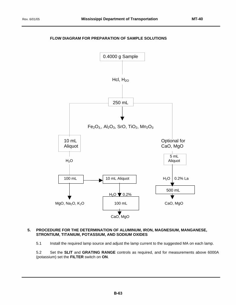
Rev. 6/01/05 Mississippi Department of Transportation MT-40
FLOW DIAGRAM FOR PREPARATION OF SAMPLE SOLUTIONS
0.4000 g Sample
Hcl, H2O
250 mL
Fe2O3,, Al2O3, SrO, TiO2, Mn2O3 10 mL Optional for Aliquot CaO, MgO 5 mL H2O Aliquot 100 mL 10 mL Aliquot H2O 0.2% La
500 mL H2O 0.2% MgO, Na2O, K2O 100 mL CaO, MgO CaO, MgO 5. PROCEDURE FOR THE DETERMINATION OF ALUMINUM, IRON, MAGNESIUM, MANGANESE, STRONTIUM, TITANIUM, POTASSIUM, AND SODIUM OXIDES 5.1 Install the required lamp source and adjust the lamp current to the suggested MA on each lamp. 5.2 Set the SLIT and GRATING RANGE controls as required, and for measurements above 6000A (potassium) set the FILTER switch on ON.
B-63

Rev. 6/01/05 Mississippi Department of Transportation MT-40
5.3 Set the analytical wavelength by rotating the coarse and fine dials of the WAVELENGTH control to obtain a maximum on the ENERGY meter. Keep the ENERGY meter needle near the center of the darker red region by adjusting the GAIN control, avoiding excessive gain which could cause possible damage to the photomultiplier tube.
5.4 Install and align the appropriate burner head. 5.5 Check the waste water receiving tank and make sure that the waste water line from the burner is
at least 125 mm under water and that the 150 mm loop in the line is filled with water. This is necessary to avoid a flashback and ruining the burner assembly.
5.6 Open gas cylinders and air, adjusting to desired pressures as indicated on each pressure gauge. 5.7 Set the fuel and oxidant selector switches as required. 5.8 Depress in turn the FUEL and OXIDANT FLOW CHECK buttons, noting the PRESSURE and
FLOW readings of the respective gauges while the buttons are depressed. If necessary, adjust to obtain recommended settings.
5.9 Set the GASES switch to ON. NOTE: When using N20, set the AIR-OTHER switch to AIR before turning on the gases. After Ignition, flip
the switch to OTHER (N20). An override control inhibits the IGNITER control in the OTHER setting. 5.10 Press and hold the IGNITE button to light the flame. Let burner warm up for five (5) minutes and
adjust flows and pressure setting if necessary. 5.11 Calibration for Concentration Readout. Depress these switches: CONCENTRATION, REPEAT,
10 AVERAGE; set both CURVATURE controls fully counterclockwise. Press the READ switch once after setting the REPEAT switch.
5.12 Peak the ENERGY meter with the FINE WAVELENGTH control. Check burner alignment by
aspirating a solution of Portland cement and adjusting as to locate the area of the flame where the maximum absorption occurs for the element of interest.
IMPORTANT: To help avoid contaminating blank, standard or sample solutions, wipe off the end of the
tubing with a clean tissue each time before inserting it in the solution. Keep the tubing in solvent between determinations. NEVER ASPIRATE SOLUTIONS WITH THE FLAME OFF.
5.13 Aspirate a blank and after three (3) seconds press the AUTO ZERO switch. Continue aspiration until the zero function is completed. 5.14 While aspirating a standard solution, turn the CONCENTRATION control to make the readout
display the concentration value of the standard solution. Fine adjustment may be completed with the CONCENTRATION VERNIER.
5.15 Depress the MANUAL switch, 100 AVERAGE switch and the READ switch to check the
calibration of the standard solution. After calibration, begin aspirating samples and recording their concentration in percentages by depressing the READ switch, checking periodically the zero set and standard concentration, making adjustments when necessary.
5.16 Before shutdown, aspirate distilled water for a few minutes; then set the GASES switch to
SHUTDOWN.
B-64

Rev. 6/01/05 Mississippi Department of Transportation MT-40
6. CALCIUM OXIDE 6.1 Prepare instrument as previously outlined in Subsections 5.1 through 5.13; and after the zero
function is completed in Subsection 5.13, depress the ABSORBANCE, MANUAL, 100 AVERAGE, and READ switches.
6.2 Using four (4) standards spanning the concentration range of the unknown, make a minimum of
four (4) sets of 100 average readings and average to the fourth decimal place; and make either a plot of concentration vs. absorbance or a least squares calculation and determine the percent of concentration of the unknown.
B-65

Rev. 6/01/05 Mississippi Department of Transportation MT-41
MT-41 The Atomic Absorption Method of Analysis of Agricultural Limestone SCOPE: This method of analysis is intended for the determination by atomic absorption spectrophotometry of
the calcium and magnesium carbonate contents of agricultural limestone. A series of solutions prepared from commercial stock standard solutions is utilized for calibration purposes.
1. APPARATUS
1.1 Perkin-Elmer Model 3110 Atomic Absorption Spectrophotometer and a 50 mm short path acetylene burner head.
1.2 Acetylene cylinder and a supply of clean moisture-free compressed air. 1.3 A vent for removing toxic fumes and heat. 1.4 A 500 watt constant voltage transformer. 1.5 A muffle furnace capable of maintaining 1800°F. 1.6 Stock solutions of known concentrations of calcium and magnesium. 1.7 Mortar and pestle. 1.8 No. 100 Sieve. 1.9 Platinum crucible. 1.10 Balance, analytical, capable of weighing 0.1 mg. 1.11 Suitable glassware. 2. REAGENTS 2.1 Hydrochloric Acid, Reagent Grade. 2.2 Lithium Metaborate, Anhydrous, Reagent Grade. 2.3 Lanthanum Solution. Wet 58.65 g of La203, with distilled water. Add 250 mL of concentrated HCl
very slowly until the material is dissolved. Dilute to 1000 mL with distilled water; this provides a 5% Lanthanum solution in 3N HCl.
3. STANDARDS A minimum of six (6) samples spanning the concentration range of the element of interest is required to
construct calibration curves. These standards of known concentrations of the elements of interest are prepared from stock solutions and are run through the instrument to calibrate the digital readout system at the time the sample is ready to be examined.
B-66
Rev. 6/01/05 Mississippi Department of Transportation MT-41
4. SAMPLE PREPARATION 4.1 By use of appropriate sizes of sample splitters, take an aliquot of approximately 25 g. Grind this
sample in a mortar so that it will all pass a 100-mesh sieve. Mix well by shaking in a 250 mL can. Place a portion of this ground and mixed material in a bottle and oven-dry at 105 - 110°C for at least two (2) hours. Now, place the bottle and sample in a desiccator and allow to cool to room temperature.
4.2 Measure approximately 0.1 g of the dried sample to the nearest 0.0001 g into a platinum crucible.
Add approximately 0.6 g of lithium metaborate to the crucible and fuse the mixture in the muffle furnace at 1800°F for fifteen (15) minutes; remove and allow to cool.
4.3 Place a small Teflon stirring bar in the crucible and fill approximately three-fourths full with hot
distilled water and 5 mL of concentrated hydrochloric acid. Place the crucible on a magnetic stirrer-hot plate which is set at low heat and low speed. When solution is complete, proceed to Subsection 4.4.
4.4 Transfer the solution to a 250 mL volumetric flask through a funnel, washing crucible lid, stirring
bar and funnel with hot distilled water. Allow to cool to room temperature and dilute to the mark. 4.5 Pipette 10 mL of the solution into another 250 mL volumetric flask containing 20 mL of 5%
lanthanum solution, and dilute to the mark. 5. PREPARATION OF STANDARDS 5.1 Fuse approximately 0.6 g lithium metaborate in a platinum crucible as described in Subsection 4.2. Dilute as described in Subsections 4.3 and 4.4. 5.2 Add 4 mL of the above lithium metaborate solution and 8 mL of the 5% lanthanum solution to each
of six 100 mL volumetric flasks. From stock standard solutions, add to each of the flasks enough magnesium and calcium to produce the following concentrations after dilution to the mark:
No. 1 No. 2 No. 3 No. 4 No. 5 No. 6 PPM Mg 0.00 0.5 1.00 1.50 2.00 2.50 PPM Ca 6.00 5.00 4.00 3.00 2.00 0.00 6. PROCEDURE 6.1 Set the acetylene line pressure at 8 psi and the air pressure at 30 psi.
6.2 Set the instrumental parameters for the spectrophotometer for the element of interest according to the manufacturer’s recommendations. These parameters are subject to change at the operator's discretion. 6.3 Adjust the monochrometer to isolate the desired resonance line of the element to be determined and peak the resulting signal while keeping the energy meter inside the red zone by use of the gain control.
6.4 Check the waste receiving tank and make certain that the waste line from the burner is at least 6
inches under water and that the 6 inch loop in the line is filled with water. This is necessary.to avoid a flash-back, which may ruin the burner assembly.
6.5 Adjust the flow of gases and light the burner. Let the burner warm up five (5) minutes and readjust
gas flow if necessary. 6.6 Check the resonance line signal for fading and readjust the wavelength control if necessary.
B-67

Rev. 6/01/05 Mississippi Department of Transportation MT-41
6.7 Aspirate the solution containing the highest concentration of the element of interest and adjust the burner height so as to locate the area of the flame where the maximum absorption occurs for the element of interest.
6.8 If absorption exceeds 70%, rotate the burner head to a degree that will bring the percent
absorption within a usable range. 6.9 Either or both of the following methods of data readout may be used at the operator's discretion. 6.9.1 ABSORBANCE METHOD 6.9.1.1 While aspirating the blank solution, press the, ABSORBANCE, AUTO ZERO, 100 AVERAGE, MANUAL and READ switches. 6.9.1.2 Aspirate the blank and standards and record the absorbance of each. Aspirate the unknown and
record the absorbance of each. Aspirate the standards again, the unknowns again, and then the standards for the third time. Average the three absorbance values of each of the standards and the two values for each of the unknowns.
6.9.1.3 Plot on a graph the concentration of the standards versus the absorbance values of the standards.
Determine the PPM concentration of the unknowns from the graph using the absorbance values. 6.9.2 DIRECT CONCENTRATION 6.9.2.1 By using the concentration mode and the curvature correction, concentrations may be displayed directly to the one hundredth of a PPM of the element of interest. 6.9.2.2 Refer to Instructions Manual, Section 2B, 3-5, for concentration readout and curvature correction. 7. CALCULATIONS For the determination of the percent concentration, use the following formula: % Concentration = PPM x Gravimetric Factor x Dilution Factor Mass of Sample x 10 000 For Calcium, = PPM x 2.4973 x 6250 % CaCO3 Mass x 10 000 Magnesium, = PPM x 3.4676 x 6250 % MgC03 Mass x 10 000 Convert the element concentration to the equivalent carbonate value. Convert the MgCO3 concentration to its equivalent CaCO3, concentration, and add these two values of CaCO3 concentration. 8. REPORT Report the percent concentration of CaCO3 to the nearest 0.1%.
B-68

Rev. 6/01/05 Mississippi Department of Transportation MT-53
MT-53 Standard Method of Test for Barbed Wire PURPOSE: To establish a standard method of test for barbed wire. 1. GENERAL This standard operating procedure sets out a test method to determine the requirements of barbed wire as
specified in Subsections 6.2 and 7.3 of ASTM A 121. All other tests will be performed in accordance with the methods set out in ASTM A 121.
2. APPARATUS 2.1 Spring scales graduated to 200 pounds. 2.2 A device to hold a length of 25 feet of wire. 3. TEST PROCEDURE 3.1 Place 25 ft of wire in the device noted in Subsection 2.2 and apply a tension load of 200 lbs. 3.2 Count the number of barbs in the 25 ft length of wire and record as A. 3.3 Count the number of barbs that will spin out of place by twisting the barbs by hand or that will move
laterally more than 3/4 inch and record as B. 3.4 Measure the distance between each of the barbs in the 8 m length of wire and compute the average spacing of the barbs. 3.5 Count the number of bent barbs and record as C. A bent barb is defined as a barb that is bent so that the point will not stick. 3.6 Count the number of barbs that do not have sharp points and record as D. 4. COMPUTATIONS 4.1 Percent of Defective Barbs = B+C+D x 100 A 4.2 The average spacing of the barbs is equal to the sum of the individual spacing divided by the total number of spaces measured.
B-69

Rev. 6/01/05 Mississippi Department of Transportation MT-58
MT-58 Soluable Sulfate Ion in Soils and Water SCOPE: This test method establishes a standard of procedure and equipment for use in determining the water soluble sulfate ion (S04=) in soils and in water. 1. SUMMARY OF METHOD This method describes the indirect determination of water-soluble sulfate by precipitation with standard barium chloride solution and subsequent atomic absorption measurement of the excess barium. 2. APPARATUS 2.1 Spectrophotometer. Atomic Absorption--Perkin-Elmer Model 3110, or equivalent instrument. 2.2 Support apparatus for the operations of the above instrument, gas, air, vent, etc. 2.3 Hot plate. 2.4 Shaker or some other means of agitating the soil sample. 2.5 Centrifuge, high speed. 2.6 Tubes, centrifuge, capable of holding in excess of 25 mL and withstanding 10 000 RPM. 2.7 Balance, analytical, capable of measuring mass within 0.1 mg. 2.8 Oven, drying, capable of maintaining 105 ± 5°C. 2.9 Mortar and pestle or some other means for grinding the soil sample. 2.10 No. 50 Sieve. 2.11 Glassware, assorted, to meet requirements as specified in procedure. 3. REAGENTS 3.1 Barium Chloride Stock Solution. Dissolve 8.8960 g of reagent-grade barium chloride dihydrate, BaCI2 2 H20, in dionized water and dilute to 1 L. This solution contains 5000 ppm barium. 3.2 Sulfate Stock Solution. Dissolve 1.4798 g of dried anhydrous sodium sulfate, Na2 S04, in deionized water and dilute to 1 L. This solution contains 1000 ppm sulfate (S04=) 3.3 Hydrochloric Acid, concentrated reagent grade. 3.4 Methyl Red. 2g methyl red per 1 L of 95% ethyl alcohol.
B-70

Rev. 6/01/05 Mississippi Department of Transportation MT-58
4. STANDARD SOLUTIONS. Standard solutions are prepared either by dilution of the barium stock solution, or by dilutions of the sulfate
stock solution and treating the sulfate standard solutions as described under Sample Preparation. Once linearity of the concentration range is established as few as one standard and blank may be used for direct readout.
5. SAMPLE PREPARATION 5.1 If the soil sample as received has not previously been prepared for analysis, a representative portion of the sample is dried at 105 ± 5°C and ground to pass the No. 50 sieve. 5.2 To 10 g of the prepared soil in a clean plastic bottle, add 100 mL of deionized water and agitate for
fifteen (15) minutes on the small paint shaker. If a less vigorous means of agitation is used, a longer period of time is necessary.
5.3 Centrifuge a portion of the liquid at approximately 10 000 RPM for ten (10) to fifteen (15) minutes
and then pipette a 25 mL aliquot into a 50 mL volumetric flask. To the sample and standard solutions, add concentrated hydrochloric acid until the solution is acid to methyl red and then add one (1) drop in excess. Heat to just below boiling and pipette 4 mL of barium chloride stock solution. Digest a minimum of two (2) hours before cooling. Dilute to volume; mix thoroughly; and allow to settle, preferably overnight.
5.4 Water samples are treated as outlined in the previous subsection, usually without centrifuging. 6. ANALYSIS Determine the barium concentration in the supernatants from the sample and standard solutions using the
standard condition for barium except that a 4-inch single slot burner head with air-acetylene flame should be used for reduced sensitivity.
7. CALCULATION Soils (400 ppm Ba - ppm Ba in diluted samples) x 0.6994 500 = % Soluble S04 Water (400 ppm Ba - ppm in diluted samples) x 2 x 0.6994 = ppm Soluble SO4
B-71

Rev. 4/23/10 Mississippi Department of Transportation MT-59
MT-59 Determination of Loss of Coating of HMA (Boiling Water Test) PURPOSE: This method is intended to provide a rapid test that will give an indication of the resistance of a
bituminous paving mixture to stripping with or without an antistripping additive. The bituminous paving mixture may be either plant-mixed or laboratory-mixed. This test may be performed in the field, District or Central Laboratories. The loss of adhesion of asphalt from the aggregate particles, if any, is determined subjectively by visually examining the proportion of stripped aggregate particles.
1. APPARATUS 1.1 Oven. Capable of maintaining constant temperatures with ± 5°F. 1.2 Balance. Capacity of approximately 2 kilograms or more and sensitive to 1 g or less. 1.3 Burner or Hot Plate. A burner shall be equipped with a ring-stand and a ceramic-centered iron wire
gauze to prevent localized over heating of the beaker. A hot plate shall be properly shielded to uniformly distribute the heat across the surface.
1.4 Beaker. Stainless steel or Pyrex at least 1000 mL capacity. 1.5 Thermometers. Armored glass or dial-type with metal stem, having a temperature range of 50 to 400°F, sensitive to ± 5°CF. 1.6 Stirring Rods. Glass or stainless steel. 1.7 Miscellaneous. Asbestos gloves, pans, beaker tongs, spatula, etc. 1.8 Distilled or deionized water. 2. PREPARATION OF LABORATORY MIXTURES 2.1 PREPARATION OF ANTISTRIPPING ADDITIVE. When the bituminous paving mixture requires the use of
an antistripping additive to prevent stripping, the additive shall be prepared, as follows,depending on the type to be used:
2.1.1 LIQUID ANTISTRIPPING ADDITIVE. When a liquid antistripping additive is to be used, the asphalt
cement in sufficient quantity for the test shall be heated to 149°C in an oven. The selected quantity of additive shall be added based, on percent by mass of the asphalt cement. Immediately mix the contents thoroughly for two (2) minutes using a stainless steel or glass stirring rod. Maintain the treated asphalt cement at 149°C until it is used. If the treated asphalt cement is not used on the same day in which it is prepared, or if it is allowed to cool so that it would require reheating, it shall be discarded.
2.1.2 POWDERED SOLID ANTISTRIPPING ADDITIVE. When a powdered solid antistripping additive is to be
used, the batch of mineral aggregate shall be dried, composited, and heated to 149°C. The selected quantity of additive shall be added to the aggregate based on percent by mass of total aggregate, and the entire mass shall be thoroughly mixed until a uniform distribution of additive has been achieved. Care shall be taken to minimize loss of additive to the atmosphere in the form of dust. After mixing, maintain the treated aggregateat the temperature required for mixing until it is used.
2.2 PREPARATION OF BITUMINOUS PAVING MIXTURE. Prepare approximately 1000 g of the mixture in
accordance with the job-mix formula using the procedure set out in MT-34M. Spread the mixture in a pan and allow to cool completely to room temperature no longer than twenty-four (24) hours.
B-72

Rev. 4/23/10 Mississippi Department of Transportation MT-59
3. PREPARATION OF SAMPLES OF PLANT-PRODUCED MIXTURE 3.1 Obtain a sample of the mixture from a truck using standard sampling techniques. Using a sample
splitter or the quartering method, select approximately 1000 grams of the mixture. If the test sample is not to be tested in the field laboratory, place in a sealed container and transport to the laboratory.
3.2 Allow the sample to cool completely to room temperature. 4. PROCEDURE 4.1 Fill the beaker with distilled or deionized water and bring to a boil on the properly adjusted burner or hot plate. 4.2 Transfer approximately 200 g of the sample into the boiling water and boil for a period of ten (10) minutes. 4.3 Remove from heat, drain off water, empty the contents onto a white paper towel, and allow to dry. 5. DETERMINATION OF STRIPPING 5.1 The extent of stripping is indicated by visually examining the portion of stripped aggregate particles. The stripping is rated subjectively and shall be no more than 5%. 5.2 If the stripping exceeds 5%, a new dosage rate of antistripping additive shall be established using
MT-63. If the mixture did not contain an antistripping additive, an additive shall be incorporated in accordance with MT-63.
B-73

Rev. 6/01/05 Mississippi Department of Transportation MT-61
MT-61 Method of Test for Determining Soil Resistivity
PURPOSE: To establish a standard procedure for determining the minimum resistivity of soil samples. 1. GENERAL The minimum resistivity is defined as the lowest resistivity obtained when running a series of tests on a particular sample. 2. APPARATUS
2.1 Resistivity meter capable of measuring the resistivity from 0-10,000 ohms to within 2% accuracy.
2.2 Soil box calibrated for use with resistivity meter. (See attached drawing) 2.3 Sieve, No. 8 sieve. 2.4 Drying pans. 2.5 Oven, 200° F. 2.6 Balance, 7 kg capacity, sensitive to within 0.1% of sample mass. 2.7 Pulverizing apparatus (mortar and rubber-covered pestle). 2.8 Sample splitter. 3. SAMPLE Soil sample should contain at least 6000 g. 4. PROCEDURE
4.1 The soil sample as received from the field shall be dried thoroughly in the drying apparatus at a temperature not exceeding 60°C. The aggregations of soil particles shall then be broken up in the pulverizing apparatus in such a way as to avoid reducing the natural size of individual particles.
4.2 Screen thoroughly mixed sample through a No. 8 sieve. Only the natural material passing
the No. 8 sieve is to be used for the test. 4.3 Quarter or split 1300 g of material passing a No. 8 sieve. 4.4 Add 150 mL (cc) of distilled water to the 1300 g of soil and thoroughly mix. 4.5 Place the thoroughly mixed soil in the soil box and compact. (Moderate compaction with
the fingers is sufficient.) 4.6 Measure the resistivity of the soil in accordance with the instructions furnished with the
meter.
B-74

Rev. 6/01/05 Mississippi Department of Transportation MT-61
4.7 Remove the soil from the soil box and add 100 additional mL (cc) of distilled water and thoroughly mix.
4.8 Place and compact the remixed soil in the soil box and measure its resistivity. 4.9 Repeat Subsections 4.7 and 4.8 once more. 4.10 If the resistivity of the soil has not followed a trend of high resistivity, low resistivity, and
then an increase in resistivity for the preceding additions of distilled water, continue to add water in 50 mL increments to the soil, mixing, placing, compacting, and measuring resistivity for each increment until the minimum resistivity is obtained.
4.11 Record the test value that is the minimum value of soil resistivity regardless of the moisture
content.
B-75

Rev. 6/01/05 Mississippi Department of Transportation MT-61
4 1/2 “
3 1/4 “
6 1/2 “ 4 1/2 “
1/4
2 “ 7/8 “
NOTE: Stainless Steel Electrodes 20
Material – ¼ “ Plastic
Bottom - 1 Pc. 6 ½ “ x 4 ½ “ x ¼ “ Ends – 2 Pcs. 4 ½ “ x 1 ¾ “ x ¼ “ Sides – 2 Pcs. 6 “ x 1 ¾ “ x ¼ “ Electrodes – 2 Pcs. 20 Ga. Stainless Steel 6 “ x 1 ¾ “ 2 Ea. No. 8-32 = ¾ “ Round Head Stainless Steel Machine Screw With
TYPICAL
SOIL BOX FOR LABORATORY RESISTIVITY DETERMINATION
B-76
Rev. 6/01/05 Mississippi Department of Transportation MT-63
MT-63 Resistance of Bituminous Paving Mixtures to Stripping (Vacuum Saturation Method)
PURPOSE: To establish a standard procedure for determining the need for antistripping additives, the
effectiveness of antistripping additives, and for establishing dosage rates in bituminous paving mixtures.
1. APPLICABLE TEST METHODS 1.1 AASHTO T 166, Bulk Specific Gravity of Compacted Bituminous Mixtures. 1.2 AASHTO T 209, Maximum Specific Gravity of Bituminous Paving Mixtures.
1.3 MT-78, Volumetric Design of Hot Bituminous Paving Mixtures Using the SUPERPAVE Gyratory Compactor.
2. APPARATUS
2.1 In addition to the apparatus set out in the above “Applicable Test Methods,” the following apparatus is required:
2.1.1 Steel Loading Strips for 6-Inch Diameter Test Specimens. Steel loading strips, 0.75 inch
wide, with a concave surface having a radius of curvature equal to the nominal radius of the 6-inch diameter test specimen. The length of the loading strip shall exceed the thickness of the test specimen. The edges of the strips shall be rounded by grinding.
2.1.2 Vacuum chamber, equipped with gauge, capable of withstanding 30 inches of mercury.
The chamber shall be large enough to hold at least two (2) 6-inch specimens submerged in water with space on all sides.
2.1.3 Vacuum pump capable of pulling twenty-nine (29) inches of mercury or more. 2.1.4 Constant temperature water bath at least 8 inches deep and thermostatically controlled so
as to maintain the bath at 77 ± 1.8°F. The tank shall have a false bottom or a shelf for supporting the immersed specimen.
2.1.5 Distilled or deionized water.
3. PREPARATION OF ANTISTRIPPING ADDITIVE
3.1 When the bituminous mixture requires the use of an antistripping additive to prevent stripping, as determined by this test method, the additive shall be prepared as follows, depending on the type to be used:
3.1.1 LIQUID ANTISTRIPPING ADDITIVE. When a liquid antistripping additive is to be used, the
asphalt binder in sufficient quantity for the test shall be heated to 300°F in an oven. The selected quantity of additive shall be added based on percent by mass of the asphalt binder. Immediately mix the contents thoroughly for two minutes using a stainless steel or glass stirring rod. Maintain the treated asphalt binder at 300°F until it is used. If the treated asphalt binder is not used on the same day in which it is prepared, or if it is allowed to cool so that it would require reheating, it shall be discarded.
B-77

Rev. 6/01/05 Mississippi Department of Transportation MT-63
4. PROPORTIONING BITUMINOUS MIXTURES
.4.1 The bituminous mixture shall be proportioned in accordance with the job-mix formula from samples of the actual component materials to be incorporated in the work. The mixture shall be proportioned in batches as follows:
4.1.2 Dry each batch of blended mineral aggregate to a constant weight. Add 2.5 ± 0.5 percent
water plus the percent of water absorption for the blend as determined by AASHTO T84 and T85 to each aggregate batch. Mix the batch so that the water is uniformly distributed. The damp aggregate should be allowed to sit for approximately four hours prior to introducing the hydrated lime. Add 1 % hydrated lime to the aggregate as a percent by dry weight of total aggregate. Mix the combined materials until a uniform distribution of lime has been achieved. Care shall be taken to minimize the loss of lime to the atmosphere in the form of dust.
4.1.3 One batch shall be prepared for the determination of maximum specific gravity in
accordance with AASHTO T 209. If the maximum gravity test was previously performed during the development of the job-mix formula using the same material samples, this step may be omitted.
4.1.4 One batch for each laboratory compaction operation. Approximately 3800 grams
are required for each compacted 6-inch diameter by 3.75-inch high test specimen. A minimum of four(4) 6-inch diameter test specimens is required for performance of this test.
5. PREPARATION OF LABORATORY COMPACTED SPECIMEN 5.1 Preparation of 6-Inch Diameter Test Specimens.
5.1.1 Mixing and compaction shall be performed in accordance with MT-78 with the following exceptions:
5.1.1.1 Compact four(4) specimens to 7.0 ± 1 percent air voids or other void level expected in the
field. This level of voids can be obtained by adjusting the number of gyrations of the Gyratory Compactor or by setting the compactor to produce 3.75-inch high specimens and adjusting the mix weight to get the proper air void level. The exact procedure must be determined experimentally for each mixture.
5.1.1.2 Cool specimens in the mold for approximately 15 minutes in front of a fan blowing room
temperature air, extract the samples from molds, and continue curing at room temperature at least overnight not to exceed twenty-four (24) hours.
6. DENSITY AND VOID DETERMINATION
6.1 Determine the maximum specific gravity in accordance with AASHTO T 209. 6.2 Determine the bulk specific gravity of each of the compacted specimens in accordance
with AASHTO T 166, Method A. Record the volume of the specimens in cubic centimeters. The term (B-C) in T 166 Method A is the volume of the specimen in cubic centimeters.
B-78

Rev. 6/01/05 Mississippi Department of Transportation MT-63
6.3 Calculate the percent air voids in each of the compacted specimens by the following formula:
% Air Voids = 100 ⎥⎦⎤
⎢⎣⎡ −
mm
mb
GG1
Where: Gmb = Bulk Specific Gravity Gmm = Maximum Specific Gravity 6.4 Calculate the volume of air voids (Va) in cubic centimeters for each of the compacted
specimens according to the following formula: Va = Volume of Specimen, cc x % Air Voids 100 7. CONDITIONING OF COMPACTED SPECIMENS
7.1 Sort the specimens into two subsets (2 - 6 inch diameter specimens per subset) so that the average air voids of the two subsets are approximately equal. One subset is to be stored at room temperature until the indirect tensile strength is to be determined. The other subset is to be subjected to moisture-conditioning in an attempt to induce moisture-related damage (stripping).
7.2 Place the subset to be moisture-conditioned in the vacuum chamber, fill with distilled or
deionized water at room temperature until the specimens are completely submerged, and saturate under vacuum until the voids are 55 to 80 percent filled as follows:
7.2.1 Saturate by applying a partial vacuum such as 20 inches of mercury for five (5) minutes.
NOTE: Experience with partial vacuum at room temperature indicates that the degree of saturation is very sensitive to the magnitude of the vacuum and practically independent of the duration. The level of vacuum needed appears to be different for different mixtures.
7.2.2 Remove the specimens from the vacuum chamber and determine the saturated surface
dry mass in air in accordance with AASHTO T 166, Method A. 7.2.3 Calculate the volume of absorbed water (Vws) in cubic centimeters by subtracting the mass
in air of the specimen determined in Subsection 6.2 from the saturated surface-dried mass in air determined in Subsection 7.2.2.
7.2.4 Calculate the degree of saturation (Ws) from the following formula.
Ws = 100xVV
a
ws
Where, Ws = Degree of saturation after vacuum, percent Vws = Volume of absorbed water after vacuum, cc Va = Volume of air voids from Subsection 6.4, cc.
If the degree of saturation is between 55% and 80%, proceed to Subsection 7.3.
If the degree of saturation is less than 55%, place the specimen back in the vacuum chamber and repeat the procedure beginning with Subsection 7.2, but at a slightly higher vacuum. Repeat the procedure until the required degree of saturation is obtained. If the
B-79

Rev. 6/01/05 Mississippi Department of Transportation MT-63
degree of saturation is more than 80%, the specimen has been damaged and must be discarded, in which case a new specimen must be molded and the process repeated.
7.3 Place the vacuum saturated specimens in a distilled or deionized water bath (unagitated)
at 140°F and moisture condition for twenty-four (24) hours. 7.4 Remove the specimens from the 140°F water bath and place them in the 77°F water bath
for two (2) hours + 30 minutes. 7.5 Remove the moisture-conditioned specimens from the 77°F water bath and determine the
bulk specific gravity in accordance with AASHTO T 166, Method A. Record the volume of the specimens in cubic centimeters. The term (B-C) in T 166, Method A, is the volume of the specimens in cubic centimeters.
7.6 Calculate the volume of absorbed water (Vwm) in cubic centimeters by subtracting the mass
in air of the specimen determined in Subsection 6.2 from the saturated surface dried mass in air determined in Subsection 7.5.
7.7 Calculate the degree of saturation (Wm) of the moisture-conditioned specimens from the
following formula.
Wm = 100xV
Wa
wm
Where, Wm = degree of saturation following moisture conditioning, percent Vwm = volume of absorbed water following moisture conditioning, cc Va = volume of air voids from Subsection 6.4, cc NOTE: Degree of saturation exceeding 80 percent is acceptable in this step.
7.8 Measure the diameter of the moisture-conditioned specimens to the nearest 0.01-inch
using calipers. 7.9 Adjust the temperature of the unconditioned specimens in the subset which has been
curing at room temperature by placing them in the 77°F water bath for thirty (30) minutes + 5 minutes.
8. INDIRECT TENSILE STRENGTH
8.1 Determine the indirect tensile strength of each specimen at 77°F from both the unconditioned subset and the conditioned subset.
8.1.1 Place the specimen on edge and centered with the breaking head of the testing machine.
Center the loading strip on top of the specimen so that the concave surface fits the curvature of the specimen circumference.
8.1.2 Apply diametrical load at the rate of 2 inches per minute until the maximum load is
reached. Record the maximum load (P) in pounds (the Marshall breaking press has a loading rate of 2 inches per minute).
8.1.3 Continue loading until specimen can be separated at the failure plane for visual
examination of the degree of particle stripping. 8.1.4 Calculate the indirect tensile strength from the following formula:
B-80

Rev. 6/01/05 Mississippi Department of Transportation MT-63
St = V
PD1935.8
Where, St = Indirect tensile strength, psi P = Maximum load at failure, pounds D = Diameter of specimen in inches. The diameter of the unconditioned specimen
equals the inside diameter of the mold in which the specimen was compacted. The diameter of the moisture-conditioned specimen was determined by measurement in Subsection 7.8.
V = Volume of specimen as tested in tension in cubic centimeters. See Subsection 6.2
for volume of unconditioned specimen and Subsection 7.5 for the volume of the moisture-conditioned specimen.
9. TENSILE STRENGTH RATIO
9.1 Calculate the average indirect tensile strength of the unconditioned subset (Stu). 9.2 Calculate the average indirect tensile strength of the moisture-conditioned subset (Stm). 9.3 Determine the tensile strength ratio from the following formula:
TSR = 100xSS
tu
tm
Where: TSR = Tensile strength ratio, percent Stm = Average indirect tensile strength of the moisture-conditioned specimens, psi. Stu = Average indirect tensile strength of the unconditioned specimens, psi. 10. DEGREE OF PARTICLE STRIPPING
10.1 After testing under Subsection 8.1.3, separate each moisture-conditioned specimen at the failure plane. Examine each exposed face for loss of asphalt from the aggregate surfaces.
10.2 Estimate subjectively the proportion of stripped aggregate particles and record in percent.
11. DETERMINING THE NEED FOR ANTISTRIPPING ADDITIVE
11.1 If the results of this test on the bituminous paving mixtures without antistripping additive meets all of the specification requirements, the mixture is considered to be sufficiently resistant to stripping; therefore, it will not require the use of an antistripping additive.
12. DETERMINING THE EFFECTIVENESS OF ANTISTRIPPING ADDITIVE AND ESTABLISHING
DOSAGE RATES
12.1 In order to determine the effectiveness of the antistripping additive and determine the dosage rate, the bituminous paving mixture must be tested with and without the additive proposed for use in the mixture.
B-81

Rev. 6/01/05 Mississippi Department of Transportation MT-63
12.2 To be approved, the type additive proposed for use must result in the bituminous paving mixture’s conformance to all of the specification requirements. Also, the dosage rate shall be the lowest necessary (Manufacturer's Recommended Rate or higher) to result in the bituminous paving mixtures conformance to all of the specification requirements.
12.3 The average indirect tensile strength of the moisture-conditioned specimens containing the
additive must be greater than the average indirect tensile strength of the moisture-conditioned specimens without the additive.
12.4 The dosage rate selected in the laboratory shall be tentative until tests have been
performed on the plant-produced mixture. 13. REPORT 13.1 Average degree of saturation after application of vacuum. 13.2 Average degree of saturation after moisture-conditioning.
13.3 Average indirect tensile strength without antistripping additive of unconditioned specimens and of moisture-conditioned specimens.
13.4 Average indirect tensile strength with antistripping additive of unconditioned specimens
and of moisture-conditioned specimens. 13.5 Tensile Strength Ratio (TSR) with and without antistripping additive. 13.6 Results of estimated stripping observed when specimen fractures. 13.7 Type antistripping additive and dosage rate required. If no additive is required, so indicate.
14. JOB CONTROL ACCEPTANCE TESTING
14.1 Job control acceptance testing for resistance of plant-produced mixtures to stripping will be performed in accordance with Sections 1 through 13 of this S.O.P. except for the following modifications:
14.1.1 Subsection 5.2.1.2. Curing will not be required overnight. Cool in front of a fan at room
temperature a minimum of three (3) hours + 30 minutes. 14.1.2 Subsections 7.2 and 7.3. Drinking water may be used.
B-82

Rev. 6/01/05 Mississippi Department of Transportation MT-64
MT-64 Asphalt Retention and Change in Area of Geotextile Pavement Fabric PURPOSE: To establish a standard method of test for asphalt retention and change in area of geotextile
pavement fabric. 1. APPARATUS 1.1 Die, 100 mm by 200 mm. 1.2 Oven capable of maintaining a temperature of 135 ± 2°C. 1.3 Balance meeting requirements of AASHTO Designation: M 231, Class D. 1.4 Rack for hanging test specimens. 1.5 Hot plate or oil bath for heating mineral spirits.
1.6 Pans suitable for use in submerging the test specimens in asphalt and washing the test specimens.
2. SAMPLE PREPARATION
2.1 Cut three (3) test specimens at random using the 100 mm by 200 mm die. Test specimens shall be free of defects which are obviously caused by handling of the test sample.
3. PROCEDURE 3.1 Determine mass of the test specimens to nearest 0.1 g.
3.2 Submerge test specimens in asphalt cement at a temperature of 135 ± 2°C. Asphalt cement shall be of same grade that will be used with the fabric on the roadway.
3.3 Maintain submerged test specimens at a temperature of 135 ± 2°C for thirty (30} minutes in oven. 3.4 Remove test specimens from asphalt cement, hang on rack and drain at a temperature of 135 ±
2°C for thirty (30) minutes. 3.5 Remove the test specimens from the oven and allow to drain at a temperature of 24 ± 3°C for
one (1) hour. 3.6 Determine mass of the coated test specimens to nearest 0.1 g and determine the mass of
asphalt cement retained. 3.7 Submerge test specimens in mineral spirits at a temperature of 43 ± 3°C for thirty (30) minutes.
Fresh containers of mineral spirits may be alternated as necessary to effect the removal of the asphalt cement. Maintain temperature of mineral spirits with hot plate.
3.8 Remove test specimens from mineral spirits, blot with paper towels, and air dry to constant mass. 3.9 Measure test specimens to nearest 0.000 25 m and compute area in square meters.
B-83

Rev. 6/01/05 Mississippi Department of Transportation MT-64
4. CALCULATION 4.1 Asphalt Retention R = W A R = Asphalt cement retention in grams per square meter W = Mass in grams of asphalt retained in specimen (Subsection 3.6) A = Area of test specimen in square meters (Subsection 3.9) 4.2 Percent Change in Area C = 100 - 5000 A C = Change in area in percent A = Area of tested specimen in square meters (Subsection 3.9) NOTE: Based on test specimen of 100 mm. x 200 mm. 5. REPORT 5.1 Report the average asphalt retention to the nearest 3 g. per m2. 5.2 Report the average change in area to the nearest percent.
B-84

Rev. 6/01/05 Mississippi Department of Transportation MT-70
MT-70 Reflective Intensity of Highway Traffic Striping Materials Using a Mirolux 12 Reflectometer SCOPE: This method covers the measurement of the retroreflective properties of traffic-striping systems using a Mirolux 12 Retroreflectometer. 1. APPARATUS 1.1 Mirolux 12 Retroreflectometer. 1.2 Ambient Light Shield. A strip of cloth or other suitable shield. 2. CALIBRATION 2.1 Calibrate the Mirolux 12 in accordance with manufacturer's instructions. 3. PROCEDURE
3.1 Position the Mirolux 12 on the surface to be read, making sure that all three (3) supports are in contact with surface.
3.2 Position the light shield around the front half of the Mirolux12, blocking out all outside light. 3.3 With digital display reading zeroed, turn on light and allow the reading to stabilize. (Reading must
be manufacturer's assigned calibration number.) Gently pull out the calibration plate knob to open the shutter. Record the reading for the selected spot as indicated. Turn light off and close shutter by returning knob to original position. To check reading, repeat procedure before changing position of Mirolux 12.
3.4 Take readings at three (3) selected locations on the 5-foot test sample. No reading is to be taken
within 6 inches of either end or on an obviously damaged part of the sample. Average the three (3) readings. The resulting average value is the reflective intensity for the particular lot of material represented by the sample.
4. REPORTING
4.1 Report the reflective intensity in millicandclas per square meter per meter candela at an illumination angle of 86 1/2° and an observation angle of 1 1/2°.
B-85

Rev. 6/01/05 Mississippi Department of Transportation MT-71
MT-71 Cross-Calibration of Troxler Asphalt Content Gauges, Model 3241 PURPOSE: To establish a standard procedure for cross-calibration of Troxler Asphalt Content Gauges,Model
3241, by use of Standard and Background Counts of a Master Gauge and Field Gauges. (This procedure does not replace the initial field calibration (MT-6M) of Asphalt Content Gauges.)
1. SIGNIFICANCE OF USE
1.1 Reduce the time delay problems encountered in the replacement of malfunctioning asphalt content field gauges by eliminating, in most cases, the necessity of field calibration (MT-6) of replacement gauges for the particular job-mix formula being used.
1.2 Provide the Department with the means of checking the asphalt content of a particular job-mix
through the District and/or Central Laboratory. 2. PREPARATION OF CROSS-CALIBRATION SPECIMENS
2.1 Prepare six (6) specimens in accordance with the gauge instruction manual. The specimens must be prepared from the same aggregate blend and asphalt cement and at the same mass within ± 1 g. Starting slightly below the minimum of 4.0%, vary the bitumen content of the specimens at intervals of 1%.
2.2 Seal the specimens with a suitable moisture resistance material such as fiber glass cloth and
epoxy. 3. READING OF MASTER AND FIELD GAUGES
3.1 GENERAL 3.1.1 The asphalt content gauge in the Central Laboratory will be the Master Gauge. However, when a
field gauge must be replaced, this particular field gauge will be the master gauge for the purpose of cross-calibrating the replacement gauge.
3.1.2 All gauges are to be read in the location of intended use if possible. 3.1.3 All gauges are to be read every twenty-four (24) months with freshly prepared cross-calibration
specimens. 3.1.4 Clean inside of gauge and remove all objects that may interfere with readings, such as another
nuclear gauge, asphalt, etc., from the general vicinity of the gauge before taking readings. 3.2 Procedure for reading gauges using cross-calibration specimens. 3.2.1 Perform Statistical Stability Test (STAT) in accordance with the gauge instruction manual. 3.2.2 Take a sixteen (16) minute background count in accordance with the gauge instruction manual,
and record result. 3.2.3 Using the six (6) prepared cross-calibration specimens, take a sixteen (16) minute standard count
of each specimen in accordance with the gauge instruction manual ,and record results. 3.2.4 Record data for each gauge: Model; Serial Number; Contractor; Location; Date; any pertinent
remarks.
B-86

Rev. 6/01/05 Mississippi Department of Transportation MT-71
4. PROCEDURE FOR CROSS-CALIBRATION OF REPLACEMENT GAUGE
4.1 Replacement gauge and the gauge to be replaced must have current record of background and standard counts as set out in Subsection 3.2.
4.2 Provide the Central Laboratory with the following information: serial number of the replacement
gauge; serial number and background count at time of calibration of the gauge to be replaced; project number, MDOT lab number and calibration slope and intercept for the particular mix design being used.
4.3 By use of Troxler's 3241 Model Transfer Program VI. 0011989, determine new calibration slope and intercept values for replacement gauge.
5. REPORT Report new calibration slope and intercept values for replacement gauge. 6. COST OF CROSS-CALIBRATION SERVICE Cost of cross-calibration service per gauge per mix design will be in accordance with the unit price set forth
in S.O.P. No. TMD-20-09-00-000. This service is available to contractors performing work on MDOT projects at the current unit price upon request from the contractor.
B-87

Rev. 6/01/05 Mississippi Department of Transportation MT-73
MT-73 Method of Tests for Bituminous Adhesives (Standard Type) PURPOSE: To establish standard methods of tests for the various required characteristics for bituminous adhesives used in bonding pavement markers to the roadway surface. 1. BITUMINOUS ADHESIVE PROPERTIES Tests for determining the properties of bituminous adhesive shall be performed in accordance with the following methods: 1.1 SOFTENING POINT. ASTM D 36. 1.2 PENETRATION AT 25°C. ASTM D 5.
1.3 FLOW. Determine the flow in accordance with ASTM D 3407, except that the oven temperature shall be 158 ± 2°F and sample preparation shall be according to Subsection 7.1 of ASTM D 5.
1.4 HEAT STABILITY FLOW. Determine the heat stability flow in accordance with Subsection 1.3 of this
test method, except that 1000 g of adhesive shall be placed in a covered liter can, heated to 425°F and maintained at this temperature for four (4) hours prior to preparing the sample panel.
1.5 VISCOSITY, 400°F, POISES. Determine the viscosity in accordance with ASTM D 3236 using a
spindle speed of 10 rpm. The adhesive shall be heated to approximately 410°C and allowed to cool. The viscosity shall be determined at 400 ± 1°F.
1.6 FLASH POINT, C.O.C., °F, ASTM D 92.
2. ASPHALT PROPERTIES Determine the properties of the base asphalt on the filler-free material obtained from the extraction and Abson recovery process, as follows:
2.1 EXTRACTION AND ABSON RECOVERY 2.1.1 Heat the adhesive just to the point where it will easily flow and then transfer 125 to 150 g into 400
mL of trichloroethylene having a temperature of 125 to 150°F. Thoroughly stir the mixture to dissolve the asphalt. Decant the trichloroethylene-asphalt solution.
2.1.2 Recover the asphalt from the decanted solution in accordance with ASTM D 1856, modified as
follows: 2.1.2.1 The extraction method of ASTM D 2712 shall not apply, and there shall be no filtration of the
solvent-asphalt mixture. 2.1.2.2 Centrifuge the solution for at least thirty (30) minutes at 770 times gravity in a batch centrifuge.
Decant this solution into the distillation flask, taking care not to include any filler sediment. 2.1.2.3 Apply heat and bubble carbon dioxide slowly to bring the solution temperature to 300°F. At this
point, increase the carbon dioxide flow to a rate of 800 to 900 mL per minute. Maintain the solution temperature at 320 to 325°F with this carbon dioxide flow rate for at least twenty (20) minutes and until the trichloroethylene vapors have been completely removed from the distillation flask.
B-88

Rev. 6/01/05 Mississippi Department of Transportation MT-73
2.1.2.4 Repeat the above extraction-recovery process until sufficient asphalt is obtained for performance of all test properties. The recovered asphalt shall be used to determine penetration, viscosity and viscosity ratio as set out in Subsections 2.2, 2.3 and 2.4 of this test method.
2.2 PENETRATION, 100 G, 5 SEC, 77°F, ASTM D 5. 2.3 VISCOSITY, 275°F, POISES, ASTM D 2171. 2.4 VISCOSITY RATIO, 275°F. Determine the 275°F viscosity ratio by comparing the 275°F viscosity of
the asphalt before and after the Thin-Film Oven Test, ASTM D 1754. Determine the specific gravity by the pycnometer method as set out in ASTM D 70 for use in the Thin-Film Oven Test. Calculate the 275°F viscosity ratio by dividing the viscosity at 275°F after the Thin-Film Oven Test by the viscosity at 275°F prior to the Thin-Film Oven Test.
3. FILLER PROPERTIES Determine the properties of the filler obtained from the filler separation technique as follows: 3.1 FILLER SEPARATION TECHNIQUE.
3.1.1 Measure 10.00 ± 0.01 g of the solid bituminous adhesive into a certrifuge flask having a volume of approximately 100 mL such as that specified in ASTM D 1796. Add 50 mL of 1,1,1-trichloroethane to the adhesive, which should be broken up into small pieces in order to speed the dissolution process. Swirl or stir with a fine rod, taking care not to lose any solids. Place the sample flask in a balanced centrifuge and spin for ten (10) minutes using a minimum relative centrifugal force of 150 (as determined in Section 6 of ASTM D 1796). Remove the sample flask and decant the solvent, taking care not to lose any solids. Repeat the application of solvent and centrifuging until the solvent becomes clear and the filler is visually free of asphalt. Filtration of the decanted solvent may be performed to verify there is no loss of filter. Dry the filler at 160 ± 5°F to remove solvent and determine the mass of the resulting filler.
3.1.2 Determine the filler content and the filler fineness in accordance with Subsections 3.2 and 3.3 of this test method.
3.2. FILLER CONTENT. From the masses obtained in Subsection 3.1.1, calculate the filler content as
follows: Filler Content, % by mass = (Mass of Dried Filler, g) * (100) Original Adhesive Mass, g
3.3. FILLER FINENESS. The dried filler obtained from separation in Subsection 3.1.1 shall be used in determining the filler fineness. Determine filler fineness in accordance with ASTM C 430 using sieve numbers 100, 200, and 325. This method is to be modified by the use of a water-soluble non-ionic wetting agent, such as Triton X-100, to aid the wetting action. Concentration of the surfactant solution shall be approximately 1% by mass. The 1 g dry sample shall be thoroughly wetted in the surfactant solution and allowed to soak for thirty (30) minutes. The filler shall be transferred completely into the sieve cup and water-spray applied for two (2) minutes. Surfactant solution may be added as needed and physical means used to disperse any clumped particles. The sample shall then be dried and handled as directed in ASTM C 430.
B-89

Rev. 6/01/05 Mississippi Department of Transportation MT-74
MT-74 Determination of Pavement Smoothness Using a Profilograph PURPOSE: To establish a standard procedure for determining pavement smoothness by use of a Profilograph. 1. APPARATUS
1.1 PROFILOGRAPH. Shall consist of a frame at least 7.5 m in length supported upon multiple wheels having no common axle. The profilograph must have at least twelve (12) reference platform wheels. The axes of these wheels shall not be uniformly spaced but be at least 0.3 m apart so no two wheels cross the same bump at the same time. The sensing mechanism located at the mid-frame may consist of a single bicycle-type wheel or a dual-wheel assembly consisting of either a bicycle-type (pneumatic tire) or solid rubber tire vertical sensing wheel and a separate bicycle-type (pneumatic tire) longitudinal sensing wheel. The wheel(s) shall be of such circumference(s) to produce a profilogram recorded on a scale of 1 (one) meter equal to 300 meters longitudinally and one (1) millimeter equal to one (1) millimeter, or full scale, vertically. Motive power is to be provided manually or by the use of propulsion unit attached to the center assembly.
1.2 BLANKING BAND. A plastic scale 40 mm wide and 500 mm long representing a pavement length of
150 m at a scale of 1 to 300. Near the center of the scale is an opaque band 5 mm wide extending the entire length of the scale. On either side of the band are parallel scribed lines 2.5 mm apart. These lines serve as a convenient scale to measure scallops, deviations or excursion, of the graph above or below the blanking band.
1.3 BUMP TEMPLATE. A thin strip of plastic having a line 25 mm long scribed on one face with a small
hole or scribed mark at both ends of the line. The template shall have a slot parallel to the scribed line located at a distance equal to the limiting value for acceptance smoothness (7.5 mm for concrete and 10.0 mm for asphalt when measured from a chord length of 7.5 m or less - see Figure 1).
2. OPERATION OF PROFILOGRAPH
2.1 OPERATIONS. The profilograph shall be moved at a speed no greater than 5 km per hour so as to
eliminate as much bounce as possible. Check tire roundness to eliminate repetitive errors. Surface irregularities in new tires and those that develop through wear shall be removed by grinding. Air pressure in the tires shall be maintained at a constant level and shall be checked daily.
2.2 CALIBRATION. Calibration of the profilograph shall be checked monthly. The horizontal scale can
be checked by running a known distance and scaling the result on the profilogram. If the scale is off more than 0.5%, the manufacturer's adjustment procedure shall be followed to correct the scaling. The vertical scale is checked by putting a board of known thickness under the profile wheel and again scaling the result on the profilogram. If the scale is off, the cause of the incorrect height shall be determined and corrected.
3. RUNNING PROFILES
3.1 The profile is recorded from the vertical movement of a sensing wheel attached at the mid-point of the profilograph and is in reference to the mean elevation of the points of contact with the road surface established by the support wheels.
3.2 A profilogram is recorded on a scale of one meter equal to 300 meters longitudinally and one (1)
mm equal to one (1) mm, or full scale, vertically.
B-90

Rev. 6/01/05 Mississippi Department of Transportation MT-74
3.3 All profilograms will be made in accordance with contract specifications. 3.4 The profiles for each section of pavement shall be positioned on the profilogram so that the
stationing is coincidental. This will help determine if the high points and depressions extend across the entire pavement width and will permit profile index comparison of adjacent lanes.
3.5 The following information shall be marked and/or labeled on the profilogram during testing for ease
in evaluation. 3.5.1 Location (which traffic lane and wheel path). 3.5.2 Beginning and ending station of the profile. 3.5.3 Station numbers and other road items of known location. 3.5.4 Construction joints, significant cracks, damaged areas, etc.
4. DETERMINATION OF PROFILE INDEX
4.1 METHOD OF COUNTING 4.1.1 Place the blanking band over the profile in such a way as to "blank out" as much of the profile as
possible. When this is done, scallops above and below the blanking band usually will be approximately balanced. (See Figure 2)
4.1.2 The profile trace will move from a generally horizontal position when going around super-elevated
curves making it impossible to blank out the central portion of the trace without shifting the scale. When such conditions occur, the profile will be broken into short sections and the blanking band repositioned on each section while counting as shown in the upper part of Figure 1.
4.1.3 Starting at the right end of the scale, measure and total the height of all the scallops appearing
both above and below the blanking band, measuring each scallop to the nearest 1.25 mm or half the distance between the parallel scribed lines on the blanking band scale. Write this total on the profile sheet near the left end of the scale together with a small mark to align the scale when moving to the next section. Short portions of the profile line may be visible outside the blanking band but unless they project 0.75 mm or more and extend longitudinally for 0.60 m or more, they are not to be included in the count. (See Figure 2 for illustration of these special conditions.)
4.1.4 When scallops occurring in the first 0.15 km are totaled, slide the scale of the left, aligning the right
end of the scale with the small mark previously made, and proceed with the counting in the same manner. The last section counted may or may not be an even 0.15 km. If not, its length should be scaled to determine its length in kilometers. An example follows:
Section Length Counts (km) (Number of Lines from Blanking Band) 0.15 5.0 0.15 4.0
B-91

Rev. 6/01/05 Mississippi Department of Transportation MT-74
0.15 3.5 (110 m) 0.11 2.0 Total 0.56 14.5
4.1.5 The profile index is determined as millimeters per kilometer in excess of the 5 mm blanking band but is simply called the profile index. The procedure for converting counts of profile index is as set out below.
4.1.6 Using the figures from the above example:
Length = 0.56 km, total count = 14.5 counts Profile Index = (1 km/length of profiles in km) X total counts X 2.5 Profile Index = (1/0.56) X 14.5 X 2.5 = 64.7 (NOTE: The formula uses the count as the unit of measurement and then converts it to millimeters.)
4.1.7 The profile index is thus determined for the profile of any line called for in the specifications. 4.2 DAILY AVERAGE PROFILE INDEX. The pavement surface is to be divided into sections that represent
continuous placement. A section is to terminate at a day's work joint, a bridge or other interruption. Long sections placed without interruption are to be separated arbitrarily into segments of 0.15 km, with the remaining shorter section also considered a segment. The last 5 m of a segment ending at the day's work joint cannot be profiled until the adjoining pavement is placed. Therefore, the 5 m portion is to be included in the profilogram of the subsequent day's production. Said portion is to be included in the profilogram only when the Contractor is responsible for the adjoining surface. A profilogram is to be made for each continuous section of 15 m or more.
4.2.1 When averaging profile indexes to obtain an average for the day, the average of each section must
be "weighted" according to its length. 5. DETERMINATION OF HIGH POINTS OR DIPS
5.1 To locate the bumps or dips requiring corrective action, place the bump template at each
prominent peak or high point on the profile so that the small holes or scribe marks at each end of the scribed line intersect the profile to form a chord across the base of the peak or high point. The line of the template need not be horizontal. With a sharp pencil draw a line using the narrow slot in the template as a guide. Any portion of the profile extending above this line will indicate the approximate length and height of the deviation in excess of the specified value.
5.2 There may be instances where the base of the high point is less than 25 mm (7.5 m). In such
cases, a shorter chord length must be used in making the scribed line on the template tangent to the profile at the low points. When the distance between prominent low points is greater than 7.5 m (25 mm), make the ends of the scribed line intersect the profile with the template in horizontal position. The baseline for measuring the height of bumps should be as near 7.5 m (25 mm) as possible, but in no case shall it exceed this value. A few examples of the procedure are shown in the lower portion of Figure 1.
6. REPORT 6.1 Profile Index to the nearest mm/km. 6.2 Daily Average Profile Index to the nearest mm/km when applicable. 6.3 Location of high points or dips that require corrective action.
B-92

Rev. 6/01/05 Mississippi Department of Transportation MT-75
MT-75 Testing of Glass Beads PURPOSE: This method sets out procedures for the testing of glass beads. 1. CLASS A (STANDARD). Tests shall be in accordance with requirements of AASHTO M 247. 2. CLASS B (HIGH-VISIBILITY). Tests for gradation, refractive index, embedment coating, and roundness and angular particle concentrations shall be as follows: 2.1 Gradation. In accordance with ASTM D 1214. 2.2 Refractive Index. By the liquid immersion method (Becke Line Method or equal) at a temperature of 25 ± 5°C (77° ± 9°F). 2.3 Embedment Coating. In accordance with following procedure: 2.3.1 Apparatus and Reagents: Graduate Cylinder (50 mL) Acetone - Reagent Grade Dansyl Chloride - 98% Scale - Analytical balance (4 place) Darkened Glass Container (that can be sealed tightly) Rubber Gloves (long sleeves) Safety Glasses or Goggles Medicine Dropper Glass Filter Paper (4 inch diameter) Small Aluminum Dishes for measuring mass 2-inch Buchner Funnel and Suction Flasks 2-inch diameter Filter Paper (Whatman # 1) Vacuum Pump Ultraviolet Light Source - Intensity 7 000 uw/cm2
(CAUTION: Dansyl Chloride is a hazardous compound. Do not handle without protective gloves and safety glasses or goggles. Do not get onto skin.)
2.3.2 PREPARATION OF DANSYL CHLORIDE SOLUTION
Prepare a solution by weighing 0.2 g of Dansyl Chloride and dissolving it in 25 mL of acetone. This solution can be used for several tests during the day but must be kept refrigerated in a dark, tightly closed container between uses. Make a fresh solution daily.
2.3.3 PROCEDURE
2.3.3.1 Set drying oven to 60°C. Turn on the ultraviolet light. 2.3.3.2 Measure two (2) samples of beads of 10 g each. Place the sample to be evaluated in an aluminum
dish. Retain the other sample for a fluorescence observation comparison. 2.3.3.3 Place a 2-inch diameter filter paper into the Buchner funnel and attach to the suction flask. 2.3.3.4 Put the beads in the Buchner funnel and saturate the sample with the Dansyl Chloride solution
using a medicine dropper. Let solution and sample stand for thirty (30) seconds.
B-93

Rev. 6/01/05 Mississippi Department of Transportation MT-75
2.3.3.5 Place the saturated beads into an aluminum dish and dry in oven at 60°C for 15-20 minutes.
Beads will be yellow and agglomerated. Do not let the Dansyl Chloride solution char. (Properly discard the used filter paper because of the toxicity of the Dansyl Chloride.)
2.3.3.6 Remove sample from the oven and place the glass beads in the Buchner funnel with new filter
paper. Rinse the beads with 100 mL of acetone. Use the suction during this step. All yellow must be removed from the beads.
2.3.3.7 Remove the beads from the funnel and place into a new aluminum tray. Allow the beads to dry in
the oven for five (5) to ten (10) minutes until free flowing. 2.3.3.8 Remove the beads from the oven and place on glass filter paper. If beads are agglomerated,
break them up with a spatula. 2.3.3.9 Inspect the treated sample under the ultraviolet light, in a darkened room. 2.3.4 OBSERVATIONS 2.3.4.1 Embedment-coated beads will emit a yellow-green fluorescence. 2.3.4.2 If additional fluorescence is observed when compared with the original untreated sample, the lot is
accepted. If no additional fluorescence is observed, the test should be rerun using a new 10 g sample of beads and a fresh solution of Dansyl Choride.
2.3.4.3 If no additional fluorescence is observed on the new sample of beads, the material is not properly
coated and the lot is rejected. If additional fluorescence is observed, the lot is accepted. 2.4 ROUNDNESS AND ANGULAR PARTICLE CONCENTRATIONS. (A round particle is defined as a spherical or
fundamentally oval bead with an aspect ration of 1.2:1 or less and having no other particles adhered to the parent bead.) in accordance with the following procedure:
2.4.1 APPARATUS
Bell & Howell Microfiche Reader, Model R905, or equivalent, with 20 mm lens Transparencies for +14, +16, +18, +20, and +35 mesh spheres defining a 1.2:1 aspect ration 1/1 mini-splitter Clear, transparent tape Syringe (3 CC) with a 23-gauge needle Microscope slide Cooking oil - Wesson Oil, or equivalent, with an approximate 1.5 refractive index. (A standard 1.5 refractive index liquid can also be used.)
2.4.2 PROCEDURE 2.4.2.1 All testing is to be performed on properly split samples. 2.4.2.2 During the gradation portion of testing, retain separately those fractions that contain the two largest
quantities of particles. This will usually be at least 75-80% of the material. 2.4.2.3 Using the 1/1 mini-splitter, reduce each fraction to just enough beads to cover a microscope slide
when they are adhered to the clear tape. Retain each reduced specimen separately.
B-94

Rev. 6/01/05 Mississippi Department of Transportation MT-75
2.4.2.4 Place a piece of clear transparent tape, adhesive side up, over the open side of an empty mini-splitter pan (lengthwise).
2.4.2.5 Carefully pour one of the specimens over the tape to adhere the beads to the tape. Any particles
that fall into the pan should be recovered and again poured onto the tape until all particles have adhered to the tape.
2.4.2.6 A microscope slide is then placed on top of the beads and the tape secured to the slide by bringing
the ends of the tape over the top of the slide. The beads are now sandwiched between the slide and the tape. This is repeated for the other mesh size retained.
2.4.2.7 The beads are next slightly wet with the Wesson Oil or 1.5 refractive index liquid by injecting a few
drops onto the beads (under the tape) using the 3 CC syringe and needle. Use only a few drops to avoid excess from running off the slide.
2.4.2.8 Place the slide (beads up) between the two glass plates on the sample tray of the Microfiche
reader. 2.4.2.9 Turn on the light and move the sample tray so that the beads are visible on the screen. Focus in
on the beads and count: a. the number of round spheres (less than 1.2:1 aspect ration) b. the total number of non-round beads in the field (aspect ration greater than 1.2:1, twins, satellites, agglomerates, angular or fire polished particles). Keep track of the number of angular particles in order to determine their concentration.
2.4.2.10 Use the transparencies in determining whether sphere has an aspect ration greater than 1.2:1. Depending on the mesh size being examined, select the proper transparency and determine which of the inner circles best matches the width of the sphere in question (match up at the center of the particle); then slide the overlay so that the end of the bead lines up with the outer circle. If the other end of the bead protrudes beyond the opposite edge of the outer circle, the particle's aspect ration is greater than 1.2:1 and the particle is counted as non-round. (Regardless of aspect ration, twins, satellites, angular and fire-polished particles are counted as non-round.) If the edge of the particle does not protrude beyond the opposite edge of the outer circle, and its shape is either spherical or slightly oval, it is to be counted as a round particle.
2.4.2.11 A total of at least 200 beads should be counted on each slide. More than one field should be
used on a slide to make up the 200 count in order to help ensure that the count is representative of the entire specimen.
2.4.2.12 CALCULATIONS
a. Calculate the percentage of round beads in each sieve fraction as follows: % ROUNDS = Total Number of Round Beads X 100 Total Number of Particles Counted b. Calculate the percentage of angular particles at each sieve fraction as follows: % ANGULAR PARTICLE CONTENT = Total Number of Angular Particles X 100 Total Number of Particles Counted
B-95

Rev. 6/01/05 Mississippi Department of Transportation MT-75
2.4.2.13 ACCEPTANCE. If the percentages of round sphere for any of the sieve fractions are lower than the minimum specified or if the angular content is greater than 3% for any screen fraction, a second sample from the same lot is to be analyzed. If any of the fractions again fall outside the specification limits for rounds or angular content, the lot is rejected. If the second sample is found to be within specification limits, the lot is accepted.
3. REPORT 3.1 Gradation 3.2 Refractive Index 3.3 Moisture Resistance, Class A Beads only 3.4 Embedment Coating, Class B Beads only 3.5 Percent Rounds 3.6 Percent Angular Particle Content
B-96

Rev. 4/23/10 Mississippi Department of Transportation MT-76
MT-76 Microwave Method for Determining the Moisture Content of Hot Bituminous Mixtures PURPOSE: To establish an optional test procedure for determining the moisture content of a hot bituminous mixture by utilizing a microwave oven. (For mixtures containing slag, use AASHTO T 110.). 1. APPLICABLE TEST METHODS 1.1 AASHTO T 110, Moisture or Volatile Distillates in Bituminous Paving Mixtures. 1.2 AASHTO T 164, Quantitative Extraction of Bitumen from Bituminous Paving Mixtures. 1.3 AASHTO T 168, Sampling Bituminous Paving Mixtures. 1.4 MT-6, Nuclear Determination of Bitumen Content of Bituminous Paving Mixtures. 1.5 MT-31, Quantitative Analysis of Hot Bituminous Mixtures. 2. APPARATUS 2.1 Balance. Minimum capacity of 2 000 g, readable to 0.1 g
2.2 Microwave Oven (800 cooking watts). Minimum capacity of 0. 028 cubic meters with variable power control.
2.3 Pyrex beaker capable of holding 500 g minimum of tap water. 2.4 Pyrex container (pie plate type) capable of holding 500 g minimum sample. 2.5 Thermometer capable of measuring to 180°C, readable to 2°C. 2.6 Scoop, sample container and heat resistant gloves. 3. PROCEDURE 3.1 Set microwave oven variable power control to 50% power.
3.2 Place 500 g of tap water in a Pyrex beaker. Record temperature of water (T1). Set the microwave oven timer for five (5) minutes and heat the 500 g of water. Record the water temperature (T2). The difference between temperatures T1 and T2 should be 20 to 30°C. If the difference is too low (or high), increase (or decrease) the variable power control and repeat applicable part of procedure until the proper power control is established. Verify or establish power control setting for each day of testing by repeating the above steps.
3.3 Place the bituminous mixture test specimen (not less than 500 g) in the tared Pyrex container and
determine the wet mass to the nearest 0.1 g. 3.4 Dry the sample in the microwave oven (check mass at 15-minute intervals) using the power control
setting established in Subsection 3.2. Continue to dry the test specimen (usually 30 to 45 minutes) until it has reached a constant mass and determine the dry mass to the nearest 0.1 g.
(Avoid overheating the test specimen, an indication of which is a large amount of blue smoke; in which case, discard test specimen and rerun.)
B-97

Rev. 4/23/10 Mississippi Department of Transportation MT-76
3.5 Determine the percent moisture as follows: Percent Moisture = (A - B) X 100 A Where: A = Wet mass of test specimen B = Dry mass of test specimen 4. REPORT Report the moisture content to the nearest 0.01 percent.
B-98

Rev. 4/21/10 Mississippi Department of Transportation MT-78
MT-78 Volumetric Mix Design of Hot Bituminous Paving Mixtures Using the Superpave Gyratory
Compactor
SCOPE: This method sets out the procedure to be followed in the volumetric design of hot mix asphalt mixtures using the SUPERPAVE Gyratory Compactor. This procedure determines the proper proportioning of component aggregates and asphalt binder content that conforms to specification requirements when blended together in the laboratory. NOTE: This procedure shall be used for volumetric design of Warm Mix Asphalt Mixtures. Laboratory mixing and compaction design temperatures for Warm Mix Asphalt shall be the same as those specified for Hot Mix Asphalt. 1. DEFINITIONS
1.1 OPTIMUM ASPHALT BINDER CONTENT. The asphalt binder content of a paving mixture that satisfies the applicable volumetric design criteria as determined when utilizing the SUPERPAVE Gyratory Compactor.
1.2 VOIDS IN THE MINERAL AGGREGATE, VMA. The volume of intergranular void space between the
aggregate particles of a compacted mixture that includes the air voids and the effective asphalt binder content, expressed as a percent of the total volume of the sample.
1.3 EFFECTIVE ASPHALT BINDER CONTENT. The total asphalt binder content of a mixture minus the
portion of asphalt binder that is absorbed into the aggregate particles. 1.4 AIR VOIDS. The total volume of the small pockets of air between the coated aggregate particles
throughout a compacted mixture. 1.5 VOIDS FILLED WITH ASPHALT, VFA. The portion of the volume of intergranular void space between
the aggregate particles (VMA) that is occupied by the effective asphalt binder. 1.6 Nini. The number of required revolutions of the Gyratory compactor representing the compactibility
of the mixture received from the asphalt spreader. Nini revolutions shall be specified in the contract.
1.7 Ndes. The number of revolutions of the Gyratory compactor required for design characteristics of
the job-mix formula. Ndes revolutions, specified in the contract, shall produce a density meeting the mixture volumetric requirements of the specifications.
1.8 Nmax. The number of required revolutions of the Gyratory compactor representing the density of
the pavement layer at the end of design life. Nmax revolutions shall be specified in the contract. 2. REFERENCE TEST METHODS Tests required in the design of hot mix asphalt mixtures are as follows: AASHTO T 11 Materials Finer than 0.075 mm (No. 200) Sieve in Mineral Aggregates by Washing AASHTO T 27 Sieve Analysis of Fine and Coarse Aggregates AASHTO T 37 Sieve Analysis of Mineral Filler for Bituminous Paving Materials AASHTO T 84 Specific Gravity and Absorption of Fine Aggregate AASHTO T 85 Specific Gravity and Absorption of Coarse Aggregate AASHTO T 166 Bulk Specific Gravity of Compacted Asphalt Mixtures Using Saturated Surface-Dry
Specimens AASHTO T 209 Theoretical Maximum Specific Gravity and Density of Bituminous Paving Mixtures AASHTO T 269 Percent Air Voids in Compacted Dense and Open Asphalt Mixtures AASHTO T 308 Determining the Asphalt Binder Content of Hot Mix Asphalt (HMA) by the Ignition Method
B-99

Rev. 4/21/10 Mississippi Department of Transportation MT-78
AASHTO T 312 Preparing and Determining the Density of Hot Mix Asphalt (HMA) Specimens by Means of the Superpave Gyratory Compactor
ASTM C 604 True Specific Gravity of Refractory Materials by Gas Comparison Pycnometer ASTM D 3289 Specific Gravity or Density of Semi-Solid and Solid Bituminous Materials by Nickel Crucible MT-24 Determination of the Specific Gravity of Fine Aggregates Using the Le Chatelier Flask
(formerly S.O.P TMD-11-24-00-000) MT-31 Quantitative Analysis of Hot Bituminous Mixtures (formerly S.O.P. TMD-11-31-00-000) 3. APPARATUS The apparatus required for the design of hot mix asphalt mixtures are those set out in the standards listed in
Section 2 of this test method. 4. PROCEDURES
4.1 GRADATIONS. Perform sieve analysis for the coarse and fine aggregate component sizes according to AASHTO T 27 and T 11 and on mineral filler, according to AASHTO T 37.
4.2 AGGREGATE SPECIFIC GRAVITIES. Perform a minimum of two specific gravity tests on each
aggregate according to AASHTO T 84 and T 85, on the hydrated lime according to MT-24 or ASTM C 604, and the asphalt binder according to ASTM D 3289 (77/77°F). If an aggregate has greater than 25 percent passing the No. 4 sieve and greater than 25 percent retained on the No. 4 sieve, conduct both a coarse and fine aggregate specific gravity on the material and combine the results according to equation in Section 5.1. Modify AASHTO T 84 as follows: a. Conduct tests on washed material passing the No. 4 sieve. b. Conduct the drying for the SSD determination in a flat bottom pan in which moisture is easily
visible on the bottom. c. Define the SSD point at the time when moisture is no longer visible in the bottom of the pan
when the material is moved across the bottom, the material is free flowing during this movement, and the surface of the aggregate does not change color with stirring.
4.3 RAP MATERIALS
4.3.1 Gradation. Determine the gradation on representative samples of the processed RAP materials
after extraction of the asphalt binder according MT-31. 4.3.2 Asphalt Content. Determine the asphalt binder content of the RAP using a standard asphalt
extraction procedure. If the incinerator oven is used, estimate the appropriate correction factor based upon previous testing of mixtures with similar aggregate. See Section 8.10 for further requirements.
4.3.3 Aggregate Specific Gravities. Test extracted RAP aggregate for specific gravity according to the
procedures in Section 4.2 of this S.O.P. Aggregate obtained from the incinerator oven extraction procedure may not be used for aggregate specific gravity testing.
4. 4 REQUIRED AGGREGATE BLEND. Determine by trial and error method, the percentages of each
aggregate necessary to produce a blended material meeting the gradation requirements of the specifications.
4.5 PREPARATION OF GYRATORY TEST SPECIMENS. 4.5.1 General. Prepare a minimum of four (4) sets of Gyratory specimens with asphalt binder content at
0.5 percent intervals. Prepare the sets such that at least one set is above the optimum asphalt content and one set is below the optimum asphalt content. Each set shall consist of a minimum of two (2) specimens.
B-100

Rev. 4/21/10 Mississippi Department of Transportation MT-78
4.5.2 Preparation of Aggregates. Dry each aggregate component to be used in the mixture to constant
mass in an oven at a temperature of 230 ± 9ºF. Estimate the mass of each aggregate component required to produce a batch that will result in a compacted specimen 150 mm in diameter and approximately 115 mm in height. This will normally require approximately 4500 g of mixture. (Note: It is generally desirable to prepare a trial specimen prior to preparing all the aggregate batches. If the trial specimen does not meet the height requirement, adjust the amount of material used for the specimens accordingly).
Separate each individual aggregate into the appropriate sizes as follows: Plus 1” 1” to 3/4” 3/4” to 1/2” 1/2” to 3/8” 3/8” to No. 4 No. 4 to No. 8 Passing No. 8
If any of the size fractions represent less than 5 percent of the individual aggregate, they may be combined with the next smaller size fraction. Weigh cumulatively into a separate pan for each test specimen the required quantity of each aggregate component. A minimum of eight (8) pans of the batched aggregates will be needed for the Gyratory test specimens. Additionally, two (2) pans will be required for the maximum specific gravity (Gmm) samples, and two (2) pans for testing at Nmax. Place the asphalt binder to be used in an oven and heat to mixing temperature. The temperature to which the asphalt binder must be heated to produce a kinematic viscosity of 170 ± 20 mm2/s shall be the mixing temperature. This temperature will be determined from a current temperature-viscosity curve for the particular source of asphalt binder being used. (Note: For polymer modified asphalt binders use the manufacturer’s recommended mixing temperature.) Place the pans of batched aggregates in the oven and heat to mixing temperature, but not to exceed 50ºF above the required mixing temperature. Charge the mixing bowl with the heated aggregate in one pan and dry mix thoroughly. Form a crater in the dry blended aggregate and weigh the required amount of the heated asphalt binder into the mixture. Mechanically mix the aggregate and asphalt binder as quickly and thoroughly as possible to yield a paving mix having a uniform distribution of asphalt binder. After completion of mixing, place the mix in a curing oven at 5ºF to 10ºF above compaction temperature for approximately 1-1/2 hours in a round (6.5” to 7.5” in diameter) covered container to allow for absorption. A 10# ink can from Inmark Inc. (205-856-9077) or a paint can without a top lip has been found suitable for aging the mixture. The compaction temperature shall be the temperature to which the asphalt binder must be heated to produce a kinematic viscosity of 280 ± 30 mm2/s. This temperature will be determined from a current temperature-viscosity curve for the particular asphalt binder being used. (Note: For polymer modified asphalt binder use the manufacturer’s recommended compaction temperature).
4.5.3 Compaction of Gyratory Test Specimens. Check calibration of Gyratory compactor in accordance
with Operations Manual. (It is recommended that this be performed on at least a monthly basis.) Maintain records of calibration results and adjustments to the equipment. Verify 600 kPa ± 18 kPa ram pressure with load cell. Verify 1.25 ± 0.02º angle tilt setting. Verify height calibration using
B-101

Rev. 4/21/10 Mississippi Department of Transportation MT-78
spacer provided by manufacturer. Set number of gyrations to Ndes. Set dwell at the appropriate number of gyrations or dwell time, according to manufacturer’s instructions. This is typically 5 gyrations for most Troxler compactors, or 5 seconds for most Pine compactors. Other manufacturers are similar.
Place a compaction mold and base plate in curing oven for 30 to 60 minutes prior to the estimated beginning of compaction (during the absorption period). After completion of absorption period, remove the heated mold and base plate from the oven and place a paper disc on the bottom of the mold. Check the compaction temperature of the mix by means of a calibrated probe, prior to removal from the oven. Remove a container of mixture from the oven and place the mixture into the mold in one lift by pouring uniformly through a funnel, taking care to avoid segregation in the mold. After all the mix is in the mold, level the mix. If no calibrated probe was available for the mix in the oven, check for compaction temperature with a calibrated dial thermometer and place another paper disc on top of the leveled material. Load the specimen mold with the paving mix into the compactor and center the mold under the loading ram. Lower the ram until the pressure on the specimen reaches 600 kPa ± 18 kPa. Begin compaction. Record specimen height after each revolution to the nearest 0.1 mm. Continue compaction until Ndes gyrations are reached and the gyratory mechanism shuts off. Remove the angle from the mold assembly, apply dwell gyrations, raise the loading ram, remove mold from the compactor, provide a cooling period of 10 ± 2 minutes for the mold and specimen in front of a fan, extrude the specimen from the mold and immediately remove the paper discs from top and bottom of the specimen. After specimen cools to room temperature (usually overnight), weigh and record the mass of the extruded specimen, Wm, to the nearest gram. Determine the required characteristics of the compacted mixture at Nini and Ndes levels of compaction. Repeat procedures in Subsection 4.5.3 for each Gyratory test specimen.
4.5.4 Specific Gravity of Compacted Specimens (Gmb). Determine the specific gravity of the compacted
specimens according to AASHTO T 166. 4.5.5 Maximum Specific Gravity of Bituminous Mixture (Gmm). Determine the maximum specific gravity
according to AASHTO T 209 in duplicate at an asphalt content near the expected optimum level and average the results. Perform this test on samples which have completed the absorption period. (See Subsection 4.5.2)
B-102

Rev. 4/21/10 Mississippi Department of Transportation MT-78
5. COMPUTATIONS 5.1 BULK SPECIFIC GRAVITIES OF BLENDED AGGREGATE. When the total aggregate consists of separate
fractions of coarse aggregate, fine aggregate, hydrated lime, and mineral filler (when used), all having different specific gravities, the bulk specific gravity (Gsb) for the total blended aggregate is calculated as follows:
Gsb =
n
n
n
GP
GP
GP
PPP
+++
+++
....
....
2
2
1
1
21
Where: Gsb = bulk specific gravity of the total aggregate P1, P2, Pn = percentages by mass of aggregates 1, 2, n; and G1, G2, Gn = bulk specific gravities of aggregates 1, 2, n (Note: The apparent specific gravity of hydrated lime and mineral filler shall be used in lieu of
the bulk specific gravity.) 5.2 EFFECTIVE SPECIFIC GRAVITY OF AGGREGATE. The effective specific gravity of the aggregate, Gse, is
determined as follows:
Gse =
⎟⎠⎞
⎜⎝⎛−⎟
⎠⎞
⎜⎝⎛
−
b
b
mm
b
GP
G
P100
100
Where: Gse = effective specific gravity of aggregate Pb = asphalt binder, percent by mass of mixture Gmm = maximum specific gravity of paving mixture Gb = specific gravity of asphalt binder at 25°C Note: The volume of asphalt binder absorbed by an aggregate is almost invariably less than the volume of
water absorbed. Consequently, the value for the effective specific gravity of an aggregate should be between its bulk and apparent specific gravities. When the effective specific gravity falls outside these limits, its value must be assumed to be incorrect. The calculations, the maximum specific gravity of the total mix by AASHTO T 209, and the composition of the mix in terms of aggregate and total asphalt binder content, should then be rechecked for the source of the error.
5.3 MAXIMUM SPECIFIC GRAVITY OF MIXTURES WITH DIFFERENT ASPHALT BINDER CONTENT. In designing a
paving mixture with a given aggregate, the maximum specific gravities, Gmm, at different asphalt binder contents are needed to calculate the percentage of air voids for each asphalt binder content. After calculating the effective specific gravity of the aggregate, the maximum specific gravity for any other asphalt binder content can be obtained as shown below. For all practical purposes, the effective specific gravity of the aggregate is constant because the asphalt binder absorption does not vary appreciably with variations in asphalt binder content.
Gmm =
⎟⎠⎞
⎜⎝⎛+⎟
⎠⎞
⎜⎝⎛
b
b
se
s
GP
GP
100
Where: Gmm = maximum specific gravity of paving mixture (no air voids) Ps = aggregate, percent by total mass of mixture = (100 – Pb) Pb = asphalt binder, percent by total mass of mixture Gse = effective specific gravity of aggregate Gb = specific gravity of asphalt binder
B-103

Rev. 4/21/10 Mississippi Department of Transportation MT-78
5.4 ASPHALT BINDER ABSORPTION. Asphalt binder absorption, Pba, expressed as a percentage by
mass of aggregate is determined as follows:
Pba = bsesb
sbse GGGGG
⎟⎟⎠
⎞⎜⎜⎝
⎛ −100
Where: Pba = absorbed asphalt binder, percent by mass of aggregate Gse = effective specific gravity of aggregate Gsb = bulk specific gravity of aggregate Gb = specific gravity of asphalt binder
5.5 EFFECTIVE ASPHALT BINDER CONTENT OF A PAVING MIXTURE. The effective asphalt binder content, Pbe, of a paving mixture is determined as follows:
Pbe = sba
b PPP ⎟⎠⎞
⎜⎝⎛−100
Where: Pbe = effective asphalt binder content, percent by mass of mixture Pb = total asphalt binder content, percent by mass of mixture Pba = absorbed asphalt binder, percent by mass of aggregate Ps = aggregate, percent by mass of mixture, = (100 - Pb)
5.6 PERCENT VMA IN COMPACTED PAVING MIXTURE. The voids in the mineral aggregate, VMA, is
determined as follows:
VMA = ⎟⎠⎞
⎜⎝⎛−
sb
smb
GPG100
Where: VMA = voids in mineral aggregate (percent of bulk volume) Gsb = bulk specific gravity of aggregate Gmb = bulk specific gravity of compacted mixture (AASHTO T 166) Ps = aggregate, percent by total mass of mixture, = (100 - Pb)
5.7 CALCULATION OF PERCENT AIR VOIDS IN COMPACTED MIXTURE. The air voids, Pa, in a compacted paving mixture is determined as follows:
Pa = ⎟⎠⎞
⎜⎝⎛ −
mm
mbmm
GGG100 , or Pa = ⎥
⎦
⎤⎢⎣
⎡⎟⎠⎞
⎜⎝⎛−
mm
mb
GG1100
Where: Pa = air voids in compacted mixture, percent of total volume Gmm = maximum specific gravity of paving mixture (or as determined directly for a
paving mixture by AASHTO T 209) Gmb = bulk specific gravity of compacted mixture
B-104

Rev. 4/21/10 Mississippi Department of Transportation MT-78
5.8 VOIDS FILLED WITH ASPHALT. The percent voids filled with asphalt, VFA, is determined for 4.75 mm mixtures as follows:
VFA = ( )
100VMA P
VMAa−
Where: VFA = voids filled with asphalt, percent of VMA VMA = voids in mineral aggregate, percent of bulk volume Pa = air voids in compacted mixture, percent of total volume
5.9 SPECIFIC GRAVITY OF COMPACTED SPECIMENS AT NINI. The bulk specific gravity (Gmb) at Nini is
calculated as follows:
Gmb (at Nini) = ( ))( desmbini
des NatGhh
Where: Gmb = Bulk specific gravity of the specimen at “x” gyrations Hdes = Height in millimeters of specimen at Ndes hini = Height in millimeters of specimen at Nini
5.10 PERCENT COMPACTION OF GYRATORY SPECIMEN. Determine percent compaction, Cx, as follows:
Cx = GG
mb
mm100
Where: Cx = Corrected relative density expressed as a percentage of maximum specific gravity after “x” gyrations Gmb = Bulk specific gravity of the specimen at “x” gyrations Gmm = Maximum specific gravity of the mix 6. DETERMINATION OF OPTIMUM ASPHALT BINDER CONTENT
6.1 GRAPHICAL PLOT. Prepare a graphical plot for the following values at the various percentages of asphalt binder:
Air Voids vs. Asphalt Binder Content VMA vs. Asphalt Binder Content VFA vs. Asphalt Binder Content (4.75 mm mixtures only) % Density @ Nini vs. Asphalt Binder Content
6.2 DESIGN CRITERIA. The designed mixture shall at optimum asphalt binder content conform to all the required design criteria set out in the current version of Section 907-401 of the Specifications.
6.3 PROCEDURE FOR DETERMINING OPTIMUM ASPHALT BINDER CONTENT. 6.3.1 From the graphical plot of the air voids vs. asphalt binder content curve, select the asphalt binder
content corresponding to 4.0 percent air voids.
B-105

Rev. 4/21/10 Mississippi Department of Transportation MT-78
6.3.2 Determine if the selected asphalt binder content meets all the required design criteria in the current version of Section 907-401 of the Specifications and that the selected asphalt binder content does not exceed the asphalt binder content at the lowest point of the VMA vs. Asphalt Binder content curve. The mix should be redesigned if these criteria cannot be met.
6.3.3 Prepare two additional gyratory specimens compacted to Nmax at the optimum asphalt content.
Determine the average Gmb value for the specimens according to AASHTO T 166. Calculate the percent compaction according to equation 5.10. Compare the percent compaction at Nmax to the maximum limit allowed in the specifications. If the mixture does not meet this requirement, the design fails and a new design is required.
7. RESISTANCE TO STRIPPING
7.1 Check the designed mixture in accordance with MT-63 and MT-59 to determine if an antistripping additive will be required.
7.2 If an antistripping additive is required, establish the dosage rate in accordance with MT-63 using
samples of the additive to be used on the project.
7.3 Final determination of the requirement for antistripping additive and dosage rate will be established by field testing in accordance with MT-63 and MT-59.
8. REPORT Submit the mixture design report on Form TMD-042 (or similar type document), and include as a minimum:
8.1 Project Identification Information 8.2 Name of Contractor(s) 8.3 Type and Source of Component Materials 8.4 Job-Mix Formula With All Supporting Test Data (laboratory worksheets). 8.5 Optimum Asphalt Binder Content. 8.6 % Density @ Nmax at Optimum Binder Content 8.7 Plant Mixing Temperature. Specify the mixture temperature at the discharge from the mixer. The
temperature specified shall provide an asphalt binder viscosity of between 150 and 300 mm2/sec. (Note: For polymer modified asphalt binders, use the plant mixing temperature recommended by the binder manufacturer. Provide a copy of the manufacturer’s recommendation.)
8.8 Type, Brand Name, and Dosage Rate of Antistripping Additive. If no additive is required, so state. 8.9 Seven (7) preblended batches of the virgin aggregate (batch weights should be such that the
proper height specimen is produced in the gyratory compactor and also allow for the incorporation of RAP if it is used).
8.10 A 20,000 gm batch of the proposed RAP material. If the incinerator oven was used for determining
asphalt content of RAP for the mix design, the correction factor used for the determination must be provided with the RAP sample.
8.11 Two (2) liters of the asphalt binder required for the design.
B-106

Rev. 4/21/10 Mississippi Department of Transportation MT-78
8.12 If Warm Mix Asphalt Technology is to be used during production the following additional information will be required:
8.12.1 Warm Mix Process/Product to be used during production 8.12.2 Anticipated Water Dosage Rate, By Percent of Asphalt Binder. If no water is required, so state. 8.12.3 Anticipated Additive Dosage Rate. If no additive is required, so state. 8.12.4 Anticipated Plant Production Temperature
B-107

Rev. 6/01/05 Mississippi Department of Transportation MT-79
MT-79 Design of Soil-Lime-Fly Ash Mixtures
PURPOSE: This method sets forth the procedures to be followed by the Central Laboratory in the design
of soil-lime-fly ash (LFA) mixtures. Soil-lime-fly ash is a mixture of pulverized soil, hydrated lime, and fly ash, which has been moistened, compacted, and permitted to harden. It is used primarily as a base course under rigid and flexible pavements, and also as a chemical stabilization technique for underlying subgrades.
1. REFERENCE TEST METHODS Tests required in the design of LFA mixtures are as follows: Miss. Test Method MT-9, Moisture-Density Relations of Treated Soils Miss. Test Method MT-23, Methods of Testing Soils Miss. Test Method MT-26, Compressive Strength of Soil-Cement Cylinders and Cores AASHTO T 85, Specific Gravity and Absorption of Coarse Aggregate AASHTO T 87, Dry Preparation of Disturbed Soil and Soil Aggregate Samples for Test AASHTO T 89, Determining the Liquid Limit of Soils AASHTO T 90, Determining the Plastic Limit and Plasticity Index of Soils AASHTO T 92, Determining the Shrinkage Factors of Soils AASHTO T 99, The Moisture-Density Relations of Soils Using a 5.5-lb Rammer and a 12-in Drop AASHTO T 100, Specific Gravity of Soils 2. APPARATUS The apparatus required for the design of LFA mixtures are those set out in the required tests listed above. 3. SAMPLE The samples submitted by the District must be representative of the materials (both soil and fly ash)
to be used in the roadway. For bases, the soil must also meet the requirements of the plans and specifications for the class granular material designated by the plans. The minimum weights of total sample required to perform the above listed tests are as follows:
300 lbs (dry weight) when the sample contains material larger than the ½ inch sieve 200 lbs (dry weight) when all the material passes the ½ inch sieve. 4. PREPARATION OF SAMPLE 4.1 The sample shall be thoroughly mixed and air dried.
4.2 By the method of quartering or the use of a sample splitter, select a sample of one of the following approximate weights and prepare in accordance with AASHTO T 87:
20 lbs – when 10% by weight of sample or more is retained on the No. 10 sieve 10 lbs – when less than 10% by weight of sample is retained on the No. 10 sieve
4.3 By the method of quartering or the use of a sample splitter, select another sample of one of the following approximate weights:
150 lbs – when the sample contains material larger than the ½ inch sieve 100 lbs – when all of the material passes the ½ inch sieve
B-108

Rev. 6/01/05 Mississippi Department of Transportation MT-79
This sample shall be set aside for use in the tests listed in Section 5.2 below. 4.4 The remainder of the original sample shall be set aside and used in check tests, if necessary. 5. PROCEDURE 5.1 Perform the following tests on the sample prepared in Section 4.2: Miss. Test Method MT-23 AASHTO T 85 (For the determination of the bulk specific gravity of the +½ inch material) AASHTO T 89 AASHTO T 90 AASHTO T 92 AASHTO T 100 5.2 Perform the following tests on the sample prepared in Section 4.3:
5.2.1 Moisture-Density Relationship of the Raw Soil: Determine the moisture-density relationship of the raw soil sample in accordance with AASHTO T 99.
5.2.2 Moisture-Density Relationship of the LFA Treated Soil: Determine the moisture-density
relationships of the LFA treated soil in accordance with MT-9, Method A, using a trial design blend of 3% hydrated lime/12% fly ash (by dry weight) as a starting point blend.
Note: Experience with different classes of granular material, plasticity indices, and also
fly ash sources, may require different blends of LFA in addition to (or in lieu of) the 3%/12% blend.
5.2.3 Compressive Strength Specimens: Prepare cylinders in accordance with MT-9, Method
A. Four (4) cylinders for each trial design blend shall be made – two (2) for 14-day curing, and two (2) for 28-day curing.
5.2.4 Curing: Carefully extrude the specimens from the molds and place in plastic bags.
Immediately seal the plastic bags and place in triple-sealed cans. Place the sealed cans in a forced-air oven or temperature controlled chamber at a constant temperature of 100°F for the specified 14-day and 28-day curing periods.
5.2.5 Compressive Strength Tests: At the end of the above specified curing periods, the
specimens shall be removed from the plastic bags and immersed in water for five (5) hours, then tested in accordance with MT-26.
6. DETERMINATION OF THE DESIGN LIME AND FLY ASH CONTENT The 14-day compressive strength results are used only as an early indicator to evaluate the trial
design percentages. Generally, Class “C” fly ashes will achieve early strengths faster than the Class “F” fly ashes, yet may not reach the peak strength that a Class “F” fly ash will achieve at 28 days. The design lime and fly ash content is that blend that will produce a 28-day compressive strength of 500 psi for bases, and 400 psi for treated subgrade material.
7. REPORT The report shall include the recommended hydrated lime and fly ash percentages, based on the dry weight of the soil, and all supporting test data.
B-109

Rev. 6/01/05 Mississippi Department of Transportation MT-80
MT-80 Volumetric Mix Design Procedure for Stone Matrix Asphalt (SMA)
SCOPE: This method establishes the procedure for the volumetric mix design of Stone Matrix Asphalt (SMA)
mixtures. The design is based on the volumetric properties of the SMA including air voids, voids in the mineral aggregate, voids in the coarse aggregate, draindown, and mortar properties.
1. DEFINITIONS
1.1 STONE MATRIX ASPHALT (SMA). SMA is type of hot mix asphalt comprised of a high percent of coarse aggregate, a high content of mineral filler, and a polymer modified asphalt binder, along with stabilizing fibers.
1.2 SMA MORTAR. The mixture of polymerized liquid asphalt binder, mineral filler, and stabilizing fiber.
1.3 VOIDS IN THE COARSE AGGREGATE (VCA). The volume between the coarse aggregate particles, including the
mineral filler, the fine aggregate, air voids, polymerized liquid asphalt binder, and fiber. 2. REFERENCED TEST METHODS
AASHTO Standards T 11 Amount of Material Finer than 0.075 mm (No. 200) Sieve T 19 Unit Weight and Voids in Aggregate T 27 Sieve Analysis of Fine and Coarse Aggregates T 37 Sieve Analysis of Mineral Filler for Road and Paving Materials T 84 Specific Gravity and Absorption of Fine Aggregate T 85 Specific Gravity and Absorption of Coarse Aggregate T 166 Bulk Specific Gravity of Bituminous Paving Mixtures T 209 Maximum Specific Gravity of Bituminous Paving Mixtures T 269 Percent Air Voids in Compacted Dense and Open Bituminous Paving Mixtures T 312 Preparing and Determining the Density of Hot Mix Asphalt (HMA) Specimens by Means of
the Superpave Gyratory Compactor MP1 Specification for Performance Graded Asphalt Binder TP1 Determining the Flexural Creep Stiffness of Asphalt Binder
Using the Bending Beam Rheometer (BBR) TP5 Determining the Rheological Properties of Asphalt Binder
Using a Dynamic Shear Rheometer (DSR)
Mississippi Test Methods MT-81 Preparation and Testing of Stone Matrix Asphalt (SMA) Mortars MT-82 Draindown Testing of Stone Matrix Asphalt (SMA) Mixtures
3. APPARATUS
The apparatus required for the design of Stone Matrix Asphalt (SMA) mixtures are those set out in the standards listed in Section 2 of this S.O.P.
4. PROCEDURE
4.1 GRADATIONS. Perform sieve analysis for the coarse and fine aggregate component sizes according to AASHTO T 27 and T 11 and on mineral filler, according to AASHTO T 37.
4.2 AGGREGATE SPECIFIC GRAVITIES. Perform a minimum of two specific gravity tests on each aggregate
according to AASHTO T 84 and T 85, on the hydrated lime according to MT-24 or ASTM C 604, and the asphalt binder according to ASTM D 3289 (77/77°F). If an aggregate has greater than 25 percent passing
B-110

Rev. 6/01/05 Mississippi Department of Transportation MT-80
the No. 4 sieve and greater than 25 percent retained on the No. 4 sieve, conduct both a coarse and fine aggregate specific gravity on the material and combine the results according to equation in Section 5.1. Modify AASHTO T 84 as follows:
a. Conduct tests on washed material passing the No. 4 sieve. b. Conduct the drying for the SSD determination in a flat bottom pan in which moisture is easily visible on
the bottom. c. Define the SSD point at the time when moisture is no longer visible in the bottom of the pan when the
material is moved across the bottom, the material is free flowing during this movement, and the surface of the aggregate does not change color with stirring.
4.3 REQUIRED AGGREGATE BLEND. Determine by trial and error method, the percentages of each aggregate
necessary to produce a blended material meeting the gradation requirements of the specifications. The specification ranges for SMA mixtures are based on percent passing by volume. These volume-based gradations are converted to weight (mass) for mixture design and control. An example of a gradation by volume is given in Section 11 of this S.O.P.
In preparation for mortar testing as outlined in Section 8 of this S.O.P., obtain at least 200 grams of the filler (passing the No. 200 sieve) in a separate container.
Determine the dry rodded unit weight of the coarse aggregate fraction of the aggregate blend in accordance with AASHTO T-19. This value will be designated VCAdr. The coarse aggregate fraction consists of all aggregate retained on the break point sieve in the aggregate blend. The following table indicates the break point sieves for various nominal maximum size SMA mixes.
Mixture Size (NMS) Break Point Sieve 1 in (25 mm) No. 4 (4.75 mm) ¾ in (19 mm) No. 4 (4.75 mm) ½ in (12.5 mm) No. 4 (4.75 mm) 3/8 in (9.5 mm) No. 8 (2.36 mm)
The calculation of the VCAdr for the blend is given as follows:
VCAdr = 100⎟⎟⎠
⎞⎜⎜⎝
⎛ −wca
swca
GG
γγγ
Where: VCAdr = voids in coarse aggregate in a dry rodded condition
Gca = bulk specific gravity of coarse aggregate (aggregate retained on the break point sieve) γw = unit weight of water (998 kg/m3) γs = unit weight of the coarse aggregate fraction in the dry-rodded condition (kg/m3)
4.4 PREPARATION OF GYRATORY TEST SPECIMENS.
4.4.1 General. Prepare a minimum of four (4) sets of Gyratory specimens with asphalt binder content at 0.5 percent intervals. Prepare the sets such that at least one set is above the optimum asphalt content and one set is below the optimum asphalt content. Each set shall consist of a minimum of three (3) specimens.
4.4.2 Preparation of Aggregates. Dry each aggregate component to be used in the mixture to constant mass in an oven at a temperature of 230 ± 9ºF. Estimate the mass of each aggregate component required to produce a batch that will result in a compacted specimen of correct size. For gyratory compacted specimens the correct size is 150 mm in diameter and approximately 115 mm in height and normally requires approximately 4500 grams of mixture.
B-111

Rev. 6/01/05 Mississippi Department of Transportation MT-80
(Note: It is generally desirable to prepare a trial specimen prior to preparing all the aggregate batches. If the trial specimen does not meet the height requirement, adjust the amount of material used for the specimens accordingly). Separate each individual aggregate into the appropriate sizes as follows:
Plus 1” 1” to 3/4” 3/4” to 1/2” 1/2” to 3/8” 3/8” to No. 4 No. 4 to No. 8 Passing No. 8
If any of the size fractions represent less than 5 percent of the individual aggregate, they may be combined with the next smaller size fraction. Weigh cumulatively into a separate pan for each test specimen the required quantity of each aggregate component. A minimum of eight (8) pans of the batched aggregates will be needed for the test specimens. Additionally, two (2) pans will be required for the maximum specific gravity (Gmm) samples. Place the asphalt binder to be used in an oven and heat to mixing temperature. Since polymer modified asphalt binders will be used, use the manufacturer’s recommended mixing temperature. Place the pans of batched aggregates in the oven and heat to mixing temperature, but not to exceed 50ºF above the required mixing temperature. Stabilizing fiber is added to the aggregate blend at the time of mixing. Do not add the fiber to the aggregate prior to heating. Charge the mixing bowl with the heated aggregate in one pan and dry mix thoroughly. Add the required amount of the stabilizing fiber and mix thoroughly. If the fiber is not thoroughly mixed with the aggregate prior to the addition of the liquid asphalt binder, the fiber will clump and the results will be invalid. Once the aggregate and fiber are thoroughly mixed, form a crater in the aggregate/fiber blend and weigh the required amount of heated asphalt binder into the mixture. Mechanically mix the aggregate, asphalt binder, and stabilizing fiber as quickly and thoroughly as possible to yield a paving mix having a uniform distribution of asphalt binder and fiber. After completion of mixing, place the mix in a curing oven at 5ºF to 10ºF above compaction temperature for approximately 1-1/2 hours in a round (6.5” to 7.5” in diameter) covered container to allow for absorption. A 10# ink can from Inmark Inc. (205-856-9077) or a paint can without a top lip has been found suitable for aging the mixture. Use the binder manufacturer’s recommended compaction temperature. 4.5.3 Compaction of Gyratory Test Specimens. Check the calibration of the Gyratory compactor in accordance with Operations Manual. (It is recommended that this be performed on at least a monthly basis.) Maintain records of calibration results and adjustments to the equipment. Verify 600 kPa ± 18 kPa ram pressure with load cell. Verify 1.25 ± 0.02° angle tilt setting. Verify height calibration using spacer provided by manufacturer. Set number of gyrations to Ndesign. Set dwell at the appropriate number of gyrations or dwell time, according to manufacturer’s instructions. This is typically 5 gyrations for most Troxler compactors, or 5 seconds for most Pine compactors. Other manufacturers are similar. Place a compaction mold and base plate in curing oven for 30 to 60 minutes prior to the estimated beginning of compaction (during the absorption period). After completion of absorption period, remove the heated mold and base plate from the oven and place a paper disc on the bottom of the mold.
B-112

Rev. 6/01/05 Mississippi Department of Transportation MT-80
Remove a container of mixture from the oven and place the mixture into the mold in one lift by pouring uniformly through a funnel, taking care to avoid segregation in the mold. After all the mix is in the mold, level the mix, check for compaction temperature and place another paper disc on top of the leveled material. Load the specimen mold with the paving mix into the compactor and center the mold under the loading ram. Lower the ram until the pressure on the specimen reaches 600 kPa ± 18 kPa. Begin compaction. Record specimen height after each revolution to the nearest 0.1 mm. Continue compaction until Ndesign gyrations are reached and the gyratory mechanism shuts off. Remove the angle from the mold assembly, apply dwell gyrations, raise the loading ram, remove mold from the compactor, provide a cooling period of 10 ± 2 minutes for the mold and specimen in front of a fan, extrude the specimen from the mold and immediately remove the paper discs from top and bottom of the specimen. After specimen cools to room temperature, weigh and record the mass of the extruded specimen, Wm, to the nearest gram. Determine the required characteristics of the compacted mixture at Ndesign. Repeat procedures in Subsection 4.5.3 for each Gyratory test specimen. 4.5.4 Specific Gravity of Compacted Specimens (Gmb). Determine the specific gravity of the compacted specimens according to AASHTO T 166. 4.5.5 Maximum Specific Gravity of Bituminous Mixture (Gmm). Determine the maximum specific gravity according to AASHTO T 209, in duplicate, at an asphalt content near the expected optimum level, and average the results. Perform this test on samples that have completed the absorption period. (See Subsection 4.5.2).
5. COMPUTATIONS
5.1 BULK SPECIFIC GRAVITIES OF BLENDED AGGREGATE. When the total aggregate consists of separate fractions of coarse aggregate, fine aggregate, hydrated lime, and mineral filler (when used), all having different specific gravities, the bulk specific gravity (Gsb) for the total blended aggregate is calculated as follows:
Gsb =
n
n
n
GP
GP
GP
PPP
+++
+++
....
....
2
2
1
1
21
Where: Gsb = bulk specific gravity of the total aggregate
P1, P2, Pn = percentages by mass of aggregates 1, 2, n G1, G2, Gn = bulk specific gravities of aggregates 1, 2, n (Note: The apparent specific gravity of hydrated lime and mineral filler shall be used in lieu of the bulk specific gravity.)
B-113

Rev. 6/01/05 Mississippi Department of Transportation MT-80
5.2 EFFECTIVE SPECIFIC GRAVITY OF AGGREGATE. The effective specific gravity of the aggregate, Gse, is determined as follows:
Gse =
⎟⎠⎞
⎜⎝⎛−⎟
⎠⎞
⎜⎝⎛
−
b
b
mm
b
GP
G
P100
100
Where: Gse = effective specific gravity of aggregate Pb = asphalt binder, percent by mass of mixture Gmm = maximum specific gravity of paving mixture Gb = specific gravity of asphalt binder at 25°C
Note: The volume of asphalt binder absorbed by an aggregate is almost invariably less than the volume of water absorbed. Consequently, the value for the effective specific gravity of an aggregate should be between its bulk and apparent specific gravities. When the effective specific gravity falls outside these limits, its value must be assumed to be incorrect. The calculations, the maximum specific gravity of the total mix by AASHTO T 209, and the composition of the mix in terms of aggregate and total asphalt binder content, should then be rechecked for the source of the error.
5.3 MAXIMUM SPECIFIC GRAVITY OF MIXTURES WITH DIFFERENT ASPHALT BINDER CONTENT. In designing a paving
mixture with a given aggregate, the maximum specific gravities, Gmm, at different asphalt binder contents are needed to calculate the percentage of air voids for each asphalt binder content. After calculating the effective specific gravity of the aggregate, the maximum specific gravity for any other asphalt binder content can be obtained as shown below. For all practical purposes, the effective specific gravity of the aggregate is constant because the asphalt binder absorption does not vary appreciably with variations in asphalt binder content.
Gmm =
⎟⎠⎞
⎜⎝⎛+⎟
⎠⎞
⎜⎝⎛
b
b
se
s
GP
GP
100
Where: Gmm = maximum specific gravity of paving mixture (no air voids)
Ps = aggregate, percent by total mass of mixture = (100 – Pb) Pb = asphalt binder, percent by total mass of mixture Gse = effective specific gravity of aggregate Gb = specific gravity of asphalt binder
5.4 ASPHALT BINDER ABSORPTION. Asphalt binder absorption, Pba, expressed as a percentage by mass of
aggregate is determined as follows:
Pba = bsesb
sbse GGGGG
⎟⎟⎠
⎞⎜⎜⎝
⎛ −100
Where: Pba = absorbed asphalt binder, percent by mass of aggregate
Gse = effective specific gravity of aggregate Gsb = bulk specific gravity of aggregate Gb = specific gravity of asphalt binder
B-114

Rev. 6/01/05 Mississippi Department of Transportation MT-80
5.5 EFFECTIVE ASPHALT BINDER CONTENT OF A PAVING MIXTURE. The effective asphalt binder content, Pbe, of a paving mixture is determined as follows:
Pbe = sba
b PPP ⎟⎠⎞
⎜⎝⎛−100
Where: Pbe = effective asphalt binder content, percent by mass of mixture
Pb = total asphalt binder content, percent by mass of mixture Pba = absorbed asphalt binder, percent by mass of aggregate Ps = aggregate, percent by mass of mixture, = (100 - Pb)
5.6 PERCENT VMA IN COMPACTED PAVING MIXTURE. The voids in the mineral aggregate, VMA, is determined as
follows:
VMA = ⎟⎠⎞
⎜⎝⎛−
sb
smb
GPG100
Where: VMA = voids in mineral aggregate (percent of bulk volume)
Gsb = bulk specific gravity of aggregate Gmb = bulk specific gravity of compacted mixture (AASHTO T 166) Ps = aggregate, percent by total mass of mixture, = (100 - Pb)
5.7 PERCENT VCA IN COMPACTED PAVING MIXTURE (VCAMIX). The voids in the coarse aggregate, VCAmix, is
determined as follows:
VCAmix = caca
mb PGG
⎟⎠⎞
⎜⎝⎛−100
Where: VCAmix = voids in coarse aggregate of the mixture
Gca = bulk specific gravity of coarse aggregate Gmb = bulk specific gravity of compacted mixture (AASHTO T 166) Pca = percent coarse aggregate in mix by weight of total mix
5.8 CALCULATION OF PERCENT AIR VOIDS IN COMPACTED MIXTURE. The air voids, Pa, in a compacted paving
mixture is determined as follows:
Pa = ⎟⎠⎞
⎜⎝⎛ −
mm
mbmm
GGG100 , or Pa = ⎥
⎦
⎤⎢⎣
⎡⎟⎠⎞
⎜⎝⎛−
mm
mb
GG1100
Where: Pa = air voids in compacted mixture, percent of total volume
Gmm = maximum specific gravity of paving mixture (or as determined directly for a paving mixture by AASHTO T 209)
Gmb = bulk specific gravity of compacted mixture
B-115

Rev. 6/01/05 Mississippi Department of Transportation MT-80
5.9 PERCENT COMPACTION OF GYRATORY SPECIMEN. Determine percent compaction, Cx, as follows:
Cx = GG
mb
mm100
Where: Cx = Relative density expressed as a percentage of maximum specific gravity at
Ndesign gyrations.
Gmb = Bulk specific gravity of the specimen at Ndesign gyrations Gmm = Maximum specific gravity of the mix
6. DETERMINATION OF OPTIMUM ASPHALT BINDER CONTENT
6.1 GRAPHICAL PLOT. Prepare a graphical plot for the following values at the various percentages of asphalt binder:
Air Void vs. Asphalt Binder Content VMA vs. Asphalt Binder Content VCA vs. Asphalt Binder Content
6.2 PROCEDURE FOR DETERMINING OPTIMUM ASPHALT BINDER CONTENT.
6.2.1 From the graphical plot of the air voids vs. asphalt binder content curve, select the asphalt binder content corresponding to 4.0 percent air voids.
6.2.2 Determine if the selected asphalt binder content meets all the required design criteria in the specifications and that the selected asphalt binder content does not exceed the asphalt binder content at the lowest point of the VMA vs. Asphalt Binder content curve. The mix should be redesigned if these criteria cannot be met.
6.2.3 The VCAmix must be less than the VCAdr at the selected asphalt binder content.
7. RESISTANCE TO STRIPPING
7.1 Check the designed mixture in accordance with MT-63 and MT-59 to determine if an antistripping additive will be required.
7.2 If an antistripping additive is required, establish the dosage rate in accordance with MT-63 using samples
of the additive to be used on the project.
7.3 Final determination of the requirement for antistripping additive and dosage rate will be established by field testing in accordance with MT-63 and MT-59.
8. RESISTANCE TO DRAINDOWN
8.1 Evaluate the designed mixture’s resistance to draindown in accordance with MT- 82. The draindown value must be less than 0.30 percent as established in the specifications.
9. MORTAR EVALUATION
9.1 Evaluate the designed mixture’s mortar properties in accordance with MT- 81. The mortar must meet the properties set out in the specifications.
B-116

Rev. 6/01/05 Mississippi Department of Transportation MT-80
10. REPORT
Submit the mixture design report on Form TMD-042 (or similar type document), and include as a minimum:
10.1 Project Identification Information
10.2 Name of Contractor(s)
10.3 Type and Source of Component Materials
10.4 Job-Mix Formula With All Supporting Test Data (laboratory worksheets).
10.5 Optimum Asphalt Binder Content.
10.6 PLANT MIXING TEMPERATURE. Specify the mixture temperature at the discharge from the mixer. State the plant mixing temperature recommended by the polymer modified binder manufacturer, and provide a copy of the manufacturer’s recommendation.
10.7 Type, Brand Name, and Dosage Rate of Antistripping Additive. If no additive is required, so state.
10.8 Five (5) preblended batches of the virgin aggregate (batch weights should be such that the proper
height specimen is produced in the gyratory compactor).
10.9 One thousand (1000) grams of the stabilizing fiber.
10.10 Two (2) liters of the asphalt binder required for the design. 11. BLENDING BY VOLUME EXAMPLE
With SMA the specific gravities of different aggregate components are not always similar enough to blend based upon weight (mass); this is especially true when comparing mineral fillers to the other aggregates. Therefore, SMA gradation bands are based upon percent passing by volume. An example of blending of three aggregates and a mineral filler is provided. The first step is to determine the aggregate stockpile gradations and specific gravities. This is provided in Table 1:
Table 1
Sieve Percent Passing (Based on Mass) Aggregate A Aggregate B Aggregate C Mineral Filler 1 in (25 mm) 100.0 100.0 100.0 100.0 ¾ in (19 mm) 95.0 100.0 100.0 100.0 ½ in (12.5 mm) 66.0 71.1 97.4 100.0 3/8 in (9.5 mm) 43.0 46.0 84.6 100.0 No. 4 (4.75 mm) 9.0 6.0 48.9 100.0 No. 8 (2.36 mm) 5.0 4.5 27.8 100.0 No. 16 (1.18 mm) 2.9 4.0 16.6 100.0 No. 30 (0.6 mm) 2.5 3.4 10.7 100.0 No. 50 (0.3 mm) 2.0 3.0 7.6 96.0 No. 100 (0.15 mm) 1.5 2.5 6.5 83.0 No. 200 (0.075 mm) 1.0 1.5 4.6 72.5
Gsb 2.616 2.734 2.736 2.401
B-117

Rev. 6/01/05 Mississippi Department of Transportation MT-80
The second step is to determine the percent by weight (mass) retained on each individual sieve. For a given sieve this is calculated by subtracting the percent passing the given sieve from the percent passing the next larger sieve. For example, the percent retained on the No. 4 (4.75 mm) sieve for aggregate A is 43 - 9 = 34. This is not a cumulative weight (mass) retained, it is the weight (mass) retained on the individual sieve. Table 2 shows the percent by weight (mass) retained for each individual sieve. The calculations may be checked by totaling each column to 100.
Table 2
Sieve Percent Retained for Individual Sieves (Based on Mass) Size Aggregate A Aggregate B Aggregate C Mineral Filler
1 in (25 mm) 0.0 0.0 0.0 0.0 3/4 in (19 mm) 5.0 0.0 0.0 0.0 1/2 in (12.5 mm) 29.0 28.9 2.6 0.0 3/8 in (9.5 mm) 23.0 25.1 12.8 0.0 No. 4 (4.75 mm) 34.0 40.0 35.7 0.0 No. 8 (2.36 mm) 4.0 1.5 21.1 0.0 No. 16 (1.18 mm) 2.1 0.5 11.2 0.0 No. 30 (0.6 mm) 0.4 0.6 5.9 0.0 No. 50 (0.3 mm) 0.5 0.4 3.1 4.0 No. 100 (0.15 mm) 0.5 0.5 1.1 13.0 No. 200 (0.075 mm) 0.5 1.0 1.9 10.5 Pan (-0.075 mm) 1.0 1.5 4.6 72.5 TOTAL (S) 100.0 100.0 100.0 100.0
Because each column totals to 100 percent, we can assume 100 g of each aggregate source and know that the amount in grams retained on each individual sieve is equal to the percent retained on each individual sieve. Using this information and the aggregate's bulk specific gravity we can calculate the volume of aggregate on each individual sieve. Where γw is the unit weight of water (in g/cm3), the volume of aggregate retained on each individual sieve can be determined from the following equation:
Vagg retained = Magg retained / (Gsb * γw) Where: Vagg retained = Aggregate Volume retained on an individual sieve (cm3)
Magg retained = Aggregate Mass retained on an individual sieve (g) Gsb = Aggregate bulk specific gravity γw = Unit weight of water (g/cm3)
The following shows how the volume is calculated for the aggregate retained on the No. 4 (4.75 mm) sieve for aggregate C. Volume = 35.7 g / (2.736 * 1 g/cm3) = 13.05 cm3
The volume for all sieves is shown in Table 3. Table 3
B-118

Rev. 6/01/05 Mississippi Department of Transportation MT-80
Sieve Volume Retained for Individual Sieves Size Aggregate A Aggregate B Aggregate C Mineral Filler
1 in (25 mm) 0.00 0.00 0.00 0.00 3/4 in (19 mm) 1.91 0.00 0.00 0.00 1/2 in (12.5 mm) 11.09 10.57 0.95 0.00 3/8 in (9.5 mm) 8.79 9.18 4.68 0.00 No. 4 (4.75 mm) 13.00 14.63 13.05 0.00 No. 8 (2.36 mm) 1.53 0.55 7.71 0.00 No. 16 (1.18 mm) 0.80 0.18 4.09 0.00 No. 30 (0.6 mm) 0.15 0.22 2.16 0.00 No. 50 (0.3 mm) 0.19 0.15 1.13 1.67 No. 100 (0.15 mm) 0.19 0.18 0.40 5.41 No. 200 (0.075 mm) 0.19 0.37 0.69 4.37 Pan (-0.075 mm) 0.38 0.55 1.68 30.20
TOTAL 38.23 36.58 36.55 41.65 Gsb 2.616 2.734 2.736 2.401
Blend Percentage 30 30 30 10
The values provided in Table 3 are used to blend the different stockpiles to meet the desired gradation based on volumes. In this procedure the aggregate is blended by weight (mass), then the gradation based on volume is determined. This is a trial and error process. To perform the blending, select the estimated percentages by weight (mass) of the different stockpiles to be used. The blend percentages in Table 3 are based on weight (mass). This indicates that the volume represented by 30 percent by weight (mass) of aggregate A will be used in blending the stockpiles based on volume. The percent of each stockpile in the blend is multiplied by the volume retained on a given sieve for each stockpile to determine the total volume retained on that sieve. For the No. 4 (4.75 mm) sieve, using the volumes and the blend percentages from Table 3, the total volume retained on the No. 4 (4.75 mm) sieve is calculated as follows: Total Volume Retained = (0.3*13.00) + (0.3*14.63) + (0.3*13.05) + (0.1*0.0) = 12.20 cm3 This calculation is performed for each sieve in the gradation. Table 4 shows the volume retained for each sieve in the gradation.
B-119

Rev. 6/01/05 Mississippi Department of Transportation MT-80
Table 4
Sieve Volume Retained per Sieve, Size cm3
1 in (25 mm) 0 3/4 in (19 mm) 0.57 1/2 in (12.5 mm) 6.78 3/8 in (9.5 mm) 6.80 No. 4 (4.75 mm) 12.20 No. 8 (2.36 mm) 2.94 No. 16 (1.18 mm) 1.52 No. 30 (0.6 mm) 0.76 No. 50 (0.3 mm) 0.61 No. 100 (0.15 mm) 0.77 No. 200 (0.075 mm) 0.81 Pan (-0.075 mm) 3.80
TOTAL (S) 37.57
Now, based on the total volume retained per sieve and the summed total volume of the blended aggregates, the percent retained per sieve by volume can be determined for the blend. This is accomplished for a given sieve by dividing the volume retained on that sieve by the total volume of the blend. The following equation illustrates this calculation for the No. 4 (4.75 mm) sieve:
% Volume Retained on the No. 4 (4.75 mm) sieve = 12.20 / 37.57 = 32.48 %
Table 5 shows the percent retained by volume for each individual sieve and converts this to percent passing by volume. Percent passing by volume is calculated by subtracting the cumulative percent retained from 100.
Table 5
Sieve Volume Retained
Percent Retained
Cumulative Percent
Percent Passing
Size per Sieve, cm3 Per sieve Retained By Volume 1 in (25 mm) 0 0.00 0.00 100.0 3/4 in (19 mm) 0.57 1.53 1.53 98.5 1/2 in (12.5 mm) 6.78 18.05 19.58 80.4 3/8 in (9.5 mm) 6.80 18.09 37.66 62.3 No. 4 (4.75 mm) 12.20 32.48 70.14 29.9 No. 8 (2.36 mm) 2.94 7.82 77.96 22.0 No. 16 (1.18 mm) 1.52 4.06 82.02 18.0 No. 30 (0.6 mm) 0.76 2.02 84.04 16.0 No. 50 (0.3 mm) 0.61 1.62 85.65 14.3 No. 100 (0.15 mm) 0.77 2.06 87.71 12.3 No. 200 (0.075 mm) 0.81 2.16 89.88 10.1 Pan (-0.075 mm) 3.80 10.12 100.00 0.0
TOTAL (S) 37.57 100.00
B-120

Rev. 6/01/05 Mississippi Department of Transportation MT-80
Next, compare the blend's percent passing by volume to the specifications and adjust the blend percentages to best meet the specification gradation specification values. In Table 6, a typical 3/4 in (19 mm) nominal maximum aggregate size gradation is used.
Table 6
Sieve Size
19.0 mm NMS Gradation Band
Percent Passing
By Volume Lower Upper 1 in (25 mm) 100 100 100.0 3/4 in (19 mm) 90 100 98.5 1/2 in (12.5 mm) 50 74 80.4 * 3/8 in (9.5 mm) 25 60 62.3 * No. 4 (4.75 mm) 20 28 29.9 * No. 8 (2.36 mm) 16 24 22.0 No. 16 (1.18 mm) 13 21 18.0 No. 30 (0.6 mm) 12 18 16.0 No. 50 (0.3 mm) 12 15 14.3 No. 100 (0.15 mm) - - 12.3 No. 200 (0.075 mm) 8.0 10.0 10.1 * Pan (-0.075 mm) 0.0
The asterisks show the blend is too fine on four sieves. Too correct this, remove 1 ½ percent of the mineral filler and 20 percent of the fine aggregate (aggregate C), add 6 percent of the coarse aggregate (aggregate B) and 15 1/2 percent of the most coarse aggregate (aggregate A). The revised stockpile percentages are as follows: Aggregate A: 45.5 percent, Aggregate B: 36 percent, Aggregate C: 10 percent and Mineral Filler: 8.5 percent. The revised percent passing by volume is shown in Table 7.
Table 7
Sieve Size
Volume Retained
per Sieve, cm3
Percent Retained Per sieve
Cumulative Percent
Retained
Percent Passing
By Volume 1 in (25 mm) 0 0.00 0.00 100.0 3/4 in (19 mm) 0.87 2.30 2.30 97.7 1/2 in (12.5 mm) 8.94 23.69 25.99 74.0 3/8 in (9.5 mm) 7.77 20.59 46.58 53.4 No. 4 (4.75 mm) 12.49 33.07 79.65 20.3 No. 8 (2.36 mm) 1.66 4.41 84.06 15.9 No. 16 (1.18 mm) 0.84 2.23 86.29 13.7 No. 30 (0.6 mm) 0.36 0.96 87.25 12.7 No. 50 (0.3 mm) 0.39 1.05 88.30 11.7 No. 100 (0.15 mm) 0.65 1.73 90.03 10.0 No. 200 (0.075 mm) 0.66 1.75 91.77 8.2 Pan (-0.075 mm) 3.11 8.23 100.00 0.0 TOTAL (S) 37.76 100.00
B-121

Rev. 6/01/05 Mississippi Department of Transportation MT-80
Table 8 shows the job mix formula by volume and weight (mass) compared to the specification gradation band.
Table 8
Sieve Size
19.0 mm NMS Gradation Band
Percent Passing
By Volume
Percent Passing By
Weight (Mass) Lower Upper 1 in (25 mm) 100 100 100.0 100.0 3/4 in (19 mm) 90 100 98 98 1/2 in (12.5 mm) 50 74 74 74 3/8 in (9.5 mm) 25 60 53 53 No. 4 (4.75 mm) 20 28 20 20 No. 8 (2.36 mm) 16 24 16 15* No. 16 (1.18 mm) 13 21 14 13 No. 30 (0.6 mm) 12 18 13 12 No. 50 (0.3 mm) 12 15 12 11* No. 100 (0.15 mm) - - 10 9 No. 200 (0.075 mm) 8.0 10.0 8.2 7.6*
The percent passing by weight (mass) is used for mix design and job control. The asterisks show why computing percent passing by volume is needed for SMA mixes.
For the final developed aggregate blend determine the VCAdr of the coarse aggregate fraction of the mix according to AASHTO T-19. Voids in the Coarse Aggregate - Dry-Rodded Condition (VCAdr): Since the gradation is a 1 in. (25 mm) maximum (3/4 in. or 19 mm nominal maximum), the VCAdr was determined for aggregate retained on the No. 4 (4.75 mm) sieve. The sieve to use as the break point sieve is shown in Section 4.3 of this S.O.P. The calculation for VCAdr for the blend is shown below:
VCAdr = 100 * (Gca * γw - γs) / (Gca * γw) VCAdr = 100 * (2.616 * 998 - 1610) / (2.616 * 998) = 38.33 %
Where, γs = unit weight of the dry rodded coarse aggregate fraction (kg/m3) γw = unit weight of water (998 kg/m3) Gca = bulk specific gravity of the coarse aggregate
B-122
Rev. 6/01/05 Mississippi Department of Transportation MT-80
Next, the percent VCA of the compacted mix (VCAmix) is calculated. The calculation for the percent VCAmix is shown below. A liquid asphalt binder content of 6.5 percent and a bulk specific gravity of 2.168 for the compacted specimens are used in this example.
Pca = Ps * Pabp Pca = 93.5 * 0.80 = 74.8 %
VCAmix = 100 – (Gmb / Gca )*Pca VCAmix = 100 – (2.168 / 2.616) * 74.8 = 38.01 percent
Where,
Pca = percent (by weight [mass] total mix) coarse aggregate retained on break point sieve. Ps = percent (by weight [mass] total mix) aggregate in the mix Pabp = percent (by weight [mass] total aggregate) aggregate retained on the break point sieve,
expressed as a decimal Gmb = bulk specific gravity of the compacted specimen Gca = bulk specific gravity of the coarse aggregate
The VCAmix is compared to the VCAdr. The VCAmix is less than VCAdr, so this meets specification. VCAmix = 38.01 < 38.33 = VCAdr
B-123

Rev. 6/01/05 Mississippi Department of Transportation MT-81
MT-81 Preparation and Testing of Stone Matrix Asphalt (SMA) Mortars
SCOPE: This method establishes the procedure for the preparation and testing of Stone Matrix Asphalt (SMA)
mortars. A properly blended mortar is important for inhibiting draindown within SMA mixtures. 1. DEFINITIONS
1.1 DRAINDOWN. Draining of the asphalt binder from the aggregate particles.
1.2 STONE MATRIX ASPHALT (SMA). SMA is type of hot mix asphalt comprised of a high percent of coarse aggregate, a high content of mineral filler, and a polymer modified asphalt binder, along with stabilizing fibers.
1.2 SMA MORTAR. The mixture of polymerized liquid asphalt binder, mineral filler, and stabilizing fiber.
1.3 STABILIZING FIBER. Cellulose, mineral fiber, or other approved material added to the SMA mixture to
reduce draindown. 2. REFERENCE STANDARDS
AASHTO STANDARDS M 231 Weighing Devices used in the Testing of Materials R 28 Accelerated Aging of Asphalt Binder Using a Pressurized Aging Vessel (PAV) T 240 Effect of Heat and Air on a Moving Film of Asphalt (RTFO) T 313 Determining the Flexural Creep Stiffness of an Asphalt Binder Using the Bending Beam Rheometer
(BBR) T 315 Determining the Rheological Properties of an Asphalt Binder Using the Dynamic Shear Rheometer
(DSR)
ASTM STANDARDS D4402 Viscosity Determinations of Unfilled Asphalts Using the Brookfield
Thermosel Apparatus E11 Wire-Cloth Sieves for Testing Purposes
MISSISSIPPI TEST METHODS MT-80 Volumetric Mix Design Procedure for Stone Matrix Asphalt (SMA)
3. APPARATUS
3.1 BALANCE, 2-kg capacity, sensitive to 0.1 g. The balance shall conform to the requirement of M 231, class
G2.
3.2 OVEN, capable of maintaining the needed temperature within ± 10°F (5°C).
3.3 HOT PLATE, at least 700-W capacity with adjustable temperature control.
3.4 SAMPLE CONTAINERS, capable of holding at least 100 g of filler and 200 g of liquid asphalt binder. A 6 oz. (0.18 L) seamless ointment tin is recommended.
3.5 MIXING TOOLS, wooden tongue depressors, spatulas, and spoons.
3.6 INSULATED GLOVES, for handling hot samples and equipment.
B-124

Rev. 6/01/05 Mississippi Department of Transportation MT-81
4. PROCEDURES 4.1 Dry respective aggregate fractions containing material passing the No. 200 (0.075 mm) sieve (as per
ASTM E11) to constant weight (mass) at 230 ± 10°F (110 ± 5°C). Dry sieve these aggregates and collect the dust from each aggregate. Blend the fillers to meet the percent by volume on the job-mix-formula. An example of how to blend by volume can be found in Section 11 of MT-80.
4.2 Obtain one quart can of unaged, RTFO, and RTFO + PAV aged asphalt binder (see section 5.1).
4.3 Place a quart of unaged, RTFO, or RTFO + PAV liquid asphalt binder into an oven set at 330 ± 10°F (165 ±
5°C).
4.4 Weigh 100 ± 0.1 g of minus No. 200 (0.075 mm) blended filler into the 6 oz. (0.18 L) seamless ointment tin and place into a 350 ± 10°F (175 ± 5°C) oven. The material should remain in the oven for at least 30 minutes.
4.5 Weigh into the filler the proper amount of liquid asphalt binder to the nearest 0.1 g.
4.6 Place the tin on the hot plate and hand mix with a spatula. Slowly add the proper amount of fiber (weighed
to the nearest 0.1 g) and continue mixing until the mortar is homogeneous.
4.7 When asphalt-fiber pellets are used, either use loose fiber of the same type to create the mortar or use a high-shear mixer. Asphalt-pellet fibers will not blend into the filler under low-shear mixing conditions.
5. TESTING OF MORTARS
5.1 When performing Superpave Liquid Asphalt Binder testing of the mortar to evaluate unaged DSR criteria, the fillers and fibers should be added directly to the unaged asphalt binder. When evaluating the RTFO aged DSR and/or the PAV aged BBR stiffness criteria, the liquid asphalt binder should be aged following T 240 and/or R 28 prior to blending with fillers and fibers.
5.2 Perform Brookfield Viscometer testing according to ASTM D4402; except that readings should be taken as
soon as the temperature stabilizes because the fillers will sink to the bottom over time.
5.3 Perform BBR testing according to T 313; except use a higher preheat temperature of 136°F (58°C). This is to insure that the specimen will adhere strongly to both plates.
5.4 Perform DSR testing according to T 315; except, using aluminum molds.
5.4.1 Place the mold over the corner of the warm hot plate so that the mold is on the hot plate and the rubber O-rings are not.
5.4.2 Using a wooden tongue depressor, gently tamp the mortar into the mold. A light coating of release agent (glycerin and talc) will assist in this procedure.
5.4.3 Repeat step 5.4.2 until the mold is full of mortar.
5.4.4 Continue DSR testing according to T 315.
6. REPORTING 6.1 Project Identification Information
6.2 Name of Contractor(s)
6.3 Type and Source of Component Materials
B-125

Rev. 6/01/05 Mississippi Department of Transportation MT-81
6.4 Unaged DSR G*/sinδ, in kPa
6.5 RTFO DSR G*/sinδ, in kPa
6.6 PAV BBR stiffness (s), in MPa
B-126

Rev. 6/01/05 Mississippi Department of Transportation MT-82
MT-82 Draindown Testing of Stone Matrix Asphalt Mixtures
SCOPE: This test method covers the determination of the amount of draindown in an uncompacted Stone Matrix
Asphalt (SMA) sample when the sample is held at elevated temperatures comparable to those encountered during the production, storage, transport, and placement of the mixture.
1. DEFINITIONS
1.1 STONE MATRIX ASPHALT (SMA). SMA is a type of hot mix asphalt comprised of a high percentage of coarse aggregate, a high content of mineral filler, and a polymer modified asphalt binder, along with stabilizing fibers.
1.2 DRAINDOWN. For the purpose of this test method, draindown is considered to be that portion of material,
which separates itself from the sample as a whole and is deposited outside the wire basket during the test. 2. REFERENCED TEST METHODS
AASHTO Standards M 92 Wire-Cloth Sieves for Testing Purposes.
Mississippi Test Methods MT-80 Volumetric Mix Design Procedure for Stone Matrix Asphalt (SMA)
3. APPARATUS
3.1 Oven, capable of maintaining the temperature in a range from 250 to 350°F (120 to 175°C). The oven should maintain the set temperature to within ± 4°F (2°C).
3.2 Plates of appropriate size. The plates used should be of appropriate durability to withstand the oven
temperatures. Paper or metal plates (disposable or otherwise) are acceptable.
3.3 Standard cylindrical shaped basket meeting the dimensions shown in Figure 1. The basket shall be constructed using standard ¼ in (6.3mm) square openings. Standard sieve cloth, as specified in AASHTO M 92, works best.
3.4 Spatulas, trowels, mixer, and bowls as needed.
3.5 Balance accurate to 0.1 gram.
4. SAMPLE PREPARATION
4.1 LABORATORY PREPARED SAMPLES.
4.1.1. For each mixture tested, the draindown characteristics shall be determined at three different temperatures. The three temperatures are the anticipated plant production temperature and 27°F (15°C) above and below. For each temperature, duplicate samples should be tested. Thus, for one bituminous mixture, a minimum of six samples will be tested.
4.1.2. Dry the aggregate to constant mass and sieve it into appropriate size fractions as indicated in MT-80, section 4.4.2.
B-127

Rev. 6/01/05 Mississippi Department of Transportation MT-82
4.1.3. Determine the anticipated plant production temperature or select a mixing temperature in accordance with MT-80, section 3.3.1.
4.1.4. Weigh into separate pans for each test sample the amount of each size fraction required to produce completed mixture samples having a mass of 1200 grams. The aggregate fractions shall be combined such that the resulting aggregate blend has the same gradations as the job-mix-formula. Place the samples in an oven and heat to a temperature not to exceed the mixing temperature established in MT-80, Section 4.4.2 by more than approximately 50°F (28°C).
4.1.5. Heat the asphalt cement to the temperature established in MT-80, Section 4.4.2.
4.1.6. Place the heated aggregate in the mixing bowl. Add fiber stabilizers and thoroughly mix the dry components. Form a crater in the aggregate blend and add the required amount of asphalt. The amount of asphalt shall be that established in the job-mix-formula. At this point, the temperature of the aggregate and asphalt cement shall be within the limits of the mixing temperature established in 4.1.3. Mix the aggregate, stabilizer, and asphalt cement quickly until the aggregate is thoroughly coated.
4.2 PLANT PRODUCED SAMPLES.
4.2.1. For plant produced samples, duplicate samples should be tested at the plant production temperature. Samples may be obtained during plant production by sampling the mixture at any appropriate location such as the trucks prior to the mixture leaving the plant.
4.2.2. Samples obtained during actual production should be reduced to the proper test sample size by the quartering method.
5. PROCEDURE
5.1 Transfer the laboratory produced or plant produced uncompacted mixture sample to a tared wire basket described in 3.3. Any aggregate that falls through the basket and onto the plate during the transfer should be removed and wasted. Place the entire sample in the wire basket. Do not consolidate or otherwise disturb the sample after transfer to the basket. Determine the mass of the sample to the nearest 0.1 gram.
5.2 Dry a plate, at the temperature determined in 4.1.3, for a minimum of 10 minutes. Immediately determine
and record the mass of the plate to the nearest 0.1-gram. Place the basket on the plate and place the assembly into the oven at the temperature as determined in 4.1.1 or 4.2.1 for 1 hour ± 1 minute.
5.3 After the sample has been in the oven for 1 hour, remove the basket and paper plate. Remove any pieces
of aggregate, which may have passed through the sieve and onto the plate. Determine and record the mass of the plate plus drained asphalt cement to the nearest 0.1 gram.
6. CALCULATIONS
6.1 Calculate the percent of mixture which drained by subtracting the initial paper plate mass from the final paper plate mass and divide this by the initial total sample mass. Multiply the result by 100 to obtain a percentage.
7. REPORTING
7.1 Report the average percent draindown at each of the test temperatures.
B-128

Rev. 6/01/05 Mississippi Department of Transportation MT-82
FIGURE 1
WIRE BASKET ASSEMBLY
Top View
Side View
6.5”
4.25”
1.0”
Basket Bottom
B-129

Rev. 11/1/05 Mississippi Department of Transportation MT-83
MT-83 Mix Design of Open Graded Friction Course Hot Mix Asphalt
SCOPE: This method establishes the procedure for the volumetric mix design of Open Graded Friction
Course (OGFC) asphalt mixtures. The design is based on the volumetric properties of the OGFC including air voids, permeability, voids in the coarse aggregate, and draindown.
1. DEFINITIONS
1.1 OPEN GRADED FRICTION COURSE (OGFC). OGFC is type of hot mix asphalt comprised of a high percent of coarse aggregate and a polymer modified asphalt binder, along with stabilizing fibers.
1.2 VOIDS IN THE COARSE AGGREGATE (VCA). The volume between the coarse aggregate particles,
including the fine aggregate, air voids, polymerized liquid asphalt binder, and fiber. 2. REFERENCED TEST METHODS
AASHTO Standards T 11 Amount of Material Finer than 0.075 mm (No. 200) Sieve
T 19 Unit Weight and Voids in Aggregate T 27 Sieve Analysis of Fine and Coarse Aggregates T 84 Specific Gravity and Absorption of Fine Aggregate T 85 Specific Gravity and Absorption of Coarse Aggregate T 209 Maximum Specific Gravity of Bituminous Paving Mixtures T 269 Percent Air Voids in Compacted Dense and Open Bituminous Paving Mixtures T 312 Preparing and Determining the Density of Hot Mix Asphalt (HMA) Specimens by Means of the Superpave Gyratory Compactor T313 Determining the Flexural Creep Stiffness of Asphalt Binder
Using the Bending Beam Rheometer (BBR) T315 Determining the Rheological Properties of Asphalt Binder
Using a Dynamic Shear Rheometer (DSR) M320 Specification for Performance Graded Asphalt Binder
ASTM Standards D 6752 Standard Test Method for Bulk Specific Gravity and Density of Compacted
Bituminous Mixtures Using Automatic Vacuum Sealing Method D 3289 Standard Test Method for Density of Semi-Solid and Solid Bituminous Materials
(Nickel Crucible Method) Mississippi Test Methods MT-24 Determination of the Specific Gravity of Fine Aggregate Using the Le Chatelier
Flask MT-59 Determination of Loss of Coating of HMA (Boiling Water Test) MT-63 Resistance of Paving Mixtures to Stripping (Vacuum Saturation Method) MT-82 Draindown Testing of Stone Matrix Asphalt (SMA) Mixtures MT-84 Permeability of Open Graded Friction Course Asphalt Mixtures MT-85 Abrasion Testing of Open Graded Friction Course Asphalt Mixtures
B-130

Rev. 11/1/05 Mississippi Department of Transportation MT-83
3. APPARATUS
The apparatus required for the design of Open Graded Friction Course (OGFC) mixtures are those set out in the standards listed in Section 2 of this S.O.P.
4. PROCEDURE
4.1 GRADATIONS. Perform sieve analysis for the coarse and fine aggregate component sizes according to AASHTO T 27 and T 11.
4.2 AGGREGATE SPECIFIC GRAVITIES. Perform a minimum of two specific gravity tests on each
aggregate according to AASHTO T 84 and T 85, on the hydrated lime according to MT-24 or ASTM C 604, and the asphalt binder according to ASTM D 3289 (77/77F). If an aggregate has greater than 25 percent passing the No. 4 sieve and greater than 25 percent retained on the No. 4 sieve, conduct both a coarse and fine aggregate specific gravity on the material and combine the results according to equation in Section 5.1. Modify AASHTO T 84 as follows:
a. Conduct tests on washed material passing the break point sieve. (See 4.3) b. Conduct the drying for the SSD determination in a flat bottom pan in which moisture is easily
visible on the bottom. c. Define the SSD point at the time when moisture is no longer visible in the bottom of the pan
when the material is moved across the bottom, the material is free flowing during this movement, and the surface of the aggregate does not change color with stirring.
4.3 REQUIRED AGGREGATE BLEND. Determine by trial and error method, the percentages of each
aggregate necessary to produce a blended material meeting the gradation requirements of the specifications.
Determine the dry rodded unit weight of the coarse aggregate fraction of the aggregate blend in accordance with AASHTO T 19. This value will be used to calculate VCAdr. The coarse aggregate fraction consists of all aggregate retained on the break point sieve in the aggregate blend. The following table indicates the break point sieves for various nominal maximum size OGFC mixes.
Mixture Size (NMS) Break Point Sieve ½ in (12.5 mm) No. 4 (4.75 mm) 3/8 in (9.5 mm) No. 8 (2.36 mm)
The calculation of the VCAdr for the blend is given as follows:
VCAdr = 100
wca
swca
GG
Where: VCAdr = voids in coarse aggregate in a dry rodded condition
Gca = bulk specific gravity of coarse aggregate (aggregate retained on the break point sieve) w = unit weight of water (62.4 lbs/ft3) s = unit weight of the coarse aggregate fraction in the dry- rodded condition (lbs/ft3)
B-131

Rev. 11/1/05 Mississippi Department of Transportation MT-83
4.4 PREPARATION OF GYRATORY TEST SPECIMENS.
4.4.1 General. Prepare a minimum of four (4) sets of Gyratory specimens with asphalt binder content at 0.5 percent intervals. Prepare the sets such that at least one set is above the optimum asphalt content and one set is below the optimum asphalt content. Each set shall consist of a minimum of three (3) specimens.
4.4.2 Preparation of Aggregates. Dry each aggregate component to be used in the mixture to constant mass in an oven at a temperature of 230 ± 9ºF.
Estimate the mass of each aggregate component required to produce a batch that will result in a compacted specimen of correct size. For gyratory compacted specimens the correct size is 150 mm in diameter and approximately 115 mm in height. (Note: It is generally desirable to prepare a trial specimen prior to preparing all the aggregate batches. If the trial specimen does not meet the height requirement, adjust the amount of material used for the specimens accordingly).
Separate each individual aggregate into the appropriate sizes as follows:
3/4” to 1/2” 1/2” to 3/8” 3/8” to No. 4 No. 4 to No. 8 Passing No. 8
If any of the size fractions represent less than 5 percent of the individual aggregate, they may be combined with the next smaller size fraction. Weigh cumulatively into a separate pan for each test specimen the required quantity of each aggregate component. A minimum of eight (8) pans of the batched aggregates will be needed for the test specimens. Additionally, two (2) pans will be required for the maximum specific gravity (Gmm) samples. Place the asphalt binder to be used in an oven and heat to mixing temperature. Since polymer modified asphalt binders will be used, use the manufacturer’s recommended mixing temperature. Place the pans of batched aggregates in the oven and heat to mixing temperature, but not to exceed 50ºF above the required mixing temperature. Stabilizing fiber is added to the aggregate blend at the time of mixing. Do not add the fiber to the aggregate prior to heating. Charge the mixing bowl with the heated aggregate in one pan and dry mix thoroughly. Add the required amount of the stabilizing fiber and mix thoroughly. If the fiber is not thoroughly mixed with the aggregate prior to the addition of the liquid asphalt binder, the fiber will clump and the results will be invalid. Once the aggregate and fiber are thoroughly mixed, form a crater in the aggregate/fiber blend and weigh the required amount of heated asphalt binder into the mixture. Mechanically mix the aggregate, asphalt binder, and stabilizing fiber as quickly and thoroughly as possible to yield a paving mix having a uniform distribution of asphalt binder and fiber. After completion of mixing, place the mix in a curing oven at 5ºF to 10ºF above compaction temperature for approximately 1-1/2 hours in a round (6.5” to 7.5” in diameter) covered container to allow for absorption. A 10# ink can from Inmark Inc. (205-856-9077) or a paint can without a top lip has been found suitable for aging the mixture. Use the binder manufacturer’s recommended compaction temperature.
4.4.3 Compaction of Gyratory Test Specimens. Check the calibration of the Gyratory compactor in accordance with Operations Manual. (It is recommended that this be performed on at least a
B-132

Rev. 11/1/05 Mississippi Department of Transportation MT-83
monthly basis.) Maintain records of calibration results and adjustments to the equipment. Verify 600 kPa ± 18 kPa ram pressure with load cell. Verify 1.25 ± 0.02 angle tilt setting. Verify height calibration using spacer provided by manufacturer. Set number of gyrations to Ndesign (50 gyrations). Set dwell at the appropriate number of gyrations or dwell time, according to manufacturer’s instructions. This is typically 5 gyrations for most Troxler compactors, or 5 seconds for most Pine compactors. Other manufacturers are similar.
Place a compaction mold and base plate in curing oven for 30 to 60 minutes prior to the estimated beginning of compaction (during the absorption period). After completion of absorption period, remove the heated mold and base plate from the oven and place a paper disc on the bottom of the mold. Remove a container of mixture from the oven and place the mixture into the mold in one lift by pouring uniformly through a funnel, taking care to avoid segregation in the mold. After all the mix is in the mold, level the mix, check for compaction temperature and place another paper disc on top of the leveled material. Load the specimen mold with the paving mix into the compactor and center the mold under the loading ram. Lower the ram until the pressure on the specimen reaches 600 kPa ± 18 kPa. Begin compaction. Record specimen height after each revolution to the nearest 0.1 mm. Continue compaction until Ndesign gyrations are reached and the gyratory mechanism shuts off. Remove the angle from the mold assembly, apply dwell gyrations, raise the loading ram, remove mold from the compactor, provide a cooling period of 10 ± 2 minutes for the mold and specimen in front of a fan, extrude the specimen from the mold and immediately remove the paper discs from top and bottom of the specimen. After specimen cools to room temperature, weigh and record the mass of the extruded specimen, Wm, to the nearest gram. Determine the required characteristics of the compacted mixture at Ndesign including but not limited to bulk specific gravity, permeability, and abrasion loss. Repeat procedures in Subsection 4.4.3 for each Gyratory test specimen. 4.4.4 Specific Gravity of Compacted Specimens (Gmb). Determine the specific gravity of the compacted specimens according to ASTM D 6752-02a. 4.4.5 Maximum Specific Gravity of Bituminous Mixture (Gmm). Determine the maximum specific gravity according to AASHTO T 209, in duplicate, at an asphalt content near the expected optimum level, and average the results. Perform this test on samples that have completed the absorption period. (See Subsection 4.4.2).
B-133

Rev. 11/1/05 Mississippi Department of Transportation MT-83
5. COMPUTATIONS
5.1 BULK SPECIFIC GRAVITIES OF BLENDED AGGREGATE. When the total aggregate consists of separate fractions of coarse aggregate, fine aggregate, and hydrated lime, all having different specific gravities, the bulk specific gravity (Gsb) for the total blended aggregate is calculated as follows:
Gsb =
n
n
n
GP
GP
GP
PPP
....
....
2
2
1
1
21
Where: Gsb = bulk specific gravity of the total aggregate
P1, P2, Pn = percentages by mass of aggregates 1, 2, n G1, G2, Gn = bulk specific gravities of aggregates 1, 2, n
(Note: The apparent specific gravity of hydrated lime shall be used in lieu of the bulk specific gravity)
5.2 EFFECTIVE SPECIFIC GRAVITY OF AGGREGATE. The effective specific gravity of the aggregate, Gse, is determined as follows:
Gse =
b
b
mm
b
GP
G
P100
100
Where: Gse = effective specific gravity of aggregate Pb = asphalt binder, percent by mass of mixture Gmm = maximum specific gravity of paving mixture Gb = specific gravity of asphalt binder at 25C
Note: The volume of asphalt binder absorbed by an aggregate is almost invariably less than the volume of water absorbed. Consequently, the value for the effective specific gravity of an aggregate should be between its bulk and apparent specific gravities. When the effective specific gravity falls outside these limits, its value must be assumed to be incorrect. The calculations, the maximum specific gravity of the total mix by AASHTO T 209, and the composition of the mix in terms of aggregate and total asphalt binder content, should then be rechecked for the source of the error.
5.3 MAXIMUM SPECIFIC GRAVITY OF MIXTURES WITH DIFFERENT ASPHALT BINDER CONTENT. In designing a paving mixture with a given aggregate, the maximum specific gravities, Gmm, at different asphalt binder contents are needed to calculate the percentage of air voids for each asphalt binder content. After calculating the effective specific gravity of the aggregate, the maximum specific gravity for any other asphalt binder content can be obtained as shown below. For all practical purposes, the effective specific gravity of the aggregate is constant because the asphalt binder absorption does not vary appreciably with variations in asphalt binder content.
B-134

Rev. 11/1/05 Mississippi Department of Transportation MT-83
Gmm =
b
b
se
s
GP
GP
100
Where: Gmm = maximum specific gravity of paving mixture (no air voids)
Ps = aggregate, percent by total mass of mixture = (100 – Pb) Pb = asphalt binder, percent by total mass of mixture Gse = effective specific gravity of aggregate Gb = specific gravity of asphalt binder
5.4 ASPHALT BINDER ABSORPTION. Asphalt binder absorption, Pba, expressed as a percentage by mass of aggregate is determined as follows:
Pba = bsesb
sbse GGGGG
100
Where: Pba = absorbed asphalt binder, percent by mass of
aggregate Gse = effective specific gravity of aggregate Gsb = bulk specific gravity of aggregate Gb = specific gravity of asphalt binder
5.5 EFFECTIVE ASPHALT BINDER CONTENT OF A PAVING MIXTURE. The effective asphalt binder content, Pbe, of a paving mixture is determined as follows:
Pbe = sba
b PPP
100
Where: Pbe = effective asphalt binder content, percent by mass of
mixture Pb = total asphalt binder content, percent by mass of mixture Pba = absorbed asphalt binder, percent by mass of aggregate Ps = aggregate, percent by mass of mixture, = (100 - Pb)
5.6 PERCENT VCA IN COMPACTED PAVING MIXTURE (VCAMIX). The voids in the coarse aggregate, VCAmix, is determined as follows:
VCAmix = caca
mb PGG
100
Where: VCAmix = voids in coarse aggregate of the mixture Gca = bulk specific gravity of coarse aggregate (aggregate retained on the break point sieve) Gmb = bulk specific gravity of compacted mixture (ASTM D 6752) Pca = percent coarse aggregate in mix by weight of total mix
B-135

Rev. 11/1/05 Mississippi Department of Transportation MT-83
5.7 CALCULATION OF PERCENT AIR VOIDS IN COMPACTED MIXTURE. The air voids, Pa, in a compacted paving mixture is determined as follows:
Pa =
mm
mbmm
GGG100 , or Pa =
mm
mb
GG1100
Where: Pa = air voids in compacted mixture, percent of total volume Gmm = maximum specific gravity of paving mixture (or as determined directly for a paving mixture by AASHTO T 209) Gmb = bulk specific gravity of compacted mixture (ASTM D 6752) 6. DETERMINATION OF OPTIMUM ASPHALT BINDER CONTENT
6.1 PROCEDURE FOR DETERMINING MINIMUM ASPHALT BINDER CONTENT.
6.1.1 Asphalt content must meet minimum specification requirements as determined by the bulk
specific gravity of the combined aggregate blend. 6.1.2 The VCAmix must be less than the VCAdr at the selected asphalt binder content.
6.2 Procedure For Determining Optimum Asphalt Binder Content
6.2.1. The asphalt content that meets the following criteria shall be selected as optimum asphalt content: 1. Air voids shall be a minimum of 15 percent as determined by ASTM D 6752. 2. The minimum laboratory permeability shall be 30 meters per day as determined by MT-84. 3. Asphalt binder draindown shall not exceed 0.3 percent tested in accordance with MT-82. 4. Aged abrasion loss shall not exceed 40 percent and unaged abrasion loss shall not exceed 30 percent as determined by MT-85. 7. RESISTANCE TO STRIPPING
7.1 Check the designed mixture in accordance with MT-63 and MT-59 to determine if an antistripping additive will be required.
7.2 If an antistripping additive is required, establish the dosage rate in accordance with MT-63 using samples of the additive to be used on the project.
7.3 Final determination of the requirement for antistripping additive and dosage rate will be established by field testing in accordance with MT-63 and MT-59.
B-136

Rev. 11/1/05 Mississippi Department of Transportation MT-83
8. RESISTANCE TO DRAINDOWN
8.1 Evaluate the designed mixture’s resistance to draindown in accordance with MT- 82. The draindown value must be less than 0.30 percent as established in the specifications.
9. PERMEABILITY 9.1 Evaluate the designed mixtures permeability in accordance with MT-84. Permeability must meet the minimum requirements of 30 m/day. 10. REPORT
Submit the mixture design report on Form TMD-042 (or similar type document), and include as a minimum:
10.1 Project Identification Information
10.2 Name of Contractor(s)
10.3 Type and Source of Component Materials
10.4 Job-Mix Formula With All Supporting Test Data (laboratory worksheets).
10.5 Design Asphalt Binder Content.
10.6 PLANT MIXING TEMPERATURE. Specify the mixture temperature at the discharge from the
mixer. State the plant mixing temperature recommended by the polymer modified binder manufacturer, and provide a copy of the manufacturer’s recommendation.
10.7 Type, Brand Name, and Dosage Rate of Antistripping Additive. If no additive is required,
so state.
10.8 Seven (7) preblended batches of the virgin aggregate (batch weights should be such that the proper height specimen is produced in the gyratory compactor).
10.9 One thousand (1000) grams of the stabilizing fiber.
10.10 Two (2) liters of the asphalt binder required for the design.
B-137

Rev. 11/1/05 Mississippi Department of Transportation MT-84
MT-84 Permeability of Open Graded Friction Course Asphalt Mixtures
SCOPE: This test method covers the determination of the water conductivity of laboratory compacted open graded friction course (OGFC) asphalt mixtures. 1. DEFINITIONS 1.1 OPEN GRADED FRICTION COURSE (OGFC). OGFC is a type of hot mix asphalt comprised of a high percentage of coarse aggregate and a polymer modified asphalt binder, along with stabilizing fibers. 1.2 PERMEABILITY. Indication of the water conductivity of compacted asphalt paving mixtures. 2. REFERENCED TEST METHODS FM 5-565 Measurement of Water Permeability of Compacted Asphalt Paving Mixtures 3. APPARATUS 3.1 Permeameter-See Figure 1. The device shall meet the following requirements:
a) A calibrated cylinder of 31.75 ± 0.5 mm (1.25 ± 0.02 in.) inner diameter graduated in millimeters capable of dispensing 500 mL of water.
b) A tube using a flexible latex membrane 0.635 mm (0.025 in.) thick and capable of confining asphalt specimens up to 152.4 mm (6.0 in) in diameter and 115 mm (4.5 in) in height.
c) An upper cap assembly for supporting the graduated cylinder and expanding an o-ring against the tube. The opening in the upper cap shall have the same diameter as the inner diameter of the calibrated cylinder. The underside of the upper cap assembly shall be tapered at an angle of 10 ± 1o.
d) A lower plate for supporting the asphalt specimen. The opening in the plate should have a minimum diameter of 18 mm (0.71 in). The topside of the lower plate shall be tapered at an angle of 10 ± 1o.
e) O-rings shall be of a sufficient diameter and thickness for maintaining a proper seal against the tube.
f) A frame and clamp assembly for supplying a force to the upper and lower plate necessary to expand the o-rings
g) An air pump capable of applying 103.42 kPa (15 psi) pressure and capable of applying vacuum to evacuate air from the sealing tube.
h) A pressure gauge with a range of 0 to 103.42 kPa (0 to 15 psi) with ± 2 percent accuracy. i) Quick connects and pressure line for inflating and evacuating the membrane. j) An outlet pipe with a minimum inside diameter of 18 mm (0.71 in) with shutoff valve for
draining water. 3.2 Thermometer, capable of measuring the temperature of water to the nearest 0.1o C (0.2oF) 3.3 Timer, such as a stopwatch, graduated in divisions of 0.1 s or less and accurate to within 0.05 percent when tested over intervals of not less than 15 min. 3.4 Caliper, capable of measuring to the nearest 0.5 mm or better, used to measure the height of the specimen 3.5 Sealing agent (petroleum jelly) 3.6 Spatula
B-138

Rev. 11/1/05 Mississippi Department of Transportation MT-84
4. PROCEDURE 4.1 Measure and record to the nearest 0.5 mm (0.02 in.) the height and diameter of the specimen at three locations. The three height measurements shall not vary by more than 5 mm (0.2 in). 4.2 Apply a thin layer of petroleum jelly to sides of the specimen. This will fill the large voids on the outside of the specimen not representative of the internal compaction level. Use a spatula or similar device to apply the petroleum jelly, taking care not to press petroleum jelly into internal voids and provide erroneous results. 4.3 Evacuate the air from the sealing tube. 4.4 Center the specimen on top of the lower plate. 4.5 Place the sealing tube over the specimen and lower plate. 4.6 Insert the upper cap assembly into the sealing tube and allow it to rest on top of the asphalt specimen. 4.7 Install the clamp assembly onto the permeameter frame and evenly tighten, applying a moderate pressure and thus sealing the o-rings against the membrane and sealing tube. 4.8 Inflate the membrane to 68.9 ± 3.4 kPa (10 ± 0.5 psi). Maintain this pressure throughout the test.
4.9 Fill the graduated cylinder approximately halfway with water and rock the entire apparatus to evacuate any remaining air voids. 4.10 Fill the graduated cylinder to a level above the 500 mL mark. Start timing when the bottom of the meniscus reaches the 500 mL and stop timing when the bottom of the meniscus reaches the 0 mL mark. Record the time to the nearest 0.1 seconds. Perform this test three times to check for saturation.
A specimen will be considered saturated when the difference between the first and third test is ≤ 4 percent of the first test. This shall be calculated as follows:
100*1
31
ttt
Where: t1=time for first test, sec; t3=time for third test, sec; 4.11 Record the temperature of the water used in the test to the nearest 0.1oC (0.2oF). 4.12 After saturation has been achieved and the final time recorded, release the pressure
and evacuate the sealing tube. Remove the clamp assembly, upper cap, and specimen. Wipe excess petroleum jelly left on the latex membrane.
B-139

Rev. 11/1/05 Mississippi Department of Transportation MT-84
5. CALCULATIONS 5.1 The coefficient of permeability, k, is calculated using the following equation:
cthhAtaLk */ln 21
Where:
k=coefficient of permeability, cm/s; a=inside cross-sectional area of the buret, cm2; L=average height of the test specimen, cm; A=average cross-sectional area of the test specimen, cm2; t=time elapsed between h1 and h2, sec; h1=initial head across the test specimen, cm; h2=final head across the test specimen, cm; tc=temperature correction for the viscosity of water (Table 1 and 2)
5.2 h1 and h2 are the dimensions shown in Figure 1.
Note: It is recommended to determine a set of dimensional constants for a particular permeameter. The dimensions from the underside of the top assembly to the lower timing mark and from the underside of the top assembly to the upper timing mark are constant. Add the average specimen thickness to these two dimensions and h1 and h2 are determined. It is helpful to create a spreadsheet that will calculate these values and permeability automatically.
6. REPORTING 6.1 Report the average permeability in whole units x 10-5 cm/sec and in meters per day.
B-140

Rev. 11/1/05 Mississippi Department of Transportation MT-84
B-141

Rev. 11/1/05 Mississippi Department of Transportation MT-84
B-142

Rev. 11/1/05 Mississippi Department of Transportation MT-84
B-143

Rev. 11/1/05 Mississippi Department of Transportation MT-85
MT-85 Abrasion Testing of Open Graded Friction Course Asphalt Mixtures
SCOPE: This test method covers the determination of the percent abrasion loss of laboratory compacted open graded friction course (OGFC) asphalt mixtures. 1. DEFINITIONS
1.1 OPEN GRADED FRICTION COURSE (OGFC). OGFC is a type of hot mix asphalt comprised of a high percentage of coarse aggregate and a polymer modified asphalt binder, along with stabilizing fibers.
1.2 ABRASION LOSS. Indication of the physical loss occurring in laboratory prepared OGFC specimens expressed as a percentage of the initial mass. 2. REFERENCED TEST METHODS AASHTO T 96 Resistance to Degradation of Small-Size Coarse Aggregate by
Abrasion and Impact in the Los Angeles Machine MT-83 Mix Design of Open Graded Friction Course Hot Mix Asphalt 3. APPARATUS 3.1 Balance, capable of measuring to 0.1 grams 3.2 Los Angeles abrasion drum, as per AASHTO T 96. 4. PROCEDURE 4.1 Prepare four specimens as described in MT-83 (Mix Design of Open Graded Friction Course Hot Mix Asphalt) 4.2 Two specimens shall be tested immediately after the cooling period (unaged specimens). Two specimens shall be placed in a forced draft oven at 64oC (147oF) for seven days and then tested (aged specimens). Unaged Specimen 4.3 Determine the weight of the specimen prior to testing (M1). 4.4 Place unaged specimen in Los Angeles abrasion drum without the charge of steel balls. 4.5 Conduct test for 300 revolutions at a rate of 30 revolutions per minute. 4.6 After the test cycle is complete, remove the specimen from the drum and obtain the final weight (M2). Aged Specimen 4.7 After the seven day aging process is complete, remove specimens from oven and allow to cool for approximately four hours. 4.8 Repeat steps 4.5 through 4.7 for aged specimens.
B-144

Rev. 11/1/05 Mississippi Department of Transportation MT-85
5. CALCULATIONS 5.1 The percent loss, L, is calculated using the following equation:
100*
1
21
MMML
Where:
L=percent loss, %; M1=initial mass, grams; M2=final mass, grams
6. REPORTING 6.1 Report the average unaged and aged abrasion loss in percent.
B-145