70:1 ratio air operated grease pm45 bomba neumÁtica de
TRANSCRIPT
1R. 06/17 853 815
Samson Corporation • One Samson Way • N.C. 28778 Swannanoa USA • Phone (828) 686-8511 • Fax (828) 686-8533
2017
_06_
05-1
6:00
70:1 RATIO AIR OPERATED GREASE PM45BOMBA NEUMÁTICA DE GRASA PM45, RATIO 70:1
Parts and technical service guideGuía de servicio técnico y recambio
Description / Descripción
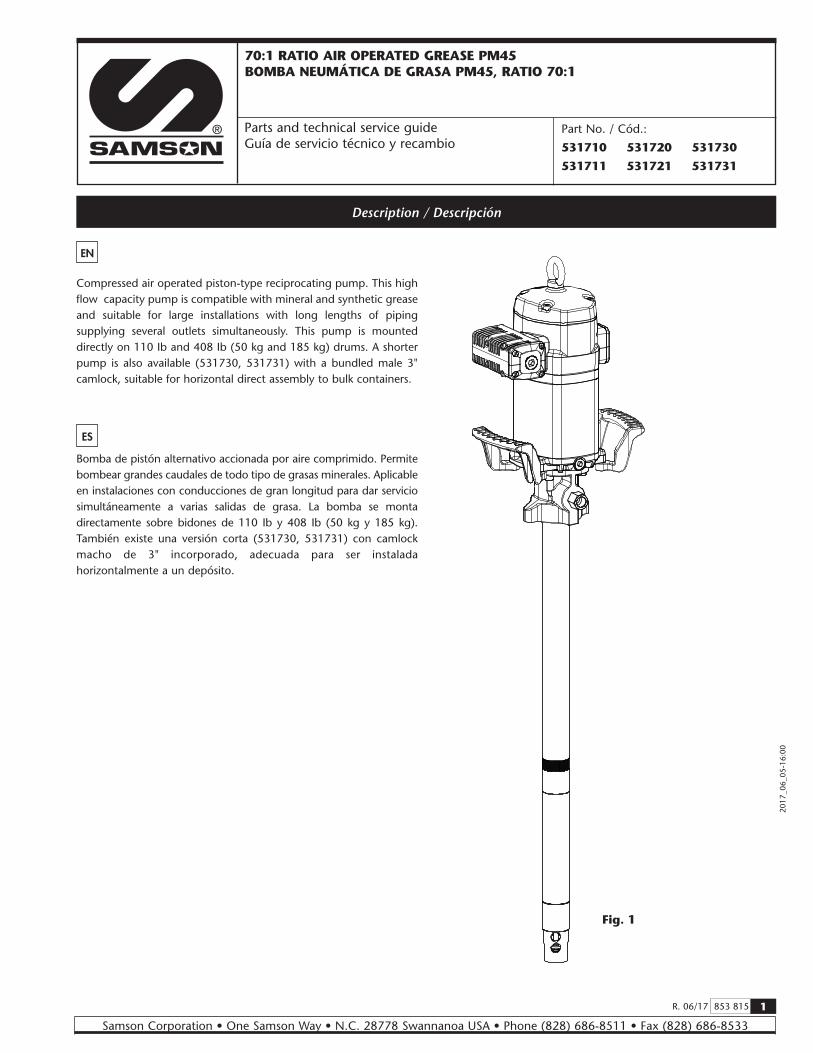
Compressed air operated piston-type reciprocating pump. This high flow capacity pump is compatible with mineral and synthetic grease and suitable for large installations with long lengths of piping supplying several outlets simultaneously. This pump is mounted directly on 110 Ib and 408 Ib (50 kg and 185 kg) drums. A shorter pump is also available (531730, 531731) with a bundled male 3" camlock, suitable for horizontal direct assembly to bulk containers.
Bomba de pistón alternativo accionada por aire comprimido. Permite bombear grandes caudales de todo tipo de grasas minerales. Aplicable en instalaciones con conducciones de gran longitud para dar servicio simultáneamente a varias salidas de grasa. La bomba se monta directamente sobre bidones de 110 Ib y 408 Ib (50 kg y 185 kg). También existe una versión corta (531730, 531731) con camlock macho de 3" incorporado, adecuada para ser instalada horizontalmente a un depósito.
EN
Part No. / Cód.:
531710 531720 531730
531711 531721 531731
ES
Fig. 1

2 853 815 R. 06/17
Samson Corporation • One Samson Way • N.C. 28778 Swannanoa USA • Phone (828) 686-8511 • Fax (828) 686-8533
2017
_06_
05-1
6:00
ES
Lea atentamente eL manuaL de instrucciones y sus advertencias antes de empezar a operar con eL equipo.
este equipo es únicamente para uso profesionaL.
¡ADVERTENCIA!
Los fluidos no adecuados para la bomba pueden causar daños a la unidad de la bomba e implicar riesgos graves daños personales. Este equipo no está destinado para el uso de fluidos que se encuentran en el apartado 1 de la Directiva de Equipos a Presión. Estos son fluidos explosivos, extremadamente inflamables, altamente inflamables, inflamables, muy tóxicos, tóxicos u oxidantes. O aquellos fluidos cuya presión de vapor sea superior a 7 psi (0.5 bar) sobre la presión atmosférica a la máxima temperatura permitida.
La bomba puede producir presiones elevadas o muy elevadas. Las altas presiones pueden ocasionar lesiones muy graves en el cuerpo humano. No exceder la presión máxima permitida de alimentación de aire de 100 psi (7 bar).
Este equipo puede contener presión almacenada, elimine la presión y desconecte la bomba del sistema de entrada y salida de fluidos en caso de realizar cualquier mantenimiento. Para asegurar el correcto funcionamiento de esta unidad, cualquier operación de mantenimiento solo será llevada a cabo por personal cualificado.
Para prevenir accidentes, cuando el equipo no esté en uso asegúrese la desconexión de este de la línea de alimentación de aire.
No altere la integridad del equipo. Use componentes originales de SAMSON Cualquier modificación no autorizada del equipo, uso indebido, mantenimiento incorrecto o la retirada de las etiquetas identificativas puede ser causa de anulación de la garantía.
Todos los accesorios que se encuentren en la línea de salida de fluido deben de ser aptos para la máxima presión generada por la bomba. Si el sistema no está diseñado para soportar la máxima presión ejercida por la bomba, instale válvulas de seguridad o válvulas de derivación.
Description / Descripción
read aLL instruction manuaLs, tags, and LabeLs before operating the equipment. this equipment is for professionaL use onLy.
WARNING!
The use of non compatible fluids may cause damage in the pump and serious personal injury. This equipment is not intended for use with fluids that fall within the Group 1 fluid as defined that are explosive, extremely flammable, highly flammable, flammable, very toxic, toxic, oxidizing or where the vapor pressure if greater than 7 psi (0.5 bar) above the pressure atmospheric at the maximum allowable temperature. The pump generates high or very high pressures. Do not exceed the maximum air inlet pressure of 100 psi (7 bar).
A direct hit against the human body may result in an injury.
This unit may have stored pressure, release all pressure and disconnect from any fluid systems before servicing. To ensure safe operation of this unit, all service work should be by qualified personnel only.
When not in use, be sure to shut off the air supply to avoid accidents.
Do not alter or modify this equipment. Use only SAMSON genuine components. Any unauthorized tampering with this equipment, improper use, poor maintenance or removal of identification labels may invalidate the guarantee.
All fittings in the system connected to the outlet of the pump should be suitable for the maximum possible pressure generated by the pump/air motor. If the systems cannot be designed to take the maximum pressure produced by the pump, safety valves or diverter valves should be fitted.
EN

3R. 06/17 853 815
Samson Corporation • One Samson Way • N.C. 28778 Swannanoa USA • Phone (828) 686-8511 • Fax (828) 686-8533
2017
_06_
05-1
6:00
Installation / Instalación
Fig. 2
Fig. 3
418006
It is recommended to install this pump on a drum using a reinforced cover due to weight considerations, but it is possible to install it two different ways:
a. Mounting with reinforced cover 418026 for 408 psi (185 kg) drum and 418025 for 110 Ib (50 kg) drum. Insert the pump through the cover and fasten it with the enclosed screws.
Insert the pump through the bung opening and fasten the cover onto the drum firmly (see figure 2).
b. Mounting with cover 418006 for 408 psi (185 kg) drum and 418016 for 110 Ib (50 kg) drum and bung adaptor 360001. Fasten the cover onto the drum and screw the nut of the bung adaptor securely into the 2" bung opening of the cover. Insert the pump through the nut and adjust it with the star nut to the desired height (see figure 3).
c. Horizontal mounting to a bulk container (531730, 531731 pumps).These pumps have the male part of a 3" camlock which would connect to the female part installed in the container (fig. 4).
EN
ES
Se recomienda la instalación sobre bidón con tapa reforzada debido a su peso y a las vibraciones generadas durante su funcionamiento, de todas formas se puede instalar la bomba de dos formas diferentes:
a. Montaje con tapa reforzada 418026 para bidón de 408 psi (185 kg) y 418025 para bidón de 110 Ib (50 kg). Inserte la bomba por la tapa y fíjela con los tornillos suministrados. Fije la tapa sobre el bidón firmemente (ver figura 2).
b. Montaje con tapa (418006 para bidón de 407.85 psi (185 kg) y 418016 para bidón de 110 Ib (50 kg) y adaptador ajustable 360001. Fije la tapa sobre el bidón y rosque la tuerca del adaptador ajustable en la rosca de la tapa. Inserte la bomba por la tuerca y fíjela con la estrella a la altura deseada (ver figura 3).
c. Montaje horizontal directamente a depósito (bombas 531730, 531731). Estas bombas incorporan la parte macho de un camlock de 3", que se acoplaría a la parte hembra colocada en el depósito (fig. 4).
Fig. 4
FEMALE 3" CAMLOCK
MALE 3" CAMLOCK

4 853 815 R. 06/17
Samson Corporation • One Samson Way • N.C. 28778 Swannanoa USA • Phone (828) 686-8511 • Fax (828) 686-8533
2017
_06_
05-1
6:00
K
Typical installation / Conexión tipo de la bomba
EN
Figure 4 is a typical installation shown with all the recommended accessories for the pump to operate correctly.
NOTE: The compressed air supply must be set between 29 and 100 psi (2 and 7 bar), being 90 psi (6 bar) the recommended pressure. An air closing valve must be installed, in order to be able to close the compressed air line at the end of the day (If the air inlet not is closed and there is a leakage in some point of the grease outlet circuit, the pump will start automatically, emptying the container).A título informativo, se muestra en la figura 4 una instalación típica
con todos los elementos recomendados para su correctofuncionamiento.
NOTA: La presión de alimentación de aire debe estar comprendida entre 29 y 100 psi (2 y 7 bar) siendo 90 psi (6 bar) la presión recomendada. Es aconsejable instalar, asimismo, una válvula de cierre para poder cerrar la alimentación de aire al final de la jornada (en caso de roturas o fugas en la salida de grasa, si la alimentación de aire no está cerrada, la bomba se pondría en marcha automáticamente, pudiendo vaciarse completamente el depósito).
ES
Fig. 5
Pos Description Descripción Part No. / Cod.A Air shut off valve Válvula de corte de aire 950319+239004B Filter regulator Filtro regulador 241001C Air hose Manguera de aire 362100D Quick coupling Enchufe rápido 251412E Connection nipple Conector rápido 255412F Pump, 408 lb (185 kg) drum Bomba, bidón 408 lb (185 kg) 531410G Grease hose Manguera grasa 412392H Grease shut off valve Válvula de cierre de grasa 950304I Cover Tapa 418026J Follower plate Plato seguidor 417004K Pressure Relief Valve Válvula de descarga
39.37 in
59.06 in

5R. 06/17 853 815
Samson Corporation • One Samson Way • N.C. 28778 Swannanoa USA • Phone (828) 686-8511 • Fax (828) 686-8533
2017
_06_
05-1
6:00
Operation / Modo de empleo
EN
This pump is self–priming. To prime it the first time, it is convenient to connect the air supply to the pump while keeping the outlet gun opened, and increase the air pressure slowly from 0 psi (0 bar) to the desired pressure by using a pressure regulator. Once grease starts flowing through all the outlets, the pump is primed.The pump starts to pump when an outlet valve is opened, for example a grease control gun.NOTE: It is important that the foot valve do not come in contact with dirty areas, such as a workshop floor, because it may become contaminated with dirt or other particles that can damage the seals.
Esta bomba es auto-cebante. Para cebarla la primera vez, conectar el aire a la bomba manteniendo abierta la pistola de salida, incrementando la presión lentamente desde 0 psi (0 bar) a la presión deseada con el regulador de presión. La bomba está cebada cuando la grasa sale por todas las salidas.La bomba empieza a bombear cuando se abre la válvula de salida, por ejemplo una pistola de control de grasa.NOTA: Es importante que la válvula de pie no esté en contacto con zonas sucias, tales como el suelo de un taller, porque puede entrar virutas o partículas que podrían llegar a dañar el mecanismo de la bomba.
ES
Troubleshooting / Anomalías y sus soluciones
EN
Symptoms Possible Reasons Solutions
The pump is not working or there is no grease delivery.
No suitable air supply pressure. Increase the air supply pressure.Some outlet circuit element is clogged or closed. Clean or open the outlet circuit.There is an air pocket in the grease inlet area. Stir and repack the grease.
The pump begins to operate very fast.
The drum is empty or the grease level is beneath the suction tube inlet.
Replace the drum or insert the suction tube until the inlet reaches the grease level.
The pump keeps on operating although the grease outlet is closed.
There is a grease leakage at some point in the circuit. Verify and tighten or repair.Contamination in the upper valve. Disassemble and clean. Replace if damaged.
Contamination in the foot valve. Disassemble and clean. Replace if damaged.
Grease leakage through the air outlet muffler or the leakage warning hole on the pump body (69).
Grease has passed over to the air motor caused by scratched piston rod (49) or worn or damaged seals (54, 57).
Verify the piston rod (49) and replace damaged / worn parts.
Air leakage through the air outlet muffler (25).
Damaged or worn piston O ring (44). Replace O Ring (44).The air seal (8) of the inverter assembly is damaged or worn. Replace the air seal (8).
Damaged or worn spool seals. Replace the seals (18) and (20).
Grease output too low or diminishes over time.
Contamination in the foot valve. Remove and clean. Replace if damaged.Contamination in the upper valve. Remove and clean. Replace if damaged.The exhaust muffler is clogged by compressed air dirt or lubricant. Replace the muffler felt.
ES
Síntomas Posibles causas Soluciones
La bomba no funciona o no hay entrega de grasa.
Presión de suministro de aire no adecuada. Incremente la presión del aire de suministro.Algún elemento del circuito de salida está obstruido o cerrado.
Limpie o abra el circuito de salida.
Se ha creado bolsas de aire alrededor de la zona de succión de la bomba.
Compacte la grasa.
La bomba empieza a funcionar mucho más aprisa.
El depósito esta vacío o el nivel esta por debajo del tubo de succión.
Llene el depósito o cale el tubo de succión hasta llegar al nivel de la grasa.
La bomba sigue funcionando aunque se cierre la salida de grasa.
Existe fuga de grasa en algún punto del circuito. Verifique y apriete o repare.Válvula de impulsión no cierra por impurezas. Desmonte y limpie.Válvula inferior no cierra por impurezas o por deterioro. Desmonte y limpie. Sustituya en caso de deterioro.
Pérdida de grasa por los silenciadores de escape de aire o por el orificio testigo de fugas en el cuerpo de salida (69).
La grasa ha pasado al motor de aire causado por vástago (49) rayado o desgaste o deterioro de las juntas (54, 57) del inserto.
Verifique el vástago (49) y sustituya las piezas gastadas/ dañadas.
Pérdida de aire por el escape de aire (25).
Junta del émbolo de aire desgastada (44). Sustituya la junta (44).Junta del pistón sensor desgastada (8). Sustituya la junta (8).Juntas de la corredera inversora desgastadas. Sustituya las juntas (18) y (20).
Disminución del caudal entregado.
Válvula inferior con impurezas. Desmonte y limpie. Sustituya en caso de deterioro.Válvula superior con impurezas. Desmonte y limpie. Sustituya en caso de deterioro.El silenciador está colmatado por impurezas o lubricante del aire comprimido. Reemplace el fieltro del silenciador.

6 853 815 R. 06/17
Samson Corporation • One Samson Way • N.C. 28778 Swannanoa USA • Phone (828) 686-8511 • Fax (828) 686-8533
2017
_06_
05-1
6:00
1. Fije la bomba en posición horizontal en una mordaza (fig. 5). Dé unos golpes con un martillo en el tubo superior (73), cerca de la unión con el cuerpo (69) para romper el sellador de rosca.
2. Desenrosque la tuerca de cebador (94) y desmonte éste (93).3. Coloque una barra o tubo robusto y largo (para servir de palanca)
en la salida de material, y úselo para desenroscar el motor.4. Una vez desenroscado, tire del motor hasta ver el pasador (70)
del vástago (49). Con un martillo y un botador, sacar el pasador (70). El motor queda suelto.
Repair and cleaning procedure / Procedimientos de reparación y limpieza
EN
WARNING: Before starting any kind of maintenance or repair, disconnect the compressed air supply and open the valve to relieve the grease pressure.
ATENCIÓN: Antes de empezar cualquier tipo de mantenimiento o reparación, desconecte el aire de alimentación y accione la válvula de salida para soltar la presión de la grasa.
ES
Separate the air motor from the pump / Como separar el motor de aire de la bomba
1. Fix the pump in a vise in horizontal position (fig. 5). Gently blow with a hammer the upper tube (73) close to the body (69) in order to break the thread locker.
2. Unscrew the nut (94) and remove the primer (93).3. Put a bar, rod or any kind of strong tube in the fluid outlet and
use it as a lever to unscrew the air motor.4. Once unscrewed, pull the motor away untill the elastic pin (70)
into the rod (49) becomes visible. With a hammer and a suitable pin punch, eject the pin (70). The motor becomes loose.
EN ES
Fig. 669497073
9394

7R. 06/17 853 815
Samson Corporation • One Samson Way • N.C. 28778 Swannanoa USA • Phone (828) 686-8511 • Fax (828) 686-8533
2017
_06_
05-1
6:00
Repair and cleaning procedure / Procedimientos de reparación y limpieza
Clean the muffler / Limpieza del silenciador
1. Unscrew bolts (27). 2. Remove exhaust assembly (25). 3. Unscrew the bolts (24) and remove the cap (29). 4. Remove the felt (30). 5. Remove the felt (31) and deflector (28). 6. Remove the bottom felt (30) and replace it with a new one. 7. Put back the deflector (28). 8. Insert the screws (27) and then a new felt (31). If not in this
order, it could be tricky to insert the screws. 9. Put a new felt (30). 10. Put back the cap (29) and its screws (24). 11. Ensuring the screws (27) stay into the muffler (25), put said
muffler on the motor and fix it with said screws. 12. It is also available a whole muffler assembly kit (539005), with
replaces the old one just operating the screws (27).
EN
1. Desenrosque los tornillos (27). 2. Retire el conjunto del silencioso (25). 3. Desenrosque los 4 tornillos (24) y retire la tapa (29). 4. Extraiga el fieltro (30). 5. Extraiga el fieltro (31) y el deflector (28). 6. Extraiga el fieltro del fondo (30) y sustitúyalo por uno nuevo. 7. Coloque de nuevo el deflector (28). 8. Inserte los tornillos (27) y posteriormente un nuevo fieltro (31).
Si no se hace en este orden, puede ser complicado insertar los tornillos.
9. Coloque un nuevo fieltro (30). 10. Coloque la tapa (29) y sus tornillos (24). 11. Asegurándose de que los tornillos (27) no se salen del
silenciador (25), sitúe dicho silenciador en el motor y rosque dichos tornillos.
12. También está disponible un kit de silenciador completo (539005), con el cual sólo sería necesario sustituir el silenciador viejo por el nuevo mediante los tornillos (27).
ES
25
17
30
24
29
27
28
30
31
Fig. 7

8 853 815 R. 06/17
Samson Corporation • One Samson Way • N.C. 28778 Swannanoa USA • Phone (828) 686-8511 • Fax (828) 686-8533
2017
_06_
05-1
6:00
Repair and cleaning procedure / Procedimentos de reparación y limpieza
Air motor seals / Juntas del motor de aire
EN ES
1. Unscrew the bolts (2) and remove the cap (3).2. Unscrew the sensor sleeve (4).3. With a manual clamp on the nut (5), pull the rod (40) outwards
until its central recess appears (fig. 9a). Then, with another manual clamp, grab the rod (40) on said recess to prevent sealing surface to be damaged, and unscrew the nut (5) (fig. 9b).
4. Remove o-ring (6) and ring (7), and replace them with new ones later.5. Unscrew the bolts (55). Pull the motor body (13) outwards to
free it along with bridle (36).6. Take away the gasket (9) and replace its seals (8) and (10).7. Unscrew the bolts (37) and split the motor (13) from the bridle
(36). Take away the washer (32) and replace the seal (8).8. Take away the cylinder (50) while carefully holding the air piston
(45). Replace the piston seal (44).9. Reassemble in reverse order, applying thread locker in screws
(37), nut (5) and sensor sleeve (4).NOTA: las juntas nuevas necesarias están incluidas en el kit 539002.
1. Desenrosque los cuatro tornillos (2) y quite la tapa (3).2. Desenrosque el tapón inversor (4).3. Con ayuda de una mordaza manual sobre el casquillo (5), tire
hacia fuera del vástago (40) hasta que aparezca su rebaje central (fig. 9a). Después, con otra mordaza manual agarre el vástago (40) en dicha zona rebajada central para no dañar la superficie destinada al sellado y desenrosque el casquillo (5) (fig. 9b).
4. Deseche la tórica (6) y el aro (7), y use otros nuevos posteriormente al volver a montar.
5. Desenrosque los cuatro tornillos (55). Tire hacia arriba del cabezal motor (13) hasta liberarlo junto con la brida (36).
6. Quite el casquillo inversor (9). Sustituya las juntas (8) y (10) de este casquillo.
7. Desenrosque los cinco tornillos (37) y separe el cuerpo motor (13) de la brida (36). Extraiga la arandela (32) y sustituya la junta (8).
8. Retire el cilindro (50) sujetando con cuidado el émbolo (45). Sustituya la junta (44) de dicho émbolo.
9. Vuelva a montar el conjunto en sentido inverso, aplicando fijador de rosca en los tornillos (37), casquillo (5) y tapón inversor (4).
NOTA: las juntas nuevas necesarias están incluidas en el kit 539002.
1. Unscrew the bolts (24) and remove the cap (23).2. Ensuring the screws (27) remain into the muffler (25), unscrew
them and take away the muffler. Take away the o-ring (16).3. Strike gently with a plastic tool through exhaust seat to remove
the spool valve (19).4. Replace the seals (18) and (20) with new ones or replace the
whole spool (19) with its seals factory installed (kit 539006). This is strongly recommended in order to ensure the correct assembly of the seals.
EN ES
1. Desenrosque los tornillos (24) y retire la tapa del tope de corredera (23).
2. Desenrosque los tornillos (27) y, asegurándose de que no se salen del silenciador (25), separe dicho silenciador del motor. Extraiga la tórica (16).
3. Con ayuda de un útil de plástico, golpeando suavemente por el lado del silenciador, extraiga la corredera del distribuidor (19).
4. Sustituya las juntas de corredera (18) y (20), o bien sustituya la corredera (19) completa con sus juntas ya instaladas de fábrica (kit 539006). Ésta es la opción recomendada para asegurar que las juntas están correctamente instaladas.
Air distributor / Distribuidor de aire
Fig. 8
27
25
16
2319
2418
20

9R. 06/17 853 815
Samson Corporation • One Samson Way • N.C. 28778 Swannanoa USA • Phone (828) 686-8511 • Fax (828) 686-8533
2017
_06_
05-1
6:00
Repair and cleaning procedure / Procedimentos de reparación y limpieza
Air motor seals / Juntas del motor de aire
2
3
4
5
7
6
8
910
13
8
32
36
37
50
44
45
55Fig. 9
40
Fig. 9a
Fig. 9b

10 853 815 R. 06/17
Samson Corporation • One Samson Way • N.C. 28778 Swannanoa USA • Phone (828) 686-8511 • Fax (828) 686-8533
2017
_06_
05-1
6:00
Repair and cleaning procedure / Procedimentos de reparación y limpieza
Lower seals kit / Sustitución juntas bajos
51
52
5354555456
57
71
68
69
75
80
85
72
73
74
81
828382
74
84
8687888991
9074
92
74
85
IMPO
RTA
NT:
SEA
LS O
RIEN
TATI
ON
AS
SHO
WN
IMPO
RTA
NT:
SEA
L O
RIEN
TATI
ON
AS
SHO
WN

11R. 06/17 853 815
Samson Corporation • One Samson Way • N.C. 28778 Swannanoa USA • Phone (828) 686-8511 • Fax (828) 686-8533
2017
_06_
05-1
6:00
Repair and cleaning procedure / Procedimentos de reparación y limpieza
EN
1. Separe el motor de aire de los bajos, tal como se describe anteriormente.
2. Desenrosque los tornillos (68) y extraiga el cuerpo (69).3. Desenrosque el inserto (51) y extraiga la arandela (53) y el
portajuntas (56). Reemplace por juntas nuevas las (52), (54) x2, (55) y (57).
4. Extraiga el conjunto formado por (71), (75), (80) y (85) del interior de los bajos.
5. Con el tubo (73) amarrado en mordaza, desenrosque el tubo (95).6. Extraiga los componentes (74) x 2, (91), (92). Retire el circlip (87)
de la válvula (91) y reemplace los componentes (88), (89) y (90) por unos nuevos.
7. Aprovechando el moleteado, desenrosque el componente (81) y reemplace las juntas (82) x 2 y (83) por unas nuevas.
8. Vuelva a ensamblar todo en orden inverso, sustituyendo todas las juntas metálicas (72) y (74).
9. Todas las juntas necesarias se incluyen en el kit 534700.
ES
Lower seals kit / Sustitución juntas bajos
1. Take away the air motor from the lowers, as described previously.2. Unscrew the bolts (68) and remove the body (69).3. Unscrew the scraper nut (51) and extract both the washer (53)
and the gasket (56). Replace seals (52), (54) x2, (55) and (57) by new ones.
4. Take away the assembly consisting of parts (71), (75), (80) and (85) from the lowers.
5. With the tube (73) secured on a vise, unscrew the tube (95).6. Extract the parts 2 x (74), (91) and (92). Take away the circlip
(87) from the valve (91) and replace parts (88), (89) and (90) by new ones.
7. Using the knurled surface, unscrew the part (81) and replace the seals 2 x (82) and (83) by new ones.
8. Assemble again in reverse order, replacing all metallic seals (72) and (74) by new ones.
9. All necessary seals are inlcuded in the available kit 534700.
Cleaning or replacing the lowers valves / Limpieza o sustitución de válvulas de bajos
1. Disassembling the lowers as described previously, the fluid valves can be easily accessed.
2. Lower valve: parts from (86) to (92). Kit 534701.3. Upper valve: parts from (76) to (80). Kit 534402.
NOTE: to unscrew the upper valve (80), secure it in a vise and unscrew the rod (75) by grabbing it in the pin (70) area in order to avoid damaging the quality of the surface intended for sealing.
EN ES
1. Desmontando los bajos según lo descrito en el apartado anterior se puede acceder fácilmente a las válvulas de los bajos.
2. Válvula inferior: componentes del (86) al (92). Kit 534701.3. Válvula superior: componentes del (76) al (80). Kit 534402.
NOTA: para desenroscar la válvula superior (80), fíjela en una mordaza y desenrosque el pistón de alta presión (75) agarrando por la zona del pasador (70) para no dañar la calidad superficial destinada al sellado.
Spare parts / Recambios
EN ES
Repair kit / Kit de reparación
Part. No. / Cód. Description Descripción Ind. pos.534700 Lower seals kit Kit juntas bajos 52, 2 x 54, 55, 57, 72, 4 x 74, 2 x 82, 83, 88, 89, 90534701 Lower valve kit Kit válvula inferior 86, 87, 88, 89, 90, 91, 92534402 Upper valve kit Kit válvula superior 76, 77, 78, 79, 80539002 Air motor seals kit Kit juntas motor aire 6, 7, 2 x 8, 10, 44539005 Exhaust muffler kit Kit silenciador 16, 17, 4 x 24, 25, 4 x 26, 4 x 27, 28, 29, 2 x 30, 31539006 Spool + seals kit Kit corredera + juntas 5 x 18, 19, 20
12 853 815 R. 06/17
Samson Corporation • One Samson Way • N.C. 28778 Swannanoa USA • Phone (828) 686-8511 • Fax (828) 686-8533
2017
_06_
05-1
6:00
Spare parts / Recambios
EN ES
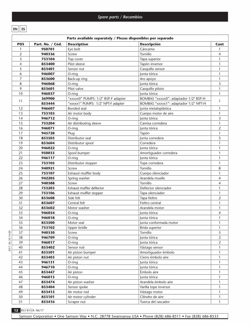
Parts available separately / Piezas disponibles por separado
POS Part. No. / Cód. Description Descripción Cant1 950701 Eye bolt Cáncamo 12 940336 Screw Tornillo 43 753104 Top cover Tapa superior 14 853400 Pilot sleeve Tapón inversor 15 853401 Sensor nut Casquillo sensor 16 946007 O-ring Junta tórica 17 853600 Back-up ring Aro apoyo 18 946068 O-ring Junta tórica 39 853601 Pilot valve Casquillo piloto 110 946037 O-ring Junta tórica 1
11369900 “xxxxx0” PUMPS: 1/2" BSP-F adapter BOMBAS “xxxxx0”: adaptador 1/2" BSP-H
1853444 “xxxxx1” PUMPS: 1/2" NPT-F adapter BOMBAS “xxxxx1”: adaptador 1/2" NPT-H
12 946607 Bonded seal Junta metaloplástica 113 753103 Air motor body Cuerpo motor de aire 114 946712 O-ring Junta tórica 315 753204 Air distributing sleeve Camisa corredera 116 946071 O-ring Junta tórica 217 945728 Plug Tapón 118 853503 Distributor seal Junta corredera 519 853604 Distributor spool Corredera 120 946022 O-ring Junta tórica 121 950033 Spool bumper Amortiguador corredera 122 946117 O-ring Junta tórica 123 753105 Distributor stopper Tope corredera 124 940921 Screw Tornillo 825 753107 Exhaust muffler body Cuerpo silenciador 126 942205 Spring washer Arandela muelle 427 940388 Screw Tornillo 428 753203 Exhaust muffler deflector Deflector silenciador 129 753106 Exhaust muffler stopper Tapa silenciador 130 853608 Side felt Tapa fieltro 231 853607 Central felt Fieltro central 132 853602 Motor washer Arandela motor 133 946054 O-ring Junta tórica 434 946018 O-ring Junta tórica 135 853500 Motor seal Junta conformada motor 136 753102 Upper bridle Brida superior 137 940330 Screw Tornillo 538 946709 O-ring Junta tórica 239 946017 O-ring Junta tórica 240 853402 Sensor rod Vástago sensor 141 853501 Air piston bumper Amortiguador émbolo 142 853403 Air piston nut Cierre émbolo aire 143 946131 O-ring Junta tórica 144 946710 O-ring Junta tórica 145 853447 Air piston Émbolo aire 146 946015 O-ring Junta tórica 147 853474 Air piston washer Arandela émbolo aire 148 853404 Sensor spoke Varilla tope inversor 149 853415 Air motor rod Vástago motor 150 853101 Air motor cylinder Cilindro de aire 151 853416 Scraper nut Tuerca del rascador 1

13R. 06/17 853 815
Samson Corporation • One Samson Way • N.C. 28778 Swannanoa USA • Phone (828) 686-8511 • Fax (828) 686-8533
2017
_06_
05-1
6:00
52 946572 Scraper Rascador 153 853418 Scraper washer Arandela del rascador 154 946101 HP seal Junta alta presión 255 946208 Slide ring Aro guía 156 853419 Hp seals gasket Portajuntas alta presión 157 946081 O-ring Junta tórica 158 753100 Lower bridle Brida inferior 159 853606 Handle Asa 260 940321 Screw Tornillo 461 942008 Washer Arandela 462 942208 Spring washer Arandela muelle 463 940337 Screw Tornillo 464 946197 O-ring Junta tórica 165 940370 Screw Tornillo 166 945100 Plug Tapón 167 946601 Bonded seal Junta metaloplástica 168 940340 Screw Tornillo 469 753002 Pump body Cuerpo salida 170 943041 Elastic pin Pasador elástico 3
71
853420 xxxx1x pumps: long connecting rod Bombas xxxx1x: varilla de conexión larga
1853440 xxxx2x pumps: short connecting rod Bombas xxxx2x: varilla de conexión corta
853433 xxxx3x pumps: bulk connecting rodBombas xxxx3x: varilla de conexión p/ granel
72 942036 Metallic seal Junta metálica 1
73853428 xxxx1x pumps: long upper tube Bombas xxxx1x: tubo superior largo
1853441 xxxx2x pumps: short upper tube Bombas xxxx2x: tubo superior corto853438 xxxx3x pumps: bulk upper tube Bombas xxxx3x: tubo superior p/ granel
74 942033 Metallic seal Junta metálica 475 853434 HP piston Pistón alta presión 176 943806 key Chaveta 177 944010 Ball Bola 178 853422 Spacer Espaciador 179 942013 Metallic seal Junta metálica 180 853432 Upper valve body Cuerpo válvula superior 181 853439 Barrel Camisa pistón 182 946210 Slide ring Aro guía 283 946801 HP seal Junta alta presión 184 853430 Central tube Tubo intermedio 185 853435 Primer rod Varilla cebador 186 853436 Valve stop Tope válvula 187 942720 V-clip Circlip tipo V 188 853613 Valve washer Arandela válvula 189 946211 Slide ring Aro guía 190 946105 HP seal Junta alta presión 191 853437 Lower valve body Cuerpo válvula inferior 192 853426 Lower valve base Base válvula inferior 193 853427 Shovel Cebador 194 941106 Nut Tuerca 195 853431 Lower tube Tubo inferior 196 853443 “xxxxx0” PUMPS: 1/2" BSP-F adapter BOMBAS “xxxxx0”: adaptador 1/2" BSP-H 197 946085 O-ring Junta tórica 198 753110 3" camlock male adaptor Adaptador camlock 3" macho 199 942210 Spring washer Arandela muelle 4100 940340 Screw Tornillo 4
EN ES
Spare parts / Recambios

14 853 815 R. 06/17
Samson Corporation • One Samson Way • N.C. 28778 Swannanoa USA • Phone (828) 686-8511 • Fax (828) 686-8533
2017
_06_
05-1
6:00
Parts drawing / Dibujo de piezas
1
2
3
456789
108
1112
13
141516
17
18192021222324
25
2627
28
2924
323383435
36
3738
39
40
41
42
43
44
45
46
47
48
49
50
38
39
51
52
53
545554
59
60616263
56
5758
64
656667
68
69
70
71
72
73
7470
75
7677
7879
80
81
74
8283
82
84
70
85
868788899091
74
92
749394
95
456789
108
303130
96
97
9899100

15R. 06/17 853 815
Samson Corporation • One Samson Way • N.C. 28778 Swannanoa USA • Phone (828) 686-8511 • Fax (828) 686-8533
2017
_06_
05-1
6:00
Dimensions / Dimensiones
Technical data / Datos técnicos
EN ES
531710 / 531720 / 531730 531711 / 531721 / 531731
Maximum air pressure Presión de aire máxima 100 psi (7 bar)Minimum air pressure Presión de aire mínima 29 psi (2 bar)Maximum delivery Caudal máximo 16 lb/min @ 100 psi (7.5 kg/min @ 7 bar)Air inlet thread Rosca entrada aire 1/2" BSP 1/2" NPTFluid outlet thread Rosca salida fluido 1/2" BSP 1/2" NPTAir piston diameter Diámetro pistón de aire 4.5" (115 mm)Stroke Carrera 4" (100 mm)Weight Peso 55 lb (25 kg)
MODELA
in (mm)B
in (mm)F
in (mm)WEIGHT
531710/531711 33” (855) 53” (1357) N.A. 55 lb (25 kg)531720/531721 25” (650) 45” (1152) N.A. 50 lb (23 kg)531730/531731 19” (490) 39” (992) 16-14 (410) 46 Ib (21 kg)
0 38 76 114 152 190 228 266 304500
450
400
350
300
250
200
150
100
50
0
2500
2000
1500
1000
500
0
Cycles/min. Ciclos/min.bar psi
Out
let
pre
ssur
ePr
esió
n sa
lida
Flow / Caudal
Air
cons
ump
tion
Con
sum
o de
aire
kg/min
lb/min
Nl/min scfm
MODEL C, D E
531710/ 531720/ 531730 1/2" BSP-F1/4" BSP-F
531711/ 531721/531731 1/2" NPT-F
0 1 2 3 4 5 6 7 8
0 2,2 4,4 6,6 8,8 11 13,2 15,4 17,6
88
70
53
35
17
0
C
E D
A
Ø 50
B
F
4xM10 holes/agujerosØ112 mm hole pattern/patrón de agujeros
7251
6526
5801
5076
4351
3626
2900
2175
1450
725
0
100 psi (7 bar)72 psi (5 bar)43 psi (3 bar) Consumo @ 100 psiConsumo @ 72 psiConsumo @ 43 psi
17.56
" (44
6 mm)

16 853 815 R. 06/17
Samson Corporation • One Samson Way • N.C. 28778 Swannanoa USA • Phone (828) 686-8511 • Fax (828) 686-8533
2017
_06_
05-1
6:00
www.samsoncorporation.com
Distributed by