63-2557 tyco 2 and 3-way butterfly assemblies · · 2014-09-252 and 3-way butterfly assemblies...
TRANSCRIPT
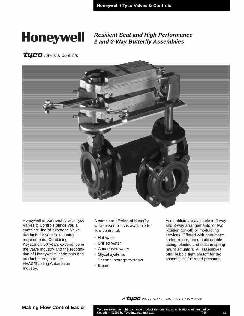
Resilient Seat and High Performance2 and 3-Way Butterfly Assemblies
Tyco reserves the right to change product designs and specifications without notice.Copyright ©1999 by Tyco International Ltd. 7/99 p1
Honeywell / Tyco Valves & Controls
Making Flow Control Easier
Honeywell in partnership with TycoValves & Controls brings you acomplete line of Keystone Valveproducts for your flow controlrequirements. CombiningKeystone’s 50 years experience inthe valve industry and the recogni-tion of Honeywell’s leadership andproduct strength in theHVAC/Building AutomationIndustry.
A complete offering of butterflyvalve assemblies is available forflow control of:
• Hot water• Chilled water• Condensed water• Glycol systems• Thermal storage systems• Steam
Assemblies are available in 2-wayand 3-way arrangements for twoposition (on-off) or modulatingservices. Offered with pneumaticspring return, pneumatic doubleacting, electric and electric springreturn actuators. All assembliesoffer bubble tight shutoff for theassemblies’ full rated pressure.

Tyco reserves the right to change product designs and specifications without notice.Copyright ©1999 by Tyco International Ltd. 7/99 p2
Features and Benefits• Molded-in resilient seat provides
bubble-tight shutoff to 250 psi (Fig.222) 150 psi (Fig. AR2).
• Offered in two body styles: wafer andlug. The lugged body is drilled andtapped for isolation and removal ofdownstream piping at full ratedpressure (Fig. AR2 – 75 psi).
• Round, polished disc and hub edgeprovides 360 degree concentricseating, minimum flow restriction,lower torques and longer seat life.
• Upper and lower inboard bronzebearings ensure longer service lifewith low operating torques.
• Thru-stem design provides highstrength and positive disc control withstandardized end connection foroperator interchangeability.
• Extended neck allows adequateclearance for flanges and insulation.
• Bi-directional, self-adjusting stemseal, located in the upper journal, issuitable for vacuum and pressurewhile also preventing externalcontamination of the stem area.
• Heavy-duty corrosion resistant topbushing, located in the upper journal,absorbs actuator side thrust.
• Cast-in top plate is an integral part ofthe body and is standardized to allowdirect mounting of all Keystoneactuators.
• Each valve is factory tested to 110percent of specified pressure rating.
Keystone Figure 222 and Figure AR2 Resilient Seat Butterfly Valves
Materials - Figure 222Part Material Material Standards
1 Body Cast iron ASTM-A 126 Class B
2 Disc Aluminum bronze * ASTM-A 148 UNS C95200 Grade A*316 Stainless steel ASTM-A 743 CF8M
3 Stem 416 Stainless steel ASTM-A 582 UNS S41600
4 Molded-in liner EPDM
5 Inboard bearings Bronze
6 Upper bushing Polyester
7 Upper stem seal NBR
Materials - Figure AR2Part Material Material Standards
1 Body Cast iron* ASTM-A 126 Class B*Ductile iron ASTM-A 395 GR 60/40/18Carbon steel ASTM A 216 WCB
2 Disc Ductile iron ASTM A 536 GR 65/45/12Aluminum bronze* ASTM B 148, UNS C95200 Grade A*316 Stainless steel ASTM A 743, CF8M
3 Stem 316 Stainless steel* ASTM A 276 UNS S31600*18-8 Stainless steel (14–20-inch)* ASTM A 276 UNS S30400*17-4PH Stainless steel (24–36-inch) ASTM A 564 UNS S17400Phosphate treated steel (2–20-inch) ASTM A 108 UNS G10450
4 Seat NBR food grade (0°F–212°F)EPDM food grade (-40°F–250°F)*
5 Upper stem bushing Polyester (2–20-inch)Bronze (24–36-inch)
6 Stem packing NBR
7 Torque plug (2–12-inch) 316 Stainless steel ASTM A 276 UNS S31600 cond. ADisc screws (14–20-inch) 316 Stainless steel ASTM F 593 Group 2 cond. CW1Taper pins (24–36-inch) 17-4PH Stainless steel ASTM A 564 UNS S17400 H1075
8 Bearings (2–12-inch) Sintered metal
* Standard Materials Keystone Figure AR1 (Wafer Style pictured, AR2 Lug Style is standard)
3
6
7
1
5
2
4
5
3
56
1
8
7
2
4
Honeywell / Tyco Valves & Controls

Tyco reserves the right to change product designs and specifications without notice.Copyright ©1999 by Tyco International Ltd. 7/99 p3
Figure 222 - Figure AR2 Valve Assemblies
Note
AR2 valves are utilized for all assemblies14-inch – 20-inch (150 psi) and undercutassemblies (50 psi) size 8-inch – 20-inch.
222 valves are utilized for all assemblies2-inch—12-inch @ 200 psi and undercutassemblies 2-inch—6-inch at 100 psi.
Figure 222* - Dimensions - inches [mm] Valve A B C D Tap Lug Data Q E F G HSize Tap Size Bolt No.
Circle Bolts
2 2.06 [52] 4.13 [105] 5.31 [135] 1.69 [43] .625-11 UNC-2B 3.25 [83] 4 1.38 [35] 4 [102] 1.25 [32] .56 [14] .38 [10]
2.5 2.56 [64] 4.63 [118] 5.94 [150] 1.81 [46] .625-11 UNC-2B 3.25 [83] 4 2.00 [51] 4 [102] 1.25 [32] .56 [14] .38 [10]
3 3.06 [77] 5.19 [132] 6.31 [160] 1.81 [46] .625-11 UNC-2B 3.25 [83] 4 2.63 [67] 4 [102] 1.25 [32] .56 [14] .38 [10]
4 4.06 [103] 6.38 [162] 7.13 [181] 2.06 [52] .625-11 UNC-2B 3.25 [83] 8 3.69 [93] 4 [102] 1.25 [32] .63 [16] .44 [11]
5 5.06 [128] 7.38 [188] 7.69 [195] 2.25 [56] .750-10 UNC-2B 3.25 [83] 8 4.75 [120] 4 [102] 1.25 [32] .75 [19] .50 [13]
6 5.81 [147] 8.50 [216] 8.31 [210] 2.25 [56] .750-10 UNC-2B 3.25 [83] 8 5.56 [141] 4 [102] 1.25 [32] .75 [19] .50 [13]
8 7.81 [198] 10.69 [272] 9.50 [241] 2.38 [60] .750-10 UNC-2B 5.00 [127] 8 7.75 [196] 6 [152] 1.25 [32] .88 [22] .63 [16]
10 9.81 [249] 13.00 [330] 10.88 [275] 2.69 [68] .875-9 UNC-2B 5.00 [127] 12 9.75 [247] 6 [152] 2.00 [51] 1.13 [29] N/A
12 11.81 [300] 14.81 [376] 12.25 [311] 3.13 [78] .875-9 UNC-2B 5.00 [127] 12 11.75 [298] 6 [152] 2.00 [51] 1.13 [29] N/A
* Figure 222 valves are rated for 250 psi bi-directional service. Standard actuator sizing is based on 150 psi line pressure.
Figure AR2 - Dimensions - inches [mm] Valve A B C D Tap Lug Data Q E F G HSize Tap Size Bolt No.
Circle Bolts
4 4.00 [102] 6.38 [162] 7.00 [178] 2.00 [51] .625-11 UNC-2B 7.50 [191] 8 3.44 [87] 4 [102] 1.25 [32] .63 [16] .44 [11]
5 5.00 [127] 7.38 [187] 7.50 [191] 2.13 [54] .750-10 UNC-2B 8.50 [216] 8 4.54 [115] 4 [102] 1.25 [32] .75 [19] .50 [13]
6 5.75 [146] 8.50 [216] 8.00 [203] 2.13 [54] .750-10 UNC-2B 9.50 [241] 8 5.35 [136] 4 [102] 1.25 [32] .75 [19] .50 [13]
8 7.75 [197] 10.69 [272] 9.50 [241] 2.50 [64] .750-10 UNC-2B 11.75 [298] 8 7.36 [187] 6 [152] 1.25 [32] .88 [22] .63 [16]
10 9.75 [248] 13.00 [330] 10.75 [273] 2.50 [64] .875-9 UNC-2B 14.25 [362] 12 9.46 [240] 6 [152] 2.00 [51] 1.13 [29] N/A
12 11.75 [298] 14.81 [376] 12.25 [311] 3.00 [76] .875-9 UNC-2B 17.00 [432] 12 11.40 [290] 6 [152] 2.00 [51] 1.13 [29] N/A
14 13.25 [337] 16.88 [429] 12.00 [305] 3.00 [76] 1.000-8 NC 18.75 [476] 12 12.95 [329] 6 [152] 3.00 [76] 1.38 [35] N/A
16 15.25 [387] 19.25 [489] 12.94 [329] 4.00 [102] 1.000-8 NC 21.25 [540] 16 14.78 [375] 6 [152] 3.02 [77] 1.63 [41] N/A
18 17.25 [438] 21.50 [546] 14.50 [368] 4.25 [108] 1.125-7 NC 22.75 [578] 16 16.79 [426] 8 [203] 4.25 [108] 1.88 [48] N/A
20 19.25 [489] 23.75 [603] 15.88 [403] 5.00 [127] 1.125-7 NC 25.00 [645] 20 18.64 [473] 8 [203] 4.25 [108] 1.88 [48] N/A
222Lug
AR2Lug
KEYSTONEH
D
45˚
E
B
G
A
F
C
D
Q
EH
B
Honeywell / Tyco Valves & Controls
Tyco reserves the right to change product designs and specifications without notice.Copyright ©1999 by Tyco International Ltd. 7/99 p4
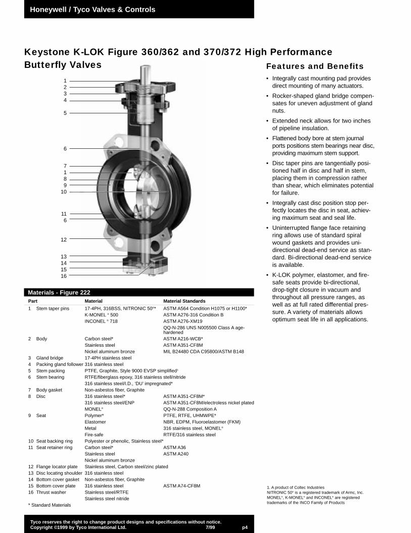
Features and Benefits• Integrally cast mounting pad provides
direct mounting of many actuators.
• Rocker-shaped gland bridge compen-sates for uneven adjustment of glandnuts.
• Extended neck allows for two inchesof pipeline insulation.
• Flattened body bore at stem journalports positions stem bearings near disc,providing maximum stem support.
• Disc taper pins are tangentially posi-tioned half in disc and half in stem,placing them in compression ratherthan shear, which eliminates potentialfor failure.
• Integrally cast disc position stop per-fectly locates the disc in seat, achiev-ing maximum seat and seal life.
• Uninterrupted flange face retainingring allows use of standard spiralwound gaskets and provides uni-directional dead-end service as stan-dard. Bi-directional dead-end serviceis available.
• K-LOK polymer, elastomer, and fire-safe seats provide bi-directional,drop-tight closure in vacuum andthroughout all pressure ranges, aswell as at full rated differential pres-sure. A variety of materials allowsoptimum seat life in all applications.
Keystone K-LOK Figure 360/362 and 370/372 High Performance Butterfly Valves
1234
5
6
7189
10
116
12
13141516
Materials - Figure 222Part Material Material Standards
1 Stem taper pins 17-4PH, 316BSS, NITRONIC 50®* ASTM A564 Condition H1075 or H1100*K-MONEL ® 500 ASTM A276-316 Condition BINCONEL ® 718 ASTM A276-XM19
QQ-N-286 UNS N005500 Class A age-hardened
2 Body Carbon steel* ASTM A216-WCB*Stainless steel ASTM A351-CF8MNickel aluminum bronze MIL B24480 CDA C95800/ASTM B148
3 Gland bridge 17-4PH stainless steel4 Packing gland follower 316 stainless steel5 Stem packing PTFE, Graphite, Style 9000 EVSP simplified1
6 Stem bearing RTFE/fiberglass epoxy, 316 stainless stell/nitride316 stainless steel/I.D., ‘DU’ impregnated*
7 Body gasket Non-asbestos fiber, Graphite8 Disc 316 stainless steel* ASTM A351-CF8M*
316 stainless steel/ENP ASTM A351-CF8M/electroless nickel platedMONEL® QQ-N-288 Composition A
9 Seat Polymer* PTFE, RTFE, UHMWPE*Elastomer NBR, EDPM, Fluoroelastomer (FKM)Metal 316 stainless steel, MONEL®
Fire-safe RTFE/316 stainless steel10 Seat backing ring Polyester or phenolic, Stainless steel*11 Seat retainer ring Carbon steel* ASTM A36
Stainless steel ASTM A240Nickel aluminum bronze
12 Flange locator plate Stainless steel, Carbon steel/zinc plated13 Disc locating shoulder 316 stainless steel14 Bottom cover gasket Non-asbestos fiber, Graphite15 Bottom cover plate 316 stainless steel ASTM A74-CF8M16 Thrust washer Stainless steel/RTFE
Stainless steel nitride* Standard Materials
1. A product of Coltec IndustriesNITRONIC 50® is a registered trademark of Armc, Inc.MONEL®, K-MONEL® and INCONEL® are registeredtrademarks of the INCO Family of Products
Honeywell / Tyco Valves & Controls
Tyco reserves the right to change product designs and specifications without notice.Copyright ©1999 by Tyco International Ltd. 7/99 p5
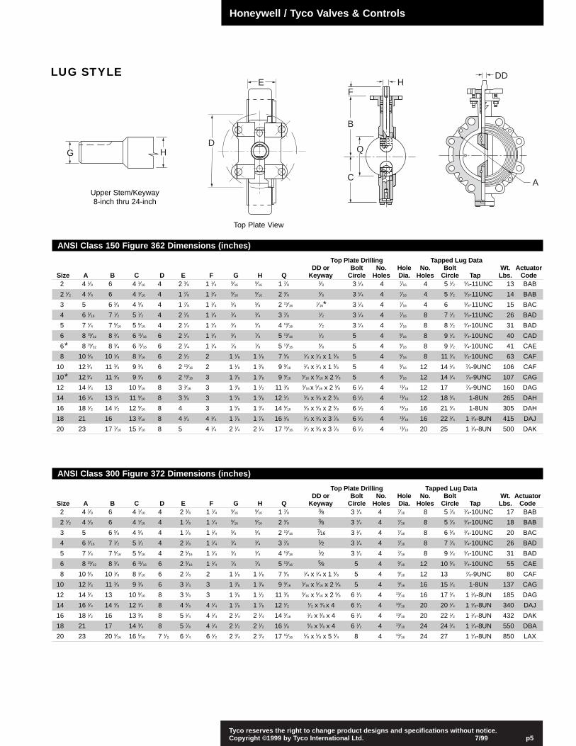
Top Plate View
LUG STYLE
ANSI Class 150 Figure 362 Dimensions (inches)
Top Plate Drilling Tapped Lug DataDD or Bolt No. Hole No. Bolt Wt. Actuator
Size A B C D E F G H Q Keyway Circle Holes Dia. Holes Circle Tap Lbs. Code2 4 1⁄8 6 4 1⁄16 4 2 3⁄8 1 1⁄4 9⁄16
9⁄16 1 7⁄8 3⁄8 3 1⁄4 4 7⁄16 4 5 1⁄2 5⁄8-11UNC 13 BAB
2 1⁄2 4 1⁄8 6 4 1⁄16 4 1 7⁄8 1 1⁄4 9⁄169⁄16 2 3⁄8 3⁄8 3 1⁄4 4 7⁄16 4 5 1⁄2 5⁄8-11UNC 14 BAB
3 5 6 5⁄8 4 5⁄8 4 1 7⁄8 1 1⁄4 5⁄8 5⁄8 2 15⁄167⁄16* 3 1⁄4 4 7⁄16 4 6 5⁄8-11UNC 15 BAC
4 6 3⁄16 7 1⁄2 5 1⁄2 4 2 1⁄8 1 1⁄4 3⁄4 3⁄4 3 7⁄8 1⁄2 3 1⁄4 4 7⁄16 8 7 1⁄2 5⁄8-11UNC 26 BAD
5 7 1⁄4 7 9⁄16 5 9⁄16 4 2 1⁄4 1 1⁄4 3⁄4 3⁄4 4 13⁄161⁄2 3 1⁄4 4 7⁄16 8 8 1⁄2 3⁄4-10UNC 31 BAD
6 8 19⁄32 8 3⁄4 6 11⁄16 6 2 1⁄4 1 1⁄4 3⁄4 7⁄8 5 13⁄161⁄2 5 4 9⁄16 8 9 1⁄2 3⁄4-10UNC 40 CAD
6* 8 19⁄32 8 3⁄4 6 11⁄16 6 2 1⁄4 1 1⁄4 7⁄8 7⁄8 5 13⁄165⁄8 5 4 9⁄16 8 9 1⁄2 3⁄4-10UNC 41 CAE
8 10 5⁄8 10 1⁄8 8 1⁄16 6 2 1⁄2 2 1 1⁄8 1 1⁄8 7 5⁄8 1⁄4 x 1⁄4 x 1 5⁄8 5 4 9⁄16 8 11 3⁄4 3⁄4-10UNC 63 CAF
10 12 3⁄4 11 3⁄8 9 3⁄8 6 2 13⁄16 2 1 1⁄8 1 3⁄8 9 9⁄161⁄4 x 1⁄4 x 1 5⁄8 5 4 9⁄16 12 14 1⁄4 7⁄8-9UNC 106 CAF
10* 12 3⁄4 11 3⁄8 9 3⁄8 6 2 13⁄16 3 1 3⁄8 1 3⁄8 9 9⁄165⁄16 x 5⁄16 x 2 5⁄8 5 4 9⁄16 12 14 1⁄4 7⁄8-9UNC 107 CAG
12 14 3⁄4 13 10 9⁄16 8 3 3⁄16 3 1 3⁄8 1 1⁄2 11 3⁄8 5⁄16 x 5⁄16 x 2 5⁄8 6 1⁄2 4 13⁄16 12 17 7⁄8-9UNC 160 DAG
14 16 1⁄4 13 1⁄4 11 9⁄16 8 3 5⁄8 3 1 5⁄8 1 5⁄8 12 1⁄2 3⁄8 x 3⁄8 x 2 5⁄8 6 1⁄2 4 13⁄16 12 18 3⁄4 1-8UN 265 DAH
16 18 1⁄2 14 1⁄2 12 9⁄16 8 4 3 1 5⁄8 1 3⁄4 14 5⁄163⁄8 x 3⁄8 x 2 5⁄8 6 1⁄2 4 13⁄16 16 21 3⁄4 1-8UN 305 DAH
18 21 16 13 3⁄16 8 4 1⁄2 4 1⁄4 1 7⁄8 1 7⁄8 16 1⁄8 1⁄2 x 3⁄8 x 3 7⁄8 6 1⁄2 4 13⁄16 16 22 3⁄4 1 1⁄8-8UN 415 DAJ
20 23 17 7⁄16 15 1⁄16 8 5 4 1⁄4 2 1⁄4 2 1⁄4 17 15⁄161⁄2 x 3⁄8 x 3 7⁄8 6 1⁄2 4 13⁄16 20 25 1 1⁄8-8UN 500 DAK
ANSI Class 300 Figure 372 Dimensions (inches)
Top Plate Drilling Tapped Lug DataDD or Bolt No. Hole No. Bolt Wt. Actuator
Size A B C D E F G H Q Keyway Circle Holes Dia. Holes Circle Tap Lbs. Code2 4 1⁄8 6 4 1⁄16 4 2 3⁄8 1 1⁄4 9⁄16
9⁄16 1 7⁄8 3⁄8 3 1⁄4 4 7⁄16 8 5 7⁄8 3⁄4-10UNC 17 BAB
2 1⁄2 4 1⁄8 6 4 1⁄16 4 1 7⁄8 1 1⁄4 9⁄169⁄16 2 3⁄8 3⁄8 3 1⁄4 4 7⁄16 8 5 7⁄8 3⁄4-10UNC 18 BAB
3 5 6 5⁄8 4 5⁄8 4 1 7⁄8 1 1⁄4 5⁄8 5⁄8 2 15⁄167⁄16 3 1⁄4 4 7⁄16 8 6 5⁄8 3⁄4-10UNC 20 BAC
4 6 3⁄16 7 1⁄2 5 1⁄2 4 2 1⁄8 1 1⁄4 3⁄4 3⁄4 3 7⁄8 1⁄2 3 1⁄4 4 7⁄16 8 7 7⁄8 3⁄4-10UNC 26 BAD
5 7 1⁄4 7 9⁄16 5 9⁄16 4 2 5⁄16 1 1⁄4 3⁄4 3⁄4 4 13⁄161⁄2 3 1⁄4 4 7⁄16 8 9 1⁄4 3⁄4-10UNC 31 BAD
6 8 19⁄32 8 3⁄4 6 11⁄16 6 2 5⁄16 1 1⁄4 7⁄8 7⁄8 5 13⁄165⁄8 5 4 9⁄16 12 10 5⁄8 3⁄4-10UNC 55 CAE
8 10 5⁄8 10 1⁄8 8 1⁄16 6 2 7⁄8 2 1 1⁄8 1 1⁄8 7 5⁄8 1⁄4 x 1⁄4 x 1 5⁄8 5 4 9⁄16 12 13 7⁄8-9UNC 80 CAF
10 12 3⁄4 11 3⁄8 9 3⁄8 6 3 1⁄4 3 1 3⁄8 1 3⁄8 9 9⁄165⁄16 x 5⁄16 x 2 5⁄8 5 4 9⁄16 16 15 1⁄4 1-8UN 137 CAG
12 14 3⁄4 13 10 9⁄16 8 3 5⁄8 3 1 3⁄8 1 1⁄2 11 3⁄8 5⁄16 x 5⁄16 x 2 5⁄8 6 1⁄2 4 13⁄16 16 17 3⁄4 1 1⁄8-8UN 185 DAG
14 16 1⁄4 14 3⁄8 12 1⁄4 8 4 5⁄8 4 1⁄4 1 7⁄8 1 7⁄8 12 1⁄2 1⁄2 x 3⁄8 x 4 6 1⁄2 4 13⁄16 20 20 1⁄4 1 1⁄8-8UN 340 DAJ
16 18 1⁄2 16 13 3⁄8 8 5 1⁄4 4 1⁄4 2 1⁄4 2 1⁄4 14 5⁄161⁄2 x 3⁄8 x 4 6 1⁄2 4 13⁄16 20 22 1⁄2 1 1⁄4-8UN 432 DAK
18 21 17 14 3⁄4 8 5 7⁄8 4 1⁄4 2 1⁄2 2 1⁄2 16 1⁄8 5⁄8 x 5⁄8 x 4 6 1⁄2 4 13⁄16 24 24 3⁄4 1 1⁄4-8UN 550 DBA
20 23 20 3⁄16 16 5⁄16 7 1⁄2 6 1⁄4 6 1⁄2 2 3⁄4 2 3⁄4 17 15⁄165⁄8 x 5⁄8 x 5 3⁄4 8 4 13⁄16 24 27 1 1⁄4-8UN 850 LAX
Upper Stem/Keyway8-inch thru 24-inch
G HD
EF
H
B
Q
C
DD
A
Honeywell / Tyco Valves & Controls
Tyco reserves the right to change product designs and specifications without notice.Copyright ©1999 by Tyco International Ltd. 7/99 p6
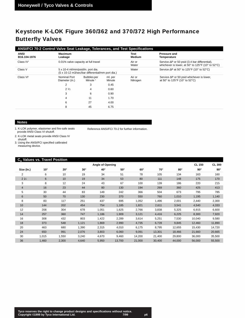
ANSI/FCI 70-2 Control Valve Seat Leakage, Tolerances, and Test SpecificationsANSI Maximum Test Pressure andB16.104-1976 Leakage Medium Temperature
Class IV2 0.01% valve capacity at full travel Air or Service ∆P or 50 psid (3.4 bar differential),Water whichever is lower, at 50° to 125°F (10° to 52°C)
Class V 5 x 10⁻⁴ ml/min/psid/in. port dia. Water Service ∆P at 50° to 125°F (10° to 52°C)(5 x 10-12 m3/sec/bar differential/mm port dia.)
Class VI1 Nominal Port Bubbles per ml. per Air or Service ∆P or 50 psid whichever is lower,Diameter (in.) Minute 3 Minute Nitrogen at 50° to 125°F (10° to 52°C)
2 3 0.45
2 1⁄2 4 0.60
3 6 0.90
4 11 1.70
6 27 4.00
8 45 6.75
Cv Values vs. Travel PositionAngle of Opening CL 150 CL 300
Size (In.) 10° 20° 30° 40° 50° 60° 70° 80° 90° 90°
2 6 10 19 34 51 78 105 134 163 160
2 1⁄2 6 10 19 34 53 80 111 148 175 170
3 8 12 24 43 67 100 139 186 220 215
4 16 23 44 80 130 194 269 360 425 413
5 30 44 83 149 242 366 504 673 795 785
6 50 70 130 230 370 550 760 1,010 1,195 1,140
8 83 117 251 437 695 1,052 1,496 2,001 2,440 2,300
10 144 202 454 754 1,185 1,821 2,611 3,541 4,540 4,333
12 208 304 678 1,051 1,625 2,766 3,838 5,325 6,915 6,600
14 257 360 747 1,186 1,909 3,121 4,416 6,225 8,300 7,920
16 308 432 803 1,422 2,289 3,614 5,251 7,530 10,040 9,580
18 373 548 1,121 1,869 2,990 4,735 6,728 9,845 12,460 11,890
20 463 680 1,390 2,315 4,010 6,175 8,795 12,655 15,430 14,720
24 650 991 2,076 3,803 6,060 9,091 13,301 18,466 21,660 20,665
30 1,015 1,550 3,240 4,670 9,460 14,200 21,400 29,800 36,000 35,500
36 1,460 2,300 4,640 5,950 13,700 21,000 30,400 44,000 56,000 55,500
Notes
1. K-LOK polymer, elastomer and fire-safe seats provide ANSI Class VI shutoff.
2. K-LOK metal seats provide ANSI Class IV shutoff.
3. Using the ANSI/FCI specified calibrated measuring device.
Reference ANSI/FCI 70-2 for further information.
Honeywell / Tyco Valves & Controls
Keystone K-LOK Figure 360/362 and 370/372 High Performance Butterfly Valves

Recommended Standards and SpecificationsANSI – B16.34 Steel valves
B31.1 Power piping
B31.3 Chemical plant and petroleum refinery piping
B16.5 Steel pipe flanges and flange fittings
MSS – SP-6 Standard finishes for pipe flanges
SP-25 Standard marking systems for valves
SP-55 Quality standard for steel casting
SP-61 Pressure testing of steel valves
SP-67 Butterfly valves
SP-68 High pressure offset disc butterfly valves
API – 609 Butterfly valves
607 Fire test for soft seated quarter-turn valves
598 Valve inspection and test
BS – 5146 Inspection and test of steel valves for the petroleum, petrochemical and allied industries
4504 Flanges and bolting for pipes, valves and fittings
DIN – 3230 Technical conditions of delivery for valves
ISO – 5752 Metal valves for use in flanged pipe systems
2084 Pipeline flanges for general use
JIS – 2215 Basic dimensions for steel pipe flanges
K-LOK® is a registered trademark of Tyco International
800
700
600
500
400
300
200
100
0-40 100 200 300 400 500
Pre
ssu
re (
PS
IG)
Temperature (°F)
NB
R
EP
DM
316 S.S.ANSI 300
316 S.S.ANSI 150
Carbon steelANSI 300
CarbonsteelANSI 150
Flu
oro
elas
tom
er(F
KM
)
Pressure/Temperature Ratings for Seat Materials
Elastomer Seats Polymer Seats
Tyco reserves the right to change product designs and specifications without notice.Copyright ©1999 by Tyco International Ltd. 7/99 p7
800
700
600
500
400
300
200
100
0-40 100 200 300 400 500
Pre
ssu
re (
PS
IG)
Temperature (°F)
Carbon steelANSI 300
316 S.S.ANSI 300
CarbonsteelANSI 150
316 S.S.ANSI 150
PT
FE
RT
FE
UH
MW
PE
Honeywell / Tyco Valves & Controls
Tyco reserves the right to change product designs and specifications without notice.Copyright ©1999 by Tyco International Ltd. 7/99 p8
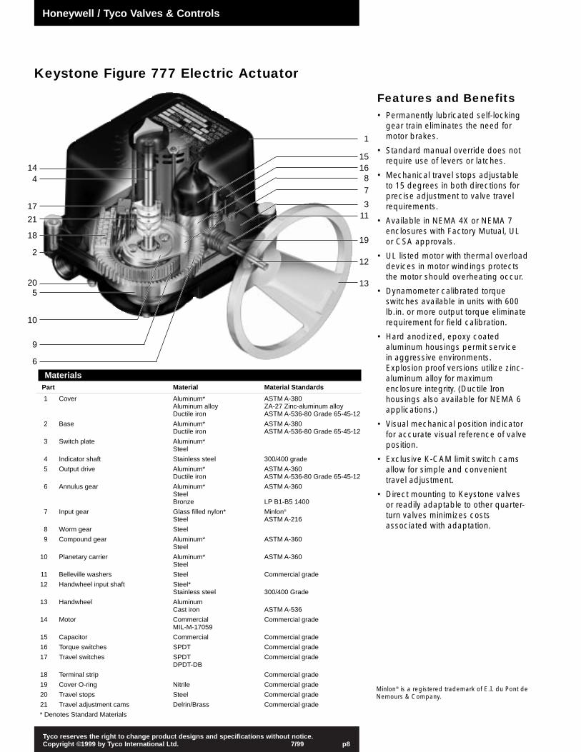
Keystone Figure 777 Electric Actuator
MaterialsPart Material Material Standards
1 Cover Aluminum* ASTM A-380Aluminum alloy ZA-27 Zinc-aluminum alloyDuctile iron ASTM A-536-80 Grade 65-45-12
2 Base Aluminum* ASTM A-380Ductile iron ASTM A-536-80 Grade 65-45-12
3 Switch plate Aluminum*Steel
4 Indicator shaft Stainless steel 300/400 grade
5 Output drive Aluminum* ASTM A-360Ductile iron ASTM A-536-80 Grade 65-45-12
6 Annulus gear Aluminum* ASTM A-360SteelBronze LP B1-B5 1400
7 Input gear Glass filled nylon* Minlon®
Steel ASTM A-216
8 Worm gear Steel
9 Compound gear Aluminum* ASTM A-360Steel
10 Planetary carrier Aluminum* ASTM A-360Steel
11 Belleville washers Steel Commercial grade
12 Handwheel input shaft Steel*Stainless steel 300/400 Grade
13 Handwheel AluminumCast iron ASTM A-536
14 Motor Commercial Commercial gradeMIL-M-17059
15 Capacitor Commercial Commercial grade
16 Torque switches SPDT Commercial grade
17 Travel switches SPDT Commercial gradeDPDT-DB
18 Terminal strip Commercial grade
19 Cover O-ring Nitrile Commercial grade
20 Travel stops Steel Commercial grade
21 Travel adjustment cams Delrin/Brass Commercial grade
* Denotes Standard Materials
144
17
21
18
2
205
10
9
6
1
1516
87
311
19
12
13
Minlon® is a registered trademark of E.I. du Pont deNemours & Company.
Features and Benefits• Permanently lubricated self-locking
gear train eliminates the need formotor brakes.
• Standard manual override does notrequire use of levers or latches.
• Mechanical travel stops adjustable to 15 degrees in both directions forprecise adjustment to valve travelrequirements.
• Available in NEMA 4X or NEMA 7enclosures with Factory Mutual, UL or CSA approvals.
• UL listed motor with thermal overloaddevices in motor windings protectsthe motor should overheating occur.
• Dynamometer calibrated torqueswitches available in units with 600lb.in. or more output torque eliminaterequirement for field calibration.
• Hard anodized, epoxy coatedaluminum housings permit service in aggressive environments.Explosion proof versions utilize zinc-aluminum alloy for maximumenclosure integrity. (Ductile Ironhousings also available for NEMA 6applications.)
• Visual mechanical position indicatorfor accurate visual reference of valveposition.
• Exclusive K-CAM limit switch camsallow for simple and convenienttravel adjustment.
• Direct mounting to Keystone valvesor readily adaptable to other quarter-turn valves minimizes costsassociated with adaptation.
Honeywell / Tyco Valves & Controls

Tyco reserves the right to change product designs and specifications without notice.Copyright ©1999 by Tyco International Ltd. 7/99 p9
Servo-amp Connection Adjustment ChartRemote Command Signal Servo-amp Wiring
Command Dip Switch Contacts to ActuatorSignal 1 2 3 4 Terminal Strip (TB-1)
Variable VDC – ON – – As shown in diagram
1-Phase Motor
T.P.G
Cap.
Red
Open TorqueSwitch
NCNO Com
Com
Open Limit Switch
NCNO
Com
NCNO
Aux. Open Limit Switch
Aux. Close Limit SwitchComNC
NO
Close Limit SwitchCom
NCNO
Close Torque Switch
ComNCNO
Blue
Heater(Optional)
G
G
Int. Pot.
RetransModule
TB-1
1-PhasePower Supply
LampSupply
HeaterSupply*
L N
N L
Variable 4-20mA*Output Signal
(24VDC Supply Required)
9 10 11 12 13 14 15 161 2 3 4 5 6 7 8
CCOS
O
F777 1PH Electric Actuator
TB-2
1-Phase Motor
G
Open Torque SwitchNCNO
ComCom
Open Limit Switch
NCNO
Com
NCNO
Aux. Open Limit Switch
Aux. Close Limit Switch
ComNCNO
Close Limit Switch
ComNCNO
F777 1PH Electric Actuator
G
G
Blue
T.P.
Cap.
RedClose Torque Switch
NCNO
Com
Int. Pot-1.
Servo-AmpModule
Blue
Blue
Red
RedC O N L
Heater
TB-1
LampSupply
1-PhasePower Supply
RemoteCommand
Signal
O C
1 2 3 4 5 6 7 8
LN
R1
4 3 2 1
Two Position Wiring Diagram AW-0018
Modulating Service Wiring Diagram AW-0162
Two Position and ModulatingRef. Description
C Close
CAP. Capacitor
G Ground
HEATER Anti-condensation heater withthermal cutout (optional)
INT. POT.-1 5K Ohm internal potentiometer toretransmission module
INT. POT.-2 5K Ohm internal potentiometerto retransmission module
L Live
N Neutral
O Open
R1 Command signal modificationresistor
S Stop
TB-1.2 8-way terminal block
T.P. Thermal protector (with auto reset)
Notes
1. Diagram drawn in mid-travel position.
2. Red wiring counterclockwise (open)direction.
3. Blue wiring clockwise (close) direction.
4. Customer/field wiring shown in dashedlines.
5. Remote position indication lamps canbe AC or DC supplied. For 1-phase connection, live wire must beconnected to TB-1/5 (TB-1/6 formodulating) (neutral must not beswitched).
6. (Modulating) On loss of commandsignal, actuator will run to its ‘closed’position. Diagram shown for variableDC remote command signal. The chartbelow shows the required dip switchsetting and wiring.
* Options
7. Remote relays must be used if multipleactuators are wired in parallel.
Honeywell / Tyco Valves & Controls
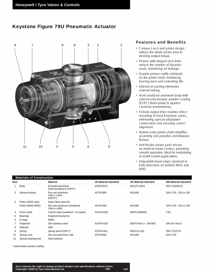
Features and Benefits• Compact rack and pinion design
utilizes the whole piston area todevelop output torque.
• Pistons with integral rack drivereduce the number of dynamic seals, minimizing air leakage.
• Double pistons nullify sideloads on the pinion shaft, minimizingbearing wear and extending life.
• Internal air porting eliminates external tubing.
• Hard anodized aluminum body withexternal electrostatic powder coating(ESPC) finish protects againstcorrosive environments.
• Female output drive enables directmounting of most Keystone valves,eliminating special adaptationconnections and assuring correctalignment.
• Bottom entry pinion shaft simplifiesassembly and provides anti-blowoutfeature.
• Anti-friction piston pads ensure no metal-to-metal contact, providingsmooth operation. Ideal for modulatingor on/off control applications.
• Adjustable travel stops standard inboth directions on models 065S and090S.
Tyco reserves the right to change product designs and specifications without notice.Copyright ©1999 by Tyco International Ltd. 7/99 p10
Materials of ConstructionItem Material US Material Standard UK Material Standard DIN Material Standard
1 Body Extruded aluminum ASTM B221 BS1474 6063 DIN 3.33206.51(hard anodized & ESPC*)
2 Spring housing Die-cast aluminum ASTM B85 BS1490 DIN 1725 - 230 or 226LM6 or LM24(ESPC*)
3 Piston (003S only) Glass filled nylon 66
Piston (006S-090S) Die-cast aluminum (anodized) ASTM B85 BS1490 DIN 1725 - 230 or 226LM6 or LM24
4 Pinion shaft Carbon steel (sealbond - N coated) ASTM A108 BS970 080M40 C40
5 Bearings Engineered polymer
6 O-rings Nitrile
7 Fasteners 304 stainless steel ASTM A193 BS970 Part 3 - 304/305 DIN 267 Part 3
8 Indicator ABS
9 Spring Spring steel (ESPC*) ASTM A401 BS5216 HS3 DIN 17223 Pti
10 Spring cone Die-cast aluminum LM6 ASTM B85 BS1490 DIN 1725
11 Spring retaining bolt Steel (plated)
* electrostatic powder coating
9 7 6 8 3 1 2
56541011
Keystone Figure 79U Pneumatic Actuator
Honeywell / Tyco Valves & Controls

Tyco reserves the right to change product designs and specifications without notice.Copyright ©1999 by Tyco International Ltd. 7/99 p11
Accessories
Pneumatic Modulating DoubleActing AssemblyValve positioning is proportionallycontrolled via a pneumatic signal for precise control of flow. AMastergear manual overrideprovides valve positioning in theevent of a loss of air supply.
Spring Fail Safe PneumaticAssemblyANSI Class 150# high performancebutterfly valves offer enhancedmaterials and engineering toprovide products for demandingapplications with elevated pressuresand temperatures. The pneumaticfail safe actuator offers fail open orclosed positioning in the event of power failure. The limit switchprovides position indication in thefull open/closed positions orintervals between.
Tyco Electro-PneumaticPositioner / Model EP5Valve positioning is controlled via anelectronic input signal of 4-20 mA.This signal is transduced to apneumatic control signal of 3-15 psi,providing proportional controlthrough the valve’s full range oftravel. Additional accessories willprovide position feedback of 4-20mA, resistive signal or endswitches.
Keystone Figure 222
Double ActingActuator
Pneumatic Positioner
K-Switch Limit Switch Enclosure
PneumaticFail OpenActuator
Figure 362 ANSI 150# High Performance Butterfly Valve
MastergearManual Override
Tyco Electro-Pneumatic Positioner
Keystone Figure 79U Actuator
Honeywell / Tyco Valves & Controls

Tyco reserves the right to change product designs and specifications without notice.Copyright ©1999 by Tyco International Ltd. 7/99 p12
2 Way 20 psi Assemblies - Dimensions - inches [mm] Valve Valve A B C D E F G H J L M NotesModel Size Valve Body CL Pipe to Face/Face Tap Size Bolt No. Actuator Actuator CL Stroke
Height O.D. Top Plate Circle Bolts Height Width Length Clearance
222 2 8.50 [216] 6.00 [153] 5.31 [135] 1.69 [43] .625-11 UNC-2B 4.75 [121] 4 7.5 [191] 6.88 [175] 18.00 [457] 5.0 [127] 1
222 2.5 9.31 [236] 6.75 [172] 5.98 [150] 1.81 [46] .625-11 UNC-2B 5.50 [140] 4 7.5 [191] 6.88 [175] 18.00 [457] 5.0 [127] 1
222 3 10.00 [254] 7.25 [184] 6.31 [160] 1.81 [46] .625-11 UNC-2B 6.00 [152] 4 7.5 [191] 6.88 [175] 18.00 [457] 5.0 [127] 2
222 3 10.00 [254] 7.25 [184] 6.31 [160] 1.81 [46] .625-11 UNC-2B 6.00 [152] 4 7.5 [191] 6.88 [175] 17.75 [451] 5.0 [127] 1 & 4
222 4 11.38 [288] 8.64 [223] 7.13 [180] 2.06 [52] .625-11 UNC-2B 7.50 [191] 4 7.5 [191] 6.88 [175] 17.75 [451] 5.0 [127] 1 & 4
222 5 12.68 [325] 10.00 [254] 7.69 [195] 2.25 [56] .750-10 UNC-2B 8.50 [216] 8 9.25 [235] 8.25 [210] 18.00 [457] 5.0 [127] 1 & 4
222 5 12.68 [325] 10.00 [254] 7.69 [195] 2.25 [56] .750-10 UNC-2B 8.50 [216] 8 7.5 [191] 6.88 [175] 17.75 [451] 5.0 [127] 2 & 4
222 6 13.94 [354] 11.00 [279] 8.31 [210] 2.25 [56] .750-10 UNC-2B 9.50 [241] 8 9.25 [235] 8.25 [210] 17.75[451] 5.0 [127] 1 & 4
222 6 13.94 [354] 11.00 [279] 8.31 [210] 2.25 [56] .750-10 UNC-2B 9.50 [241] 8 9.25 [235] 8.25 [210] 18.00 [457] 5.0 [127] 2 & 4
AR2 8 16.19 [411] 13.25 [336] 9.50 [240] 2.50 [64] .750-10 UNC-2B 11.75 [298] 8 9.25 [235] 8.25 [210] 17.75 [451] 7.5 [191] 3 & 4
AR2 10 19.00 [483] 15.88 [403] 10.75 [273] 2.50 [64] .875-9 UNC-2B 14.25 [362] 12 9.25 [235] 8.25 [210] 17.75 [451] 7.5 [191] 3 & 4
AR2 12 21.63 [549] 18.63 [473] 12.25 [311] 3.00 [76] .875-9 UNC-2B 17.00 [432] 12 9.25 [235] 8.25 [210] 17.75 [451] 7.5 [191] 3 & 4
Two-way Valve Assemblies - 20 psi Pneumatic Spring Return
Notes
1. Assembly is rated for 200 psi shutoff pressure.2. Assembly is rated for 100 psi shutoff pressure.3. Assembly is rated for 50 psi shutoff pressure.4. Two actuators are included in assembly.
2, 2.5, 3, 5, 6-inch 3—6-inch 8—12-inch*
Honeywell / Tyco Valves & Controls
H
C
A
EFG
B Dia.
J
D
MMinimum AllowableClearance for Arm Stroke
L
H
C
A
EFG
B Dia.
J
L
D
MMinimum AllowableClearance for Arm Stroke
H
C
A
EFG
B Dia.
J
L
D
MMinimum AllowableClearance for Arm Stroke
Tyco reserves the right to change product designs and specifications without notice.Copyright ©1999 by Tyco International Ltd. 7/99 p13
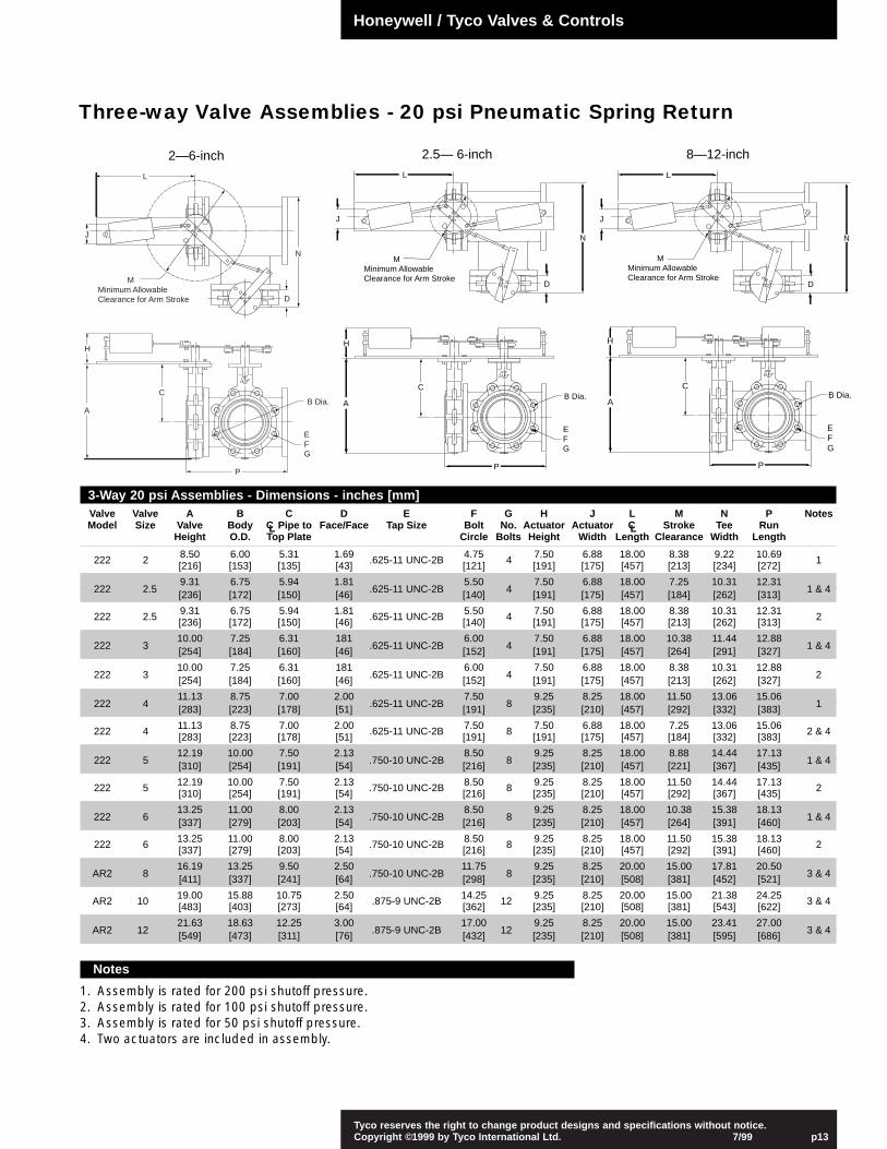
Three-way Valve Assemblies - 20 psi Pneumatic Spring Return
2.5— 6-inch2—6-inch 8—12-inch
Notes
1. Assembly is rated for 200 psi shutoff pressure.2. Assembly is rated for 100 psi shutoff pressure.3. Assembly is rated for 50 psi shutoff pressure.4. Two actuators are included in assembly.
Honeywell / Tyco Valves & Controls
P
B Dia.
EFG
C
A
H
D
J
N
L
MMinimum AllowableClearance for Arm Stroke
P
B Dia.
EFG
C
A
H
D
J
N
L
MMinimum AllowableClearance for Arm Stroke
P
B Dia.
EFG
C
A
H
D
J
N
L
MMinimum AllowableClearance for Arm Stroke
3-Way 20 psi Assemblies - Dimensions - inches [mm] Valve Valve A B C D E F G H J L M N P NotesModel Size Valve Body CL Pipe to Face/Face Tap Size Bolt No. Actuator Actuator CL Stroke Tee Run
Height O.D. Top Plate Circle Bolts Height Width Length Clearance Width Length
222 2 8.50 6.00 5.31 1.69 .625-11 UNC-2B 4.75 4 7.50 6.88 18.00 8.38 9.22 10.69 1[216] [153] [135] [43] [121] [191] [175] [457] [213] [234] [272]
9.31 6.75 5.94 1.81 5.50 7.50 6.88 18.00 7.25 10.31 12.31222 2.5 [236] [172] [150] [46] .625-11 UNC-2B [140] 4 [191] [175] [457] [184] [262] [313] 1 & 4
222 2.5 9.31 6.75 5.94 1.81 .625-11 UNC-2B 5.50 4 7.50 6.88 18.00 8.38 10.31 12.31 2[236] [172] [150] [46] [140] [191] [175] [457] [213] [262] [313]
10.00 7.25 6.31 181 6.00 7.50 6.88 18.00 10.38 11.44 12.88222 3 [254] [184] [160] [46] .625-11 UNC-2B [152] 4 [191] [175] [457] [264] [291] [327] 1 & 4
10.00 7.25 6.31 181 6.00 7.50 6.88 18.00 8.38 10.31 12.88222 3 [254] [184] [160] [46] .625-11 UNC-2B [152] 4 [191] [175] [457] [213] [262] [327] 2
11.13 8.75 7.00 2.00 7.50 9.25 8.25 18.00 11.50 13.06 15.06222 4 [283] [223] [178] [51] .625-11 UNC-2B [191] 8 [235] [210] [457] [292] [332] [383] 1
222 4 11.13 8.75 7.00 2.00 .625-11 UNC-2B 7.50 8 7.50 6.88 18.00 7.25 13.06 15.06 2 & 4[283] [223] [178] [51] [191] [191] [175] [457] [184] [332] [383]
12.19 10.00 7.50 2.13 8.50 9.25 8.25 18.00 8.88 14.44 17.13222 5 [310] [254] [191] [54] .750-10 UNC-2B [216] 8 [235] [210] [457] [221] [367] [435] 1 & 4
222 5 12.19 10.00 7.50 2.13 .750-10 UNC-2B 8.50 8 9.25 8.25 18.00 11.50 14.44 17.13 2[310] [254] [191] [54] [216] [235] [210] [457] [292] [367] [435]
13.25 11.00 8.00 2.13 8.50 9.25 8.25 18.00 10.38 15.38 18.13222 6 [337] [279] [203] [54] .750-10 UNC-2B [216] 8 [235] [210] [457] [264] [391] [460] 1 & 4
222 6 13.25 11.00 8.00 2.13 .750-10 UNC-2B 8.50 8 9.25 8.25 18.00 11.50 15.38 18.13 2[337] [279] [203] [54] [216] [235] [210] [457] [292] [391] [460]
16.19 13.25 9.50 2.50 11.75 9.25 8.25 20.00 15.00 17.81 20.50AR2 8 [411] [337] [241] [64] .750-10 UNC-2B [298] 8 [235] [210] [508] [381] [452] [521] 3 & 4
AR2 10 19.00 15.88 10.75 2.50 .875-9 UNC-2B 14.25 12 9.25 8.25 20.00 15.00 21.38 24.25 3 & 4[483] [403] [273] [64] [362] [235] [210] [508] [381] [543] [622]
21.63 18.63 12.25 3.00 17.00 9.25 8.25 20.00 15.00 23.41 27.00AR2 12 [549] [473] [311] [76] .875-9 UNC-2B [432] 12 [235] [210] [508] [381] [595] [686] 3 & 4

Honeywell / Tyco Valves & Controls
Tyco reserves the right to change product designs and specifications without notice.Copyright ©1999 by Tyco International Ltd. 7/99 p14
DCA Two-way Valve Assemblies / H1 – H7 Series Actuators
Electric Non-Spring Return
5—6-inch
Electric Spring Return
2—4-inch 4-inch2—3-inch
D
LK
J
H
EFG
B Dia.
C
A
D
LK
J
H
EFG
B Dia.
C
A
H2
H
EFG
B Dia.
C
A
D
LK
J
D
LK
J
H
EFG
B Dia.
C
A
H2
2-Way Electric Non Spring Return Valve Dimensions - inches [mm] Valve Valve A B C D E F G H J K LModel Size Valve Body CL Pipe to Face/Face Tap Size Bolt No. Actuator Actuator Actuator CL
Height O.D. Top Plate Circle Bolts Height Width Length to Rear
222 2 8.50 [216] 6.00 [153] 5.31 [135] 1.69 [43] .625-11 UNC-2B 4.75 [121] 4 3.40 [87] 4.00 [102] 9.50 [241] 7.50 [191]
222 2.5 9.31 [236] 6.75 [172] 5.94 [150] 1.81 [46] .625-11 UNC-2B 5.50 [140] 4 3.40 [87] 4.00 [102] 9.50 [241] 7.50 [191]
222 3 10.00 [254] 7.25 [184] 6.31 [160] 1.81 [46] .625-11 UNC-2B 6.00 [152] 4 3.40 [87] 4.00 [102] 9.50 [241] 7.50 [191]
222 4 11.38 [288] 8.81 [223] 7.13 [180] 2.06 [52] .625-11 UNC-2B 7.50 [191] 8 3.40 [87] 4.00 [102] 9.50 [241] 7.50 [191]
222 5* 12.18 [310] 10.00 [254] 7.50 [191] 2.13 [54] .750-10 UNC-2B 8.50 [216] 8 3.40 [87] 4.00 [102] 13.34 [339] 11.34 [288]
222 6* 13.25 [337] 11.00 [279] 8.00 [203] 2.13 [54] .750-10 UNC-2B 9.50 [241] 8 3.40 [87] 4.00 [102] 13.34 [339] 11.34 [288]
* For 5” and 6 ” (Dual actuators) the H2 dimension is 7.41 [189].
2-Way Electric Spring Return Valve Dimensions - inches [mm] Valve Valve A B C D E F G H J K LModel Size Valve Body CL Pipe to Face/Face Tap Size Bolt No. Actuator Actuator Actuator CL
Height O.D. Top Plate Circle Bolts Height Width Length to Rear
222 2 8.50 [216] 6.00 [153] 5.31 [135] 1.69 [43] .625-11 UNC-2B 4.75 [121] 4 3.25 [83] 4.00 [102] 10.34 [263] 8.34 [212]
222 2.5 9.31 [236] 6.75 [172] 5.94 [150] 1.81 [46] .625-11 UNC-2B 5.50 [140] 4 3.25 [83] 4.00 [102] 10.34 [263] 8.34 [212]
222 3 10.00 [254] 7.25 [184] 6.31 [160] 1.81 [46] .625-11 UNC-2B 6.00 [152] 4 3.25 [83] 4.00 [102] 10.34 [263] 8.34 [212]
222 4 11.38 [288] 8.81 [223] 7.13 [180] 2.06 [52] .625-11 UNC-2B 7.50 [191] 8 3.25 [83] 4.00 [102] 14.84 [377] 12.84 [327]
* For 4” (Dual actuators) the H2 dimension is 7.00 [179].
Notes
1. Assembly is rated for 200 psi shutoff pressure.2. Assembly is rated for 100 psi shutoff pressure.3. Assembly is rated for 50 psi shutoff pressure.
All assemblies are rated for 100 psi shutoff pressure

Honeywell / Tyco Valves & Controls
Tyco reserves the right to change product designs and specifications without notice.Copyright ©1999 by Tyco International Ltd. 7/99 p15
DCA Three-way Valve Assemblies / H1 – H7 Series Actuators
2—4-inch
Electric Non-Spring Return
2—2.5-inch
Electric Spring Return
5—6-inch 3—4-inch
H
EFG
B Dia.A
C
P
MMinimum AllowableClearance forArm Stroke
J
D
K
L
N
MMinimum AllowableClearance forArm Stroke
J
D
K
L
N
H
EFG
B Dia.A
C
P
H2
MMinimum AllowableClearance forArm Stroke
J
D
K
L
N
H
EFG
B Dia.A
C
P
MMinimum AllowableClearance forArm Stroke
J
D
K
L
N
H
EFG
B Dia.A
C
P
H2
3-Way Electric Non Spring Return Valve Dimensions - inches [mm] Valve Valve A B C D E F G H J K L M N PModel Size Valve Body CL Pipe to Face/Face Tap Size Bolt No. Actuator Actuator Actuator CL Stroke Tee Run
Height O.D. Top Plate Circle Bolts Height Width Length Length Clearance Width Length
222 2 8.50 6.00 5.31 1.69 .625-11 UNC-2B 4.75 4 3.41 4.00 11.84 7.50 7.25 9.22 10.69[216] [153] [135] [43] [121] [87] [102] [301] [191] [184] [234] [272]
9.31 6.75 5.94 1.81 5.50 3.41 4.00 13.41 7.50 7.25 10.31 12.31222 2.5 [236] [172] [150] [46] .625-11 UNC-2B [140] 4 [87] [102] [341] [191] [184] [262] [313]
222 3 10.00 7.25 6.31 1.81 .625-11 UNC-2B 6.00 4 3.41 4.00 13.98 7.50 7.25 11.44 12.88[254] [184] [160] [46] [152] [87] [102] [355] [191] [184] [291] [327]
11.13 8.75 7.00 2.00 7.50 3.41 4.00 16.06 7.50 7.25 13.06 15.06222 4 [283] [222] [178] [51] .625-11 UNC-2B [191] 8 [87] [102] [408] [191] [184] [332] [383]
222 5* 12.19 10.00 7.50 2.13 .750-10 UNC-2B 8.50 8 3.41 4.00 18.06 11.34 8.69 14.44 17.13[310] [254] [191] [54] [216] [87] [102] [459] [288] [221] [435] [435]
13.25 11.00 8.00 2.13 9.50 3.41 4.00 19.06 11.34 10.38 15.38 18.13222 6* [337] [279] [203] [54] .750-10 UNC-2B [241] 8 [87] [102] [484] [288] [264] [391] [460]
* For 5” and 6 ” (Dual actuators) the H2 dimension is 7.41 [198].
3-Way Electric Spring Return Valve Dimensions - inches [mm] Valve Valve A B C D E F G H J K L M N PModel Size Valve Body CL Pipe to Face/Face Tap Size Bolt No. Actuator Actuator Actuator CL Stroke Tee Run
Height O.D. Top Plate Circle Bolts Height Width Length Length Clearance Width Length
222 2 8.50 6.00 5.31 1.69 .625-11 UNC-2B 4.75 4 3.25 4.00 11.84 8.34 7.25 9.22 10.69[216] [153] [135] [43] [121] [83] [102] [301] [212] [184] [234] [272]
9.31 6.75 5.94 1.81 5.50 3.25 4.00 13.41 8.34 7.25 10.31 12.31222 2.5 [236] [172] [150] [46] .625-11 UNC-2B [140] 4 [83] [102] [341] [212] [184] [262] [313]
222 3* 10.00 7.25 6.31 1.81 .625-11 UNC-2B 6.00 4 3.25 4.00 13.98 8.34 7.25 11.44 12.88[254] [184] [160] [46] [152] [83] [102] [355] [212] [184] [291] [327]
11.13 8.75 7.00 2.00 7.50 3.25 4.00 16.06 8.34 7.25 13.06 15.06222 4* [283] [222] [178] [51] .625-11 UNC-2B [191] 8 [83] [102] [408] [212] [184] [332] [383]
* For 3” and 4 ” (Dual actuators) the H2 dimension is 7.00 [178].
All assemblies are rated for 100 psi shutoff pressure
Tyco reserves the right to change product designs and specifications without notice.Copyright ©1999 by Tyco International Ltd. 7/99 p16
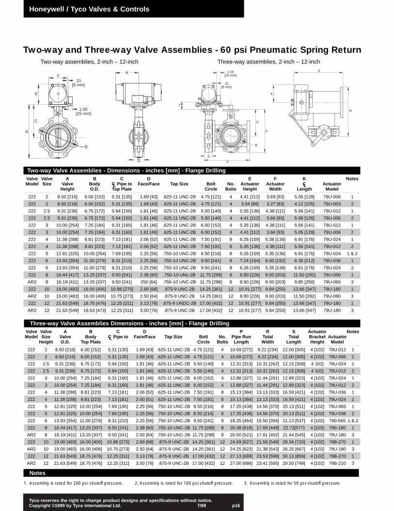
Two-way and Three-way Valve Assemblies - 60 psi Pneumatic Spring ReturnThree-way assemblies, 2-inch – 12-inchTwo-way assemblies, 2-inch – 12-inch
Three-way Valve Assemblies Dimensions - inches [mm] - Flange Drilling Valve Valve A B C D P R S Actuator NotesModel Size Valve Body CL Pipe to Face/Face Tap Size Bolt No. Pipe Run Total Total Bracket Actuator
Height O.D. Top Plate Circle Bolts Length Width Length Height Model
222 2 8.50 [216] 6.00 [152] 5.31 [135] 1.69 [43] .625-11 UNC-2B 4.75 [121] 4 10.69 [272] 9.22 [234] 12.00 [305] 4 [102] 79U-012 1
222 2 8.50 [216] 6.00 [152] 5.31 [135] 1.69 [43] .625-11 UNC-2B 4.75 [121] 4 10.69 [272] 9.22 [234] 12.00 [305] 4 [102] 79U-006 2
222 2.5 9.31 [236] 6.75 [172] 5.94 [150] 1.81 [46] .625-11 UNC-2B 5.50 [140] 4 12.31 [313] 10.31 [262] 12.15 [308] 4 102] 79U-024 1
222 2.5 9.31 [236] 6.75 [172] 5.94 [150] 1.81 [46] .625-11 UNC-2B 5.50 [140] 4 12.31 [313] 10.31 [262] 12.15 [308] 4 102] 79U-012 2
222 3 10.00 [254] 7.25 [184] 6.31 [160] 1.81 [46] .625-11 UNC-2B 6.00 [152] 4 12.88 [327] 11.44 [291] 12.89 [323] 4 [102] 79U-024 1
222 3 10.00 [254] 7.25 [184] 6.31 [160] 1.81 [46] .625-11 UNC-2B 6.00 [152] 4 12.88 [327] 11.44 [291] 12.89 [323] 4 [102] 79U-012 2
222 4 11.38 [288] 8.81 [223] 7.13 [181] 2.06 [52] .625-11 UNC-2B 7.50 [191] 8 15.13 [384] 13.13 [333] 16.59 [421] 4 [102] 79U-036 1
222 4 11.38 [288] 8.81 [223] 7.13 [181] 2.00 [51] .625-11 UNC-2B 7.50 [191] 8 15.13 [384] 13.13 [333] 16.59 [421] 4 [102] 79U-024 2
222 5 12.81 [325] 10.00 [254] 7.69 [195] 2.25 [56] .750-10 UNC-2B 8.50 [216] 8 17.25 [438] 14.56 [370] 20.13 [511] 4 [102] 79U-065 1
222 5 12.81 [325] 10.00 [254] 7.69 [195] 2.25 [56] .750-10 UNC-2B 8.50 [216] 8 17.25 [438] 14.56 [370] 20.13 [511] 4 [102] 79U-036 2
222 6 13.93 [354] 11.00 [279] 8.31 [210] 2.25 [56] .750-10 UNC-2B 9.50 [241] 8 18.25 [464] 15.50 [394] 21.13 [537] 4 [102] 790-065 1 & 2
222 8 16.44 [417] 13.25 [337] 9.50 [241] 2.38 [60] .750-10 UNC-2B 11.75 [298] 8 20.38 [518] 17.69 [449] 22.72[577] 4 [102] 790-180 1
AR2 8 16.19 [411] 13.25 [337] 9.50 [241] 2.50 [64] .750-10 UNC-2B 11.75 [298] 8 20.50 [521] 17.81 [452] 21.44 [545] 4 [102] 79U-180 3
222 10 19.00 [483] 16.00 [406] 10.88 [275] 2.69 [68] .875-9 UNC-2B 14.25 [361] 12 24.69 [627] 21.56 [548] 28.34 [720] 4 [102] 79B-270 1
AR2 10 19.00 [483] 16.00 [406] 10.75 [273] 2.50 [64] .875-9 UNC-2B 14.25 [361] 12 24.25 [622] 21.38 [543] 26.25 [667] 4 [102] 79U-180 3
222 12 21.63 [549] 18.75 [476] 12.25 [311] 3.13 [78] .875-9 UNC-2B 17.00 [432] 12 27.13 [689] 23.53 [598] 30.13 [859] 4 [102] 79B-270 1
AR2 12 21.63 [549] 18.75 [476] 12.25 [311] 3.00 [76] .875-9 UNC-2B 17.00 [432] 12 27.00 [686] 23.41 [595] 29.50 [749] 4 [102] 79B-210 3
B
A
C
K
D
.31[8 mm]
1.00[25 mm]
E
F
T
C
A
P
B
D
.31[8 mm]
1.00[25 mm]
S
R
K
Honeywell / Tyco Valves & Controls
Two-way Valve Assemblies - Dimensions - inches [mm] - Flange Drilling Valve Valve A B C D E F K NotesModel Size Valve Body CL Pipe to Face/Face Tap Size Bolt No. Actuator Actuator CL Actuator
Height O.D. Top Plate Circle Bolts Height Width Length Model
222 2 8.50 [216] 6.00 [152] 5.31 [135] 1.69 [43] .625-11 UNC-2B 4.75 [121] 4 4.41 [112] 3.69 [93] 5.05 [128] 79U-006 1
222 2 8.50 [216] 6.00 [152] 5.31 [135] 1.69 [43] .625-11 UNC-2B 4.75 [121] 4 3.54 [89] 3.27 [83] 4.12 [105] 79U-003 2
222 2.5 9.31 [236] 6.75 [172] 5.94 [150] 1.81 [46] .625-11 UNC-2B 5.50 [140] 4 5.35 [136] 4.38 [111] 5.56 [141] 79U-012 1
222 2.5 9.31 [236] 6.75 [172] 5.94 [150] 1.81 [46] .625-11 UNC-2B 5.50 [140] 4 4.41 [112] 3.66 [93] 5.06 [126] 79U-006 2
222 3 10.00 [254] 7.25 [184] 6.31 [160] 1.81 [46] .625-11 UNC-2B 6.00 [152] 4 5.35 [136] 4.38 [111] 5.56 [141] 79U-012 1
222 3 10.00 [254] 7.25 [184] 6.31 [160] 1.81 [46] .625-11 UNC-2B 6.00 [152] 4 4.41 [112] 3.66 [93] 5.05 [128] 79U-006 2
222 4 11.38 [288] 8.81 [223] 7.13 [181] 2.06 [52] .625-11 UNC-2B 7.50 [191] 8 6.26 [159] 5.38 [136] 6.91 [176] 79U-024 1
222 4 11.38 [288] 8.81 [223] 7.13 [181] 2.06 [52] .625-11 UNC-2B 7.50 [191] 8 5.35 [136] 4.38 [111] 5.56 [141] 79U-012 2
222 5 12.81 [325] 10.00 [254] 7.69 [195] 2.25 [56] .750-10 UNC-2B 8.50 [216] 8 6.26 [159] 5.35 [136] 6.91 [176] 79U-024 1 & 2
222 6 13.93 [354] 11.00 [279] 8.31 [210] 2.25 [56] .750-10 UNC-2B 9.50 [241] 8 7.24 [164] 6.00 [152] 8.35 [212] 79U-036 1
222 6 13.93 [354] 11.00 [279] 8.31 [210] 2.25 [56] .750-10 UNC-2B 9.50 [241] 8 6.26 [159] 5.35 [136] 6.91 [176] 79U-024 2
222 8 16.44 [417] 13.25 [337] 9.50 [241] 2.38 [60] .750-10 UNc-2B 11.75 [298] 8 8.90 [226] 8.00 [203] 11.50 [292] 79U-090 1
AR2 8 16.19 [411] 13.25 [337] 9.50 [241] 250 [64] .750-10 UNC-2B 11.75 [298] 8 8.90 [226] 8.00 [203] 9.85 [250] 79U-065 3
222 10 19.00 [483] 16.00 [406] 10.88 [275] 2.69 [68] .875-9 UNC-2B 14.25 [361] 12 10.91 [277] 9.84 [250] 13.66 [347] 79U-180 1
AR2 10 19.00 [483] 16.00 [406] 10.75 [273] 2.50 [64] .875-9 UNC-2B 14.25 [361] 12 8.90 [226] 8.00 [203] 11.50 [292] 79U-090 3
222 12 21.63 [549] 18.75 [476] 12.25 [311] 3.13 [78] .875-9 UNDC-2B 17.00 [432] 12 10.91 [277] 9.84 [250] 13.66 [347] 79U-180 1
AR2 12 21.63 [549] 18.63 [473] 12.25 [311] 3.00 [76] .875-9 UNC-2B 17.00 [432] 12 10.91 [277] 9.84 [250] 13.66 [347] 79U-180 3
Notes
1. Assembly is rated for 200 psi shutoff pressure. 2. Assembly is rated for 100 psi shutoff pressure. 3. Assembly is rated for 50 psi shutoff pressure.

Tyco reserves the right to change product designs and specifications without notice.Copyright ©1999 by Tyco International Ltd. 7/99 p17
Two-way assemblies, 2-inch – 12-inch Three-way assemblies, 2-inch – 12-inch
Two-way and Three-way Valve Assemblies - 60 psi Pneumatic Double Acting
B
A
C
.31[8 mm]
1.00[25 mm]
E
F J
D
S
R
J
.31[8 mm]
1.00[25 mm]
T
C
A
P
B
F
D
Honeywell / Tyco Valves & Controls
Three-way Valve Assemblies Dimensions - inches [mm] - Flange Drilling Valve Valve A B C D P R S Actuator NotesModel Size Valve Body CL Pipe to Face/Face Tap Size Bolt No. Pipe Run Total Total Bracket Actuator
Height O.D. Top Plate Circle Bolts Length Width Length Height Model
222 2 8.50 [216] 6.00 [152] 5.31 [135] 1.69 [43] .625-11 UNC-2B 4.75 [121] 4 10.69 [272] 9.22 [234] 12.00 [305] 4 [102] 79U-006 1 & 2
222 2.5 9.31 [236] 6.75 [172] 5.94 [150] 1.81 [46] .625-11 UNC-2B 5.50 [140] 4 12.31 [313] 10.31 [262] 12.15 [308] 4 102] 79U-006 1 & 2
222 3 10.00 [254] 7.25 [184] 6.31 [160] 1.81 [46] .625-11 UNC-2B 6.00 [152] 4 12.88 [327] 11.44 [291] 12.89 [323] 4 [102] 79U-006 1 & 2
222 4 11.38 [288] 8.81 [223] 7.13 [181] 2.06 [52] .625-11 UNC-2B 7.50 [191] 8 15.13 [384] 13.13 [333] 16.59 [421] 4 [102] 79U-012 1
222 4 11.38 [288] 8.81 [223] 7.13 [181] 2.06 [52] .625-11 UNC-2B 7.50 [191] 8 15.13 [384] 13.13 [333] 16.59 [421] 4 [102] 79U-006 2
222 5 12.81 [325] 10.00 [254] 7.69 [195] 2.25 [56] .750-10 UNC-2B 8.50 [216] 8 17.25 [438] 14.56 [370] 20.13 [511] 4 [102] 79U-024 1
222 5 12.81 [325] 10.00 [254] 7.69 [195] 2.25 [56] .750-10 UNC-2B 8.50 [216] 8 17.25 [438] 14.56 [370] 20.13 [511] 4 [102] 79U-012 2
222 6 13.93 [354] 11.00 [279] 8.31 [210] 2.25 [56] .750-10 UNC-2B 9.50 [241] 8 18.25 [464] 15.50 [394] 21.13 [537] 4 [102] 79U-024 1
222 6 13.93 [354] 11.00 [279] 8.31 [210] 2.25 [56] .750-10 UNC-2B 9.50 [241] 8 18.25 [464] 15.50 [394] 21.13 [537] 4 [102] 79U-012 2
222 8 16.44 [417] 13.25 [337] 9.50 [241] 2.38 [60] .750-10 UNC-2B 11.75 [298] 8 20.38 [518] 17.69 [449] 22.72[577] 4 [102] 79U-085 1
AR2 8 16.19 [411] 13.25 [337] 9.50 [241] 2.50 [64] .750-10 UNC-2B 11.75 [298] 8 20.50 [521] 17.81 [452] 21.44 [545] 4 [102] 79U-036 3
222 10 19.00 [483] 16.00 [406] 10.88 [275] 2.69 [68] .875-9 UNC-2B 14.25 [361] 12 24.69 [627] 21.56 [548] 28.34 [720] 4 [102] 79U-090 1
AR2 10 19.00 [483] 16.00 [406] 10.75 [273] 2.50 [64] .875-9 UNC-2B 14.25 [361] 12 24.25 [622] 21.38 [543] 26.25 [667] 4 [102] 79U-065 3
222 12 21.63 [549] 18.75 [476] 12.25 [311] 3.13 [78] .875-9 UNC-2B 17.00 [432] 12 27.13 [689] 23.53 [598] 33.81 [859] 4 [102] 79U-180 1
AR2 12 21.63 [549] 18.75 [476] 12.25 [311] 3.00 [76] .875-9 UNC-2B 17.00 [432] 12 27.00 [686] 23.41 [595] 29.50 [749] 4 [102] 79U-065 3
Two-way Valve Assemblies - Dimensions - inches [mm] - Flange Drilling Valve Valve A B C D E F J NotesModel Size Valve Body CL Pipe to Face/Face Tap Size Bolt No. Actuator Actuator Actuator Actuator
Height O.D. Top Plate Circle Bolts Height Width Length Model
222 2 8.50 [216] 6.00 [152] 5.31 [135] 1.69 [43] .625-11 UNC-2B 4.75 [121] 4 3.54 [90] 3.27 [83] 5.57 [141] 79U-003 1 & 2
222 2.5 9.31 [236] 6.75 [172] 5.94 [150] 1.81 [46] .625-11 UNC-2B 5.50 [140] 4 3.54 [90] 3.27 [83] 5.57 [141] 79U-003 1 & 2
222 3 10.00 [254] 7.25 [184] 6.31 [160] 1.81 [46] .625-11 UNC-2B 6.00 [152] 4 4.41 [112] 3.66 [93] 6.55 [166] 79U-006 1
222 3 10.00 [254] 7.25 [184] 6.31 [160] 1.81 [46] .625-11 UNC-2B 6.00 [152] 4 3.54 [90] 3.27 [83] 5.57 [141] 79U-003 2
222 4 11.38 [288] 8.81 [223] 7.13 [181] 2.06 [52] .625-11 UNC-2B 7.50 [191] 8 4.41 [112] 3.66 [93] 6.55 [166] 79U-006 1 & 2
222 5 12.81 [325] 10.00 [254] 7.69 [195] 2.25 [56] .750-10 UNC-2B 8.50 [216] 8 5.35 [136] 4.38 [111] 7.13 [181] 79U-012 1
222 5 12.81 [325] 10.00 [254] 7.69 [195] 2.25 [56] .750-10 UNC-2B 8.50 [216] 8 4.41 [112] 3.66 [93] 6.55 [166] 79U-005 2
222 6 13.93 [354] 11.00 [279] 8.31 [210] 2.25 [56] .750-10 UNC-2B 9.50 [241] 8 6.26 [159] 5.35 [136] 9.17 [233] 79U-024 1
222 6 13.93 [354] 11.00 [279] 8.31 [210] 2.25 [56] .750-10 UNC-2B 9.50 [241] 8 5.35 [136] 4.38 [111] 7.13 [181] 79U-012 2
222 8 16.44 [417] 13.25 [337] 9.50 [241] 2.38 [60] .750-10 UNC-2B 11.75 [298] 8 7.24 [184] 6.00 [152] 10.72 [272] 79U-036 1
AR2 8 16.44 [417] 13.25 [337] 9.50 [241] 250 [64] .750-10 UNC-2B 11.75 [298] 8 6.26 [156] 5.35 [138] 9.17 [233] 79U-024 3
222 10 19.00 [483] 16.00 [406] 10.88 [275] 2.69 [68] .875-9 UNC-2B 14.25 [361] 12 8.90 [226] 8.00 [203] 12.78 [325] 79U-065 1
AR2 10 19.00 [483] 16.00 [406] 10.75 [273] 2.50 [64] .875-9 UNC-2B 14.25 [361] 12 7.24 [184] 6.00 [152] 10.72 [272] 79U-035 3
222 12 21.63 [549] 18.75 [476] 12.25 [311] 3.13 [78] .875-9 UNC-2B 17.00 [432] 12 8.90 [226] 8.00 [203] 16.06 [408] 79U-090 1
AR2 12 21.63 [549] 18.75 [476] 12.25 [311] 3.00 [76] .875-9 UNC-2B 17.00 [432] 12 8.90 [2267] 8.00 [203] 12.78 [325] 79U-065 3
Notes
1. Assembly is rated for 200 psi shutoff pressure. 2. Assembly is rated for 100 psi shutoff pressure. 3. Assembly is rated for 50 psi shutoff pressure.

Tyco reserves the right to change product designs and specifications without notice.Copyright ©1999 by Tyco International Ltd. 7/99 p18
Two-way and Three-way Electric Actuated Valves
Two-way assemblies, 2-inch – 12-inch Three-way assemblies, 2-inch – 12-inch
Notes1. 14-inch – 20-inch, consult factory.
2. For complete assembly details, consult mastercatalog or contact the factory.
* 50 psi shutoff pressure.
B
A
C
E
M G
H
J
OPEN
CLOSE
K
D
C
A
P
B
S
R
D
T
Honeywell / Tyco Valves & Controls
Two-way Valve Assemblies - Dimensions - inches [mm] Valve Valve A B C D E G H K NotesModel Size Valve Body CL Pipe to Face/Face Actuator Pipe CL H.W. Total Actuator
Height O.D. to Top Plate Height to H.W. Dia. Width Model
222 2 8.50 [216] 6.00 [152] 5.31 [135] 1.69 [43] 7.72 [196] 4.54 [115] 5.00 [127] 7.88 [200] EPI 3 1 & 2
222 2.5 9.31 [236] 6.75 [172] 5.94 [150] 1.81 [46] 7.72 [196] 4.54 [115] 5.00 [127] 7.88 [200] EPI 3 1 & 2
222 3 10.00 [254] 7.25 [184] 6.31 [160] 1.81 [46] 9.60 [244] 6.50 [165] 8.00 [203] 10.94 [278] EPI 6 1 & 2
222 4 11.38 [288] 8.81 [223] 7.13 [181] 2.06 [52] 9.60 [244] 6.50 [165] 8.00 [203] 10.94 [278] EPI 6 1 & 2
222 5 12.81 [325] 10.00 [254] 7.69 [195] 2.25 [56] 9.60 [244] 6.50 [165] 8.00 [203] 10.94 [276] EPI 13 1 & 2
222 6 13.93 [354] 11.00 [279] 8.31 [210] 2.25 [56] 13.00 [330] 8.25 [210] 12.00 [305] 15.06 [383] EPI 36 1
222 6 13.93 [354] 11.00 [279] 8.31 [210] 2.25 [56] .9.60 [244] 6.50 [165] 8.00 [203] 10.94 [278] EPI 13 2
222 8 16.44 [417] 13.25 [337] 9.50 [241] 2.38 [60] 13.00 [330] 8.25 [210] 12.00 [305] 15.06 [383] EPI 36 1
AR2 8 16.19 [411] 13.25 [337] 9.50 [241] 250 [64] 13.00 [330] 8.25 [210] 12.00 [305] 15.06 [383] EPI 36 3
222 10 19.00 [483] 16.00 [406] 10.88 [275] 2.69 [68] 17.33 [440] 8.25 [210 12.00 [305] 23.38 [594] EPI 91 1
AR2 10 19.00 [483] 16.00 [406] 10.75 [273] 2.50 [64] 13.00 [330] 8.25 [210] 12.00 [305] 15.06 [383] EPI 36 3
222 12 21.63 [549] 18.75 [476] 12.25 [311] 3.13 [78] 17.33 [440] 8.25 [210] 12.00 [305] 23.38 [594] EPI 91 1
AR2 12 21.63 [549] 18.75 [476] 12.25 [311] 3.00 [76] 13.00 [330] 8.25 [210] 12.00 [305] 15.06 [383] EPI 51 3
Three-way Valve Assemblies Dimensions - inches [mm] - Flange Drilling / Valves Only Valve Valve A B C D P R S Actuator NotesModel Size Valve Body CL Pipe to Face/Face Tap Size Bolt No. Pipe Run Total Total Bracket Actuator
Height O.D. Top Plate Circle Bolts Length Width Length Height Model
222 2 8.50 [216] 6.00 [152] 5.31 [135] 1.69 [43] .625-11 UNC-2B 4.75 [121] 4 10.69 [272] 9.22 [234] 12.00 [305] 4 [102] EPI 3 1 & 2
222 2.5 9.31 [236] 6.75 [172] 5.94 [150] 1.81 [46] .625-11 UNC-2B 5.50 [140] 4 12.31 [313] 10.31 [262] 12.15 [308] 4 102] EPI 6 1
222 2.5 9.31 [236] 6.75 [172] 5.94 [150] 1.81 [46] .625-11 UNC-2B 5.50 [140] 4 12.31 [313] 10.31 [262] 12.15 [308] 4 102] EPI 3 2
222 3 10.00 [254] 7.25 [184] 6.31 [160] 1.81 [46] .625-11 UNC-2B 6.00 [152] 4 12.88 [327] 11.44 [291] 12.89 [323] 4 [102] EPI 6 1
222 3 10.00 [254] 7.25 [184] 6.31 [160] 1.81 [46] .625-11 UNC-2B 6.00 [152] 4 12.88 [327] 11.44 [291] 12.89 [323] 4 [102] EPI 3 2
222 4 11.38 [288] 8.81 [223] 7.13 [181] 2.06 [52] .625-11 UNC-2B 7.50 [191] 8 15.13 [384] 13.13 [333] 16.59 [421] 4 [102] EPI 13 1
222 4 11.38 [288] 8.81 [223] 7.13 [181] 2.06 [52] .625-11 UNC-2B 7.50 [191] 8 15.13 [384] 13.13 [333] 16.59 [421] 4 [102] EPI 6 2
222 5 12.81 [325] 10.00 [254] 7.69 [195] 2.25 [56] .750-10 UNC-2B 8.50 [216] 8 17.25 [438] 14.56 [370] 20.13 [511] 4 [102] EPI 13 1 & 2
222 6 13.93 [354] 11.00 [279] 8.31 [210] 2.25 [56] .750-10 UNC-2B 9.50 [241] 8 18.25 [464] 15.50 [394] 21.13 [537] 4 [102] EPI 36 1
222 6 13.93 [354] 11.00 [279] 8.31 [210] 2.25 [56] .750-10 UNC-2B 9.50 [241] 8 18.25 [464] 15.50 [394] 21.13 [537] 4 [102] EPI 13 2
222 8 16.44 [417] 13.25 [337] 9.50 [241] 2.38 [60] .750-10 UNC-2B 11.75 [298] 8 20.38 [518] 17.69 [449] 22.72[577] 4 [102] EPI 51 1
AR2 8 16.19 [411] 13.25 [337] 9.50 [241] 2.50 [64] .750-10 UNC-2B 11.75 [298] 8 20.50 [521] 17.81 [452] 21.44 [545] 4 [102] EPI 36 3
222 10 19.00 [483] 16.00 [406] 10.88 [275] 2.69 [68] .875-9 UNC-2B 14.25 [361] 12 24.69 [627] 21.56 [548] 28.34 [720] 4 [102] EPI 91 1
AR2 10 19.00 [483] 16.00 [406] 10.75 [273] 2.50 [64] .875-9 UNC-2B 14.25 [361] 12 24.25 [622] 21.36 [543] 26.25 [667] 4 [102] EPI 51 3
222 12 21.63 [549] 18.75 [476] 12.25 [311] 3.13 [78] .875-9 UNC-2B 17.00 [432] 12 27.13 [689] 23.53 [598] 33.81 [859] 4 [102] EPI 91 1
AR2 12 21.63 [549] 18.75 [476] 12.25 [311] 3.00 [76] .875-9 UNC-2B 17.00 [432] 12 27.00 [686] 23.41 [595] 29.50 [749] 4 [102] EPI 51 3
Notes
1. Assembly is rated for 200 psi shutoff pressure. 2. Assembly is rated for 100 psi shutoff pressure. 3. Assembly is rated for 50 psi shutoff pressure.

100%
90%
80%
70%
60%
50%
40%
30%
20%
10%
0%
0% 20% 40% 60% 80% 100%100% 80% 60% 40% 20% 0%
Tyco reserves the right to change product designs and specifications without notice.Copyright ©1999 by Tyco International Ltd. 7/99 p19
Flow Coefficients
Figure AR1, AR2, 222 and 221 ValvesAngle of Disc Opening
Valve Size 10˚ 20˚ 30˚ 40˚ 50˚ 60˚ 70˚ 80˚ 90˚
2 – 1.3 5 14 26 40 52 59 60
21/2 – 1.4 6 21 44 74 107 138 151
3 0.7 1.5 8 29 67 115 175 234 262
4 1.7 15 48 107 196 318 463 589 647
5 3 32 99 206 362 579 832 1045 1141
6 4 47 145 295 510 810 1160 1450 1580
8 6 84 239 450 751 1190 1754 2385 2892
10 9 133 360 652 1064 1683 2524 3596 4593
12 12 192 509 899 1449 2288 3470 5085 6682
14 75 340 770 1400 2200 3400 5600 7900 10000
16 100 440 1000 1800 2800 4500 7400 10800 13000
18 130 570 1300 2300 3600 5800 9600 15000 18000
20 150 710 1600 2900 4600 7200 12000 18400 22000
Three-Way Valve Assembly Cv, Corrected for Tee Losses - Total, Both ValvesRun -> 0° 10° 20° 30° 40° 50° 60° 70° 80° 90°Branch -> 90° 80° 70° 60° 50° 40° 30° 20° 10° 0°Valve Size
2 54 53 49 43 38 40 44 52 57 58
21/2 114 108 93 74 52 64 78 102 126 135
3 188 178 148 114 55 95 120 165 210 229
4 385 374 348 313 150 295 345 419 482 511
5 642 627 600 563 270 549 630 740 829 870
6 935 909 867 809 483 780 895 1051 1180 1242
8 1688 1573 1424 1271 796 1175 1367 1661 1994 2254
10 2667 2430 2132 1856 1142 1685 1971 2439 3046 3570
12 3938 3531 3019 2579 1629 2312 2715 3401 4368 5240
14 5109 4825 4416 3719 2433 3514 3992 5259 6342 7173
16 6735 6462 5832 4904 3213 4498 5265 6943 8567 9410
18 9060 8724 7650 6372 4433 5778 6815 9056 11695 12785
20 11229 10799 9545 7901 5619 7339 8449 11309 14423 15770
Percent Branch Valve OpenPercent Run Valve Open
Per
cent
Ful
l Flo
w(b
ased
on
max
. te
e flo
w,
run
= 9
0°an
d br
anch
= 0
°)
6-inch AR1/AR2 at Constant Valve Differential Pressure (corrected for tee
Mixing
Branch Leg
Run Leg
Notes
1. Three-way valve assemblies Cv’s arecorrected from published two-wayCv’s to account for line lossesgenerated by the tee, and arecalculated values only. The pipefriction losses are a function of fluidvelocity through the pipe and thethree-way Cv’s listed are apparent forfull flow through the pipe. Operationat less than full capacity (lowervelocity) will increase the actual Cv’s.
2. The chart is based on percentagesand will reflect any valves Cv’s whentwo butterfly valves are installed on atee. This includes all Keystone Valvesand all other manufacturer’s valves.The percentages are only a reflectionof the tee losses.
Honeywell / Tyco Valves & Controls

Tyco reserves the right to change product designs and specifications without notice.Copyright ©1999 by Tyco International Ltd. 7/99 p20
Torque Data
Valve Torque Data (seating and unseating)Valve Valve Differential PressureModel Size 50 psi 100 psi 150 psi 200 psi 250 psi
(inches) in.lbs. Nm. in.lbs. Nm. in.lbs. Nm. in.lbs. Nm. in.lbs. Nm.
222 2 147 [16.61] 154 [17.40] 162 [18.30] 171 [19.32] 178 [20.11]
222-u/c 2 70 [7.91] 77 [8.70] — — — — — —
222 21/2 192 [21.69] 206 [23.27] 218 [24.63] 231 [26.10] 243 [27.46]
222-u/c 21/2 93 [10.51] 103 [11.64] — — — — — —
222 3 228 [25.76] 246 [27.79] 264 [29.82] 282 [31.86] 300 [33.90]
222-u/c 3 111 [12.54] 126 [14.24] — — — — — —
222 4 359 [40.56] 395 [44.62] 430 [48.58] 466 [52.65] 501 [56.60]
222-u/c 4 178 [20.11] 207 [23.38] — — — — — —
222 5 600 [67.79] 668 [75.47] 734 [82.93] 799 [90.28] 866 [97.85]
222-u/c 5 300 33.89 355 [40.10] — — — — — —
222 6 798 [90.16] 893 [100.90] 989 [111.74] 1085 [122.59] 1180 [133.32]
222-u/c 6 401 [45.30] 481 [54.34] — — — — — —
222 8 2070 [233.88] 2268 [256.25] 2466 [278.62] 2664 [300.99] 2862 [323.36]
AR2-u/c 8 1110 [125.41] — — — — — — — —
222 10 3567 [403.02] 4964 [560.86] 4362 [492.84] 4761 [537.92] 5158 [582.78]
AR2-u/c 10 1721 [194.45] — — — — — — — —
222 12 4173 [471.49] 4746 [536.23] 5319 [600.97] 5892 [665.71] 6465 [730.45]
AR2-u/c 12 2318 [261.90] — — — — — — — —
AR2 14 5147 [581.53] 5995 [677.35] 6842 [773.04] — — — —
AR2-u/c 14 3747 [423.35] — — — — — — — —
AR2 16 6808 [769.20] 8116 [916.99] 9424 [1064.77] — — — —
AR2-u/c 16 5008 [565.83] — — — — — — — —
AR2 18 8810 [995.40] 10720 [1211.20] 12630 [1427.00] — — — —
AR2-u/c 18 6610 [746.83] — — — — — — — —
AR2 20 11172 [1262.27] 13845 [1564.28] 16517 [1866.17] — — — —
AR2-u/c 20 8372 [945.91] — — — — — — — —
Electric Actuator Output TorqueOutput Torque Time for 90˚ Travel Current Locked
Actuator 2- Position Modulating 2-position Modulating Full Load Rotor AmpModel in.lbs. Nm. in.lbs. Nm. (sec) (sec) (amp) Draw
EPI-3 300 [33.89] 240 [27.12] 17 18–54 0.5 0.6
EPI-6 600 [67.79] 480 [54.23] 23 22–66 0.7 1.2
EPI-13 1300 [146.8] 1040 [117.50] 21 22–66 1.1 1.3
EPI-36 3600 [406.75] 2880 [325.38] 22 23–69 1.2 6.0
EPI-51 5100 [576.22] 4080 [460.96] 22 23–69 2.1 6.0
EPI-91 9100 [1028.16] 7280 [823.49] 60 61–183 2.0 6.0
EPI-151 15100 [1706.07] 12080 [1364.80] 60 61-183 2.5 6.0
Pneumatic Double Acting ActuatorsActuator Air Supply Pressure
Model 60 psi 80 psi 100 psi 120 psiin.lbs. Nm. in.lbs. Nm. in.lbs. Nm. in.lbs. Nm.
79U-003 240 [27.12] 325 [36.72] 409 [46.21] 493 [55.70]
79U-006 459 [51.86] 621 [70.16] 782 [88.35] 943 [106.54]
79U-012 893 [100.90] 1207 [136.37] 1520 [171.74] 1834 [207.21]
79U-024 1785 [201.68] 2411 [272.41] 3038 [343.25] 3884 [413.98]
79U-036 2668 [301.44] 3604 [407.20] 4540 [512.95] 5476 [618.71]
79U-065 5157 [582.66] 6966 [787.05] 8775 [991.44] 10585 [1195.95]
79U-090 6550 [740.05] 8848 [999.69] 11146 [1259.33] 13444 [1518.97]
79U-180 13458 [1520.48] 18180 [2053.98] 22402 [2587.47] 27270 [3080.96]
Honeywell / Tyco Valves & Controls

Tyco reserves the right to change product designs and specifications without notice.Copyright ©1999 by Tyco International Ltd. 7/99 p21
Pneumatic Spring Return ActuatorsActuator Air Supply Pressure
Model 60 psi 80 psi 100 psiin.lbs. Nm. in.lbs. Nm. in.lbs. Nm.
79U-003 SST 162 [18.30] 221 [24.97] 279 [31.52]
79U-003 SET 100 [11.30] 137 [15.48] 174 [19.66]
79U-003 AST 27 [14.35] 175 [19.77] 222 [25.08]
79U-003 AET 65 [7.34] 91 [10.28] 117 [13.22]
79U-006 SST 312 [35.25] 425 [48.02] 538 [60.79]
38U-006 SET 197 [22.26] 272 [30.73] 346 [39.09]
79U-006 AST 238 [26.89] 325 [36.72] 412 [46.55]
79U-006 AET 123 [13.90] 172 [19.43] 220 [24.86]
79U-012 SST 616 [69.60] 836 [94.46] 1058 [119.54]
79U-012 SET 391 [44.18] 536 [60.56] 709 [80.11]
79U-012 AST 455 [51.41] 624 [70.50] 764 [86.32]
79U-012 AET 295 [33.33] 324 [36.61] 415 [46.89]
79U-024 SST 1221 [137.95] 1660 [187.56] 2098 [237.04]
79U-024 SET 771 [87.11] 1059 [119.65] 1347 [152.19]
79U-024 AST 920 [103.95] 1258 [142.14] 1597 [180.44]
79U-024 AET 470 [53.10] 657 [74.23] 846 [95.59]
79U-036 SST 1794 [202.70] 2438 [275.46] 3083 [348.33]
79U-36 SET 1149 [129.82] 1579 [178.40] 2006 [226.65]
79U-036 AST 1379 [155.81] 1885 [212.98] 2392 [270.26]
79U-036 AET 734 [82.93] 1026 [115.92] 1317 [148.80]
79U-065 SST 3530 [398.84] 4578 [517.25] 6064 [685.14]
79U-065 SET 2226 [251.50] 3059 [345.62] 3892 [439.74]
79U-065 AST 2660 [300.54] 3636 [410.81] 4612 [521.09]
79U-065 AET 1356 [153.21] 2117 [239.19] 2440 [275.68]
79U-091 SST 4484 [506.62] 6093 [688.42] 7703 [870.32]
79U-091 SET 2827 [319.41] 3885 [438.95] 4943 [558.48]
79U-091 AST 3378 [381.66] 4618 [521.76] 5858 [661.87]
79U-091 AET 1721 [194.45] 2410 [272.29] 3098 [350.03]
79U-180 SST 9212 [1040.77] 12518 [1414.28] 15825 [1787.91]
79U-180 SET 5810 [656.41] 7983 [901.92] 10155 [1147.31]
79U-180 AST 6938 [783.86] 9487 [1071.84] 12036 [1359.83]
79U-180 AET 3537 [399.61] 4952 [559.48] 6367 [719.34]
Torque Data
Honeywell / Tyco Valves & Controls
Tyco reserves the right to change product designs and specifications without notice.Copyright ©1999 by Tyco International Ltd. 7/99 p22
Honeywell / Tyco Valves & Controls
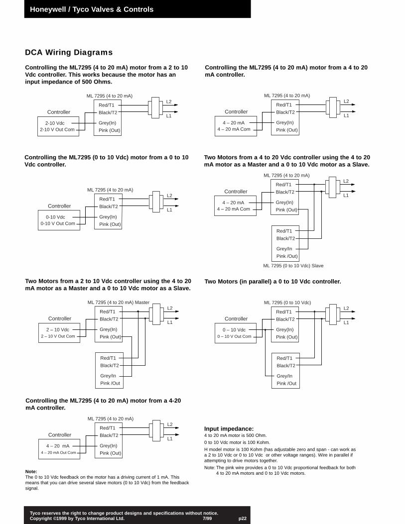
Input impedance:4 to 20 mA motor is 500 Ohm.
0 to 10 Vdc motor is 100 Kohm.
H model motor is 100 Kohm (has adjustable zero and span - can work as a 2 to 10 Vdc or 0 to 10 Vdc or other voltage ranges). Wire in parallel if attempting to drive motors together.
Note: The pink wire provides a 0 to 10 Vdc proportional feedback for both 4 to 20 mA motors and 0 to 10 Vdc motors.
DCA Wiring Diagrams
Controlling the ML7295 (4 to 20 mA) motor from a 2 to 10Vdc controller. This works because the motor has aninput impedance of 500 Ohms.
Controlling the ML7295 (4 to 20 mA) motor from a 4 to 20mA controller.
Controlling the ML7295 (0 to 10 Vdc) motor from a 0 to 10Vdc controller.
Two Motors from a 4 to 20 Vdc controller using the 4 to 20mA motor as a Master and a 0 to 10 Vdc motor as a Slave.
Two Motors from a 2 to 10 Vdc controller using the 4 to 20mA motor as a Master and a 0 to 10 Vdc motor as a Slave.
Two Motors (in parallel) a 0 to 10 Vdc controller.
Controlling the ML7295 (4 to 20 mA) motor from a 4-20mA controller.
Controller
L2
L1
2-10 Vdc2-10 V Out Com
Red/T1
Black/T2
Grey(In)
Pink (Out)
ML 7295 (4 to 20 mA)
Controller
L2
L1
4 – 20 mA4 – 20 mA Com
Red/T1
Black/T2
Grey(In)
Pink (Out)
ML 7295 (4 to 20 mA)
Controller
L2
L1
0-10 Vdc0-10 V Out Com
Red/T1
Black/T2
Grey(In)
Pink (Out)
ML 7295 (4 to 20 mA) Controller
L2
L1
4 – 20 mA4 – 20 mA Com
Red/T1
Black/T2
Grey(In)
Pink (Out)
ML 7295 (4 to 20 mA)
Red/T1
Black/T2
Grey/In
Pink /Out)
ML 7295 (0 to 10 Vdc) Slave
Controller
L2
L1
2 – 10 Vdc2 – 10 V Out Com
Red/T1
Black/T2
Grey(In)
Pink (Out)
ML 7295 (4 to 20 mA) Master
Red/T1
Black/T2
Grey/In
Pink /Out
Controller
L2
L1
0 – 10 Vdc0 – 10 V Out Com
Red/T1
Black/T2
Grey(In)
Pink (Out)
ML 7295 (0 to 10 Vdc)
Red/T1
Black/T2
Grey/In
Pink /Out
Controller
L2
L1
4 – 20 mA4 – 20 mA Out Com
Red/T1
Black/T2
Grey(In)
Pink (Out)
ML 7295 (4 to 20 mA)
Note: The 0 to 10 Vdc feedback on the motor has a driving current of 1 mA. Thismeans that you can drive several slave motors (0 to 10 Vdc) from the feedbacksignal.
Honeywell / Tyco Valves & Controls
Tyco reserves the right to change product designs and specifications without notice.Copyright ©1999 by Tyco International Ltd. 7/99 p23
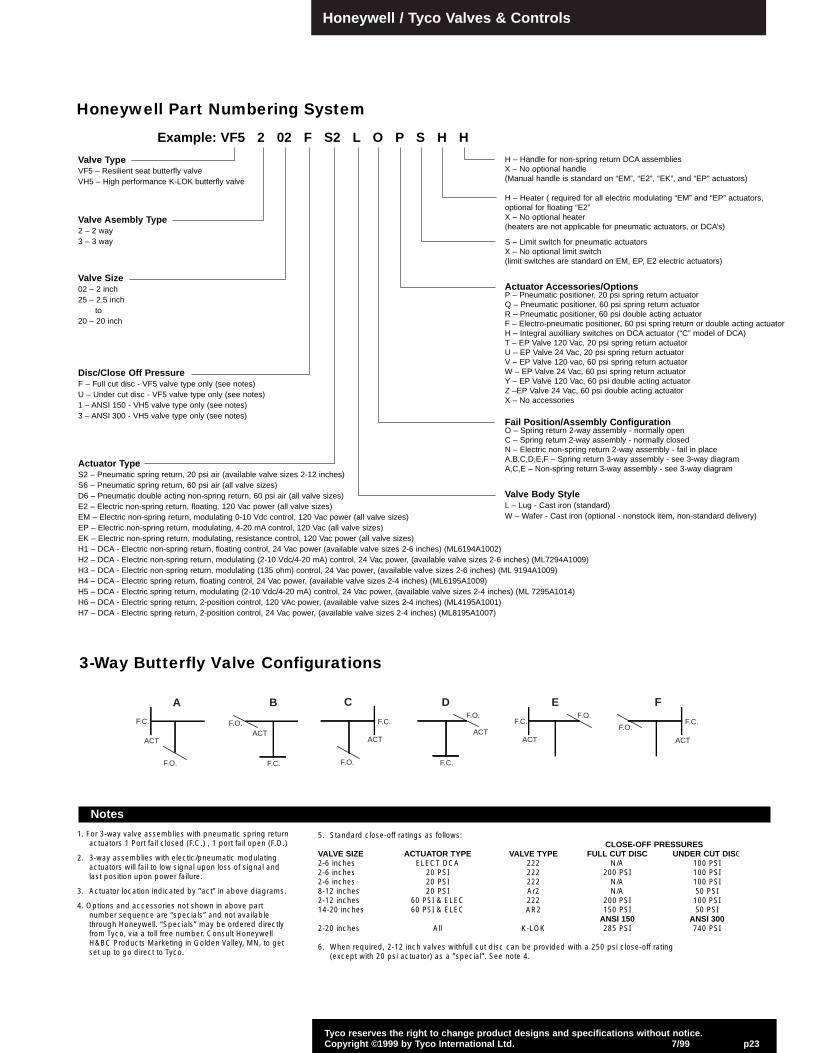
Honeywell Part Numbering System
1. For 3-way valve assemblies with pneumatic spring returnactuators 1 Port fail closed (F.C.) , 1 port fail open (F.O.)
2. 3-way assemblies with electic/pneumatic modulatingactuators will fail to low signal upon loss of signal andlast position upon power failure.
3. Actuator location indicated by ”act” in above diagrams.
4. Options and accessories not shown in above partnumber sequence are “specials” and not availablethrough Honeywell. “Specials” may be ordered directlyfrom Tyco, via a toll free number. Consult HoneywellH&BC Products Marketing in Golden Valley, MN, to getset up to go direct to Tyco.
Notes
5. Standard close-off ratings as follows:CLOSE-OFF PRESSURES
VALVE SIZE ACTUATOR TYPE VALVE TYPE FULL CUT DISC UNDER CUT DISC2-6 inches ELECT DCA 222 N/A 100 PSI2-6 inches 20 PSI 222 200 PSI 100 PSI2-6 inches 20 PSI 222 N/A 100 PSI8-12 inches 20 PSI Ar2 N/A 50 PSI2-12 inches 60 PSI & ELEC 222 200 PSI 100 PSI14-20 inches 60 PSI & ELEC AR2 150 PSI 50 PSI
ANSI 150 ANSI 3002-20 inches All K-LOK 285 PSI 740 PSI
6. When required, 2-12 inch valves withfull cut disc can be provided with a 250 psi close-off rating (except with 20 psi actuator) as a ”special”. See note 4.
Valve TypeVF5 – Resilient seat butterfly valveVH5 – High performance K-LOK butterfly valve
Valve Asembly Type2 – 2 way3 – 3 way
Valve Size02 – 2 inch25 – 2.5 inch
to20 – 20 inch
Disc/Close Off PressureF – Full cut disc - VF5 valve type only (see notes)U – Under cut disc - VF5 valve type only (see notes)1 – ANSI 150 - VH5 valve type only (see notes)3 – ANSI 300 - VH5 valve type only (see notes)
Actuator TypeS2 – Pneumatic spring return, 20 psi air (available valve sizes 2-12 inches)S6 – Pneumatic spring return, 60 psi air (all valve sizes)D6 – Pneumatic double acting non-spring return, 60 psi air (all valve sizes)E2 – Electric non-spring return, floating. 120 Vac power (all valve sizes)EM – Electric non-spring return, modulating 0-10 Vdc control, 120 Vac power (all valve sizes)EP – Electric non-spring return, modulating, 4-20 mA control, 120 Vac (all valve sizes)EK – Electric non-spring return, modulating, resistance control, 120 Vac power (all valve sizes)H1 – DCA - Electric non-spring return, floating control, 24 Vac power (available valve sizes 2-6 inches) (ML6194A1002)H2 – DCA - Electric non-spring return, modulating (2-10 Vdc/4-20 mA) control, 24 Vac power, (available valve sizes 2-6 inches) (ML7294A1009)H3 – DCA - Electric non-spring return, modulating (135 ohm) control, 24 Vac power, (available valve sizes 2-6 inches) (ML 9194A1009)H4 – DCA - Electric spring return, floating control, 24 Vac power, (available valve sizes 2-4 inches) (ML6195A1009)H5 – DCA - Electric spring return, modulating (2-10 Vdc/4-20 mA) control, 24 Vac power, (available valve sizes 2-4 inches) (ML 7295A1014)H6 – DCA - Electric spring return, 2-position control, 120 VAc power, (available valve sizes 2-4 inches) (ML4195A1001)H7 – DCA - Electric spring return, 2-position control, 24 Vac power, (available valve sizes 2-4 inches) (ML8195A1007)
Valve Body StyleL – Lug - Cast iron (standard)W – Wafer - Cast iron (optional - nonstock item, non-standard delivery)
Fail Position/Assembly ConfigurationO – Spring return 2-way assembly - normally openC – Spring return 2-way assembly - normally closedN – Electric non-spring return 2-way assembly - fail in placeA.B,C,D,E,F – Spring return 3-way assembly - see 3-way diagramA,C,E – Non-spring return 3-way assembly - see 3-way diagram
Actuator Accessories/OptionsP – Pneumatic positioner, 20 psi spring return actuatorQ – Pneumatic positioner, 60 psi spring return actuatorR – Pneumatic positioner, 60 psi double acting actuatorF – Electro-pneumatic positioner, 60 psi spring return or double acting actuatorH – Integral auxilliary switches on DCA actuator (“C” model of DCA)T – EP Valve 120 Vac, 20 psi spring return actuatorU – EP Valve 24 Vac, 20 psi spring return actuatorV – EP Valve 120 vac, 60 psi spring return actuatorW – EP Valve 24 Vac, 60 psi spring return actuatorY – EP Valve 120 Vac, 60 psi double acting actuatorZ –EP Valve 24 Vac, 60 psi double acting actuatorX – No accessories
S – Limit switch for pneumatic actuatorsX – No optional limit switch(limit switches are standard on EM, EP, E2 electric actuators)
H – Heater ( required for all electric modulating “EM” and “EP” actuators,optional for floating “E2”X – No optional heater(heaters are not applicable for pneumatic actuators, or DCA’s)
Example: VF5 2 02 F S2 L O P S H H
H – Handle for non-spring return DCA assembliesX – No optional handle(Manual handle is standard on “EM”, “E2”, “EK”, and “EP” actuators)
3-Way Butterfly Valve Configurations
F.C.
F.O.
ACT
A
F.C.
ACTF.O.
B
F.C.
F.O.
ACT
CF.O.
ACT
F.C.
D
F.C.
ACT
F.O.
E
F.O.
ACT
F.C.
F
Honeywell / Tyco Valves & Controls
Tyco reserves the right to change product designs and specifications without notice.Copyright ©1999 by Tyco International Ltd. 7/99 p24
The data presented in this bulletin is for general information only. Manufacturer is not responsible for acceptability of these products in relation to system requirements.Patents and Patents Pending in U.S. and foreign countries. All rights reserved. Printed in U.S.A. Tyco reserves the right to change product designs and specificationswithout notice. © Copyright 1999.
Tyco Valves & Controls: 1102 Howard Avenue Deer Park, TX 77536Phone: (888) 930-9355FAX: (281) 930-0166
HONEYWELL FORM 63-2557
By using this Honeywell literature, you agree that Honeywell will have no liability for any damages arising out of your use or modification to, the literature. You will defend and indemnify Honeywell, its affiliates and subsidiaries, from and against any liability, cost, or damages, including attorneys’ fees, arising out of, or resulting from, any modification to the literature by you.